EP3668293A1 - Verbinderanordnung und serverschrank - Google Patents
Verbinderanordnung und serverschrank Download PDFInfo
- Publication number
- EP3668293A1 EP3668293A1 EP19185413.2A EP19185413A EP3668293A1 EP 3668293 A1 EP3668293 A1 EP 3668293A1 EP 19185413 A EP19185413 A EP 19185413A EP 3668293 A1 EP3668293 A1 EP 3668293A1
- Authority
- EP
- European Patent Office
- Prior art keywords
- connector
- pipe
- liquid
- manifold
- connector assembly
- Prior art date
- Legal status (The legal status is an assumption and is not a legal conclusion. Google has not performed a legal analysis and makes no representation as to the accuracy of the status listed.)
- Granted
Links
Images





Classifications
-
- F—MECHANICAL ENGINEERING; LIGHTING; HEATING; WEAPONS; BLASTING
- F28—HEAT EXCHANGE IN GENERAL
- F28F—DETAILS OF HEAT-EXCHANGE AND HEAT-TRANSFER APPARATUS, OF GENERAL APPLICATION
- F28F9/00—Casings; Header boxes; Auxiliary supports for elements; Auxiliary members within casings
- F28F9/02—Header boxes; End plates
- F28F9/0246—Arrangements for connecting header boxes with flow lines
- F28F9/0256—Arrangements for coupling connectors with flow lines
- F28F9/0258—Arrangements for coupling connectors with flow lines of quick acting type, e.g. with snap action
-
- H—ELECTRICITY
- H05—ELECTRIC TECHNIQUES NOT OTHERWISE PROVIDED FOR
- H05K—PRINTED CIRCUITS; CASINGS OR CONSTRUCTIONAL DETAILS OF ELECTRIC APPARATUS; MANUFACTURE OF ASSEMBLAGES OF ELECTRICAL COMPONENTS
- H05K7/00—Constructional details common to different types of electric apparatus
- H05K7/14—Mounting supporting structure in casing or on frame or rack
- H05K7/1485—Servers; Data center rooms, e.g. 19-inch computer racks
- H05K7/1488—Cabinets therefor, e.g. chassis or racks or mechanical interfaces between blades and support structures
- H05K7/1489—Cabinets therefor, e.g. chassis or racks or mechanical interfaces between blades and support structures characterized by the mounting of blades therein, e.g. brackets, rails, trays
-
- H—ELECTRICITY
- H05—ELECTRIC TECHNIQUES NOT OTHERWISE PROVIDED FOR
- H05K—PRINTED CIRCUITS; CASINGS OR CONSTRUCTIONAL DETAILS OF ELECTRIC APPARATUS; MANUFACTURE OF ASSEMBLAGES OF ELECTRICAL COMPONENTS
- H05K7/00—Constructional details common to different types of electric apparatus
- H05K7/20—Modifications to facilitate cooling, ventilating, or heating
- H05K7/20218—Modifications to facilitate cooling, ventilating, or heating using a liquid coolant without phase change in electronic enclosures
- H05K7/20272—Accessories for moving fluid, for expanding fluid, for connecting fluid conduits, for distributing fluid, for removing gas or for preventing leakage, e.g. pumps, tanks or manifolds
-
- H—ELECTRICITY
- H05—ELECTRIC TECHNIQUES NOT OTHERWISE PROVIDED FOR
- H05K—PRINTED CIRCUITS; CASINGS OR CONSTRUCTIONAL DETAILS OF ELECTRIC APPARATUS; MANUFACTURE OF ASSEMBLAGES OF ELECTRICAL COMPONENTS
- H05K7/00—Constructional details common to different types of electric apparatus
- H05K7/20—Modifications to facilitate cooling, ventilating, or heating
- H05K7/20709—Modifications to facilitate cooling, ventilating, or heating for server racks or cabinets; for data centers, e.g. 19-inch computer racks
- H05K7/20763—Liquid cooling without phase change
- H05K7/20781—Liquid cooling without phase change within cabinets for removing heat from server blades
Definitions
- the present invention applies to liquid cooling systems for computer systems and more specifically, to a connector assembly that accounts for tolerances in connecting components to a liquid cooling system.
- server computer systems have increased the requirements on associated computer cooling systems.
- the increased energy requirements have resulted in increased heat dissipation requirements.
- Conventional air cooling systems are not able to accommodate the increased heat dissipation requirements.
- server computer systems have begun to use liquid cooling systems for overcoming the deficiencies of air cooling systems.
- the requirement of having a closed liquid circuit presents certain issues.
- the present disclosure describes a server rack that contains a liquid cooling manifold.
- the manifold includes connector assemblies that fluidly connect components of the server rack to the liquid cooling manifold. At least portions of the connector assemblies are flexible to accommodate connection to, and movement of, the components connected to the liquid cooling manifold through the connector assemblies. The flexible portions accommodate the cumulative tolerances of the components within the server rack and prevent or prohibit leaks of the liquid coolant at connections.
- a connector assembly for a liquid manifold within a server rack includes a pipe configured to connect to the liquid manifold.
- the pipe has a flexible portion configured to accommodate at least one of lateral or vertical manipulation of the pipe while the pipe remains connected to the liquid manifold.
- the connector assembly also includes a first connector and a second connector configured to form a liquid-tight connection when coupled together.
- One of the first connector and the second connector is connected to a distal end of the pipe.
- the other of the first connector and the second connector is configured to connect to a component within the server rack, for supplying liquid coolant from the liquid manifold to the component.
- a proximal end of the pipe can be a straight portion that connects the pipe to the liquid manifold, and the flexible portion can be at the distal end of the pipe.
- the distal end of the pipe can be a straight portion that connects the pipe to the one of the first connector and the second connector, and the flexible portion can be proximal to the distal end of the pipe.
- the pipe can include a first straight portion and a second straight portion. The first straight portion can connect the pipe to the liquid manifold, and the second straight portion can connect the pipe to the one of the first connector and the second connector at the distal end of the pipe.
- the flexible portion can be between the first straight portion and the second straight portion.
- At least one of the first connector or the second connector can be configured to self-seal when disconnected.
- the first connector can be a female-type connector, and the second connector can be a male-type connector.
- the second connector can be connected to the distal end of the pipe, and the first connector can be configured to connect to the component of the server rack.
- the first connector can be connected to the distal end of the pipe, and the component can be a sled of the server rack configured to retain a server computer system.
- the pipe can be configured to extend perpendicularly away from the liquid manifold and parallel to an insertion direction of the component within the server rack.
- a server rack for housing a server computer system.
- the server rack includes a rack frame having a slot, and a sled configured to retain the server computer system and be inserted into the slot.
- the sled has a dock configured to fluidly connect to the server computer system.
- the server rack further includes a liquid cooling manifold system extending a height of the rack frame.
- the liquid cooling manifold system has a first liquid manifold and a second liquid manifold.
- the server rack further includes a first connector assembly being connected to the first liquid manifold and a second connector assembly being connected to the second liquid manifold.
- Each of the first connector assembly and the second connector assembly has a pipe configured to connect to the respective liquid manifold.
- the pipe has a flexible portion configured to accommodate at least one of lateral or vertical manipulation of the pipe while the pipe remains connected to the respective liquid manifold.
- Each of the first connector assembly and the second connector assembly further includes a first connector and a second connector configured to form a liquid-tight connection when coupled together.
- One of the first connector and the second connector can be connected to a distal end of the pipe, and the other of the first connector and the second connector can be connected to the dock.
- the sled can be inserted into the slot, which causes the first connectors to couple with the second connectors, and form a liquid-tight connection to fluidly connect the dock to the liquid cooling manifold system.
- the at least one of the first connector or the second connector can be configured to self-seal when disconnected.
- the one of the first connector and the second connector connected to the distal end of the pipe can be configured to self-seal when decoupled.
- the flexible portion can be configured to accommodate lateral, vertical, and longitudinal manipulation of the pipe, while the pipe remains connected to the respective liquid manifold.
- the first liquid manifold and the second liquid manifold can be on opposite sides of the rack frame.
- the first connector assembly and the second connector assembly can be horizontally aligned with the slot.
- the rack frame can have a plurality of the slot
- the liquid cooling manifold system can have a plurality of the first connector assembly and a plurality of the second connector assembly along the length of the rack frame. Pairs of the first connector assembly and the second connector assembly can be horizontally aligned with a separate slot of the plurality of the slot.
- the pipes of the first connector assembly and the second connector assembly can extend perpendicularly away from the first liquid manifold and the second liquid manifold, and can be parallel to the slot. The pipe can be configured to disconnect from the respective liquid manifold.
- a server rack for housing a component.
- the server rack includes a rack frame having a slot, and a liquid cooling manifold system extending a height of the rack frame.
- the liquid cooling manifold system has a first liquid manifold and a second liquid manifold.
- the rack frame further includes a first connector assembly connected to the first liquid manifold and a second connector assembly connected to the second liquid manifold.
- Each of the first connector assembly and the second connector assembly has a pipe configured to connect to the respective liquid manifold.
- the pipe has a flexible portion configured to accommodate at least one of lateral or vertical manipulation of the pipe, while the pipe remains connected to the respective liquid manifold.
- Each of the first connector assembly and the second connector assembly also has a first connector connected to a distal end of the pipe.
- the first connector can be configured to form a liquid-tight connection when coupled to a second connector attached to the component.
- the component being inserted into the slot causes the first connectors to couple with the second connectors.
- Connection of the first connectors to the second connectors forms a liquid-tight connection to fluidly connect the component to the liquid cooling manifold system.
- the terms “computing device” or “computing system” or “computer system” refer to any electronically-powered or battery-powered equipment that has hardware, software, and/or firmware components, where the software and/or firmware components can be configured for operating features on the device.
- the term “operating environment” can refer to any operating system or environment that functions to allow software to run on a computer system.
- the present disclosure describes a server rack that contains a liquid cooling manifold with connector assemblies.
- the connector assemblies are used to fluidly connect components, such as server computer systems, to a liquid cooling system associated with the server rack.
- the connector assemblies include a portion that flexible to accommodate connection to, and movement of, the components connected to the liquid cooling manifold through the connector assemblies.
- the flexible portions accommodate the cumulative tolerances of the components within the server rack and prevent or prohibit leaks of the liquid coolant at connections.
- FIG. 1 illustrates a perspective view of a server rack 100, according to one embodiment of the present disclosure.
- the server rack 100 can be any conventional rack that can house one or more computer systems, such as one or more server component systems.
- the server rack 100 can be a blade server rack for holding one or more blade server computer systems.
- the server rack 100 includes a housing 102.
- the housing 102 surrounds and partially encloses a rack frame 106.
- the rack frame 106 includes or defines slots 108 that hold one or more components 104 within the server rack 100.
- the one or more components 104 can be server computer systems.
- the one or more components can be any component found within a server rack.
- the rack frame 106 can hold other components, such as the components that form, or at least partially form, a liquid cooling system (not shown), such as a pump, a compressor, etc.
- a liquid cooling system not shown
- the components of the liquid cooling system other than the manifolds described below, can be arranged in the server rack 100 according to conventional techniques.
- Each slot 108 can hold a single component 104, or multiple slots 108 can hold a single component 104, depending on the sizes of the component 104 and the slots 108.
- the slots 108 are arranged vertically above each other in a single column.
- the rack frame 106 can instead have a plurality of slots 108 arranged horizontally relative to each other, or combinations thereof; such as more than one column of slots 108.
- FIG. 2 illustrates a perspective view of the server rack 100 of FIG. 1 with the housing 102 removed, according to one embodiment of the present disclosure.
- the server rack 100 includes a liquid cooling manifold system 200.
- the liquid cooling manifold system 200 provides the liquid coolant of the liquid cooling system to the components 104 within the rack frame 106, for dissipating heat from within the components 104.
- the liquid cooling manifold system 200 is connected to other components of the liquid cooling system, such as the pump, compressor, heat exchanger, and the like, for cooling and supplying the liquid coolant. These can be contained within the rack frame 106 or server rack 100, or outside of the server rack 100 (not shown in FIG. 2 ).
- the liquid cooling manifold system 200 includes a first liquid manifold 202 and a second liquid manifold 204.
- One of the first liquid manifold 202 or the second liquid manifold supplies cool liquid coolant to the components 104, and the other of the first liquid manifold 202 and the second liquid manifold 204 receives the hot liquid coolant after dissipation of the heat from within the components 104.
- arrow 206 illustrates the cool liquid coolant flowing into the first liquid manifold 202.
- Arrow 208 illustrates the hot liquid coolant exiting the second liquid manifold 204, after dissipating heat from within the components 104.
- the supply of the liquid coolant to the components is further discussed below.
- the first liquid manifold 202 and the second liquid manifold 204 can be on the same side of the rack frame 106, such as both at the front left or front right corner of the rack frame 106.
- FIG. 3 illustrates a perspective view of the liquid cooling manifold system 200 connected to a component, according to one embodiment of the present disclosure.
- the component is specifically a sled 300 that can hold a server computer system (not illustrated).
- any component 104 FIG. 2
- the sled 300 slides into one of the slots 108 ( FIG. 2 ) defined by the rack frame 106 ( FIG. 2 ), as described above.
- the sled 300 can include a dock 304.
- the dock 304 is the connection of the sled 300 to the first liquid manifold 202 and the second liquid manifold 204.
- the dock 304 is also the connection of the sled 300 to the computer server system.
- the first liquid manifold 202 and the second liquid manifold 204 of the liquid cooling manifold system 200 include a plurality of connector assemblies 302.
- the connector assemblies 302 are positioned along the lengths of the first liquid manifold 202 and the second liquid manifold 204.
- the connector assemblies 302 are positioned along the first liquid manifold 202 and the second liquid manifold 204. Pairs of the connector assemblies 302 are horizontally aligned with slots 108 ( FIG. 2 ) and components 104 inserted within the slots 108.
- the dock 304 is connected to the first liquid manifold 202 and the second liquid manifold 204 through the connector assemblies 302a and 302b.
- the connector assembly 302a connects the dock 304 to the first liquid manifold 202
- the connector assembly 302b connects the dock 304 to the second liquid manifold 204.
- the arrows 206 illustrate the direction the liquid coolant flows from the first liquid manifold 202, through the connector assembly 302a, and into the dock 304 of the sled 300.
- the liquid coolant travels to an outlet port 306, where the liquid coolant flows into, for example, a server computer system (or any element to be cooled; not shown) retained by the sled 300.
- the arrows 208 illustrate how, once through the server computer system, after dissipating the heat, the hot liquid coolant flows back into the dock 304 through an inlet port 308. The liquid coolant then flows through the dock 304 to the connector assembly 302b and into the second liquid manifold 204.
- FIG. 4A illustrates a perspective view of elements of the connector assemblies, using the connector assembly 302a connected to the first liquid manifold 202 for illustrative purposes, according to one embodiment of the present disclosure.
- the connector assembly 302a includes a pipe 400, a first connector 402, and a second connector 404.
- the proximal end 400a of the pipe 400 connects to the first liquid manifold 202, and the distal end 400b of the pipe 400 connects to the first connector 402.
- the pipe 400 is generally straight and connects to the first liquid manifold 202.
- the pipe 400 is perpendicular to the first liquid manifold 202, and extends parallel to a corresponding slot 108 ( FIG. 2 ) within the rack frame 106, as illustrated by the dashed line L.
- the pipe 400 can be any length. However, to conserve space, the pipe 400 is generally short, such as about half or less of the length of the connector assembly 302.
- the pipe 400 can be configured to disconnect from the first liquid manifold 202.
- the pipe 400 can be formed integral to, or monolithic with, the first liquid manifold 202.
- the pipe 400 can be welded to the first liquid manifold 202.
- the pipe 400 can include a straight portion 406 and a flexible portion 408.
- the flexible portion 408 is configured to flex in one or more directions.
- the flexible portion 408 is configured to flex based on the material it is formed of, its shape or geometry, or a combination thereof.
- the flexible portion 408 can be made of a material (e.g., polymeric material) that allows it to flex without breaking or forming a leak.
- the flexible portion 408 may alternatively, or in addition, have a shape or geometry, such as the illustrated wave wrinkle shape, that allows it to flex.
- the flexible portion 408 is configured to flex laterally, vertically, longitudinally, or a combination thereof.
- the diverging arrows 410a illustrate how the flexible portion 408 can flex laterally (e.g., left/right).
- the diverging arrows 410b illustrate how the flexible portion 408 can flex vertically (e.g., up/down).
- the diverging arrows 410c illustrate how the flexible portion 408 can flex longitudinally (e.g., backwards/forwards).
- the straight portion 406 can have the same rigidity as the flexible portion 408, or can be more rigid than the flexible portion 408. Further, as illustrated, the straight portion 406 connects the pipe 400 to the first liquid manifold 202. However, in one or more embodiments, the flexible portion 408 can instead connect directly to the first liquid manifold 202. In one or more embodiments, the pipe 400 can lack the straight portion 406 and be only the flexible portion 408. In one or more embodiments, the pipe 400 can include two straight portions 406 with the flexible portion 408 in the middle.
- the distal end 400b of the pipe 400 is connected to the first connector 402.
- the first connector 402 can be any type of connector for making a liquid-tight connection within a liquid circuit of a liquid cooling system.
- illustration of the first connector 402 as a male connector is for illustrative purposes only and is not meant to be limiting.
- the first connector 402 is configured to couple to the second connector 404.
- the first connector 402 can be decoupled from the pipe 400.
- the first connector 402 can be decoupled from the pipe 400 to connect a different connector to the pipe 400.
- the first connector 402 can be permanently connected to the pipe 400, such as by being welded to the pipe 400.
- the second connector 404 can be any type of connector for making a liquid-tight connection within a liquid circuit of a liquid cooling system.
- illustration of the second connector 404 as a female connector is for illustrative purposes only and is not meant to be limiting.
- one or both of the first connector 402 and the second connector 404 can be configured to seal when not coupled together. This prevents or minimizes fluid leaks from the first connector 402 or the second connector 404 when not coupled together.
- One or both of the first connector 402 and the second connector 404 can include seals that activate when the first connector 402 and the second connector 404 are disengaged.
- one or both of the first connector 402 and the second connector 404 can include seals that activate when the first connector 402 and the second connector 404 are engaged.
- the second connector 404 is configured to be connected to a component 104 within the server rack 100.
- the second connector 404 is configured to be connected to the dock 304 of the sled 300.
- the second connector 404 can be configured to connect to any component 104 that can be within the server rack 100, such as to a server computer system that is configured to connect to a liquid circuit of a liquid cooling system without the use of the sled 300.
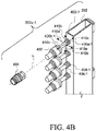
- FIG. 4B illustrates a perspective view of the components of an alternative connector assembly 302a-1 connected to the first liquid manifold 202, according to one embodiment of the present disclosure.
- the connector assembly 302a-1 is similar to the connector assembly 302 ( FIGS. 3 and 4A ) except that the pipe 400-1 includes the flexible portion 408-1 at the proximal end 400a-1 connected to the first liquid manifold 202.
- the straight portion 406-1 is at the distal end 400b-1 of the pipe 400-1 connected to the first connector 402.
- FIG. 4C illustrates a perspective view of the components of another alternative connector assembly 302a-2 connected to the first liquid manifold 202, according to one embodiment of the present disclosure.
- the connector assembly 302a-2 is similar to the connector assembly 302 ( FIGS. 3 and 4A ) except that the pipe 400-2 includes a first straight portion 406a-2 and a second straight portion 406b-2.
- the first straight portion 406a-2 connects the pipe 400-2 to the first liquid manifold 202.
- the second straight portion 406b-2 connects the pipe 400-2 to the first connector 402 at the distal end 400b-2 of the pipe 400-2.
- the flexible portion 408-2 is between the first straight portion 406a-2 and the second straight portion 406b-2.
- the flexible portion 408-2 can be permanently fixed to the first straight portion 406a-2, the second straight portion 406b-2, or both. In one or more embodiments, the flexible portion 408-2 can be configured to detach from the first straight portion 406a-2, the second straight portion 406b-2, or both.
- first straight portion 406a-2, the second straight portion 406b-2, or both can be permanently fixed to the liquid manifold 202 and the first connector 402, respectively; such as by being welded or formed as integral pieces. In one or more embodiments, the first straight portion 406a-2, the second straight portion 406b-2, or both can be configured to be detached from the first liquid manifold 202 and the first connector 402, respectively.
- FIG. 4D illustrates a detailed perspective view of the connector assembly 302a-2 of FIG. 4C , according to one embodiment of the present disclosure.
- the first straight portion 406a-2 can include a threaded portion 412a that interfaces with a threaded portion 408a-2 of the flexible portion 408-2.
- the second straight portion 406b-2 can include a threaded portion 412b that interfaces with a threaded potion 408b-2 of the flexible portion 408-2.
- the threaded portions 412a, 412b, 408a-2, and 408b-2 allow the flexible portion 408-2 to detach from the first straight portion 406a-2 and the second straight portion 406b-2.
- the first straight portion 406a-2 can also include a seal 414a for making a liquid-tight connection between the first straight portion 406a-2 and the flexible portion 408-2.
- the second straight portion 406b-2 can also include a seal 414b for making a liquid-tight connection between the second straight portion 406b-2 and the flexible portion 408-2.
- the flexible portion 408-2 can include one or both of the seals 414a and 414b, or additional seals.
- the second straight portion 406b-2 can instead be considered part of the first connector 402.
- the second straight portion 406b-2 is integral with or formed as part of the first connector 402
- the second straight portion 406b-2 can instead be considered an element of the first connector 402.
- the connector assembly 302a-2 instead includes the first straight portion 406a-2 and the flexible portion 408-2, similar to the connector assembly 302a of FIG. 4A .
- FIG. 5A illustrates a perspective view of inserting the sled 300 into the liquid cooling manifold system 200, according to one embodiment of the present disclosure.
- FIG. 5B illustrates a perspective view of the sled 300 of FIG. 5A connected to the liquid cooling manifold system 200, according to one embodiment of the present disclosure.
- the second connectors 404 of the sled 300 are directed towards the first connectors 402 attached to the first liquid manifold 202 and the second liquid manifold 204. Because each connector assembly 302 includes the flexible portion 408, the pipe 400 can flex to assist in the alignment of the first connector 402 to the second connector 404.
- the flexible portions 408 of the connector assemblies 302 can remain flexed, if needed.
- the connector assemblies 302 therefore allow the sled 300, or any component 104, to be quickly attached and detached from the liquid cooling manifold system 200 without leaking liquid coolant and without needing to precisely align the first connectors 402 and the second connectors 404 prior engagement, simply by inserting the component 104 into a slot 108.
- the connector assemblies 302 provide a floating connection between the liquid cooling manifold system 200 and the components 104 that can tolerate movement of the components 104 relative to the liquid cooling manifold system 200, such as in the event of, for example, an earthquake on unintentional movement of the components 104.
Landscapes
- Engineering & Computer Science (AREA)
- Microelectronics & Electronic Packaging (AREA)
- General Engineering & Computer Science (AREA)
- Physics & Mathematics (AREA)
- Thermal Sciences (AREA)
- Computer Hardware Design (AREA)
- Mechanical Engineering (AREA)
- Cooling Or The Like Of Electrical Apparatus (AREA)
- Branch Pipes, Bends, And The Like (AREA)
Applications Claiming Priority (2)
| Application Number | Priority Date | Filing Date | Title |
|---|---|---|---|
| US201862779845P | 2018-12-14 | 2018-12-14 | |
| US16/295,883 US10921070B2 (en) | 2018-12-14 | 2019-03-07 | Connector assembly for liquid cooling |
Publications (2)
| Publication Number | Publication Date |
|---|---|
| EP3668293A1 true EP3668293A1 (de) | 2020-06-17 |
| EP3668293B1 EP3668293B1 (de) | 2024-04-03 |
Family
ID=67226103
Family Applications (1)
| Application Number | Title | Priority Date | Filing Date |
|---|---|---|---|
| EP19185413.2A Active EP3668293B1 (de) | 2018-12-14 | 2019-07-10 | Verbinderanordnung und serverschrank |
Country Status (5)
| Country | Link |
|---|---|
| US (1) | US10921070B2 (de) |
| EP (1) | EP3668293B1 (de) |
| JP (1) | JP6889217B2 (de) |
| CN (1) | CN111328237B (de) |
| TW (1) | TWI710310B (de) |
Families Citing this family (22)
| Publication number | Priority date | Publication date | Assignee | Title |
|---|---|---|---|---|
| CN114071945A (zh) | 2020-08-06 | 2022-02-18 | 台达电子工业股份有限公司 | 液冷导管 |
| TWI757821B (zh) * | 2020-08-06 | 2022-03-11 | 台達電子工業股份有限公司 | 液冷導管 |
| WO2022047360A1 (en) * | 2020-08-31 | 2022-03-03 | Hoffman Enclosures Inc. | Mounting interface for liquid manifold and electronics rack |
| US11445641B1 (en) * | 2021-02-23 | 2022-09-13 | Baidu Usa Llc | Advanced fluid connection design for multiple phase system |
| US11877428B2 (en) * | 2021-04-20 | 2024-01-16 | Dell Products L.P. | Modular horizontal rack manifold for liquid cooling |
| US11683910B2 (en) * | 2021-04-27 | 2023-06-20 | Quanta Computer Inc. | Hot plug redundant pump for cooling system |
| US11895809B2 (en) * | 2021-05-12 | 2024-02-06 | Nvidia Corporation | Intelligent leak sensor system for datacenter cooling systems |
| CN112954989B (zh) * | 2021-05-18 | 2021-09-10 | 四川斯艾普电子科技有限公司 | 一种雷达液冷装置 |
| CN115904014A (zh) | 2021-08-05 | 2023-04-04 | 富联精密电子(天津)有限公司 | 液冷结构及服务器 |
| TWI814049B (zh) * | 2021-08-05 | 2023-09-01 | 新加坡商鴻運科股份有限公司 | 液冷結構及伺服器 |
| US12031780B2 (en) | 2021-08-11 | 2024-07-09 | Hoffman Enclosures Inc. | Liquid manifold for electronics cabinet |
| US11892252B2 (en) * | 2021-08-12 | 2024-02-06 | Asia Vital Components Co., Ltd. | Adaptable liquid connector structure |
| US11980007B2 (en) * | 2021-12-21 | 2024-05-07 | Baidu Usa Llc | Cooling distribution unit for electronic racks |
| US11997831B2 (en) * | 2021-12-21 | 2024-05-28 | Baidu Usa Llc | Connector alignment design for servers |
| US11913576B2 (en) * | 2022-02-16 | 2024-02-27 | ZT Group Int'l, Inc. | Devices and methods for constraining liquid cooling tubes in liquid cooling servers |
| TWI807803B (zh) * | 2022-04-27 | 2023-07-01 | 新加坡商鴻運科股份有限公司 | 服務器機架以及服務器組件 |
| CN117998804A (zh) * | 2022-10-27 | 2024-05-07 | 富联精密电子(天津)有限公司 | 歧管、机柜及数据中心冷却系统 |
| US12235056B1 (en) * | 2022-12-27 | 2025-02-25 | ZT Group Int'l, Inc. | System for blind mate hydraulic connections |
| US20250169033A1 (en) * | 2023-11-21 | 2025-05-22 | Zt Group Int'l, Inc. Dba Zt Systems | Fluid reservoir device for computing system |
| US12477686B2 (en) * | 2024-01-31 | 2025-11-18 | Dell Products L.P. | Liquid cooling bench clip |
| US20250338454A1 (en) * | 2024-04-24 | 2025-10-30 | ZT Group Int'l, Inc. | Configurable liquid manifold for server rack |
| KR102915115B1 (ko) * | 2024-11-20 | 2026-01-19 | 정태영 | 냉각 시스템이 구비된 랙 유닛 |
Citations (8)
| Publication number | Priority date | Publication date | Assignee | Title |
|---|---|---|---|---|
| US20040008483A1 (en) * | 2002-07-13 | 2004-01-15 | Kioan Cheon | Water cooling type cooling system for electronic device |
| US20050241799A1 (en) * | 2004-04-29 | 2005-11-03 | Hewlett-Packard Development Company, L.P. | High serviceability liquid cooling loop using flexible bellows |
| US20140240920A1 (en) * | 2013-02-22 | 2014-08-28 | International Business Machines Corporation | System for mounting and cooling a computer component |
| US20150237767A1 (en) * | 2011-06-27 | 2015-08-20 | Ebullient, Llc | Heat sink for use with pumped coolant |
| US20160242318A1 (en) * | 2015-02-12 | 2016-08-18 | International Business Machines Corporation | Flexible coolant manifold - heat sink assembly |
| US20160242326A1 (en) * | 2015-02-12 | 2016-08-18 | International Business Machines Corporation | Cooling system with integrated fill and drain pump |
| US20170332520A1 (en) * | 2011-11-28 | 2017-11-16 | Asetek Danmark A/S | Cooling system for a server |
| WO2018045761A1 (zh) * | 2016-09-09 | 2018-03-15 | 华为技术有限公司 | 液冷模块及液冷设备 |
Family Cites Families (28)
| Publication number | Priority date | Publication date | Assignee | Title |
|---|---|---|---|---|
| US4289295A (en) * | 1978-11-06 | 1981-09-15 | Allread Alan R | Self-sealing connector |
| US5324114A (en) | 1992-01-02 | 1994-06-28 | Waekon Industries, Inc. | Temperature and pressure sensor for cooling systems and other pressurized systems |
| US6693797B2 (en) * | 2002-01-04 | 2004-02-17 | Intel Corporation | Computer system having a chassis-level thermal interface component and a frame-level thermal interface component that are thermally engageable with and disengageable from one another |
| US20050241803A1 (en) | 2004-04-29 | 2005-11-03 | Hewlett-Packard Development Company, L.P. | Liquid cooling loop using tubing and bellows for stress isolation and tolerance variation |
| US7342789B2 (en) * | 2005-06-30 | 2008-03-11 | International Business Machines Corporation | Method and apparatus for cooling an equipment enclosure through closed-loop, liquid-assisted air cooling in combination with direct liquid cooling |
| US7420808B2 (en) * | 2006-10-10 | 2008-09-02 | International Business Machines Corporation | Liquid-based cooling system for cooling a multi-component electronics system |
| JP2009273515A (ja) | 2008-05-12 | 2009-11-26 | Corona Giken Kogyo Kk | ろ過器具 |
| US7983040B2 (en) * | 2008-10-23 | 2011-07-19 | International Business Machines Corporation | Apparatus and method for facilitating pumped immersion-cooling of an electronic subsystem |
| US8027162B2 (en) * | 2009-09-24 | 2011-09-27 | International Business Machines Corporation | Liquid-cooled electronics apparatus and methods of fabrication |
| TW201221039A (en) | 2010-11-09 | 2012-05-16 | Hon Hai Prec Ind Co Ltd | Liquid cooling system |
| US8291941B1 (en) | 2011-11-04 | 2012-10-23 | Blue Gentian, Llc | Expandable and contractible hose |
| EP2630982B1 (de) | 2012-02-22 | 2017-04-05 | Erbe Elektromedizin GmbH | Kryochirurgisches Instrument und Stecker mit Entlüftungsöffnung für dieses |
| CN103425211A (zh) | 2012-05-15 | 2013-12-04 | 鸿富锦精密工业(深圳)有限公司 | 服务器及其机架 |
| US20130312846A1 (en) * | 2012-05-25 | 2013-11-28 | André Sloth Eriksen | Fluid connector for a cooling system |
| US8854808B2 (en) * | 2012-06-27 | 2014-10-07 | International Business Machines Corporation | Fitting for flexible manifold system |
| US9351428B2 (en) | 2014-08-29 | 2016-05-24 | Lenovo Enterprise Solutions (Singapore) Pte. Ltd. | Blind docking apparatus to enable liquid cooling in compute nodes |
| CN204231771U (zh) * | 2014-10-28 | 2015-03-25 | 储敏健 | 换热主机及具有其的液体浸没冷却服务器系统 |
| CN105630098B (zh) * | 2014-11-26 | 2019-04-16 | 英业达科技有限公司 | 服务器及其机壳 |
| TWI590571B (zh) * | 2014-12-08 | 2017-07-01 | 強生控制科技公司 | 可變速驅動器系統及冷卻系統 |
| EP3257343A4 (de) | 2015-02-13 | 2018-03-14 | Hewlett-Packard Enterprise Development LP | Kühlmittelverteilungseinheit |
| CN204631750U (zh) * | 2015-03-31 | 2015-09-09 | 广东申菱空调设备有限公司 | 水环自然冷却热管空调和液冷装置结合的服务器散热系统 |
| US10448543B2 (en) | 2015-05-04 | 2019-10-15 | Google Llc | Cooling electronic devices in a data center |
| AU2016276292B2 (en) | 2015-06-10 | 2020-03-12 | Stucchi S.P.A. | Anti-unscrewing quick coupling fitting |
| US9655281B2 (en) * | 2015-06-26 | 2017-05-16 | Seagate Technology Llc | Modular cooling system |
| US10238010B2 (en) * | 2015-12-21 | 2019-03-19 | Dell Products, L.P. | Rackmount appliance for server and rack liquid management and water control policy execution |
| US10299413B2 (en) * | 2017-02-21 | 2019-05-21 | Baidu Usa Llc | Modular self-aligning liquid heat removal coupling system for electronic racks |
| US10609840B2 (en) * | 2017-04-18 | 2020-03-31 | Baidu Usa Llc | Modular quick-release liquid heat removal coupling system for electronic racks |
| CN208016206U (zh) * | 2018-03-14 | 2018-10-26 | 郑州金恒电子技术有限公司 | 一种高效服务器机房冷却系统 |
-
2019
- 2019-03-07 US US16/295,883 patent/US10921070B2/en active Active
- 2019-06-11 TW TW108120161A patent/TWI710310B/zh active
- 2019-06-25 CN CN201910553120.7A patent/CN111328237B/zh active Active
- 2019-07-10 EP EP19185413.2A patent/EP3668293B1/de active Active
- 2019-09-09 JP JP2019164042A patent/JP6889217B2/ja active Active
Patent Citations (9)
| Publication number | Priority date | Publication date | Assignee | Title |
|---|---|---|---|---|
| US20040008483A1 (en) * | 2002-07-13 | 2004-01-15 | Kioan Cheon | Water cooling type cooling system for electronic device |
| US20050241799A1 (en) * | 2004-04-29 | 2005-11-03 | Hewlett-Packard Development Company, L.P. | High serviceability liquid cooling loop using flexible bellows |
| US20150237767A1 (en) * | 2011-06-27 | 2015-08-20 | Ebullient, Llc | Heat sink for use with pumped coolant |
| US20170332520A1 (en) * | 2011-11-28 | 2017-11-16 | Asetek Danmark A/S | Cooling system for a server |
| US20140240920A1 (en) * | 2013-02-22 | 2014-08-28 | International Business Machines Corporation | System for mounting and cooling a computer component |
| US20160242318A1 (en) * | 2015-02-12 | 2016-08-18 | International Business Machines Corporation | Flexible coolant manifold - heat sink assembly |
| US20160242326A1 (en) * | 2015-02-12 | 2016-08-18 | International Business Machines Corporation | Cooling system with integrated fill and drain pump |
| WO2018045761A1 (zh) * | 2016-09-09 | 2018-03-15 | 华为技术有限公司 | 液冷模块及液冷设备 |
| US20190223323A1 (en) * | 2016-09-09 | 2019-07-18 | Huawei Technologies Co., Ltd. | Liquid Cooling Apparatus and Liquid Cooling Device |
Also Published As
| Publication number | Publication date |
|---|---|
| TWI710310B (zh) | 2020-11-11 |
| US20200191504A1 (en) | 2020-06-18 |
| US10921070B2 (en) | 2021-02-16 |
| JP6889217B2 (ja) | 2021-06-18 |
| EP3668293B1 (de) | 2024-04-03 |
| JP2020095684A (ja) | 2020-06-18 |
| CN111328237B (zh) | 2021-06-29 |
| CN111328237A (zh) | 2020-06-23 |
| TW202023350A (zh) | 2020-06-16 |
Similar Documents
| Publication | Publication Date | Title |
|---|---|---|
| EP3668293A1 (de) | Verbinderanordnung und serverschrank | |
| US10897834B2 (en) | Coupling assemblies for connecting fluid-carrying components | |
| US9351428B2 (en) | Blind docking apparatus to enable liquid cooling in compute nodes | |
| US11984572B2 (en) | Battery cooling system | |
| CN113811145B (zh) | 用于液体冷却it服务器的连接器接口 | |
| CN104349638B (zh) | 机柜液冷系统及机柜 | |
| US10385996B2 (en) | Tapering couplers for connecting fluid flow components | |
| CN103687437A (zh) | 冷却单元和电子设备 | |
| US10132433B2 (en) | Releasable, threadless conduit connector for liquid manifold | |
| US9693483B2 (en) | Cooling device for heat-generating devices | |
| JP6110554B2 (ja) | 支持部材 | |
| CN112040730B (zh) | 一种阵面电源液冷插箱 | |
| CN118284004A (zh) | 液冷分配单元、机柜及柜式服务器 | |
| US20240349450A1 (en) | Liquid cooling system with rotatable joint | |
| CN118921965A (zh) | 一种解耦型液冷服务器机柜和液冷服务器系统 | |
| US20250140980A1 (en) | Arrangement and method for thermal management in a battery pack | |
| US20110162818A1 (en) | Providing Connection Elements For Connecting Fluid Pipes To Carry Cooling Fluid In A System | |
| JP2026058955A (ja) | 冷媒循環装置 | |
| CN121455297A (zh) | 用于计算系统的液冷装置和具有液冷装置的计算系统 | |
| CN121739642A (zh) | 制冷剂循环装置 | |
| CN119497335A (zh) | 一种柜门式液冷分配单元及计算设备 | |
| HK1207412A1 (en) | Fluid connector for a cooling system | |
| HK1207412B (en) | Fluid connector for a cooling system |
Legal Events
| Date | Code | Title | Description |
|---|---|---|---|
| PUAI | Public reference made under article 153(3) epc to a published international application that has entered the european phase |
Free format text: ORIGINAL CODE: 0009012 |
|
| STAA | Information on the status of an ep patent application or granted ep patent |
Free format text: STATUS: THE APPLICATION HAS BEEN PUBLISHED |
|
| AK | Designated contracting states |
Kind code of ref document: A1 Designated state(s): AL AT BE BG CH CY CZ DE DK EE ES FI FR GB GR HR HU IE IS IT LI LT LU LV MC MK MT NL NO PL PT RO RS SE SI SK SM TR |
|
| AX | Request for extension of the european patent |
Extension state: BA ME |
|
| STAA | Information on the status of an ep patent application or granted ep patent |
Free format text: STATUS: REQUEST FOR EXAMINATION WAS MADE |
|
| 17P | Request for examination filed |
Effective date: 20200714 |
|
| RBV | Designated contracting states (corrected) |
Designated state(s): AL AT BE BG CH CY CZ DE DK EE ES FI FR GB GR HR HU IE IS IT LI LT LU LV MC MK MT NL NO PL PT RO RS SE SI SK SM TR |
|
| STAA | Information on the status of an ep patent application or granted ep patent |
Free format text: STATUS: EXAMINATION IS IN PROGRESS |
|
| 17Q | First examination report despatched |
Effective date: 20220104 |
|
| GRAP | Despatch of communication of intention to grant a patent |
Free format text: ORIGINAL CODE: EPIDOSNIGR1 |
|
| STAA | Information on the status of an ep patent application or granted ep patent |
Free format text: STATUS: GRANT OF PATENT IS INTENDED |
|
| INTG | Intention to grant announced |
Effective date: 20231109 |
|
| GRAS | Grant fee paid |
Free format text: ORIGINAL CODE: EPIDOSNIGR3 |
|
| GRAA | (expected) grant |
Free format text: ORIGINAL CODE: 0009210 |
|
| STAA | Information on the status of an ep patent application or granted ep patent |
Free format text: STATUS: THE PATENT HAS BEEN GRANTED |
|
| AK | Designated contracting states |
Kind code of ref document: B1 Designated state(s): AL AT BE BG CH CY CZ DE DK EE ES FI FR GB GR HR HU IE IS IT LI LT LU LV MC MK MT NL NO PL PT RO RS SE SI SK SM TR |
|
| REG | Reference to a national code |
Ref country code: GB Ref legal event code: FG4D |
|
| REG | Reference to a national code |
Ref country code: CH Ref legal event code: EP |
|
| REG | Reference to a national code |
Ref country code: IE Ref legal event code: FG4D |
|
| REG | Reference to a national code |
Ref country code: DE Ref legal event code: R096 Ref document number: 602019049322 Country of ref document: DE |
|
| REG | Reference to a national code |
Ref country code: LT Ref legal event code: MG9D |
|
| REG | Reference to a national code |
Ref country code: NL Ref legal event code: MP Effective date: 20240403 |
|
| REG | Reference to a national code |
Ref country code: AT Ref legal event code: MK05 Ref document number: 1673823 Country of ref document: AT Kind code of ref document: T Effective date: 20240403 |
|
| PG25 | Lapsed in a contracting state [announced via postgrant information from national office to epo] |
Ref country code: NL Free format text: LAPSE BECAUSE OF FAILURE TO SUBMIT A TRANSLATION OF THE DESCRIPTION OR TO PAY THE FEE WITHIN THE PRESCRIBED TIME-LIMIT Effective date: 20240403 |
|
| PG25 | Lapsed in a contracting state [announced via postgrant information from national office to epo] |
Ref country code: NL Free format text: LAPSE BECAUSE OF FAILURE TO SUBMIT A TRANSLATION OF THE DESCRIPTION OR TO PAY THE FEE WITHIN THE PRESCRIBED TIME-LIMIT Effective date: 20240403 |
|
| PG25 | Lapsed in a contracting state [announced via postgrant information from national office to epo] |
Ref country code: IS Free format text: LAPSE BECAUSE OF FAILURE TO SUBMIT A TRANSLATION OF THE DESCRIPTION OR TO PAY THE FEE WITHIN THE PRESCRIBED TIME-LIMIT Effective date: 20240803 |
|
| PG25 | Lapsed in a contracting state [announced via postgrant information from national office to epo] |
Ref country code: BG Free format text: LAPSE BECAUSE OF FAILURE TO SUBMIT A TRANSLATION OF THE DESCRIPTION OR TO PAY THE FEE WITHIN THE PRESCRIBED TIME-LIMIT Effective date: 20240403 |
|
| PG25 | Lapsed in a contracting state [announced via postgrant information from national office to epo] |
Ref country code: HR Free format text: LAPSE BECAUSE OF FAILURE TO SUBMIT A TRANSLATION OF THE DESCRIPTION OR TO PAY THE FEE WITHIN THE PRESCRIBED TIME-LIMIT Effective date: 20240403 Ref country code: FI Free format text: LAPSE BECAUSE OF FAILURE TO SUBMIT A TRANSLATION OF THE DESCRIPTION OR TO PAY THE FEE WITHIN THE PRESCRIBED TIME-LIMIT Effective date: 20240403 |
|
| PG25 | Lapsed in a contracting state [announced via postgrant information from national office to epo] |
Ref country code: GR Free format text: LAPSE BECAUSE OF FAILURE TO SUBMIT A TRANSLATION OF THE DESCRIPTION OR TO PAY THE FEE WITHIN THE PRESCRIBED TIME-LIMIT Effective date: 20240704 |
|
| PG25 | Lapsed in a contracting state [announced via postgrant information from national office to epo] |
Ref country code: PT Free format text: LAPSE BECAUSE OF FAILURE TO SUBMIT A TRANSLATION OF THE DESCRIPTION OR TO PAY THE FEE WITHIN THE PRESCRIBED TIME-LIMIT Effective date: 20240805 |
|
| PG25 | Lapsed in a contracting state [announced via postgrant information from national office to epo] |
Ref country code: ES Free format text: LAPSE BECAUSE OF FAILURE TO SUBMIT A TRANSLATION OF THE DESCRIPTION OR TO PAY THE FEE WITHIN THE PRESCRIBED TIME-LIMIT Effective date: 20240403 |
|
| PG25 | Lapsed in a contracting state [announced via postgrant information from national office to epo] |
Ref country code: CZ Free format text: LAPSE BECAUSE OF FAILURE TO SUBMIT A TRANSLATION OF THE DESCRIPTION OR TO PAY THE FEE WITHIN THE PRESCRIBED TIME-LIMIT Effective date: 20240403 |
|
| PG25 | Lapsed in a contracting state [announced via postgrant information from national office to epo] |
Ref country code: AT Free format text: LAPSE BECAUSE OF FAILURE TO SUBMIT A TRANSLATION OF THE DESCRIPTION OR TO PAY THE FEE WITHIN THE PRESCRIBED TIME-LIMIT Effective date: 20240403 |
|
| PG25 | Lapsed in a contracting state [announced via postgrant information from national office to epo] |
Ref country code: PL Free format text: LAPSE BECAUSE OF FAILURE TO SUBMIT A TRANSLATION OF THE DESCRIPTION OR TO PAY THE FEE WITHIN THE PRESCRIBED TIME-LIMIT Effective date: 20240403 |
|
| PG25 | Lapsed in a contracting state [announced via postgrant information from national office to epo] |
Ref country code: LV Free format text: LAPSE BECAUSE OF FAILURE TO SUBMIT A TRANSLATION OF THE DESCRIPTION OR TO PAY THE FEE WITHIN THE PRESCRIBED TIME-LIMIT Effective date: 20240403 |
|
| PG25 | Lapsed in a contracting state [announced via postgrant information from national office to epo] |
Ref country code: PT Free format text: LAPSE BECAUSE OF FAILURE TO SUBMIT A TRANSLATION OF THE DESCRIPTION OR TO PAY THE FEE WITHIN THE PRESCRIBED TIME-LIMIT Effective date: 20240805 Ref country code: PL Free format text: LAPSE BECAUSE OF FAILURE TO SUBMIT A TRANSLATION OF THE DESCRIPTION OR TO PAY THE FEE WITHIN THE PRESCRIBED TIME-LIMIT Effective date: 20240403 Ref country code: NO Free format text: LAPSE BECAUSE OF FAILURE TO SUBMIT A TRANSLATION OF THE DESCRIPTION OR TO PAY THE FEE WITHIN THE PRESCRIBED TIME-LIMIT Effective date: 20240703 Ref country code: LV Free format text: LAPSE BECAUSE OF FAILURE TO SUBMIT A TRANSLATION OF THE DESCRIPTION OR TO PAY THE FEE WITHIN THE PRESCRIBED TIME-LIMIT Effective date: 20240403 Ref country code: IS Free format text: LAPSE BECAUSE OF FAILURE TO SUBMIT A TRANSLATION OF THE DESCRIPTION OR TO PAY THE FEE WITHIN THE PRESCRIBED TIME-LIMIT Effective date: 20240803 Ref country code: HR Free format text: LAPSE BECAUSE OF FAILURE TO SUBMIT A TRANSLATION OF THE DESCRIPTION OR TO PAY THE FEE WITHIN THE PRESCRIBED TIME-LIMIT Effective date: 20240403 Ref country code: GR Free format text: LAPSE BECAUSE OF FAILURE TO SUBMIT A TRANSLATION OF THE DESCRIPTION OR TO PAY THE FEE WITHIN THE PRESCRIBED TIME-LIMIT Effective date: 20240704 Ref country code: FI Free format text: LAPSE BECAUSE OF FAILURE TO SUBMIT A TRANSLATION OF THE DESCRIPTION OR TO PAY THE FEE WITHIN THE PRESCRIBED TIME-LIMIT Effective date: 20240403 Ref country code: ES Free format text: LAPSE BECAUSE OF FAILURE TO SUBMIT A TRANSLATION OF THE DESCRIPTION OR TO PAY THE FEE WITHIN THE PRESCRIBED TIME-LIMIT Effective date: 20240403 Ref country code: CZ Free format text: LAPSE BECAUSE OF FAILURE TO SUBMIT A TRANSLATION OF THE DESCRIPTION OR TO PAY THE FEE WITHIN THE PRESCRIBED TIME-LIMIT Effective date: 20240403 Ref country code: BG Free format text: LAPSE BECAUSE OF FAILURE TO SUBMIT A TRANSLATION OF THE DESCRIPTION OR TO PAY THE FEE WITHIN THE PRESCRIBED TIME-LIMIT Effective date: 20240403 Ref country code: AT Free format text: LAPSE BECAUSE OF FAILURE TO SUBMIT A TRANSLATION OF THE DESCRIPTION OR TO PAY THE FEE WITHIN THE PRESCRIBED TIME-LIMIT Effective date: 20240403 Ref country code: RS Free format text: LAPSE BECAUSE OF FAILURE TO SUBMIT A TRANSLATION OF THE DESCRIPTION OR TO PAY THE FEE WITHIN THE PRESCRIBED TIME-LIMIT Effective date: 20240703 |
|
| REG | Reference to a national code |
Ref country code: DE Ref legal event code: R097 Ref document number: 602019049322 Country of ref document: DE |
|
| PG25 | Lapsed in a contracting state [announced via postgrant information from national office to epo] |
Ref country code: DK Free format text: LAPSE BECAUSE OF FAILURE TO SUBMIT A TRANSLATION OF THE DESCRIPTION OR TO PAY THE FEE WITHIN THE PRESCRIBED TIME-LIMIT Effective date: 20240403 |
|
| PG25 | Lapsed in a contracting state [announced via postgrant information from national office to epo] |
Ref country code: EE Free format text: LAPSE BECAUSE OF FAILURE TO SUBMIT A TRANSLATION OF THE DESCRIPTION OR TO PAY THE FEE WITHIN THE PRESCRIBED TIME-LIMIT Effective date: 20240403 |
|
| PG25 | Lapsed in a contracting state [announced via postgrant information from national office to epo] |
Ref country code: RO Free format text: LAPSE BECAUSE OF FAILURE TO SUBMIT A TRANSLATION OF THE DESCRIPTION OR TO PAY THE FEE WITHIN THE PRESCRIBED TIME-LIMIT Effective date: 20240403 Ref country code: SK Free format text: LAPSE BECAUSE OF FAILURE TO SUBMIT A TRANSLATION OF THE DESCRIPTION OR TO PAY THE FEE WITHIN THE PRESCRIBED TIME-LIMIT Effective date: 20240403 |
|
| PG25 | Lapsed in a contracting state [announced via postgrant information from national office to epo] |
Ref country code: SM Free format text: LAPSE BECAUSE OF FAILURE TO SUBMIT A TRANSLATION OF THE DESCRIPTION OR TO PAY THE FEE WITHIN THE PRESCRIBED TIME-LIMIT Effective date: 20240403 |
|
| PG25 | Lapsed in a contracting state [announced via postgrant information from national office to epo] |
Ref country code: SM Free format text: LAPSE BECAUSE OF FAILURE TO SUBMIT A TRANSLATION OF THE DESCRIPTION OR TO PAY THE FEE WITHIN THE PRESCRIBED TIME-LIMIT Effective date: 20240403 Ref country code: SK Free format text: LAPSE BECAUSE OF FAILURE TO SUBMIT A TRANSLATION OF THE DESCRIPTION OR TO PAY THE FEE WITHIN THE PRESCRIBED TIME-LIMIT Effective date: 20240403 Ref country code: RO Free format text: LAPSE BECAUSE OF FAILURE TO SUBMIT A TRANSLATION OF THE DESCRIPTION OR TO PAY THE FEE WITHIN THE PRESCRIBED TIME-LIMIT Effective date: 20240403 Ref country code: EE Free format text: LAPSE BECAUSE OF FAILURE TO SUBMIT A TRANSLATION OF THE DESCRIPTION OR TO PAY THE FEE WITHIN THE PRESCRIBED TIME-LIMIT Effective date: 20240403 Ref country code: DK Free format text: LAPSE BECAUSE OF FAILURE TO SUBMIT A TRANSLATION OF THE DESCRIPTION OR TO PAY THE FEE WITHIN THE PRESCRIBED TIME-LIMIT Effective date: 20240403 |
|
| PG25 | Lapsed in a contracting state [announced via postgrant information from national office to epo] |
Ref country code: MC Free format text: LAPSE BECAUSE OF FAILURE TO SUBMIT A TRANSLATION OF THE DESCRIPTION OR TO PAY THE FEE WITHIN THE PRESCRIBED TIME-LIMIT Effective date: 20240403 |
|
| PLBE | No opposition filed within time limit |
Free format text: ORIGINAL CODE: 0009261 |
|
| STAA | Information on the status of an ep patent application or granted ep patent |
Free format text: STATUS: NO OPPOSITION FILED WITHIN TIME LIMIT |
|
| REG | Reference to a national code |
Ref country code: CH Ref legal event code: PL |
|
| 26N | No opposition filed |
Effective date: 20250106 |
|
| PG25 | Lapsed in a contracting state [announced via postgrant information from national office to epo] |
Ref country code: LU Free format text: LAPSE BECAUSE OF NON-PAYMENT OF DUE FEES Effective date: 20240710 |
|
| PG25 | Lapsed in a contracting state [announced via postgrant information from national office to epo] |
Ref country code: LU Free format text: LAPSE BECAUSE OF NON-PAYMENT OF DUE FEES Effective date: 20240710 |
|
| PG25 | Lapsed in a contracting state [announced via postgrant information from national office to epo] |
Ref country code: SI Free format text: LAPSE BECAUSE OF FAILURE TO SUBMIT A TRANSLATION OF THE DESCRIPTION OR TO PAY THE FEE WITHIN THE PRESCRIBED TIME-LIMIT Effective date: 20240403 Ref country code: BE Free format text: LAPSE BECAUSE OF NON-PAYMENT OF DUE FEES Effective date: 20240731 Ref country code: CH Free format text: LAPSE BECAUSE OF NON-PAYMENT OF DUE FEES Effective date: 20240731 |
|
| REG | Reference to a national code |
Ref country code: BE Ref legal event code: MM Effective date: 20240731 |
|
| PGFP | Annual fee paid to national office [announced via postgrant information from national office to epo] |
Ref country code: GB Payment date: 20250522 Year of fee payment: 7 |
|
| PGFP | Annual fee paid to national office [announced via postgrant information from national office to epo] |
Ref country code: FR Payment date: 20250523 Year of fee payment: 7 |
|
| PG25 | Lapsed in a contracting state [announced via postgrant information from national office to epo] |
Ref country code: IE Free format text: LAPSE BECAUSE OF NON-PAYMENT OF DUE FEES Effective date: 20240710 |
|
| PG25 | Lapsed in a contracting state [announced via postgrant information from national office to epo] |
Ref country code: SE Free format text: LAPSE BECAUSE OF FAILURE TO SUBMIT A TRANSLATION OF THE DESCRIPTION OR TO PAY THE FEE WITHIN THE PRESCRIBED TIME-LIMIT Effective date: 20240403 |
|
| PGFP | Annual fee paid to national office [announced via postgrant information from national office to epo] |
Ref country code: DE Payment date: 20250521 Year of fee payment: 7 |
|
| PG25 | Lapsed in a contracting state [announced via postgrant information from national office to epo] |
Ref country code: CY Free format text: LAPSE BECAUSE OF FAILURE TO SUBMIT A TRANSLATION OF THE DESCRIPTION OR TO PAY THE FEE WITHIN THE PRESCRIBED TIME-LIMIT; INVALID AB INITIO Effective date: 20190710 |
|
| PG25 | Lapsed in a contracting state [announced via postgrant information from national office to epo] |
Ref country code: IT Free format text: LAPSE BECAUSE OF FAILURE TO SUBMIT A TRANSLATION OF THE DESCRIPTION OR TO PAY THE FEE WITHIN THE PRESCRIBED TIME-LIMIT Effective date: 20240403 |
|
| PG25 | Lapsed in a contracting state [announced via postgrant information from national office to epo] |
Ref country code: HU Free format text: LAPSE BECAUSE OF FAILURE TO SUBMIT A TRANSLATION OF THE DESCRIPTION OR TO PAY THE FEE WITHIN THE PRESCRIBED TIME-LIMIT; INVALID AB INITIO Effective date: 20190710 |