EP3668291A1 - Unterdruckflüssigkeitskühlsystem und steuerverfahren dafür - Google Patents
Unterdruckflüssigkeitskühlsystem und steuerverfahren dafür Download PDFInfo
- Publication number
- EP3668291A1 EP3668291A1 EP18852998.6A EP18852998A EP3668291A1 EP 3668291 A1 EP3668291 A1 EP 3668291A1 EP 18852998 A EP18852998 A EP 18852998A EP 3668291 A1 EP3668291 A1 EP 3668291A1
- Authority
- EP
- European Patent Office
- Prior art keywords
- pressure value
- preset pressure
- preset
- vacuum pump
- value
- Prior art date
- Legal status (The legal status is an assumption and is not a legal conclusion. Google has not performed a legal analysis and makes no representation as to the accuracy of the status listed.)
- Granted
Links
Images


Classifications
-
- H—ELECTRICITY
- H05—ELECTRIC TECHNIQUES NOT OTHERWISE PROVIDED FOR
- H05K—PRINTED CIRCUITS; CASINGS OR CONSTRUCTIONAL DETAILS OF ELECTRIC APPARATUS; MANUFACTURE OF ASSEMBLAGES OF ELECTRICAL COMPONENTS
- H05K7/00—Constructional details common to different types of electric apparatus
- H05K7/20—Modifications to facilitate cooling, ventilating, or heating
- H05K7/20218—Modifications to facilitate cooling, ventilating, or heating using a liquid coolant without phase change in electronic enclosures
- H05K7/20272—Accessories for moving fluid, for expanding fluid, for connecting fluid conduits, for distributing fluid, for removing gas or for preventing leakage, e.g. pumps, tanks or manifolds
-
- G—PHYSICS
- G05—CONTROLLING; REGULATING
- G05D—SYSTEMS FOR CONTROLLING OR REGULATING NON-ELECTRIC VARIABLES
- G05D16/00—Control of fluid pressure
- G05D16/20—Control of fluid pressure characterised by the use of electric means
-
- H—ELECTRICITY
- H05—ELECTRIC TECHNIQUES NOT OTHERWISE PROVIDED FOR
- H05K—PRINTED CIRCUITS; CASINGS OR CONSTRUCTIONAL DETAILS OF ELECTRIC APPARATUS; MANUFACTURE OF ASSEMBLAGES OF ELECTRICAL COMPONENTS
- H05K7/00—Constructional details common to different types of electric apparatus
- H05K7/20—Modifications to facilitate cooling, ventilating, or heating
- H05K7/20218—Modifications to facilitate cooling, ventilating, or heating using a liquid coolant without phase change in electronic enclosures
- H05K7/20254—Cold plates transferring heat from heat source to coolant
-
- H—ELECTRICITY
- H05—ELECTRIC TECHNIQUES NOT OTHERWISE PROVIDED FOR
- H05K—PRINTED CIRCUITS; CASINGS OR CONSTRUCTIONAL DETAILS OF ELECTRIC APPARATUS; MANUFACTURE OF ASSEMBLAGES OF ELECTRICAL COMPONENTS
- H05K7/00—Constructional details common to different types of electric apparatus
- H05K7/20—Modifications to facilitate cooling, ventilating, or heating
- H05K7/20218—Modifications to facilitate cooling, ventilating, or heating using a liquid coolant without phase change in electronic enclosures
- H05K7/20281—Thermal management, e.g. liquid flow control
-
- H—ELECTRICITY
- H05—ELECTRIC TECHNIQUES NOT OTHERWISE PROVIDED FOR
- H05K—PRINTED CIRCUITS; CASINGS OR CONSTRUCTIONAL DETAILS OF ELECTRIC APPARATUS; MANUFACTURE OF ASSEMBLAGES OF ELECTRICAL COMPONENTS
- H05K7/00—Constructional details common to different types of electric apparatus
- H05K7/20—Modifications to facilitate cooling, ventilating, or heating
- H05K7/20536—Modifications to facilitate cooling, ventilating, or heating for racks or cabinets of standardised dimensions, e.g. electronic racks for aircraft or telecommunication equipment
- H05K7/20627—Liquid coolant without phase change
-
- H—ELECTRICITY
- H05—ELECTRIC TECHNIQUES NOT OTHERWISE PROVIDED FOR
- H05K—PRINTED CIRCUITS; CASINGS OR CONSTRUCTIONAL DETAILS OF ELECTRIC APPARATUS; MANUFACTURE OF ASSEMBLAGES OF ELECTRICAL COMPONENTS
- H05K7/00—Constructional details common to different types of electric apparatus
- H05K7/20—Modifications to facilitate cooling, ventilating, or heating
- H05K7/20709—Modifications to facilitate cooling, ventilating, or heating for server racks or cabinets; for data centers, e.g. 19-inch computer racks
- H05K7/20763—Liquid cooling without phase change
Definitions
- the present invention belongs to the field of board cooling technologies, and in particular, relates to a negative pressure liquid cooling system and a method for controlling a negative pressure liquid cooling system.
- the power consumption density is power consumption per unit area.
- a large power consumption density means that more heat is accumulated in a same area, and heat dissipation pressure is increased.
- a conventional air-cooled heat dissipation manner cannot meet an increasing heat dissipation requirement of the chip.
- Liquid cooling technologies with high heat dissipation efficiency are widely used in, for example, a plurality of fields such as a data center, a server, and a personal PC.
- a liquid cooling system usually includes a cold plate, a heat exchanger, a pipeline, a liquid pump, and various sensors.
- the cold plate is laminated to a to-be-cooled board, and a fluid channel is disposed inside the cold plate, so that heat of the board can be transferred to a fluid.
- the fluid in the cold plate is flowed to the heat exchanger through the pipeline and the liquid pump, and the heat exchanger may transfer heat of a thermal fluid to a cold fluid, thereby implementing heat dissipation of the board.
- the liquid pump is configured to regulate a flowing speed of a coolant in the pipeline, to regulate a heat exchange speed of the coolant.
- the sensor is configured to detect a pressure, a temperature, and the like in the liquid cooling system.
- a conventional liquid cooling system is usually a positive pressure system, to be specific, a liquid pressure in a pipeline is greater than an ambient pressure outside the pipeline.
- a liquid pressure in a pipeline is greater than an ambient pressure outside the pipeline.
- the present invention provides a negative pressure liquid cooling system and a method for controlling a negative pressure liquid cooling system, to resolve a technical problem of coolant leakage in a conventional liquid cooling system.
- the technical solutions of the present invention are as follows:
- this application provides a method for controlling a negative pressure liquid cooling system, where the method is applied to a negative pressure liquid cooling system, and the negative pressure liquid cooling system includes a cold plate, a coolant storage tank, a vacuum pump, a solenoid valve, a liquid pump, and a heat exchanger, where the cold plate is configured to cool a to-be-cooled device, the coolant storage tank is connected to an outlet of the cold plate, the vacuum pump is connected to the coolant storage tank through the solenoid valve, an inlet of the liquid pump is connected to the coolant storage tank, the heat exchanger includes a first loop and a second loop that are mutually isolated, a fluid in the first loop is used to cool a fluid in the second loop, an inlet of the second loop is connected to an outlet of the liquid pump, and an outlet of the second loop is connected to an inlet of the cold plate; and the method includes: detecting a first pressure value in the coolant storage tank; and enabling the vacuum pump and the solenoid valve when the first
- pressures at the inlet and the outlet of the cold plate are separately controlled, so that the pressures at the inlet and the outlet of the cold plate remain negative.
- a pressure at the outlet of the cold plate can be separately controlled to remain negative, so that a coolant is suppressed in the pipeline, and a coolant leakage phenomenon is avoided. Therefore, damage or a security threat to a to-be-cooled electronic device that is caused by leakage of a conductive operating medium such as water is avoided.
- the method further includes: collecting statistics on a working time ratio of the vacuum pump when the second pressure value is within the second preset pressure range, where the working time ratio is a ratio of an enabling time to a disabling time of the vacuum pump; and disabling the liquid pump and outputting a leakage alarm signal when the working time ratio of the vacuum pump is greater than a first specified value for a preset quantity of consecutive times.
- the statistics on the working time ratio of the vacuum pump is collected.
- a pressure in a water tank may increase, which may cause frequent enabling and disabling of the vacuum pump in a short time. Therefore, a system leakage incident can be predicted based on the working time ratio.
- the method further includes: after the vacuum pump is enabled for first preset duration, if it is detected that the first pressure value in the coolant storage tank is greater than the second preset pressure value, detecting whether the vacuum pump is faulty; and regulating the rotational speed of the liquid pump if it is detected that the vacuum pump is faulty, so that a difference between the second pressure value and the first pressure value is equal to a fifth preset pressure value, where the fifth preset pressure value is greater than 0.
- the method for controlling a negative pressure liquid cooling system provided in this implementation, after the vacuum pump is enabled for the first preset duration, if the pressure in the coolant storage tank still does not reach the first preset pressure range, it is detected whether the vacuum pump is faulty. If the vacuum pump is faulty, the liquid pump is switched to a pressure difference mode, that is, the rotational speed of the liquid pump is regulated, so that a pressure difference between the inlet and the outlet of the cold plate remains a specified value. In addition, a leakage risk is prompted. In the control method, the leakage risk likely caused by the fault of the vacuum pump can be automatically detected, thereby further reducing a leakage risk of the system.
- the negative pressure liquid cooling system further includes a standby vacuum pump connected to the solenoid valve, and after the enabling the vacuum pump and the solenoid valve when the first pressure value is greater than a second preset pressure value, the method further includes: after the vacuum pump is enabled for first preset duration, if it is detected that the first pressure value in the coolant storage tank is greater than the second preset pressure value, detecting whether the vacuum pump is faulty; and enabling the standby vacuum pump if it is detected that the vacuum pump is faulty.
- the standby vacuum pump is disposed in the negative pressure liquid cooling system. After it is detected that the currently-run vacuum pump is faulty, the standby vacuum pump is enabled, so that the negative pressure liquid cooling system remains in a negative pressure state, and a leakage risk of the system is reduced.
- the regulating a rotational speed of the liquid pump, so that the second pressure value is within the second preset pressure range includes: when the second pressure value is greater than the fourth preset pressure value, decreasing the rotational speed of the liquid pump to decrease the second pressure value; or when the second pressure value is less than the third preset pressure value, increasing the rotational speed of the liquid pump to increase the second pressure value.
- a pressure at the inlet of the cold plate is regulated by regulating the rotational speed of the liquid pump, so that the pressure at the inlet of the cold plate is regulated separately to enable the pressure at the inlet of the cold plate to remain negative, a coolant is suppressed in the pipeline, and a coolant leakage risk is reduced.
- this application provides a negative pressure liquid cooling system, including a cold plate, a coolant storage tank, a vacuum pump, a solenoid valve, a liquid pump, a heat exchanger, and a controller, where the cold plate is laminated to a to-be-cooled electronic device, and is configured to cool the to-be-cooled electronic device; an inlet of the coolant storage tank is connected to an outlet of the cold plate, and an outlet of the coolant storage tank is connected to an inlet of the liquid pump; the heat exchanger includes a first loop and a second loop that are mutually isolated, a fluid in the first loop is used to cool a fluid in the second loop, an inlet of the second loop is connected to an outlet of the liquid pump, and an outlet of the second loop is connected to an inlet of the cold plate; and the controller is configured to: control, by controlling working statuses of the vacuum pump and the solenoid valve, a first pressure value in the coolant storage tank to remain within a first preset pressure range; and control,
- pressures at the inlet and the outlet of the cold plate are separately controlled to remain negative.
- a pressure at the outlet of the cold plate can be separately controlled to remain negative, so that a coolant is suppressed in the pipeline, and a coolant leakage phenomenon is avoided. Therefore, damage or a security threat to a to-be-cooled electronic device that is caused by leakage of a conductive operating medium such as water is avoided.
- the system further includes a one-way valve.
- An inlet of the one-way valve is connected to the outlet of the second loop, and an outlet of the one-way valve is connected to the inlet of the cold plate.
- the one-way valve is a passive control component of the negative pressure liquid cooling system.
- a perforation at the inlet of the cold plate is relatively large, a pressure at the perforation increases, and a pressure at the outlet of the one-way valve is greater than a pressure at the inlet of the one-way valve.
- the one-way valve is disabled, and a water flow is rapidly blocked. Therefore, it is ensured that the liquid pump has enough time to regulate a speed, so that the inlet of the cold plate is in a negative pressure state in real time, thereby avoiding a water leakage phenomenon that is caused by a slow response for speed regulation of the liquid pump.
- the system further includes a gas-liquid filter.
- An inlet of the gas-liquid filter is connected to the solenoid valve, an outlet of the gas-liquid filter is connected to the vacuum pump, and the gas-liquid filter is configured to filter water vapor included in gas that is pumped out of the coolant storage tank. Therefore, damage of the water vapor to the vacuum pump is effectively prevented.
- the controller when controlling, by controlling the working statuses of the vacuum pump and the solenoid valve, the first pressure value in the coolant storage tank to remain within the first preset pressure range, is specifically configured to: detect the first pressure value; enable the vacuum pump and the solenoid valve when the first pressure value is greater than a second preset pressure value until the first pressure value is decreased to the first preset pressure range, where a minimum value of the first preset pressure range is a first preset pressure value, the maximum value of the first preset pressure range is the second preset pressure value, and both the first preset pressure value and the second preset pressure value are less than one standard atmosphere; disable the vacuum pump and enable the solenoid valve when the first pressure value is less than the first preset pressure value until the first pressure value is within the first preset pressure range; or when the first pressure value is within the first preset pressure range and the second pressure value is not within the second preset pressure range, control, by controlling the rotational speed of the liquid pump, the second pressure value to remain within the second
- a pressure in the coolant storage tank that is, a pressure at the outlet of the cold plate is detected.
- the vacuum pump and the solenoid valve are enabled, and air is pumped out of the coolant storage tank, so that the pressure in the coolant storage tank is decreased.
- the vacuum pump is disabled and the solenoid valve is enabled, so that air enters the coolant storage tank through the solenoid valve, thereby increasing the pressure in the coolant storage tank.
- the pressure at the outlet of the cold plate remains within a negative pressure range, so that a coolant is suppressed in the pipeline, and a coolant leakage risk is reduced.
- the controller when controlling, by controlling the working statuses of the vacuum pump and the solenoid valve, the pressure in the coolant storage tank to remain within the first preset pressure range, the controller is further configured to: collect statistics on a working time ratio of the vacuum pump when the second pressure value is within the second preset pressure range, where the working time ratio is a ratio of an enabling time to a disabling time of the vacuum pump; and disable the liquid pump when the working time ratio of the vacuum pump is greater than a first specified value for a preset quantity of consecutive times.
- the negative pressure liquid cooling system provided in this implementation, after the vacuum pump is enabled, the statistics on the working time ratio of the vacuum pump is collected.
- a pressure in a water tank may increase, which may cause frequent enabling and disabling of the vacuum pump in a short time. Therefore, a system leakage incident can be predicted based on the working time ratio.
- the controller when controlling, by controlling the working statuses of the vacuum pump and the solenoid valve, the pressure in the coolant storage tank to remain within the first preset pressure range, the controller is further configured to: after the vacuum pump is enabled for first preset duration, if it is detected that the first pressure value in the coolant storage tank is greater than the second preset pressure value, detect whether the vacuum pump is faulty; and regulate the rotational speed of the liquid pump if it is detected that the vacuum pump is faulty, so that a difference between the second pressure value and the first pressure value is equal to a fifth preset pressure value, where the fifth preset pressure value is greater than 0.
- the negative pressure liquid cooling system provided in this implementation, after the vacuum pump is enabled for the first preset duration, if a pressure in the coolant storage tank still does not reach the first preset pressure range, it is detected whether the vacuum pump is faulty. If the vacuum pump is faulty, the liquid pump is switched to a pressure difference mode, that is, the rotational speed of the liquid pump is regulated, so that a pressure difference between the inlet and the outlet of the cold plate remains a specified value. In addition, a leakage risk is prompted. In the control method, the leakage risk likely caused by the fault of the vacuum pump can be automatically detected, thereby further reducing a leakage risk of the system.
- the system further includes a standby vacuum pump connected to the solenoid valve, and when controlling, by controlling the working statuses of the vacuum pump and the solenoid valve, the pressure in the coolant storage tank to remain within the first preset pressure range, the controller is further configured to: after the vacuum pump is enabled for first preset duration, if it is detected that the first pressure value in the coolant storage tank is greater than the second preset pressure value, detect whether the vacuum pump is faulty; and enable the standby vacuum pump if it is detected that the vacuum pump is faulty.
- the standby vacuum pump is added. After it is detected that the currently-run vacuum pump is faulty, the standby vacuum pump is enabled, so that the negative pressure liquid cooling system remains in a negative pressure state, and a leakage risk of the system is reduced.
- the minimum value of the second preset pressure range is a third preset pressure value
- a maximum value of the second preset pressure range is a fourth preset pressure value
- both the third preset pressure value and the fourth preset pressure value are less than one standard atmosphere
- the controller when controlling, by controlling the rotational speed of the liquid pump, the second pressure value to remain within the second preset pressure range, the controller is specifically configured to: decrease the rotational speed of the liquid pump when the second pressure value is greater than the fourth preset pressure value, so that the second pressure value is less than the fourth preset pressure value; or increase the rotational speed of the liquid pump when the second pressure value is less than the third preset pressure value, so that the second pressure value is greater than the third preset pressure value.
- a pressure at the inlet of the cold plate is regulated by regulating the rotational speed of the liquid pump, so that the pressure at the inlet of the cold plate is regulated separately to enable the pressure at the inlet of the cold plate to remain negative, a coolant is suppressed in the pipeline, and a coolant leakage risk is reduced.
- this application further provides a processor, configured to run a program, where when the program runs, the processor performs the method for controlling a negative pressure liquid cooling system in the first aspect.
- a conventional liquid cooling system is usually a positive pressure system, to be specific, a liquid pressure in a pipeline is greater than an ambient pressure outside the pipeline in the system.
- a liquid pressure in a pipeline is greater than an ambient pressure outside the pipeline in the system.
- liquid in the pipeline leaks from the perforation to a to-be-cooled electronic device, causing damage or a security threat to the to-be-cooled electronic device.
- Some conventional liquid cooling systems are negative pressure systems.
- the conventional negative pressure system uses a constant pressure difference between an inlet and an outlet of a cold plate to control a liquid volume in the system. When the system normally works, a pressure in the system can remain negative.
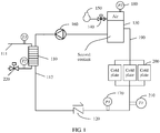
- FIG. 1 is a schematic diagram of a principle of a negative pressure liquid cooling system according to an embodiment of this application.
- a coolant is water
- the coolant may be another type of liquid.
- the system may include a heat exchanger 110, a one-way valve 120, a water tank 130 (namely, a coolant storage tank), a solenoid valve 140, a vacuum pump 150, a liquid pump 160, a first pressure sensor 170, a second pressure sensor 180, a pipeline 190, a cold plate 200, and a controller (not shown in FIG. 1 ).
- the heat exchanger 110 includes a first loop 111 and a second loop 112 that are mutually isolated, where a second coolant in the second loop is used to cool a to-be-cooled electronic device, and a first coolant in the first loop is used to cool the second coolant in the second loop.
- An outlet of the second loop of the heat exchanger 110 is connected to an inlet of the one-way valve 120, an outlet of the one-way valve 120 is connected to an inlet of the cold plate, and an outlet of the cold plate is connected to an inlet of the water tank 130.
- the cold plate 200 is laminated to a board (namely, the to-be-cooled electronic device), and a coolant in the cold plate 200 performs heat exchange with heat emitted by the board, to implement heat dissipation of the board.
- An outlet of the water tank 130 is connected to an inlet of the liquid pump 160, and an outlet of the liquid pump 160 is connected to an inlet of the second loop of the heat exchanger 110.
- the first pressure sensor 170 is disposed at the inlet of the cold plate, and is configured to detect a pressure at the inlet of the cold plate.
- the second pressure sensor 180 is disposed above liquid in the coolant storage tank, and is configured to detect a pressure in the coolant storage tank.
- An overall working process of the negative pressure liquid cooling system is as follows: Heat generated by the board is transferred to a second coolant in the cold plate by using the cold plate 200. After entering the water tank 130 through the pipeline 190, the second coolant is pumped by the liquid pump 160 to the heat exchanger 110. The first coolant in the first loop 111 in the heat exchanger 110 performs heat exchange with the second coolant to cool the second coolant. Then, the second coolant is returned to the cold plate 200 through the one-way valve 120. This process is repeated, and the board is cooled.
- the water tank 130 is filled with a specific quantity of second coolants and a specific amount of air, and the second pressure sensor 180 is disposed above a liquid level of the second coolant, and is configured to detect a pressure in the water tank 130 (namely, a pressure at the outlet of the cold plate), and provide the detected pressure value for the controller.
- the controller controls enabling of the vacuum pump 150 and the solenoid valve 140, the vacuum pump 150 pumps redundant air out of the water tank 130, and when the pressure in the water tank is returned to the first preset pressure range, the controller controls disabling of the vacuum pump 150 and the solenoid valve 140, so that the outlet of the cold plate remains in a negative pressure state.
- the first pressure sensor 170 is disposed at the inlet of the cold plate 200, and is configured to detect the pressure value at the inlet of the cold plate 200 and provide the pressure value for the controller.
- the controller lowers a rotational speed of the liquid pump 160, so that the pressure at the inlet of the cold plate is returned to the second preset pressure range, and after the pressure at the inlet of the cold plate is returned to the second preset pressure range, the rotational speed of the liquid pump 160 is controlled to be stabilized at a current rotational speed.
- values of the second preset pressure range and the first preset pressure range can ensure that a specific positive pressure difference is always remained between the pressure at the inlet of the cold plate and the pressure at the outlet of the cold plate, in other words, the pressure at the inlet of the cold plate is always greater than the pressure at the outlet of the cold plate.
- the pressure at the inlet of the cold plate and the pressure at the outlet of cold plate can be separately controlled to be within a specified negative pressure range, and a pressure difference between the inlet of the cold plate and the outlet of the cold plate remains a specific positive pressure difference.
- the one-way valve 120 is disposed between the outlet of the second loop of the heat exchanger 110 and the inlet of the cold plate.
- the one-way valve 120 is a passive control component of the negative pressure liquid cooling system, and is combined with an active control component of the controller to ensure that the second coolant in the negative pressure liquid cooling system does not leak.
- a perforation at the inlet of the cold plate is relatively large, a pressure at the perforation increases, and a pressure at the outlet of the one-way valve 120 is greater than a pressure at the inlet of the one-way valve 120. In this case, the one-way valve 120 is disabled, and a water flow is rapidly blocked.
- the liquid pump 160 has enough time to regulate a speed, so that the inlet of the cold plate is in a negative pressure state in real time, thereby avoiding a water leakage phenomenon that is caused by a slow response for speed regulation of the liquid pump 160.
- a temperature sensor 210 is disposed at the inlet of the cold plate 200.
- the temperature sensor 210 is configured to detect a temperature of the second coolant at the inlet of the cold plate.
- the controller regulates a liquid volume of the first coolant in the first loop 111 by regulating a regulation valve 220 in the first loop 111, to control a heat exchange capability of the heat exchanger 110, so that the temperature of the second coolant at the inlet of the cold plate reaches the preset range.
- the controller separately controls the inlet and the outlet of the cold plate to ensure that both the inlet and the outlet of the cold plate are in a negative pressure.
- the controller can separately control the rotational speed of the liquid pump and the vacuum pump, to return the inlet and the outlet of the cold plate to a negative pressure, so that the coolant is suppressed in the pipeline, and a coolant leakage phenomenon is avoided.
- the one-way valve is disposed between the outlet of the second loop of the heat exchanger and the inlet of the cold plate, the inlet of the one-way valve is connected to the heat exchanger, and the outlet of the one-way valve is connected to the cold plate.
- a pressure at the perforation increases, a pressure at the outlet of the one-way valve is greater than a pressure at the inlet of the one-way valve, the one-way valve is disabled, and a water flow is rapidly blocked, to save time for the controller to control the liquid pump to regulate a speed, thereby ensuring that the pressure at the inlet of the cold plate is returned to the second preset pressure range.
- FIG. 2 is a schematic diagram of a principle of another negative pressure liquid cooling system according to an embodiment of this application.
- a gas-liquid filter 300 is added to the negative pressure liquid cooling system provided in this embodiment.
- the gas-liquid filter 300 is disposed between a vacuum pump 150 and a solenoid valve 140, and is configured to filter water vapor in gas that is pumped out of a coolant storage tank 130, thereby effectively preventing damage of the water vapor to the vacuum pump 150.
- a connection manner of another component is the same as that in the negative pressure liquid cooling system shown in FIG. 1 , and details are not described herein again.
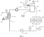
- FIG. 3 is a schematic diagram of a principle of still another negative pressure liquid cooling system according to an embodiment of this application.
- a standby vacuum pump 400 is added in this embodiment based on the embodiment shown in FIG. 1 .
- another vacuum pump may be enabled to ensure that a pressure in the system remains negative.
- a connection manner of another component is the same as that in the negative pressure liquid cooling system shown in FIG. 1 , and details are not described herein again.
- FIG. 4 is a flowchart of a method for controlling a negative pressure liquid cooling system according to an embodiment of this application. The method is applied to the controllers in the negative pressure liquid cooling systems shown in FIG. 1 and FIG. 2 . As shown in FIG. 4 , the method may include the following steps.
- first pressure value is within a first preset pressure range
- S140 is performed. If the first pressure value is greater than a maximum value of the first preset pressure range (namely, a second preset pressure value), S120 is performed. If the first pressure value is less than a minimum value of the first preset pressure range (namely, a first preset pressure value), S130 is performed.
- the pressure in the coolant storage tank is a pressure at an outlet of a cold plate.
- the first pressure value is obtained by a first pressure sensor through collection, and is provided for the controller.
- the minimum value of the first preset pressure range is the first preset pressure value
- the maximum value of the first preset pressure range is the second preset pressure value.
- the first preset pressure value and the second preset pressure value may be set based on an actual system situation. For example, if the pressure in the coolant storage tank is set to 40 kPa, and an allowable error range is ⁇ 1 kPa, the first preset pressure range is [39 kPa, 41 kPa], to be specific, the first preset pressure value is 39 kPa, and the second preset pressure value is 41 kPa.
- the vacuum pump and the solenoid valve are enabled.
- S170 is performed. If the second pressure value is greater than a fourth preset pressure value, S150 is performed. If the second pressure value is less than a third preset pressure value, S160 is performed.
- the pressure at the inlet of the cold plate is regulated, in other words, S140 is performed after S120 or S130.
- a minimum value of the second preset pressure range is the third preset pressure value, and a maximum value of the second preset pressure range is the fourth preset pressure value.
- the second preset pressure range is determined based on an actual system situation. A positive pressure difference between the second preset pressure range and the first preset pressure range is remained, to be specific, the minimum pressure value of the second preset pressure range is greater than the maximum pressure value of the first preset pressure range, in other words, the pressure at the inlet of the cold plate is always greater than the pressure at the outlet of the cold plate.
- the second preset pressure range is [89 kPa, 91 kPa], to be specific, the third preset pressure value is 89 kPa, and the fourth preset pressure value is 91 kPa.
- the working time ratio is a ratio of an enabling time to a disabling time of the vacuum pump.
- a proper working time ratio can avoid a case in which a long working time of the vacuum pump affects a service life of the vacuum pump.
- a pressure in a water tank may increase, which may cause frequent enabling and disabling of the vacuum pump in a short time. Therefore, a system leakage incident can be predicted based on the working time ratio.
- N may be set based on an actual requirement, for example, set to 3.
- the first specified value may be set based on performance of the vacuum pump, for example, set to 3: 1.
- the controller When it is detected that the working time ratio of the vacuum pump is greater than the first specified value for N consecutive times, it indicates that a leakage phenomenon may exist in the negative pressure liquid cooling system, and the controller sends a control signal to control an alarm apparatus to perform alarming. In addition, the controller controls the liquid pump to stop running, and slows a leakage speed of a coolant.
- the alarm apparatus may be an audible and visual alarm, or may send an instant messaging message to a worker, so that the worker quickly checks a leakage status of the system after receiving an alarm signal.
- pressures at the inlet of the cold plate and the outlet of the cold plate are separately detected and controlled.
- the controller can separately control the rotational speed of the liquid pump and the vacuum pump, to return the inlet and the outlet of the cold plate to a negative pressure, so that the coolant is suppressed in the pipeline, and a coolant leakage phenomenon is avoided. Therefore, damage or a security threat to a to-be-cooled electronic device that is caused by leakage of a conductive operating medium such as water is avoided.
- FIG. 5A and FIG. 5B are a flowchart of another method for controlling a negative pressure liquid cooling system according to an embodiment of this application.
- a procedure of detecting whether a vacuum pump is faulty is added, and S120 in FIG. 4 is replaced with the following steps.
- the first preset duration needs to be determined based on working duration that is required to enable a first pressure in a water tank to reach a first preset pressure range when the vacuum pump normally works.
- the first preset duration is determined based on a volume of the water tank and an air pumping rate of the vacuum pump, or is obtained based on test data of the negative pressure liquid cooling system, for example, 60s.
- the liquid pump is switched to a pressure difference mode, to ensure that a pressure difference between an inlet of a cold plate and an outlet of the cold plate is always the fifth preset pressure value, where the fifth preset pressure value is greater than 0, and the fifth preset pressure value may be equal to a difference between a third preset pressure value and the second preset pressure value, or another value.
- a pressure at the inlet of the cold plate may be regulated by regulating the rotational speed of the liquid pump, to ensure that the pressure difference between the inlet and the outlet of the cold plate is a specified positive pressure value.
- the system may be evolved into a positive pressure system.
- the leakage alarm signal is output to prompt that there may be a leakage risk.
- the method for controlling a negative pressure liquid cooling system provided in this embodiment, after the vacuum pump is enabled for the first preset duration, if a pressure in the coolant storage tank still does not reach the first preset pressure range, it is detected whether the vacuum pump is faulty. If the vacuum pump is faulty, the liquid pump is switched to the pressure difference mode, that is, the rotational speed of the liquid pump is regulated, so that the pressure difference between the inlet and the outlet of the cold plate remains a specified value. In addition, a leakage risk is prompted. In the control method, the leakage risk likely caused by the fault of the vacuum pump can be automatically detected, thereby further reducing a leakage risk of the system.
- FIG. 6A and FIG. 6B are a flowchart of still another method for controlling a negative pressure liquid cooling system according to an embodiment of this application. The method is applied to the negative pressure liquid cooling system shown in FIG. 3 . After it is detected that a currently-run vacuum pump is faulty, a standby vacuum pump is used. As shown in FIG. 6A and FIG. 6B , S120 in FIG. 4 is replaced with the following steps in this method.
- the standby vacuum pump is enabled after it is detected that the currently-run vacuum pump is faulty, so that the negative pressure liquid cooling system remains in a negative pressure state, and a leakage risk of the system is reduced.
- FIG. 7 is a block diagram of an apparatus for controlling a negative pressure liquid cooling system according to this application.
- the apparatus includes a processor 710 and a memory 720.
- the memory 720 may include a non-persistent memory, a random access memory (RAM) and/or a non-volatile memory, and the like in a computer readable medium, for example, a read-only memory (ROM) or a flash memory (flash RAM).
- the memory includes at least one storage chip.
- the memory 720 stores a program instruction, and the processor 710 executes the stored instruction in the memory 720 to implement the following functional steps:
- the method further includes:
- the negative pressure liquid cooling system further includes a standby vacuum pump connected to the solenoid valve, and after the enabling the vacuum pump and the solenoid valve when the first pressure value is greater than a second preset pressure value, the method further includes:
- the regulating a rotational speed of the liquid pump, so that the second pressure value is within the second preset pressure range includes:
- a controller separately controls the inlet and an outlet of the cold plate to ensure that both the inlet and the outlet of the cold plate are in a negative pressure.
- the controller can separately control the rotational speed of the liquid pump and the vacuum pump, to return the inlet and the outlet of the cold plate to a negative pressure, so that a coolant is suppressed in the pipeline, and a coolant leakage phenomenon is avoided.
- a one-way valve is disposed between an outlet of a second loop of a heat exchanger and the inlet of the cold plate, an inlet of the one-way valve is connected to the heat exchanger, and an outlet of the one-way valve is connected to the cold plate.
- This application provides a processor, configured to run a program, and when the program runs, the processor performs the method for controlling a negative pressure liquid cooling system.
- All or some of the foregoing embodiments may be implemented through software, hardware, firmware, or any combination thereof.
- the embodiments may be implemented completely or partially in a form of a computer program product.
- the computer program product includes one or more computer instructions.
- the computer may be a general-purpose computer, a dedicated computer, a computer network, or another programmable apparatus.
- the computer instructions may be stored in a computer readable storage medium or may be transmitted from a computer readable storage medium to another computer readable storage medium.
- the computer instructions may be transmitted from a website, computer, server, or data center to another website, computer, server, or data center in a wired (for example, a coaxial cable, an optical fiber, or a digital subscriber line (DSL)) or wireless (for example, infrared, radio, or microwave) manner.
- the computer readable storage medium may be any usable medium accessible by a computer, or a data storage device, such as a server or a data center, integrating one or more usable media.
- the usable medium may be a magnetic medium (for example, a floppy disk, a hard disk, or a magnetic tape), an optical medium (for example, a DVD), a semiconductor medium (for example, a solid state drive Solid State Disk (SSD)), or the like.
- a magnetic medium for example, a floppy disk, a hard disk, or a magnetic tape
- an optical medium for example, a DVD
- a semiconductor medium for example, a solid state drive Solid State Disk (SSD)
Landscapes
- Engineering & Computer Science (AREA)
- Microelectronics & Electronic Packaging (AREA)
- Physics & Mathematics (AREA)
- Thermal Sciences (AREA)
- Fluid Mechanics (AREA)
- General Physics & Mathematics (AREA)
- Automation & Control Theory (AREA)
- Computer Hardware Design (AREA)
- General Engineering & Computer Science (AREA)
- Aviation & Aerospace Engineering (AREA)
Applications Claiming Priority (2)
| Application Number | Priority Date | Filing Date | Title |
|---|---|---|---|
| CN201710796380.8A CN107608407B (zh) | 2017-09-06 | 2017-09-06 | 一种负压液冷系统及其控制方法 |
| PCT/CN2018/104063 WO2019047836A1 (zh) | 2017-09-06 | 2018-09-05 | 一种负压液冷系统及其控制方法 |
Publications (3)
| Publication Number | Publication Date |
|---|---|
| EP3668291A1 true EP3668291A1 (de) | 2020-06-17 |
| EP3668291A4 EP3668291A4 (de) | 2020-08-26 |
| EP3668291B1 EP3668291B1 (de) | 2022-11-30 |
Family
ID=61057471
Family Applications (1)
| Application Number | Title | Priority Date | Filing Date |
|---|---|---|---|
| EP18852998.6A Active EP3668291B1 (de) | 2017-09-06 | 2018-09-05 | Unterdruckflüssigkeitskühlsystem und steuerverfahren dafür |
Country Status (4)
| Country | Link |
|---|---|
| US (1) | US11419242B2 (de) |
| EP (1) | EP3668291B1 (de) |
| CN (1) | CN107608407B (de) |
| WO (1) | WO2019047836A1 (de) |
Families Citing this family (24)
| Publication number | Priority date | Publication date | Assignee | Title |
|---|---|---|---|---|
| CN107608407B (zh) | 2017-09-06 | 2022-01-14 | 华为技术有限公司 | 一种负压液冷系统及其控制方法 |
| CN108777925B (zh) * | 2018-06-15 | 2020-04-03 | 比赫电气(太仓)有限公司 | 一种负压液冷系统 |
| CN110418549B (zh) | 2019-06-18 | 2021-01-29 | 华为技术有限公司 | 一种散热组件、电子设备 |
| US11284535B2 (en) | 2019-08-30 | 2022-03-22 | Hewlett Packard Enterprise Development Lp | Leak mitigation in a cooling system for computing devices |
| CN112555415A (zh) * | 2020-12-14 | 2021-03-26 | 宁波奉化明磊弹簧厂 | 一种带冷却的防泄漏真空机封结构及其系统 |
| CN112566480A (zh) * | 2021-01-19 | 2021-03-26 | 程嘉俊 | 液冷散热器及其负压结构 |
| US11744043B2 (en) * | 2021-06-22 | 2023-08-29 | Baidu Usa Llc | Electronics packaging for phase change cooling systems |
| CN113382616B (zh) * | 2021-07-20 | 2024-08-06 | 程嘉俊 | 液冷散热器及其负压结构、储液箱、调阈方法 |
| CN115707217A (zh) * | 2021-08-12 | 2023-02-17 | 富联精密电子(天津)有限公司 | 一种强化冷凝传热的两相浸没式冷却装置 |
| TWI779985B (zh) * | 2022-01-10 | 2022-10-01 | 長聖儀器股份有限公司 | 液汽態複合式散熱系統 |
| CN114518794B (zh) * | 2022-02-21 | 2024-12-24 | 广东海悟科技有限公司 | 高可靠性的液冷系统及控制方法 |
| CN114501955B (zh) * | 2022-02-22 | 2025-02-14 | 广东海悟科技有限公司 | 一种自循环式液冷系统及控制方法 |
| CN217131428U (zh) * | 2022-03-16 | 2022-08-05 | 广运机械工程股份有限公司 | 热交换系统 |
| CN114364238B (zh) | 2022-03-18 | 2022-06-17 | 苏州浪潮智能科技有限公司 | 平稳切换负压液冷系统和平稳切换负压液冷控制方法 |
| CN114786427B (zh) * | 2022-04-08 | 2025-06-03 | 西安易朴通讯技术有限公司 | 一种液冷机柜维护设备 |
| CN114938613B (zh) * | 2022-06-10 | 2025-05-23 | 广东海悟科技有限公司 | 液冷系统和液冷系统泄露位置定位检测方法 |
| CN117812875A (zh) * | 2022-09-23 | 2024-04-02 | 中兴通讯股份有限公司 | 液冷系统及其控制方法 |
| TWI859699B (zh) * | 2023-01-12 | 2024-10-21 | 伊士博國際商業股份有限公司 | 封閉迴路液冷燒機裝置及其防漏方法 |
| CN116419548A (zh) * | 2023-04-17 | 2023-07-11 | 新华三技术有限公司 | 负压cdu液冷处理系统、方法及网络设备 |
| WO2024243696A1 (en) * | 2023-05-30 | 2024-12-05 | Nortek Air Solutions Canada, Inc. | Sub-atmospheric liquid supply system |
| CN120224622B (zh) * | 2023-12-25 | 2026-01-30 | 北京字跳网络技术有限公司 | 液冷系统 |
| WO2026024730A1 (en) * | 2024-07-25 | 2026-01-29 | Delta Design, Inc. | Cooling system using a gaseous heat transfer medium |
| CN118687891B (zh) * | 2024-08-27 | 2024-11-12 | 法罗电力(浙江)有限公司 | 一种液冷储能系统的散热故障检测方法及系统 |
| CN120233847B (zh) * | 2025-05-30 | 2025-08-22 | 苏州元脑智能科技有限公司 | 散热系统、电子设备、散热系统的控制方法和程序产品 |
Family Cites Families (18)
| Publication number | Priority date | Publication date | Assignee | Title |
|---|---|---|---|---|
| CA1185654A (en) * | 1982-09-17 | 1985-04-16 | Canadian General Electric Company Limited | Liquid cooling system for electrical apparatus |
| US4967832A (en) * | 1989-12-27 | 1990-11-06 | Nrc Corporation | Cooling method and apparatus for integrated circuit chips |
| US20090277333A1 (en) * | 2006-07-03 | 2009-11-12 | Hideyuki Sakurai | Oxygen concentrating device |
| DE102006033030A1 (de) * | 2006-07-14 | 2008-01-24 | Janz Informationssysteme Ag | Kühlvorrichtung |
| ES2363025T3 (es) * | 2006-10-27 | 2011-07-19 | Agie Charmilles Sa | Unidad de placa de circuito y procedimiento para la producción de la misma. |
| GB2465140B (en) | 2008-10-30 | 2011-04-13 | Aqua Cooling Solutions Ltd | An electronic system |
| DE102009006924B3 (de) * | 2009-02-02 | 2010-08-05 | Knürr AG | Betriebsverfahren und Anordnung zum Kühlen von elektrischen und elektronischen Bauelementen und Moduleinheiten in Geräteschränken |
| US20110253347A1 (en) * | 2010-04-19 | 2011-10-20 | Steve Harrington | Vacuum Pumped Liquid Cooling System for Computers |
| US9010141B2 (en) * | 2010-04-19 | 2015-04-21 | Chilldyne, Inc. | Computer cooling system and method of use |
| CN102333433A (zh) * | 2011-07-15 | 2012-01-25 | 孙晨啸 | 负压液冷循环系统 |
| US20150136604A1 (en) * | 2011-10-21 | 2015-05-21 | Integenx Inc. | Sample preparation, processing and analysis systems |
| TWM440424U (en) * | 2012-05-31 | 2012-11-01 | Kuen Jing Machinery Co Ltd | Refrigerant recycling system |
| CN103813688A (zh) * | 2012-11-07 | 2014-05-21 | 辉达公司 | 液体冷却系统及防止液体冷却系统泄漏的方法 |
| CN103699195B (zh) * | 2013-12-03 | 2017-09-19 | 技嘉科技股份有限公司 | 负压水冷系统、负压监控装置及负压监控方法 |
| CN105652989A (zh) * | 2014-11-13 | 2016-06-08 | 北京仙络科技发展有限公司 | 液冷设备 |
| CN104602487B (zh) * | 2014-12-24 | 2018-06-05 | 杭州华为数字技术有限公司 | 液冷换热系统 |
| CN104822242B (zh) * | 2015-04-08 | 2018-01-16 | 华为技术有限公司 | 一种液体冷却设备控制系统、方法和装置 |
| CN107608407B (zh) * | 2017-09-06 | 2022-01-14 | 华为技术有限公司 | 一种负压液冷系统及其控制方法 |
-
2017
- 2017-09-06 CN CN201710796380.8A patent/CN107608407B/zh active Active
-
2018
- 2018-09-05 EP EP18852998.6A patent/EP3668291B1/de active Active
- 2018-09-05 WO PCT/CN2018/104063 patent/WO2019047836A1/zh not_active Ceased
-
2020
- 2020-03-05 US US16/810,516 patent/US11419242B2/en active Active
Also Published As
| Publication number | Publication date |
|---|---|
| CN107608407A (zh) | 2018-01-19 |
| US20200205315A1 (en) | 2020-06-25 |
| US11419242B2 (en) | 2022-08-16 |
| EP3668291B1 (de) | 2022-11-30 |
| WO2019047836A1 (zh) | 2019-03-14 |
| CN107608407B (zh) | 2022-01-14 |
| EP3668291A4 (de) | 2020-08-26 |
Similar Documents
| Publication | Publication Date | Title |
|---|---|---|
| US11419242B2 (en) | Negative pressure liquid cooling system and control method for controlling negative pressure liquid cooling system | |
| CN114138084A (zh) | 一种应用于服务器的浸没式负压液冷系统 | |
| US11284535B2 (en) | Leak mitigation in a cooling system for computing devices | |
| JP2009085045A (ja) | 油冷式空気圧縮機 | |
| CN107664339B (zh) | 中央空调的冷却水泵的控制方法、装置以及中央空调 | |
| CN115720433A (zh) | 散热装置、散热控制方法、电子设备、存储介质及产品 | |
| US11959695B2 (en) | Liquid cooling system with water quality monitoring | |
| CN118647186A (zh) | 服务器冷却系统及其控制方法 | |
| TW201414408A (zh) | 溫度控制系統及其溫度控制方法 | |
| CN217131428U (zh) | 热交换系统 | |
| KR102669862B1 (ko) | 전해액 중앙공급 시스템 및 그의 전해액 관리 방법 | |
| CN118412589B (zh) | 水冷机组控制方法和储能系统 | |
| CN116792829A (zh) | 热交换系统 | |
| CN109237711B (zh) | 风冷冷水机组制冷系统及其启动控制方法 | |
| CN117794191A (zh) | 液冷散热装置和液冷机柜 | |
| CN117423936A (zh) | 液冷系统、冷水机组及储能系统 | |
| CN116914318A (zh) | 一种制冷方法、空调系统和存储介质 | |
| WO2025256416A1 (zh) | 单相浸没液冷系统、控制方法、控制设备及存储介质 | |
| JP5523918B2 (ja) | 冷凍システム | |
| CN116669392B (zh) | 一种热交换设备及液冷系统 | |
| CN119713545B (zh) | 空调截止阀门的检测方法及相关装置 | |
| CN221425150U (zh) | 一种维持单压缩机多冷凝器压力平衡的装置 | |
| CN222748944U (zh) | 服务器冷却系统 | |
| US20250207833A1 (en) | Refrigerant circulation device | |
| TWM680937U (zh) | 帶二次側壓力調節功能的冷卻液分配裝置 |
Legal Events
| Date | Code | Title | Description |
|---|---|---|---|
| STAA | Information on the status of an ep patent application or granted ep patent |
Free format text: STATUS: THE INTERNATIONAL PUBLICATION HAS BEEN MADE |
|
| PUAI | Public reference made under article 153(3) epc to a published international application that has entered the european phase |
Free format text: ORIGINAL CODE: 0009012 |
|
| STAA | Information on the status of an ep patent application or granted ep patent |
Free format text: STATUS: REQUEST FOR EXAMINATION WAS MADE |
|
| 17P | Request for examination filed |
Effective date: 20200314 |
|
| AK | Designated contracting states |
Kind code of ref document: A1 Designated state(s): AL AT BE BG CH CY CZ DE DK EE ES FI FR GB GR HR HU IE IS IT LI LT LU LV MC MK MT NL NO PL PT RO RS SE SI SK SM TR |
|
| AX | Request for extension of the european patent |
Extension state: BA ME |
|
| A4 | Supplementary search report drawn up and despatched |
Effective date: 20200729 |
|
| RIC1 | Information provided on ipc code assigned before grant |
Ipc: G05D 16/20 20060101ALI20200723BHEP Ipc: H05K 7/20 20060101AFI20200723BHEP |
|
| DAV | Request for validation of the european patent (deleted) | ||
| DAX | Request for extension of the european patent (deleted) | ||
| GRAP | Despatch of communication of intention to grant a patent |
Free format text: ORIGINAL CODE: EPIDOSNIGR1 |
|
| STAA | Information on the status of an ep patent application or granted ep patent |
Free format text: STATUS: GRANT OF PATENT IS INTENDED |
|
| RIC1 | Information provided on ipc code assigned before grant |
Ipc: G05D 16/20 20060101ALI20220531BHEP Ipc: H05K 7/20 20060101AFI20220531BHEP |
|
| INTG | Intention to grant announced |
Effective date: 20220705 |
|
| GRAS | Grant fee paid |
Free format text: ORIGINAL CODE: EPIDOSNIGR3 |
|
| GRAA | (expected) grant |
Free format text: ORIGINAL CODE: 0009210 |
|
| STAA | Information on the status of an ep patent application or granted ep patent |
Free format text: STATUS: THE PATENT HAS BEEN GRANTED |
|
| AK | Designated contracting states |
Kind code of ref document: B1 Designated state(s): AL AT BE BG CH CY CZ DE DK EE ES FI FR GB GR HR HU IE IS IT LI LT LU LV MC MK MT NL NO PL PT RO RS SE SI SK SM TR |
|
| REG | Reference to a national code |
Ref country code: CH Ref legal event code: EP Ref country code: GB Ref legal event code: FG4D |
|
| REG | Reference to a national code |
Ref country code: AT Ref legal event code: REF Ref document number: 1535716 Country of ref document: AT Kind code of ref document: T Effective date: 20221215 Ref country code: DE Ref legal event code: R096 Ref document number: 602018043783 Country of ref document: DE |
|
| REG | Reference to a national code |
Ref country code: IE Ref legal event code: FG4D |
|
| REG | Reference to a national code |
Ref country code: NL Ref legal event code: FP |
|
| REG | Reference to a national code |
Ref country code: LT Ref legal event code: MG9D |
|
| PG25 | Lapsed in a contracting state [announced via postgrant information from national office to epo] |
Ref country code: SE Free format text: LAPSE BECAUSE OF FAILURE TO SUBMIT A TRANSLATION OF THE DESCRIPTION OR TO PAY THE FEE WITHIN THE PRESCRIBED TIME-LIMIT Effective date: 20221130 Ref country code: PT Free format text: LAPSE BECAUSE OF FAILURE TO SUBMIT A TRANSLATION OF THE DESCRIPTION OR TO PAY THE FEE WITHIN THE PRESCRIBED TIME-LIMIT Effective date: 20230331 Ref country code: NO Free format text: LAPSE BECAUSE OF FAILURE TO SUBMIT A TRANSLATION OF THE DESCRIPTION OR TO PAY THE FEE WITHIN THE PRESCRIBED TIME-LIMIT Effective date: 20230228 Ref country code: LT Free format text: LAPSE BECAUSE OF FAILURE TO SUBMIT A TRANSLATION OF THE DESCRIPTION OR TO PAY THE FEE WITHIN THE PRESCRIBED TIME-LIMIT Effective date: 20221130 Ref country code: FI Free format text: LAPSE BECAUSE OF FAILURE TO SUBMIT A TRANSLATION OF THE DESCRIPTION OR TO PAY THE FEE WITHIN THE PRESCRIBED TIME-LIMIT Effective date: 20221130 Ref country code: ES Free format text: LAPSE BECAUSE OF FAILURE TO SUBMIT A TRANSLATION OF THE DESCRIPTION OR TO PAY THE FEE WITHIN THE PRESCRIBED TIME-LIMIT Effective date: 20221130 |
|
| REG | Reference to a national code |
Ref country code: AT Ref legal event code: MK05 Ref document number: 1535716 Country of ref document: AT Kind code of ref document: T Effective date: 20221130 |
|
| PG25 | Lapsed in a contracting state [announced via postgrant information from national office to epo] |
Ref country code: RS Free format text: LAPSE BECAUSE OF FAILURE TO SUBMIT A TRANSLATION OF THE DESCRIPTION OR TO PAY THE FEE WITHIN THE PRESCRIBED TIME-LIMIT Effective date: 20221130 Ref country code: PL Free format text: LAPSE BECAUSE OF FAILURE TO SUBMIT A TRANSLATION OF THE DESCRIPTION OR TO PAY THE FEE WITHIN THE PRESCRIBED TIME-LIMIT Effective date: 20221130 Ref country code: LV Free format text: LAPSE BECAUSE OF FAILURE TO SUBMIT A TRANSLATION OF THE DESCRIPTION OR TO PAY THE FEE WITHIN THE PRESCRIBED TIME-LIMIT Effective date: 20221130 Ref country code: IS Free format text: LAPSE BECAUSE OF FAILURE TO SUBMIT A TRANSLATION OF THE DESCRIPTION OR TO PAY THE FEE WITHIN THE PRESCRIBED TIME-LIMIT Effective date: 20230330 Ref country code: HR Free format text: LAPSE BECAUSE OF FAILURE TO SUBMIT A TRANSLATION OF THE DESCRIPTION OR TO PAY THE FEE WITHIN THE PRESCRIBED TIME-LIMIT Effective date: 20221130 Ref country code: GR Free format text: LAPSE BECAUSE OF FAILURE TO SUBMIT A TRANSLATION OF THE DESCRIPTION OR TO PAY THE FEE WITHIN THE PRESCRIBED TIME-LIMIT Effective date: 20230301 |
|
| PG25 | Lapsed in a contracting state [announced via postgrant information from national office to epo] |
Ref country code: SM Free format text: LAPSE BECAUSE OF FAILURE TO SUBMIT A TRANSLATION OF THE DESCRIPTION OR TO PAY THE FEE WITHIN THE PRESCRIBED TIME-LIMIT Effective date: 20221130 Ref country code: RO Free format text: LAPSE BECAUSE OF FAILURE TO SUBMIT A TRANSLATION OF THE DESCRIPTION OR TO PAY THE FEE WITHIN THE PRESCRIBED TIME-LIMIT Effective date: 20221130 Ref country code: EE Free format text: LAPSE BECAUSE OF FAILURE TO SUBMIT A TRANSLATION OF THE DESCRIPTION OR TO PAY THE FEE WITHIN THE PRESCRIBED TIME-LIMIT Effective date: 20221130 Ref country code: DK Free format text: LAPSE BECAUSE OF FAILURE TO SUBMIT A TRANSLATION OF THE DESCRIPTION OR TO PAY THE FEE WITHIN THE PRESCRIBED TIME-LIMIT Effective date: 20221130 Ref country code: CZ Free format text: LAPSE BECAUSE OF FAILURE TO SUBMIT A TRANSLATION OF THE DESCRIPTION OR TO PAY THE FEE WITHIN THE PRESCRIBED TIME-LIMIT Effective date: 20221130 Ref country code: AT Free format text: LAPSE BECAUSE OF FAILURE TO SUBMIT A TRANSLATION OF THE DESCRIPTION OR TO PAY THE FEE WITHIN THE PRESCRIBED TIME-LIMIT Effective date: 20221130 |
|
| PG25 | Lapsed in a contracting state [announced via postgrant information from national office to epo] |
Ref country code: SK Free format text: LAPSE BECAUSE OF FAILURE TO SUBMIT A TRANSLATION OF THE DESCRIPTION OR TO PAY THE FEE WITHIN THE PRESCRIBED TIME-LIMIT Effective date: 20221130 Ref country code: AL Free format text: LAPSE BECAUSE OF FAILURE TO SUBMIT A TRANSLATION OF THE DESCRIPTION OR TO PAY THE FEE WITHIN THE PRESCRIBED TIME-LIMIT Effective date: 20221130 |
|
| REG | Reference to a national code |
Ref country code: DE Ref legal event code: R097 Ref document number: 602018043783 Country of ref document: DE |
|
| PLBE | No opposition filed within time limit |
Free format text: ORIGINAL CODE: 0009261 |
|
| STAA | Information on the status of an ep patent application or granted ep patent |
Free format text: STATUS: NO OPPOSITION FILED WITHIN TIME LIMIT |
|
| 26N | No opposition filed |
Effective date: 20230831 |
|
| PG25 | Lapsed in a contracting state [announced via postgrant information from national office to epo] |
Ref country code: SI Free format text: LAPSE BECAUSE OF FAILURE TO SUBMIT A TRANSLATION OF THE DESCRIPTION OR TO PAY THE FEE WITHIN THE PRESCRIBED TIME-LIMIT Effective date: 20221130 |
|
| REG | Reference to a national code |
Ref country code: CH Ref legal event code: PL |
|
| PG25 | Lapsed in a contracting state [announced via postgrant information from national office to epo] |
Ref country code: LU Free format text: LAPSE BECAUSE OF NON-PAYMENT OF DUE FEES Effective date: 20230905 |
|
| REG | Reference to a national code |
Ref country code: BE Ref legal event code: MM Effective date: 20230930 |
|
| PG25 | Lapsed in a contracting state [announced via postgrant information from national office to epo] |
Ref country code: LU Free format text: LAPSE BECAUSE OF NON-PAYMENT OF DUE FEES Effective date: 20230905 Ref country code: IT Free format text: LAPSE BECAUSE OF FAILURE TO SUBMIT A TRANSLATION OF THE DESCRIPTION OR TO PAY THE FEE WITHIN THE PRESCRIBED TIME-LIMIT Effective date: 20221130 Ref country code: MC Free format text: LAPSE BECAUSE OF FAILURE TO SUBMIT A TRANSLATION OF THE DESCRIPTION OR TO PAY THE FEE WITHIN THE PRESCRIBED TIME-LIMIT Effective date: 20221130 |
|
| REG | Reference to a national code |
Ref country code: IE Ref legal event code: MM4A |
|
| PG25 | Lapsed in a contracting state [announced via postgrant information from national office to epo] |
Ref country code: IE Free format text: LAPSE BECAUSE OF NON-PAYMENT OF DUE FEES Effective date: 20230905 |
|
| PG25 | Lapsed in a contracting state [announced via postgrant information from national office to epo] |
Ref country code: CH Free format text: LAPSE BECAUSE OF NON-PAYMENT OF DUE FEES Effective date: 20230930 |
|
| PG25 | Lapsed in a contracting state [announced via postgrant information from national office to epo] |
Ref country code: IE Free format text: LAPSE BECAUSE OF NON-PAYMENT OF DUE FEES Effective date: 20230905 Ref country code: CH Free format text: LAPSE BECAUSE OF NON-PAYMENT OF DUE FEES Effective date: 20230930 |
|
| PG25 | Lapsed in a contracting state [announced via postgrant information from national office to epo] |
Ref country code: BE Free format text: LAPSE BECAUSE OF NON-PAYMENT OF DUE FEES Effective date: 20230930 |
|
| PG25 | Lapsed in a contracting state [announced via postgrant information from national office to epo] |
Ref country code: BG Free format text: LAPSE BECAUSE OF FAILURE TO SUBMIT A TRANSLATION OF THE DESCRIPTION OR TO PAY THE FEE WITHIN THE PRESCRIBED TIME-LIMIT Effective date: 20221130 |
|
| PG25 | Lapsed in a contracting state [announced via postgrant information from national office to epo] |
Ref country code: BG Free format text: LAPSE BECAUSE OF FAILURE TO SUBMIT A TRANSLATION OF THE DESCRIPTION OR TO PAY THE FEE WITHIN THE PRESCRIBED TIME-LIMIT Effective date: 20221130 |
|
| PG25 | Lapsed in a contracting state [announced via postgrant information from national office to epo] |
Ref country code: CY Free format text: LAPSE BECAUSE OF FAILURE TO SUBMIT A TRANSLATION OF THE DESCRIPTION OR TO PAY THE FEE WITHIN THE PRESCRIBED TIME-LIMIT; INVALID AB INITIO Effective date: 20180905 |
|
| PG25 | Lapsed in a contracting state [announced via postgrant information from national office to epo] |
Ref country code: HU Free format text: LAPSE BECAUSE OF FAILURE TO SUBMIT A TRANSLATION OF THE DESCRIPTION OR TO PAY THE FEE WITHIN THE PRESCRIBED TIME-LIMIT; INVALID AB INITIO Effective date: 20180905 |
|
| PGFP | Annual fee paid to national office [announced via postgrant information from national office to epo] |
Ref country code: NL Payment date: 20250814 Year of fee payment: 8 |
|
| PGFP | Annual fee paid to national office [announced via postgrant information from national office to epo] |
Ref country code: DE Payment date: 20250730 Year of fee payment: 8 |
|
| PGFP | Annual fee paid to national office [announced via postgrant information from national office to epo] |
Ref country code: GB Payment date: 20250731 Year of fee payment: 8 |
|
| PGFP | Annual fee paid to national office [announced via postgrant information from national office to epo] |
Ref country code: FR Payment date: 20250808 Year of fee payment: 8 |
|
| PG25 | Lapsed in a contracting state [announced via postgrant information from national office to epo] |
Ref country code: TR Free format text: LAPSE BECAUSE OF FAILURE TO SUBMIT A TRANSLATION OF THE DESCRIPTION OR TO PAY THE FEE WITHIN THE PRESCRIBED TIME-LIMIT Effective date: 20221130 |