EP3667179A1 - Dunstabzugsvorrichtung und küchenvorrichtung mit dunstabzugsvorrichtung - Google Patents
Dunstabzugsvorrichtung und küchenvorrichtung mit dunstabzugsvorrichtung Download PDFInfo
- Publication number
- EP3667179A1 EP3667179A1 EP19213104.3A EP19213104A EP3667179A1 EP 3667179 A1 EP3667179 A1 EP 3667179A1 EP 19213104 A EP19213104 A EP 19213104A EP 3667179 A1 EP3667179 A1 EP 3667179A1
- Authority
- EP
- European Patent Office
- Prior art keywords
- extractor
- cover flap
- suction opening
- extractor hood
- joint
- Prior art date
- Legal status (The legal status is an assumption and is not a legal conclusion. Google has not performed a legal analysis and makes no representation as to the accuracy of the status listed.)
- Granted
Links
Images



Classifications
-
- F—MECHANICAL ENGINEERING; LIGHTING; HEATING; WEAPONS; BLASTING
- F24—HEATING; RANGES; VENTILATING
- F24C—DOMESTIC STOVES OR RANGES ; DETAILS OF DOMESTIC STOVES OR RANGES, OF GENERAL APPLICATION
- F24C15/00—Details
- F24C15/20—Removing cooking fumes
- F24C15/2042—Devices for removing cooking fumes structurally associated with a cooking range e.g. downdraft
Definitions
- the present invention relates to an extractor device and a kitchen device with such an extractor device.
- An extractor device can be, for example, an extractor hood, which is mounted on a wall or ceiling above the hob.
- extractor hood devices are known which draw the air down from the hob.
- These extractor hoods are also called downdraft.
- the suction opening of these downdrafts can lie vertically on a vertically movable suction body.
- Such an extractor device is for example in the DE 10 2010 042 436 A1 described.
- a disadvantage of this extractor device is that the entire housing of the extractor device has to be extended and therefore a large weight has to be moved.
- the housing also acts as an optical block.
- Extractor hood devices are also known in which the suction opening lies horizontally adjacent to a hob. These extractor hoods are also referred to as table fans or trough fans. Such an extractor device is for example in the DE 10 2005 030 038 A1 described.
- the extractor device can have an air guiding element which can close the suction opening of the extractor device by lying thereon and which can be pivoted upwards during operation of the extractor device.
- a disadvantage of this fume extractor device is that the air guiding element projects upwards during operation of the fume extractor device and can thus hinder the user.
- the amount by which the air guide element projects upwards beyond the level of the hob is limited by the depth of the air guide element.
- the object of the present invention is therefore to provide a solution which on the one hand has an improved visual appearance and on the other hand allows reliable evacuation of vapors and vapors from a hob and simple and safe handling of the extractor device.
- the object is achieved by an extractor device for a hob, which has a suction opening and at least one cover flap for the suction opening.
- the extractor device is characterized in that the extractor device has a vertically running guide for the cover plate, which is arranged below the suction opening and the extractor device has a slide which is mounted on the guide and the cover flap is pivotally connected to the slide via a joint .
- the extractor device represents a device by means of which air can be extracted from a hob downwards.
- the extractor device therefore has a suction opening, which is also referred to below as a suction opening.
- the suction opening is preferably horizontal.
- the extractor device particularly preferably has a cover plate into which the suction opening is introduced.
- the cover plate can be part of the hob, in particular an area of the hob, or can be arranged adjacent to the hob. When installed, the cover plate lies horizontally.
- the suction opening is preferably an elongated recess.
- the suction opening preferably extends parallel to an edge of the hob.
- the extractor device has at least one cover flap for the suction opening.
- the cover flap is also simply referred to below as a flap.
- the cover cap is a plate-shaped element, which is preferably flat.
- the size of the cover flap is designed so that it can cover at least the suction opening of the extractor device. If several cover flaps are provided, the size of the individual cover flaps is selected so that they can cover at least the suction opening together.
- the idle state that is to say the state in which it covers the suction opening
- the cover flap preferably lies on the top of the cover plate into which the suction opening is introduced.
- the idle state is also called the closed state.
- the extractor device can have at least one blower or can be connected to a blower via which air is sucked into the suction opening.
- the extractor device has a vertically running guide for the cover plate, which is arranged below the suction opening.
- the guide can comprise one or more rails, each of which is aligned vertically.
- the leadership can be at theirs Be attached to the top of the extractor hood.
- the guide is attached to a housing of the extractor hood device, which extends below the cover plate.
- the guide is preferably attached to a side wall of the housing.
- at least two guides are provided in the extractor device, which are arranged on opposite longitudinal ends of the extractor device.
- the guides can be attached to opposite side walls of the housing of the extractor device.
- the extractor device furthermore has a slide which is mounted on the guide in a displaceable manner. If several guides are provided, a slide is preferably slidably mounted on each of the guides.
- the sled can also be called a shoe.
- the guide is a rail construction which comprises two rails which face one another with their open sides, the slide is inserted into the open sides of the rails and is thus held on the guide.
- the carriage can be displaced in the longitudinal direction of the guide, in particular in the longitudinal direction of the rails.
- the guide runs vertically, that is, extends vertically. The slide can thus be moved up or down in the guide.
- the guide is located below the suction opening. This means that the guide to the plane in which the suction opening is located is arranged offset downwards. If the extractor device has a cover plate, the guide lies under the cover plate of the extractor device. In the vertical top view of the suction opening, the guide is preferably offset to the outside of the suction opening. If two guides are provided, they are preferably offset to the outside at one longitudinal end of the suction opening.
- the cover flap is pivotally connected to the slide via a joint.
- the connection between the slide and the joint can be indirect or direct.
- the joint is attached to the slide.
- the joint is fastened to the slide via an intermediate piece, in particular a base plate.
- the joint is preferably attached to the underside of the cover flap.
- the joint can, for example, on a connecting piece, which is glued to the underside of the cover flap.
- the ends of legs of the joint can be rotatably attached to this connecting piece.
- the cover flap Via the hinge, the cover flap can be pivoted upwards from the horizontal, that is, opened, and pivoted, that is, closed, from a position in which the cover flap is pivoted upwards.
- the position in which the cover flap lies horizontally and thereby covers the suction opening is also referred to below as the rest position, rest state or as a closed position or closed state.
- the position in which the cover flap is pivoted upwards from the horizontal is also referred to as the operating position, operating state or as the open position or the open state.
- One of the operating positions, namely the position in which the cover flap lies vertically, is referred to as the operating end position or operating end state.
- the extractor hood device in the assembled state.
- the extractor device In the assembled state, the extractor device is installed in or on a hob or in a kitchen worktop and the suction opening is preferably horizontal or slightly inclined to the horizontal.
- the extractor hood device has at least one cover flap and the cover flap can be moved vertically on the one hand by the guide and on the other hand pivoted about the joint.
- the cover flap can be moved both in the vertical direction and pivoted about a horizontal axis of rotation.
- the suction opening of the extractor hood device can be temporarily covered by the cover flap, that is to say closed, and the cover flap can be brought from the closed state into an open state.
- the cover flap can be moved or moved vertically, in particular in an open state, in particular the final operating state in which the cover flap is oriented vertically.
- the cover flap can thereby be brought into a position in which it lies completely below the suction opening.
- This position in which the cover flap is accommodated in the extractor hood device, is also referred to as the retracted position.
- This retracted position is set when the extractor device is operated, that is, when air is drawn into the extractor device via the suction opening is sucked in.
- a cover plate is provided, an insertion slot is preferably provided in this cover plate, through which the cover flap can be guided during vertical movement.
- the cover flap can be moved into the extractor device via the insertion slot, that is to say brought into the retracted position, and extended from it, in particular brought into a position in which the cover flap lies completely above the cover plate.
- retracting and extending the cover flap is preferably in the vertical. From the extended position, the cover flap can be pivoted over the joint in order to be brought into the rest position, in which it covers the suction opening.
- the cover flap In the idle state, the cover flap lies horizontally and is therefore hardly visible to the user. In the retracted position, which can also be referred to as the retracted state, the cover flap lies below the suction opening and is therefore also not visible to the user. Therefore, the extractor hood device has an improved visual appearance. Since the suction opening can be closed by the cover flap in the idle state, the entry of contaminants into the suction opening can be prevented. As a result, the components of the extractor hood device can be protected and thus safe handling of the extractor hood device can be made possible. Since the vertical movement and pivoting of the cover flap in the extractor device according to the invention is carried out via a common actuating device which comprises the guide, the slide and the joint, the construction of the extractor device and thus also its handling is simplified.
- the joint is a four-point joint.
- the cover flap can be pivoted along a trajectory.
- the cover flap can thus be brought from a rest position, in which it covers the suction opening, into a vertical position without the cover flap abutting the edge of the insertion slot.
- the four-point hinge is preferably formed by two legs, each of the legs having one end on the cover flap, in particular a connector on the underside of the cover flap, and the other end on the slide, preferably indirectly via a base plate on the slide .
- the joint is preferably connected to the slide via a worm gear.
- the worm gear preferably has a gear and a worm which engages with the gear.
- the worm is preferably fastened to the slide and particularly preferably to an intermediate element, in particular a base plate.
- the gear wheel is connected to the joint and in particular to one leg end of a four-point joint.
- Blocking of the cover flap can occur, for example, if a finger or another object lies between the flap and the suction opening or the flap and the cover plate.
- an anti-trap protection can be created in a simple manner, which makes the handling of the extractor device even safer.
- a base plate is rotatably attached to the carriage and the joint is attached to the base plate.
- An intermediate element is designated as the base plate and is provided for the connection between the slide and the joint.
- a connecting element for connecting the base plate to a vertical drive in particular a drive of a movement device for the vertical movement of the cover flap, can also be provided on the base plate.
- the base plate is rotatably attached to the carriage.
- the base plate can be rotated about an axis of rotation which lies in the horizontal and is perpendicular to the side of the slide to which it is attached. This means that the base plate can be rotated in a plane parallel to the surface of the slide to which the base plate is attached.
- the rotation of the base plate is preferably limited by its connection to the vertical drive and by at least one spring element.
- stops can be provided on the slide and / or the base plate, which further restrict the rotation of the base plate.
- the base plate has a driver which engages in a vertical drive.
- the driver is in particular formed on the base plate, which is connected to the carriage.
- the driver can represent a bend of a part of the edge of the base plate, for example on the a clamping element is releasably attached.
- the clamp element clamps a movable part of the vertical drive in the assembled state.
- the vertical drive can be provided or used for other purposes in the extractor hood device and at the same time can serve to move the cover flap vertically.
- the vertical drive with which the driver engages can be provided in order to move air guiding elements which are to be moved in or out at the suction opening.
- the vertical drive has a flexible construction, in particular a toothed belt, V-belt or a rope. Due to the flexibility of the drive, a certain movement of the base plate, in particular a rotation of the base plate, can take place without the driver coming out of engagement with the drive. Such rotation occurs, for example, when the cover flap is blocked.
- the vertical drive can have a drive motor through which the flexible drive element, in particular the toothed belt, is moved.
- the extractor device has a motor which moves the joint on the cover flap and which preferably drives the worm gear.
- the motor is preferably mounted on the base plate.
- the worm of the worm gear is connected to the motor.
- the gear wheel which is in engagement with the worm, is rotated and thereby moves the leg of the four-point joint connected to the gear wheel, whereby the cover flap is pivoted.
- the extractor device has a spring element which engages on the rotatable base plate in such a way that a component of the transmission connected to the base plate is pressed against the other component which is connected to the joint.
- the extractor device has a cover plate which has an insertion slot for the cover flap, which is adjacent to the suction opening of the extractor device.
- the insertion slot is preferably parallel to the suction opening and extends in the longitudinal direction of the elongated suction opening.
- the extractor device has at least one air guiding element which can be displaced in the vertical direction.
- the air guiding element can in particular represent a glass plate and is therefore also referred to as a pane.
- the air guide element is preferably arranged adjacent to the suction opening and extends parallel to the suction opening in the vertical.
- the air guide element can be arranged between the suction opening and the insertion slot for the cover flap.
- an air guiding element is arranged on the side of the suction opening that faces away from the insertion slot.
- the air guiding element is particularly preferably arranged such that the cover flap in the rest position covers the recess through which the air guiding element is inserted into the extractor hood device.
- the extractor hood device Through the at least one air guide element, air can be directed specifically to the suction opening during the cooking process. Because the cover flap also covers the recess through which the air guiding element is retracted, the extractor hood device has an improved visual appearance. In addition, the entry of contaminants into the recess for the air guiding element can be prevented.
- the invention relates to a kitchen device which has a hob and at least one extractor device according to the invention.
- the kitchen device can be designed in such a way that the extractor device is integrated into the hob.
- the extractor device can also be mounted separately from the hob.
- the extractor device is preferred mounted near the cooktop and is preferably against an edge of the cooktop.
- FIG. 1 shows a schematic perspective view of an embodiment of the extractor device 1 according to the invention.
- the extractor device 1 has a cover plate 11, a cover flap 12 and an actuating mechanism 2.
- the cover plate 11 is preferably arranged adjacent or integrated in a hob (not shown).
- the cover plate 11 has an elongated shape.
- the suction opening 10 is introduced in the cover plate 11. Air is sucked into the extractor device 1 via the suction opening 10.
- an insertion slot 13 is made in the cover plate 11.
- the insertion slot 13 extends parallel to the suction opening 10. In the vicinity of the longitudinal end of the insertion slot 13, an articulated slot 14 is introduced.
- the joint slot 14 extends perpendicular to the insertion slot 13.
- two cutouts 15 are made in the embodiment shown. Through the cutouts 15, air guiding elements (not shown), which can also be referred to as panes, can be extended upwards from the extractor device 1 via the cover plate 11 and inserted into the extractor device 1.
- an actuating mechanism 2 is attached to the underside of the cover plate 11.
- the actuating mechanism 2 can also be attached to the side wall of a housing (not shown) of the extractor device 1.
- the actuating mechanism 2 comprises a guide 20 and a slide 21.
- the guide 20 lies below the cover plate 11 and extends vertically.
- the guide 10 represents a double rail, which has a U-shaped rail on both longitudinal sides, the open sides of which face each other.
- the carriage 21 is received in the guide 10 and can be moved up and down in the guide 10 in the vertical direction.
- the cover flap 12 of the extractor device 1 is connected to the slide 21.
- cover flap 12 is shown in the retracted position. In this position, the cover flap 12 lies vertically and below the cover plate 11.
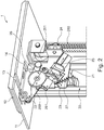
- FIG. 2 the operating mechanism 2 of the extractor device 1 is shown in detail.
- the cover flap 12 is in the Figure 2 in the idle state.
- a four-point hinge 22 is attached to the underside of the cover plate 12.
- the longitudinal ends of two legs of the joint 22 are rotatably attached to the underside of the cover plate 12.
- the opposite longitudinal ends of the two legs of the joint 22 are indirectly connected to the slide 21.
- the joint 22 is connected to the slide 21 via a base plate 23 and a gear 26.
- One of the legs of the joint 22 is rotatably attached to the base plate 23.
- the further leg is connected to a gear 260 of the gear 26.
- the gear 26 is a worm gear, which consists of a gear 260 and a worm 261.
- the worm 261 is driven by a motor 25 which is fixed on the base plate 23.
- the base plate 23 is rotatably connected to the carriage 21.
- the base plate 23 is connected to the carriage 21 via a spring 27 in the embodiment shown.
- a driver 24 is formed on the base plate 23. In the embodiment shown, this represents an angled web.
- the driver 24 engages with a drive 28.
- the drive 28 comprises a drive motor 281 and a flexible drive element.
- the drive element represents a toothed belt 280.
- the toothed belt 280 extends vertically and can be moved by the drive motor 281.
- the driver 24 can engage with the toothed belt 280 via a clamp. As a result, the carriage 21 is moved vertically in the guide 20 via the driver 24 and the base plate 23.
- the cover flap 12 can be moved downward via the output 28.
- the toothed belt 260 is driven by the drive motor 261.
- the carriage 21 is thereby moved downward in the guide 20 via the driver 24. This is in Figure 5 shown schematically.
- the cover flap 12 is moved downwards at least until the front edge of the cover flap 12 lies below the cover plate 11. This is in Figure 6 shown.
- the operation of the cover flap 12 can be described as follows.
- the motor-driven four-point joint 22 sets the rotary movement of the gear 26 in one Swivel motion around.
- the cover flap 12 lies on the suction opening 10, which can also be referred to as an air suction opening.
- the base plate 23 is rotatably mounted on the carriage 21.
- the spring 27 and the weight of the cover flap 12 ensure that the transmission 26, which is a worm gear, is positively connected. If the cover flap 12 is blocked when closing, the gear 260 of the worm gear 26 disengages from the worm 261 and prevents fingers or other objects from being pinched.
- the driver 24 couples the base plate 23 to the toothed belt 280.
- the toothed belt 280 instead of the toothed belt 280, another flexible construction, such as, for example, a V-belt or a rope, can be used.
- the drive 280 is preferably also used to move another part of the extractor device.
- the drive 28 can be used to move air guiding elements (not shown).
- the up and down movement of the vertically lying cover flap 12 represents an opposite direction of movement to the direction of movement of the air guiding elements.
- the air guiding elements can in particular represent two disks which can be moved in and out through the recesses 15 in front of and behind the suction opening 10 and so that the air can suck in in a plane above the suction opening 10.
- the present invention thus provides a cover flap which rests on the suction opening in a position which can also be referred to as the rest position and which is movable from this position and can be lowered into the extractor device in the vertical orientation. Cooking fumes are drawn off in the vertically downward direction with the extractor device according to the invention.
- the extractor device can therefore also be referred to as downdraft.
- the fume extraction device can also have other suction devices, for example a suction drawer, which is extended from an opening in the fume extraction device. In this embodiment, too, the suction opening is covered upward by the cover flap in the rest position.
- movable air guiding elements which can also be referred to as a movable glass design or movable glass panes, are provided, these are retracted into the fume extraction device in the rest position and the cutouts through which these are retracted and extended are through the cover flap covered.
- the extractor device can also be an extractor device that has no additional air guiding elements. In this embodiment, the air is sucked directly into the suction opening.
- the cover flap can be driven manually or by motor and, additionally or alternatively, can also be driven by the movement of the glass design.
- the extractor hood device can be arranged in or on a hob.
- the cover flap can be a frameless flap that can be made of glass, for example.
- the present invention has a number of advantages.
- the cover flap seals the suction opening in the rest position.
- the extractor hood device can be integrated in or on a hob. In the rest position, in particular, there are only a few columns.
- the cover flap can represent an attached flap.
- a pinch protection for fingers and objects can be implemented in a simple manner.
Landscapes
- Engineering & Computer Science (AREA)
- Chemical & Material Sciences (AREA)
- Combustion & Propulsion (AREA)
- Mechanical Engineering (AREA)
- General Engineering & Computer Science (AREA)
- Ventilation (AREA)
Abstract
Description
- Die vorliegende Erfindung betrifft eine Dunstabzugsvorrichtung sowie eine Küchenvorrichtung mit einer solchen Dunstabzugsvorrichtung.
- Zum Absaugen von Dünsten und Wrasen, die beim Kochen entstehen, ist es bekannt, Dunstabzugsvorrichtungen einzusetzen. Eine Dunstabzugsvorrichtung kann beispielsweise eine Dunstabzugshaube sein, die oberhalb des Kochfeldes an einer Raumwand oder Raumdecke montiert wird. Zudem sind Dunstabzugsvorrichtungen bekannt, die die Luft von dem Kochfeld nach unten absaugen. Diese Dunstabzugsvorrichtungen werden auch als Downdraft bezeichnet. Die Absaugöffnung dieser Downdrafts kann in der Vertikalen an einen vertikal verfahrbaren Absaugkörper liegen. Eine solche Dunstabzugsvorrichtung ist beispielsweise in der
DE 10 2010 042 436 A1 beschrieben. Ein Nachteil dieser Dunstabzugsvorrichtung besteht darin, dass das gesamte Gehäuse der Dunstabzugsvorrichtung ausgefahren werden muss und daher ein großes Gewicht bewegt werden muss. Zudem wirkt das Gehäuse als optische Blockade. Weiterhin sind Dunstabzugsvorrichtungen bekannt, bei denen die Ansaugöffnung in der Horizontalen benachbart zu einem Kochfeld liegt. Diese Dunstabzugsvorrichtungen werden auch als Tischlüfter oder Muldenlüfter bezeichnet. Eine solche Dunstabzugsvorrichtung ist beispielsweise in derDE 10 2005 030 038 A1 beschrieben. Hierbei kann die Dunstabzugsvorrichtung ein Luftleitelement aufweisen, das die Ansaugöffnung der Dunstabzugsvorrichtung durch Aufliegen verschließen kann und das beim Betrieb der Dunstabzugsvorrichtung nach oben aufgeschwenkt werden kann. Ein Nachteil dieser Dunstabzugsvorrichtung besteht darin, dass das Luftleitelement beim Betrieb der Dunstabzugsvorrichtung nach oben weg steht und den Benutzer damit behindern kann. Zudem ist der Betrag, um den das Luftleitelement nach oben über die Ebene des Kochfeldes übersteht, durch die Tiefe des Luftleitelementes begrenzt. - Aufgabe der vorliegenden Erfindung ist es daher eine Lösung zu schaffen, die zum einen ein verbessertes optisches Erscheinungsbild aufweist und die zum anderen ein zuverlässiges Absaugen von Dünsten und Wrasen von einem Kochfeld und einfaches und sicheres Handhaben der Dunstabzugsvorrichtung erlaubt.
- Gemäß einem ersten Aspekt wird die Aufgabe gelöst durch eine Dunstabzugsvorrichtung für ein Kochfeld, die eine Absaugöffnung und mindestens eine Abdeckklappe für die Absaugöffnung aufweist. Die Dunstabzugsvorrichtung ist dadurch gekennzeichnet, dass die Dunstabzugsvorrichtung eine vertikal verlaufende Führung für die Abdeckplatte aufweist, die unterhalb der Absaugöffnung angeordnet ist und die Dunstabzugsvorrichtung einen Schlitten aufweist, der an der Führung verschiebbar gelagert ist und die Abdeckklappe über ein Gelenk schwenkbar mit dem Schlitten verbunden ist.
- Die Dunstabzugsvorrichtung stellt eine Vorrichtung dar, mittels derer Luft von einem Kochfeld nach unten abgesaugt werden kann. Die Dunstabzugsvorrichtung weist daher eine Absaugöffnung auf, die im Folgenden auch als Ansaugöffnung bezeichnet wird. Die Absaugöffnung liegt vorzugsweise in der Horizontalen. Besonders bevorzugt weist die Dunstabzugsvorrichtung eine Deckplatte auf, in die die Absaugöffnung eingebracht ist. Die Deckplatte kann Teil des Kochfeldes, insbesondere ein Bereich der Kochfeldplatte sein, oder zu dem Kochfeld benachbart angeordnet sein. Die Deckplatte liegt im montierten Zustand in der Horizontalen. Die Absaugöffnung stellt vorzugsweise eine längliche Aussparung dar. Die Absaugöffnung erstreckt sich dabei vorzugsweise parallel zu einem Rand des Kochfeldes. Die Dunstabzugsvorrichtung weist mindestens eine Abdeckklappe für die Absaugöffnung auf. Die Abdeckklappe wird im Folgenden auch einfach als Klappe bezeichnet. Die Abdeckkappe stellt ein plattenförmiges Element dar, das vorzugsweise eben ist. Die Größe der Abdeckklappe ist so ausgelegt, dass diese zumindest die Absaugöffnung der Dunstabzugsvorrichtung abdecken kann. Sind mehrere Abdeckklappen vorgesehen, so ist die Größe der einzelnen Abdeckklappen so gewählt, dass diese gemeinsam zumindest die Absaugöffnung abdecken können. Die Abdeckklappe liegt im Ruhezustand, das heißt dem Zustand, in dem diese die Absaugöffnung abdeckt, dabei vorzugsweise auf der Oberseite der Deckplatte, in die die Absaugöffnung eingebracht ist, auf. Der Ruhezustand wird auch geschlossene Zustand bezeichnet.
- Die Dunstabzugsvorrichtung kann mindestens ein Gebläse aufweisen oder mit einem Gebläse verbunden sein, über das Luft in die Absaugöffnung eingesaugt wird.
- Die Dunstabzugsvorrichtung weist eine vertikal verlaufende Führung für die Abdeckplatte auf, die unterhalb der Absaugöffnung angeordnet ist. Die Führung kann eine oder mehrere Schienen umfassen, die jeweils vertikal ausgerichtet sind. Die Führung kann an deren Oberseite an der Deckplatte der Dunstabzugsvorrichtung befestigt sein. Es liegt aber auch im Rahmen der Erfindung, dass die Führung an einem Gehäuse der Dunstabzugsvorrichtung befestigt ist, das sich unterhalb der Deckplatte erstreckt. Hierbei ist die Führung vorzugsweise an einer Seitenwand des Gehäuses befestigt. Vorzugsweise sind in der Dunstabzugsvorrichtung mindestens zwei Führungen vorgesehen, die an gegenüberliegenden Längsenden der Dunstabzugsvorrichtung angeordnet sind. Insbesondere können die Führungen an gegenüberliegenden Seitenwänden des Gehäuses der Dunstabzugsvorrichtung befestigt sein.
- Die Dunstabzugsvorrichtung weist weiterhin einen Schlitten auf, der an der Führung verschiebbar gelagert ist. Sind mehrere Führungen vorgesehen, so ist vorzugsweise an jeder der Führungen jeweils ein Schlitten verschiebbar gelagert. Der Schlitten kann auch als Schuh bezeichnet werden. Stellt die Führung eine Schienenkonstruktion dar, die zwei Schienen umfasst, die mit deren offenen Seiten einander zugewandt sind, so wird der Schlitten in die offenen Seiten der Schienen eingeführt und so an der Führung gehalten. Der Schlitten kann dabei in Längsrichtung der Führung, insbesondere in Längsrichtung der Schienen in diesen verschoben werden. Die Führung verläuft vertikal, das heißt erstreckt sich in der Vertikalen. Somit kann der Schlitten in der Führung nach oben oder unten verschoben werden.
- Die Führung ist unterhalb der Absaugöffnung angeordnet. Dies bedeutet, dass die Führung zu der Ebene, in der die Absaugöffnung liegt, nach unten versetzt angeordnet ist. Weist die Dunstabzugsvorrichtung eine Deckplatte auf, so liegt die Führung unter der Deckplatte der Dunstabzugsvorrichtung. In der senkrechten Draufsicht auf die Absaugöffnung liegt die Führung vorzugsweise zu der Absaugöffnung nach außen versetzt. Sind zwei Führungen vorgesehen, so liegen diese vorzugsweise jeweils zu einem Längsende der Absaugöffnung nach außen versetzt.
- Erfindungsgemäß ist die Abdeckklappe über ein Gelenk schwenkbar mit dem Schlitten verbunden. Die Verbindung zwischen Schlitten und Gelenk kann mittelbar oder unmittelbar sein. Bei der unmittelbaren Verbindung ist das Gelenk an dem Schlitten befestigt. Bei der mittelbaren Verbindung ist, das Gelenk über ein Zwischenstück, insbesondere eine Basisplatte, an dem Schlitten befestigt. Das Gelenk ist vorzugsweise an der Unterseite der Abdeckklappe befestigt. Das Gelenk kann dabei beispielsweise an einem Verbindungsstück, das an die Unterseite der Abdeckklappe angeklebt ist befestigt sein. Insbesondere können die Enden von Schenkeln des Gelenks an diesem Verbindungsstück drehbar befestigt sein. Über das Gelenk kann die Abdeckklappe aus der Horizontalen nach oben verschwenkt, das heißt geöffnet werden, und aus einer Position, in der die Abdeckklappe nach oben verschwenkt ist, in die Horizontale verschwenkt, das heißt geschlossen werden. Die Position, in der die Abdeckklappe in der Horizontalen liegt und dabei die Absaugöffnung abdeckt, wird im Folgenden auch als Ruheposition, Ruhezustand oder als geschlossene Position oder geschlossener Zustand bezeichnet. Die Position, in der die Abdeckklappe aus der Horizontalen nach oben verschwenkt ist, wird auch als Betriebsposition, Betriebszustand oder als geöffnete Position oder geöffneter Zustand bezeichnet. Eine der Betriebspositionen, nämlich die Position, in der die Abdeckklappe in der Vertikalen liegt, wird als Betriebsendposition oder Betriebsendzustand bezeichnet.
- Richtungsangaben, wie oben und unten beziehen sich, soweit nicht anders angegeben, auf die Dunstabzugsvorrichtung in dem montierten Zustand. In dem montierten Zustand ist die Dunstabzugsvorrichtung in oder an ein Kochfeld oder in eine Arbeitsplatte einer Küche eingebaut und die Absaugöffnung liegt vorzugsweise in Horizontalen oder geringfügig zu der Horizontalen geneigt.
- Indem die erfindungsgemäße Dunstabzugsvorrichtung mindestens eine Abdeckklappe aufweist und die Abdeckklappe zum einen durch die Führung in vertikaler Richtung bewegt und zum anderen über das Gelenk verschwenkt werden kann, wird eine Reihe von Vorteilen erzielt. Insbesondere kann die Abdeckklappe sowohl in vertikaler Richtung bewegt werden als auch um eine horizontale Drehachse verschwenkt werden. Hierdurch kann die Absaugöffnung der Dunstabzugsvorrichtung zeitweise durch die Abdeckklappe abgedeckt, das heißt verschlossen, werden und die Abdeckklappe aus dem geschlossenen Zustand in einen geöffneten Zustand gebracht werden. Zudem kann die Abdeckklappe insbesondere in einem geöffneten Zustand, insbesondere dem Betriebsendzustand, in dem die Abdeckklappe vertikal ausgerichtet ist, vertikal verschoben beziehungsweise verfahren werden. Insbesondere kann die Abdeckklappe dadurch in eine Position gebracht werden, in der diese vollständig unterhalb der Absaugöffnung liegt. Diese Position, in der die Abdeckklappe in der Dunstabzugsvorrichtung aufgenommen ist, wird auch als Einfahrposition bezeichnet. Diese Einfahrposition wird eingestellt, wenn die Dunstabzugsvorrichtung betrieben wird, das heißt, wenn über die Absaugöffnung Luft in die Dunstabzugsvorrichtung eingesaugt wird. Ist eine Deckplatte vorgesehen, so ist in dieser Deckplatte vorzugsweise ein Einführschlitz vorgesehen, durch den die Abdeckklappe bei der vertikalen Bewegung geführt werden kann. Über den Einführschlitz kann die Abdeckklappe in die Dunstabzugsvorrichtung eingefahren werden, das heißt in die Einfahrposition gebracht werden, und aus dieser ausgefahren werden, insbesondere in eine Position gebracht werden, in der die Abdeckklappe vollständig oberhalb der Deckplatte liegt. Beim Einfahren und Ausfahren liegt die Abdeckklappe vorzugsweise in der Vertikalen. Aus der ausgefahrenen Position kann die Abdeckklappe über das Gelenk verschwenkt werden, um in die Ruheposition gebracht zu werden, in der diese die Absaugöffnung abdeckt.
- Die Abdeckklappe liegt im Ruhezustand in der Horizontalen und ist daher für den Benutzer kaum sichtbar. Im der Einfahrposition, die auch als eingefahrener Zustand bezeichnet werden kann, liegt die Abdeckklappe unterhalb der Absaugöffnung und ist somit für den Benutzer ebenfalls nicht sichtbar. Daher weist die Dunstabzugsvorrichtung ein verbessertes optisches Erscheinungsbild auf. Indem die Absaugöffnung in dem Ruhezustand durch die Abdeckklappe verschlossen werden kann, kann das Eintreten von Verunreinigungen in die Absaugöffnung verhindert werden. Dadurch können die Bestandteile der Dunstabzugsvorrichtung geschützt werden und somit ein sicheres Handhaben der Dunstabzugsvorrichtung ermöglicht werden. Indem das vertikale Verschieben und das Verschwenken der Abdeckklappe bei der erfindungsgemäßen Dunstabzugsvorrichtung über eine gemeinsame Betätigungsvorrichtung, die die Führung, den Schlitten und das Gelenk umfasst, durchgeführt wird, ist der Aufbau der Dunstabzugsvorrichtung und damit auch deren Handhabung vereinfacht.
- Gemäß einer bevorzugten Ausführungsform stellt das Gelenk ein Vierpunkt-Gelenk dar. Durch die Verwendung eines Vierpunkt-Gelenkes kann die Abdeckklappe entlang einer Bahnkurve verschwenkt werden. Somit kann die Abdeckklappe aus einer Ruhestellung, in der diese die Absaugöffnung abdeckt in eine vertikale Stellung gebracht werden, ohne, dass die Abdeckklappe an dem Rand des Einführschlitzes anstößt. Das Vierpunkt-Gelenk ist vorzugsweise durch zwei Schenkel gebildet, wobei jeder der Schenkel mit einem Ende an der Abdeckklappe, insbesondere einem Verbindungsstück an der Unterseite der Abdeckklappe, und mit dem anderen Ende an dem Schlitten, vorzugsweise mittelbar über eine Basisplatte an dem Schlitten befestigt ist.
- Vorzugsweise ist das Gelenk über ein Schneckengetriebe mit dem Schlitten verbunden. Das Schneckengetriebe weist vorzugsweise ein Zahnrad und eine Schnecke auf, die mit dem Zahnrad eingreift. Vorzugsweise ist die Schnecke an dem Schlitten und besonders bevorzugt an einem Zwischenelement, insbesondere einer Basisplatte, befestigt. Das Zahnrad ist mit dem Gelenk und insbesondere mit einem Schenkelende eines Vierpunkt-Gelenkes verbunden. Durch die Verwendung eines Schneckengetriebes kann der Vorteil erzielt werden, dass die Teile des Getriebes außer Eingriff gebracht werden können und damit eine Schwenkbewegung der Abdeckklappe beendet werden kann. Insbesondere geht bei einem Blockieren der Abdeckklappe beim Verschwenken in den geschlossenen Zustand das Zahnrad aus dem Eingriff mit der Schnecke. Das Blockieren der Abdeccklappe kann beispielsweise auftreten, wenn ein Finger oder ein anderer Gegenstand zwischen der Klappe und der Absaugöffnung oder der Klappe und der Deckplatte liegt. Somit kann auf einfache Weise ein Einklemmschutz geschaffen werden, durch den die Handhabung der Dunstabzugsvorrichtung noch sicherer wird.
- Gemäß einer weiteren bevorzugten Ausführungsform ist an dem Schlitten eine Basisplatte drehbar befestigt und das Gelenk ist an der Basisplatte befestigt. Als Basisplatte wird ein Zwischenelement bezeichnet, das zur Verbindung zwischen dem Schlitten und dem Gelenk vorgesehen ist. An der Basisplatte kann zudem ein Verbindungselement zur Verbindung der Basisplatte mit einem vertikalen Antrieb, insbesondere einem Antrieb einer Bewegungsvorrichtung zur vertikalen Bewegung der Abdeckklappe, vorgesehen sein. Die Basisplatte ist an dem Schlitten drehbar befestigt. Insbesondere ist die Basisplatte um eine Drehachse, die in der Horizontalen liegt und zu der Seite des Schlittens an dem diese befestigt ist, senkrecht steht, drehbar. Dies bedeutet, dass die Basisplatte in einer Ebene parallel zu der Oberfläche des Schlittens, an dem die Basisplatte befestigt ist, gedreht werden kann. Die Drehung der Basisplatte wird vorzugsweise durch dessen Verbindung mit dem vertikalen Antrieb und durch mindestens ein Federelement begrenzt. Zudem können an dem Schlitten und/oder der Basisplatte Anschläge vorgesehen sein, die die Drehung der Basisplatte weiter einschränken.
- Gemäß einer bevorzugten Ausführungsform weist die Basisplatte einen Mitnehmer auf, der in einen vertikalen Antrieb eingreift. Der Mitnehmer ist insbesondere an der Basisplatte, die mit dem Schlitten verbunden ist, ausgebildet. Insbesondere kann der Mitnehmer einen Abbug eines Teils des Randes der Basisplatte darstellen, an dem beispielsweise ein Klemmelement lösbar befestigt ist. Das Klemmelement klemmt im montierten Zustand ein bewegliches Teil des vertikalen Antriebs ein. Hierdurch wird bei einer Bewegung des vertikalen Antriebs, die Basisplatte und damit der Schlitten ebenfalls in vertikaler Richtung mitbewegt. Hierdurch kann die Abdeckklappe ein- und ausgefahren werden. Den Vorteil, den das Vorsehen eines Mitnehmers im Eingriff mit einem vertikalen Antrieb aufweist, ist, dass der vertikale Antrieb für andere Zwecke in der Dunstabzugsvorrichtung vorgesehen sein oder verwendet werden kann und gleichzeitig zum vertikalen Bewegen der Abdeccklappe dienen kann. Insbesondere kann der vertikale Antrieb mit dem der Mitnehmer eingreift, vorgesehen sein, um Luftleitelemente, die an der Absaugöffnung ein- oder ausgefahren werden sollen, zu bewegen.
- Gemäß einer bevorzugten Ausführungsform weist der vertikale Antrieb eine flexible Konstruktion, insbesondere einen Zahnriemen, Keilriemen oder ein Seil auf. Durch die Flexibilität des Antriebs kann eine gewisse Bewegung der Basisplatte, insbesondere eine Drehung der Basisplatte erfolgen, ohne, dass der Mitnehmer aus dem Eingriff mit dem Antrieb kommt. Eine solche Drehung tritt beispielsweise auf, wenn die Abdeckklappe blockiert wird.
- Der vertikale Antrieb kann einen Antriebsmotor aufweisen, durch den das flexible Antriebselement, insbesondere der Zahnriemen bewegt wird.
- Gemäß einer bevorzugten Ausführungsform weist die Dunstabzugsvorrichtung einen Motor auf, der das Gelenk an der Abdeckklappe bewegt und der vorzugsweise das Schneckengetriebe antreibt. Der Motor ist vorzugsweise auf der Basisplatte montiert. Mit dem Motor ist die Schnecke des Schneckengetriebes verbunden. Dadurch wird das Zahnrad, das mit der Schnecke in Eingriff steht gedreht und bewegt dadurch den mit dem Zahnrad verbundenen Schenkel des Vierpunkt-Gelenkes, wodurch die Abdeckklappe geschwenkt wird.
- Gemäß einer Ausführungsform weist die Dunstabzugsvorrichtung ein Federelement auf, das an die drehbare Basisplatte so angreift, dass eine mit der Basisplatte verbundene Komponente des Getriebes gegen die andere Komponente, die mit dem Gelenk verbunden ist, gedrückt wird.
- Gemäß einer weiteren Ausführungsform weist die Dunstabzugsvorrichtung eine Deckplatte auf, die einen Einführschlitz für die Abdeckklappe aufweist, der zu der Absaugöffnung der Dunstabzugsvorrichtung benachbart liegt. Der Einführschlitz liegt vorzugsweise parallel zu der Absaugöffnung und erstreckt sich in der Längsrichtung der länglichen Absaugöffnung. Indem ein Einführschlitz vorgesehen ist, kann die Abdeckklappe während der Bewegung, insbesondere während des vertikalen Verfahrens zusätzlich geführt werden.
- Gemäß einer weiteren Ausführungsform weist die Dunstabzugsvorrichtung zumindest ein Luftleitelement auf, das in vertikaler Richtung verschiebbar ist. Das Luftleitelement kann insbesondere eine Glasplatte darstellen und wird daher auch als Scheibe bezeichnet. Das Luftleitelement ist vorzugsweise zu der Absaugöffnung benachbart angeordnet und erstreckt sich parallel zu der Absaugöffnung in der Vertikalen. Das Luftleitelement kann zwischen der Absaugöffnung und dem Einführschlitz für die Abdeckklappe angeordnet sein. Es liegt allerdings auch im Rahmen der Erfindung, dass zusätzlich oder alternativ ein Luftleitelement auf der Seite der Absaugöffnung angeordnet ist, die dem Einführschlitz abgewandt ist. Besonders bevorzugt ist das Luftleitelement so angeordnet, dass die Abdeccklappe in der Ruheposition die Aussparung, durch die das Luftleitelement in die Dunstabzugsvorrichtung eingefahren wird, nach oben abdeckt.
- Durch das mindestens eine Luftleitelement kann Luft während des Kochvorgangs gezielt zu der Absaugöffnung geleitet werden. Indem die Abdeckklappe auch die Aussparung, durch die das Luftleitelement eingefahren wird, abdeckt, weist die Dunstabzugsvorrichtung ein verbessertes optisches Erscheinungsbild auf. Zudem kann das Eintreten von Verunreinigungen in die Aussparung für das Luftleitelement verhindert werden.
- Gemäß einem weiteren Aspekt betrifft die Erfindung eine Küchenvorrichtung, die ein Kochfeld und mindestens eine erfindungsgemäße Dunstabzugsvorrichtung aufweist.
- Vorteile und Merkmale, die bezüglich der Dunstabzugsvorrichtung beschrieben werden, gelten - soweit anwendbar - entsprechend für die Küchenvorrichtung und umgekehrt.
- Die Küchenvorrichtung kann so ausgestaltet sein, dass die Dunstabzugsvorrichtung in das Kochfeld integriert ist. Alternativ kann die Dunstabzugsvorrichtung aber auch separat zu dem Kochfeld montiert sein. In diesem Fall ist die Dunstabzugsvorrichtung vorzugsweise in der Nähe des Kochfeldes montiert und liegt vorzugsweise an einem Rand des Kochfeldes an.
- Die Erfindung wird im Folgenden anhand der beiliegenden Zeichnungen erneut erläutert. Es zeigen:
-
Figur 1 : eine schematische Perspektivansicht einer Ausführungsform der erfindungsgemäßen Dunstabzugsvorrichtung im eingefahrenen Zustand; -
Figur 2 : eine schematische Detailansicht des Betätigungsmechanismus der Ausführungsform nachFigur 1 im geschlossenen Zustand; -
Figur 3 : eine schematische Detailansicht des Betätigungsmechanismus der Ausführungsform nachFigur 1 in einem Betriebszustand; -
Figur 4 : eine schematische Detailansicht des Betätigungsmechanismus der Ausführungsform nachFigur 1 in einem Betriebsendzustand; -
Figur 5 : eine schematische Detailansicht des Betätigungsmechanismus der Ausführungsform nachFigur 1 in einem teilweise eingefahrenen Zustand; und -
Figur 6 : eine schematische Detailansicht des Betätigungsmechanismus der Ausführungsform nachFigur 1 in einem vollständig eingefahrenen Zustand. -
Figur 1 zeigt eine schematische Perspektivansicht einer Ausführungsform der erfindungsgemäßen Dunstabzugsvorrichtung 1. In der gezeigten Ansicht sind das Gebläse, das Gehäuse sowie die Luftführung der Dunstabzugsvorrichtung 1 nicht gezeigt. Die Dunstabzugsvorrichtung 1 weist eine Deckplatte 11, eine Abdeckklappe 12 und einen Betätigungsmechanismus 2 auf. Die Deckplatte 11 ist im montierten Zustand vorzugsweise benachbart oder integriert in einem Kochfeld (nicht gezeigt) angeordnet. Die Deckplatte 11 weist eine längliche Form auf. In der Deckplatte 11 ist die Absaugöffnung 10 eingebracht. Über die Absaugöffnung 10 wird Luft in die Dunstabzugsvorrichtung 1 eingesaugt. Zusätzlich ist in der Deckplatte 11 ein Einführschlitz 13 eingebracht. Der Einführschlitz 13 erstreckt sich parallel zu der Ansaugöffnung 10. In der Nähe des Längsendes des Einführschlitzes 13 ist ein Gelenkschlitz 14 eingebracht. Der Gelenkschlitz 14 erstreckt sich senkrecht zu dem Einführschlitz 13. Zudem sind in der gezeigten Ausführungsform zwei Aussparungen 15 eingebracht. Durch die Aussparungen 15 können Luftleitelemente (nicht gezeigt), die auch als Scheiben bezeichnet werden können, aus der Dunstabzugsvorrichtung 1 über die Deckplatte 11 nach oben ausgefahren und in die Dunstabzugsvorrichtung 1 eingefahren werden. - In der gezeigten Ausführungsform ist an der Unterseite der Deckplatte 11 ein Betätigungsmechanismus 2 angebracht. Der Betätigungsmechanismus 2 kann aber auch an der Seitenwand eines Gehäuses (nicht gezeigt) der Dunstabzugsvorrichtung 1 befestigt sein. Der Betätigungsmechanismus 2 umfasst eine Führung 20 und einen Schlitten 21. Die Führung 20 liegt unterhalb der Deckplatte 11 und erstreckt sich vertikal. In der gezeigten Ausführungsform stellt die Führung 10 eine Doppelschiene dar, die an beiden Längsseiten jeweils eine U-förmige Schiene aufweist, deren offenen Seiten einander zugewandt sind. Der Schlitten 21 ist in der Führung 10 aufgenommen und kann in der Führung 10 in vertikaler Richtung nach oben und unten verschoben werden. Mit dem Schlitten 21 ist die Abdeckklappe 12 der Dunstabzugsvorrichtung 1 verbunden.
- In der
Figur 1 ist die Abdeckklappe 12 in der eingefahrenen Position gezeigt. In dieser Position liegt die Abdeckklappe 12 in der Vertikalen und unterhalb der Deckplatte 11. - In
Figur 2 ist der Betätigungsmechanismus 2 der Dunstabzugsvorrichtung 1 im Detail gezeigt. Die Abdeckklappe 12 befindet sich in derFigur 2 in dem Ruhezustand. An der Unterseite der Abdeckplatte 12 ist ein Vierpunkt-Gelenk 22 befestigt. Insbesondere sind die Längsenden von zwei Schenkeln des Gelenks 22 an der Unterseite der Abdeckplatte 12 drehbar befestigt. Die gegenüberliegenden Längsenden der zwei Schenkel des Gelenks 22 sind mit dem Schlitten 21 indirekt verbunden. Insbesondere ist das Gelenk 22 über eine Basisplatte 23 und ein Getriebe 26 mit dem Schlitten 21 verbunden. Einer der Schenkel des Gelenks 22 ist an der Basisplatte 23 drehbar befestigt. Der weitere Schenkel ist mit einem Zahnrad 260 des Getriebes 26 verbunden. Das Getriebe 26 stellt ein Schneckengetriebe dar, das aus einem Zahnrad 260 und eine Schnecke 261 besteht. Die Schnecke 261 wird durch einen Motor 25 angetrieben, der auf der Basisplatte 23 befestigt ist. - Die Basisplatte 23 ist drehbar mit dem Schlitten 21 verbunden. Zudem wird die Basisplatte 23 in der gezeigten Ausführungsform über eine Feder 27 mit dem Schlitten 21 verbunden.
- An einem Seitenrand der Basisplatte 23 ist an der Basisplatte 23 ein Mitnehmer 24 ausgebildet. Dieser stellt in der dargestellten Ausführungsform einen abgewinkelten Steg dar. Der Mitnehmer 24 greift mit einem Antrieb 28 ein. Der Antrieb 28 umfasst einen Antriebsmotor 281 und ein flexibles Antriebselement. Das Antriebselement stellt in der gezeigten Ausführungsform einen Zahnriemen 280 dar. Der Zahnriemen 280 erstreckt sich in der Vertikalen und kann durch den Antriebsmotor 281 bewegt werden. Der Mitnehmer 24 kann über eine Klemme mit dem Zahnriemen 280 eingreifen. Hierdurch wird über den Mitnehmer 24 und die Basisplatte 23 der Schlitten 21 in der Führung 20 vertikal bewegt.
- Wird die Schnecke 261 durch den Motor 25 angetrieben, wird das Zahnrad 260, das mit der Schnecke 261 eingreift, gedreht. Hierdurch wird die Abdeckklappe 12 über das Gelenk 22 aus der Ruheposition nach oben verschwenkt. Dies ist in
Figur 3 schematisch gezeigt. Durch das Vierpunkt-Gelenk 22 wird die Abdeckklappe 12 dabei zusätzlich zu der Schwenkbewegung nach oben angehoben. Die Schenkel des Gelenks 22 ragen dabei durch den Gelenkschlitz 14 hindurch. Wird die Abdeckklappe 12 weiter nach oben verschwenkt, so gelangt diese in die Vertikale. Diese Position, die als Betriebsendposition bezeichnet wird, ist inFigur 4 gezeigt. In derFigur 4 liegt das hintere Ende der Abdeccklappe 12 in den Einführschlitz 13. - Aus dieser Position kann die Abdeckklappe 12 über den Abtrieb 28 nach unten bewegt werden. Hierzu wird der Zahnriemen 260 über den Antriebsmotor 261 angetrieben. Über den Mitnehmer 24 wird dadurch der Schlitten 21 in der Führung 20 nach unten verschoben. Dies ist in
Figur 5 schematisch gezeigt. - Die Abdeckklappe 12 wird zumindest soweit nach unten verfahren, bis der vordere Rand der Abdeckklappe 12 unterhalb der Deckplatte 11 liegt. Dies ist in
Figur 6 gezeigt. - Die Betätigung der Abdeckklapp 12 kann wie folgt beschrieben werden. In der Führung 10 gleitet der Schlitten 21, auf dem die drehbare Basisplatte 23 montiert ist. Das motorisch angetriebene Vierpunkt-Gelenk 22 setzt die Drehbewegung des Getriebes 26 in eine Schwenkbewegung um. Die Abdeckklappe 12 legt sich auf die Absaugöffnung 10, die auch als Luftabsaugöffnung bezeichnet werden kann. Beim Öffnen der Abdeckklappe 12 schwenkt diese in eine senkrechte Stellung. Die Basisplatte 23 ist drehbar auf dem Schlitten 21 gelagert. Durch die Feder 27 sowie das Eigengewicht der Abdeckklappe 12 wird ein Kraftschluss des Getriebes 26, das ein Schneckengetriebes darstellt, gewährleistet. Sollte die Abdeckklappe 12 beim Schließen blockiert werden, geht das Zahnrad 260 des Schneckengetriebes 26 außer Eingriff mit der Schnecke 261 und verhindert das Klemmen von Fingern oder anderer Gegenstände. Der Mitnehmer 24 koppelt die Basisplatte 23 an den Zahnriemen 280. Statt des Zahnriemens 280 kann auch eine andere flexible Konstruktion, wie beispielsweise ein Keilriemen oder ein Seil verwendet werden. Vorzugsweise dient der Antrieb 280 zusätzlich zur Bewegung eines weiteren Teils der Dunstabzugsvorrichtung. Beispielsweise kann der Antrieb 28 zum Bewegen von Luftleitelementen (nicht gezeigt) dienen. In diesem Fall stellt die Auf- und Abbewegung der vertikal liegenden Abdeckklappe 12 eine gegenläufige Bewegungsrichtung zu der Bewegungsrichtung der Luftleitelemente dar. Die Luftleitelemente können insbesondere zwei Scheiben darstellen, die vor und hinter der Absaugöffnung 10 durch die Aussparungen 15 ein- und ausgefahren werden können und damit die Luft in einer Ebene oberhalb der Absaugöffnung 10 einsaugen können.
- Mit der vorliegenden Erfindung wird somit eine Abdeckklappe bereitgestellt, die in einer Position, die auch als Ruheposition bezeichnet werden kann, auf der Absaugöffnung aufliegt und aus dieser Position bewegliche ist und in die Dunstabzugsvorrichtung in der vertikalen Ausrichtung versenkbar ist. Mit der erfindungsgemäßen Dunstabzugsvorrichtung Kochdünsten in vertikal nach unten weisender Richtung abgesogen. Die Dunstabzugsvorrichtung kann daher auch als Downdraft bezeichnet werden. Obwohl die Erfindung anhand einer Ausführungsform beschrieben wurde, bei der zur Luftleitung Luftleitelemente, insbesondere Scheiben ausfahrbar vorgesehen sein können, kann die Dunstabzugsvorrichtung auch andere Absaugvorrichtungen, beispielsweise eine Absaugschublade aufweisen, die aus einer Öffnung in der Dunstabzugsvorrichtung ausgefahren wird. Auch bei dieser Ausführungsform wird die Absaugöffnung durch die Abdeckklappe in der Ruheposition nach oben abgedeckt. Sind bewegliche Luftleitelemente, die auch als bewegliches Glasdesign oder bewegliche Glasscheiben bezeichnet werden können vorgesehen, so sind diese in der Ruheposition in die Dunstabzugsvorrichtung eingefahren und die Aussparungen, durch die diese ein- und ausgefahren werden, sind durch die Abdeckklappe abgedeckt. Die Dunstabzugsvorrichtung kann aber auch eine Dunstabzugsvorrichtung darstellen, die keine zusätzlichen Luftleitelemente aufweist. In dieser Ausführungsform wird die Luft direkt in die Absaugöffnung eingesaugt. Die Abdeckklappe kann manuell oder motorisch angetrieben werden und zusätzlich oder alternativ auch durch die Bewegung des Glasdesigns angetrieben werden. Die Dunstabzugsvorrichtung kann in oder an einem Kochfeld angeordnet sein. Die Abdeckklappe kann eine rahmenlose Klappe darstellen, die beispielsweise aus Glas bestehen kann.
- Die vorliegende Erfindung weist eine Reihe von Vorteilen auf. Insbesondere dichtet die Abdeckklappe in der Ruheposition die Absaugöffnung ab. Zudem kann die Dunstabzugsvorrichtung in oder an ein Kochfeld integriert werden. Insbesondere in der Ruheposition liegen dann nur wenige Spalten vor. Die Abdeckklappe kann eine aufgesetzte Klappe darstellen. Zudem kann mit der erfindungsgemäßen Dunstabzugsvorrichtung auf einfache Weise ein Klemmschutz für Fingern und Gegenständen realisiert werden.
-
- 1
- Dunstabzugsvorrichtung
- 10
- Absaugöffnung
- 11
- Deckplatte
- 12
- Abdeckklappe
- 13
- Einführschlitz
- 14
- Gelenkschlitz
- 15
- Aussparung
- 2
- Betätigungsmechanismus
- 20
- Führung
- 21
- Schlitten
- 22
- Gelenk
- 23
- Basisplatte
- 24
- Mitnehmer
- 25
- Motor
- 26
- Getriebe
- 260
- Zahnrad
- 261
- Schnecke
- 27
- Feder
- 28
- Antrieb
- 280
- Zahnriemen
- 281
- Antriebsmotor
Claims (13)
- Dunstabzugsvorrichtung für ein Kochfeld, die eine Absaugöffnung (10) und mindestens eine Abdeckklappe (12) für die Absaugöffnung (10) aufweist, dadurch gekennzeichnet, dass die Dunstabzugsvorrichtung (1) eine vertikal verlaufende Führung (20) für die Abdeckplatte (12) aufweist, die unterhalb der Absaugöffnung (10) angeordnet ist und die Dunstabzugsvorrichtung (1) einen Schlitten (21) aufweist, der an der Führung (20) verschiebbar gelagert ist und die Abdeckklappe (21) über ein Gelenk (22) schwenkbar mit dem Schlitten (21) verbunden ist.
- Dunstabzugsvorrichtung nach Anspruch 1, dadurch gekennzeichnet, dass das Gelenk (22) ein Vierpunkt-Gelenk darstellt.
- Dunstabzugsvorrichtung nach einem der Ansprüche 1 oder 2, dadurch gekennzeichnet, dass das Gelenk (22) über ein Schneckengetriebe (26) mit dem Schlitten (21) verbunden ist.
- Dunstabzugsvorrichtung nach einem der Ansprüche 1 bis 3, dadurch gekennzeichnet, dass an dem Schlitten (21) eine Basisplatte (23) drehbar befestigt ist und das Gelenk (22) an der Basisplatte (23) befestigt ist.
- Dunstabzugsvorrichtung nach Anspruch 4, dadurch gekennzeichnet, dass an der Basisplatte (23) einen Mitnehmer (24) vorgesehen ist, der in einen vertikalen Antrieb (28) eingreift.
- Dunstabzugsvorrichtung nach Anspruch 5, dadurch gekennzeichnet, dass der vertikale Antrieb (28) eine flexible Konstruktion, insbesondere einen Zahnriemen (280), Keilriemen oder ein Seil umfasst.
- Dunstabzugsvorrichtung nach einem der Ansprüche 5 oder 6, dadurch gekennzeichnet, dass der vertikale Antrieb (28) einen Antriebsmotor (281) aufweist.
- Dunstabzugsvorrichtung nach einem der Ansprüche 1 bis 7, dadurch gekennzeichnet, dass die Dunstabzugsvorrichtung (1) einen Motor (25) aufweist, der das Gelenk (22) an der Abdeckklappe (12) bewegt und der vorzugsweise das Schneckengetriebe (26) antreibt.
- Dunstabzugsvorrichtung nach einem der Ansprüche 1 bis 8, dadurch gekennzeichnet, dass die Dunstabzugsvorrichtung (1) ein Federelement (27) aufweist, das an die drehbare Basisplatte (23) so angreift, dass eine mit der Basisplatte (23) verbundene Komponente (261) des Getriebes (26) gegen die andere Komponente (260), die mit dem Gelenk (22) verbunden ist, gedrückt wird.
- Dunstabzugsvorrichtung nach einem der Ansprüche 1 bis 9, dadurch gekennzeichnet, dass die Dunstabzugsvorrichtung (1) eine Deckplatte (11) aufweist, die einen Einführschlitz (13) für die Abdeckklappe (12) aufweist, der zu der Absaugöffnung (10) der Dunstabzugsvorrichtung (1) benachbart liegt.
- Dunstabzugsvorrichtung nach Anspruch 10, dadurch gekennzeichnet, dass die Dunstabzugsvorrichtung mindestens ein ausfahrbares Luftleitelement aufweist, das durch eine Aussparung (15) in der Deckplatte (11) ausgefahren wird und die Abdeckklappe (12) die Aussparung (15) in einer Ruheposition abdeckt.
- Dunstabzugsvorrichtung nach Anspruch 11, dadurch gekennzeichnet, dass das mindestens eine Luftleitelement durch den Antrieb (28), der die Abdeckklappe (12) vertikal bewegt, in gegenläufiger Richtung bewegt wird.
- Küchenvorrichtung, die ein Kochfeld und mindestens eine Dunstabzugsvorrichtung (1) aufweist, dadurch gekennzeichnet, dass die Dunstabzugsvorrichtung (1) eine Dunstabzugsvorrichtung (1) nach einem der Ansprüche 1 bis 10 darstellt.
Applications Claiming Priority (1)
| Application Number | Priority Date | Filing Date | Title |
|---|---|---|---|
| DE102018221832.3A DE102018221832A1 (de) | 2018-12-14 | 2018-12-14 | Dunstabzugsvorrichtung und Küchenvorrichtung mit Dunstabzugsvorrichtung |
Publications (2)
| Publication Number | Publication Date |
|---|---|
| EP3667179A1 true EP3667179A1 (de) | 2020-06-17 |
| EP3667179B1 EP3667179B1 (de) | 2022-05-18 |
Family
ID=68766573
Family Applications (1)
| Application Number | Title | Priority Date | Filing Date |
|---|---|---|---|
| EP19213104.3A Active EP3667179B1 (de) | 2018-12-14 | 2019-12-03 | Küchenvorrichtung mit dunstabzugsvorrichtung |
Country Status (2)
| Country | Link |
|---|---|
| EP (1) | EP3667179B1 (de) |
| DE (1) | DE102018221832A1 (de) |
Cited By (3)
| Publication number | Priority date | Publication date | Assignee | Title |
|---|---|---|---|---|
| CN115164243A (zh) * | 2021-04-01 | 2022-10-11 | 宁波方太厨具有限公司 | 一种挡烟板运动机构及应用有该运动机构的吸油烟机 |
| IT202400006013A1 (it) * | 2024-03-18 | 2025-09-18 | Meneghetti S P A Unipersonale | Piano di cottura ad induzione con bocca aspirante. |
| EP4596975A4 (de) * | 2023-12-15 | 2025-12-24 | Samsung Electronics Co Ltd | Kochgerät |
Citations (4)
| Publication number | Priority date | Publication date | Assignee | Title |
|---|---|---|---|---|
| US3756217A (en) * | 1971-11-23 | 1973-09-04 | Jenn Air Corp | Damper for ventilating air flow control for indoor open-air cooking device |
| DE19907057A1 (de) * | 1999-02-19 | 2000-08-24 | Bsh Bosch Siemens Hausgeraete | Dunstabzugsvorrichtung, angeordnet im Bereich neben offenen Garungsbereichen |
| DE102005030038A1 (de) | 2005-06-27 | 2006-12-28 | Wilhelm Bruckbauer | Kochfeldabzugsvorrichtung |
| DE102010042436A1 (de) | 2010-10-14 | 2012-04-19 | BSH Bosch und Siemens Hausgeräte GmbH | Kochfeld mit integrierter Dunsthaube |
-
2018
- 2018-12-14 DE DE102018221832.3A patent/DE102018221832A1/de not_active Withdrawn
-
2019
- 2019-12-03 EP EP19213104.3A patent/EP3667179B1/de active Active
Patent Citations (4)
| Publication number | Priority date | Publication date | Assignee | Title |
|---|---|---|---|---|
| US3756217A (en) * | 1971-11-23 | 1973-09-04 | Jenn Air Corp | Damper for ventilating air flow control for indoor open-air cooking device |
| DE19907057A1 (de) * | 1999-02-19 | 2000-08-24 | Bsh Bosch Siemens Hausgeraete | Dunstabzugsvorrichtung, angeordnet im Bereich neben offenen Garungsbereichen |
| DE102005030038A1 (de) | 2005-06-27 | 2006-12-28 | Wilhelm Bruckbauer | Kochfeldabzugsvorrichtung |
| DE102010042436A1 (de) | 2010-10-14 | 2012-04-19 | BSH Bosch und Siemens Hausgeräte GmbH | Kochfeld mit integrierter Dunsthaube |
Cited By (4)
| Publication number | Priority date | Publication date | Assignee | Title |
|---|---|---|---|---|
| CN115164243A (zh) * | 2021-04-01 | 2022-10-11 | 宁波方太厨具有限公司 | 一种挡烟板运动机构及应用有该运动机构的吸油烟机 |
| EP4596975A4 (de) * | 2023-12-15 | 2025-12-24 | Samsung Electronics Co Ltd | Kochgerät |
| IT202400006013A1 (it) * | 2024-03-18 | 2025-09-18 | Meneghetti S P A Unipersonale | Piano di cottura ad induzione con bocca aspirante. |
| WO2025196580A1 (en) * | 2024-03-18 | 2025-09-25 | Meneghetti - S.P.A. Unipersonale - | Induction cooktop with vapor extraction device |
Also Published As
| Publication number | Publication date |
|---|---|
| DE102018221832A1 (de) | 2020-06-18 |
| EP3667179B1 (de) | 2022-05-18 |
Similar Documents
| Publication | Publication Date | Title |
|---|---|---|
| EP3667179B1 (de) | Küchenvorrichtung mit dunstabzugsvorrichtung | |
| DE102018215480A1 (de) | Dunstabzugsvorrichtung mit Verschlussklappe | |
| DE4009326A1 (de) | Antriebsmechanismus fuer einen einziehbaren, nach unten gerichteten abzug | |
| EP2362152A2 (de) | Dunstabzugshaube mit einem verschiebbar geführten Wrasenschirm | |
| DE102019220302A1 (de) | Dunstabzugsvorrichtung für Kochfeld | |
| EP0956422B1 (de) | Verschlussvorrichtung für eine wandöffnung | |
| EP3502572B1 (de) | Dunstabzugsvorrichtung, küchengerät mit kochfeld und dunstabzugsvorrichtung und verfahren zum betreiben einer dunstabzugsvorrichtung | |
| EP1561620A2 (de) | Mechanismus für ein Schiebedach | |
| EP3299726B1 (de) | Dunstabzugsvorrichtung mit abdeckung für eine gehäuseöffnung des dunstabzugsgehäuses der dunstabzugsvorrichtung | |
| EP2518411A2 (de) | Dunstabzugshaube mit wenigstens einem ausklappbaren Flügel | |
| DE2400748A1 (de) | Luefter | |
| EP0017790B1 (de) | Dunstabzugshaube zur Anordnung über Küchenherden | |
| EP3299725A1 (de) | Dunstabzugsvorrichtung mit abdeckung für eine gehäuseöffnung des dunstabzugsgehäuses der dunstabzugsvorrichtung | |
| DE202018006717U1 (de) | Dunstabzugsvorrichtung und Küchenvorrichtung mit Dunstabzugsvorrichtung | |
| WO2013156365A1 (de) | Dunstabzugsvorrichtung, insbesondere muldenlüftungsvorrichtung | |
| DE2921188B1 (de) | Anordnung einer Vorsatzplatte an einem Haushaltgeraet | |
| EP3667178B1 (de) | Dunstabzugsvorrichtung und küchengerät mit kochfeld und dunstabzugsvorrichtung | |
| EP2469188B1 (de) | Dunstabzugshaube | |
| DE102007021317A1 (de) | Dunstabzugsvorrichtung | |
| DE102013213185A1 (de) | Unterbauhaube und Küchenschrank mit Unterbauhaube | |
| EP3170426A1 (de) | Küchenmöbel | |
| DE1883153U (de) | Dunstabzughaube. | |
| EP3839356A1 (de) | Filtereinheit und dunstabzugsvorrichtung mit filtereinheit | |
| DE102021211969A1 (de) | Dunstabzugshaube | |
| DE102008041160A1 (de) | Dunstabzugsvorrichtung |
Legal Events
| Date | Code | Title | Description |
|---|---|---|---|
| PUAI | Public reference made under article 153(3) epc to a published international application that has entered the european phase |
Free format text: ORIGINAL CODE: 0009012 |
|
| STAA | Information on the status of an ep patent application or granted ep patent |
Free format text: STATUS: THE APPLICATION HAS BEEN PUBLISHED |
|
| AK | Designated contracting states |
Kind code of ref document: A1 Designated state(s): AL AT BE BG CH CY CZ DE DK EE ES FI FR GB GR HR HU IE IS IT LI LT LU LV MC MK MT NL NO PL PT RO RS SE SI SK SM TR |
|
| AX | Request for extension of the european patent |
Extension state: BA ME |
|
| STAA | Information on the status of an ep patent application or granted ep patent |
Free format text: STATUS: REQUEST FOR EXAMINATION WAS MADE |
|
| 17P | Request for examination filed |
Effective date: 20201217 |
|
| RBV | Designated contracting states (corrected) |
Designated state(s): AL AT BE BG CH CY CZ DE DK EE ES FI FR GB GR HR HU IE IS IT LI LT LU LV MC MK MT NL NO PL PT RO RS SE SI SK SM TR |
|
| GRAP | Despatch of communication of intention to grant a patent |
Free format text: ORIGINAL CODE: EPIDOSNIGR1 |
|
| STAA | Information on the status of an ep patent application or granted ep patent |
Free format text: STATUS: GRANT OF PATENT IS INTENDED |
|
| INTG | Intention to grant announced |
Effective date: 20220118 |
|
| GRAS | Grant fee paid |
Free format text: ORIGINAL CODE: EPIDOSNIGR3 |
|
| GRAA | (expected) grant |
Free format text: ORIGINAL CODE: 0009210 |
|
| STAA | Information on the status of an ep patent application or granted ep patent |
Free format text: STATUS: THE PATENT HAS BEEN GRANTED |
|
| AK | Designated contracting states |
Kind code of ref document: B1 Designated state(s): AL AT BE BG CH CY CZ DE DK EE ES FI FR GB GR HR HU IE IS IT LI LT LU LV MC MK MT NL NO PL PT RO RS SE SI SK SM TR |
|
| REG | Reference to a national code |
Ref country code: GB Ref legal event code: FG4D Free format text: NOT ENGLISH |
|
| REG | Reference to a national code |
Ref country code: CH Ref legal event code: EP |
|
| REG | Reference to a national code |
Ref country code: IE Ref legal event code: FG4D Free format text: LANGUAGE OF EP DOCUMENT: GERMAN |
|
| REG | Reference to a national code |
Ref country code: DE Ref legal event code: R096 Ref document number: 502019004409 Country of ref document: DE |
|
| REG | Reference to a national code |
Ref country code: AT Ref legal event code: REF Ref document number: 1493357 Country of ref document: AT Kind code of ref document: T Effective date: 20220615 |
|
| REG | Reference to a national code |
Ref country code: LT Ref legal event code: MG9D |
|
| REG | Reference to a national code |
Ref country code: NL Ref legal event code: MP Effective date: 20220518 |
|
| PG25 | Lapsed in a contracting state [announced via postgrant information from national office to epo] |
Ref country code: SE Free format text: LAPSE BECAUSE OF FAILURE TO SUBMIT A TRANSLATION OF THE DESCRIPTION OR TO PAY THE FEE WITHIN THE PRESCRIBED TIME-LIMIT Effective date: 20220518 Ref country code: PT Free format text: LAPSE BECAUSE OF FAILURE TO SUBMIT A TRANSLATION OF THE DESCRIPTION OR TO PAY THE FEE WITHIN THE PRESCRIBED TIME-LIMIT Effective date: 20220919 Ref country code: NO Free format text: LAPSE BECAUSE OF FAILURE TO SUBMIT A TRANSLATION OF THE DESCRIPTION OR TO PAY THE FEE WITHIN THE PRESCRIBED TIME-LIMIT Effective date: 20220818 Ref country code: NL Free format text: LAPSE BECAUSE OF FAILURE TO SUBMIT A TRANSLATION OF THE DESCRIPTION OR TO PAY THE FEE WITHIN THE PRESCRIBED TIME-LIMIT Effective date: 20220518 Ref country code: LT Free format text: LAPSE BECAUSE OF FAILURE TO SUBMIT A TRANSLATION OF THE DESCRIPTION OR TO PAY THE FEE WITHIN THE PRESCRIBED TIME-LIMIT Effective date: 20220518 Ref country code: HR Free format text: LAPSE BECAUSE OF FAILURE TO SUBMIT A TRANSLATION OF THE DESCRIPTION OR TO PAY THE FEE WITHIN THE PRESCRIBED TIME-LIMIT Effective date: 20220518 Ref country code: GR Free format text: LAPSE BECAUSE OF FAILURE TO SUBMIT A TRANSLATION OF THE DESCRIPTION OR TO PAY THE FEE WITHIN THE PRESCRIBED TIME-LIMIT Effective date: 20220819 Ref country code: FI Free format text: LAPSE BECAUSE OF FAILURE TO SUBMIT A TRANSLATION OF THE DESCRIPTION OR TO PAY THE FEE WITHIN THE PRESCRIBED TIME-LIMIT Effective date: 20220518 Ref country code: ES Free format text: LAPSE BECAUSE OF FAILURE TO SUBMIT A TRANSLATION OF THE DESCRIPTION OR TO PAY THE FEE WITHIN THE PRESCRIBED TIME-LIMIT Effective date: 20220518 Ref country code: BG Free format text: LAPSE BECAUSE OF FAILURE TO SUBMIT A TRANSLATION OF THE DESCRIPTION OR TO PAY THE FEE WITHIN THE PRESCRIBED TIME-LIMIT Effective date: 20220818 |
|
| PG25 | Lapsed in a contracting state [announced via postgrant information from national office to epo] |
Ref country code: RS Free format text: LAPSE BECAUSE OF FAILURE TO SUBMIT A TRANSLATION OF THE DESCRIPTION OR TO PAY THE FEE WITHIN THE PRESCRIBED TIME-LIMIT Effective date: 20220518 Ref country code: PL Free format text: LAPSE BECAUSE OF FAILURE TO SUBMIT A TRANSLATION OF THE DESCRIPTION OR TO PAY THE FEE WITHIN THE PRESCRIBED TIME-LIMIT Effective date: 20220518 Ref country code: LV Free format text: LAPSE BECAUSE OF FAILURE TO SUBMIT A TRANSLATION OF THE DESCRIPTION OR TO PAY THE FEE WITHIN THE PRESCRIBED TIME-LIMIT Effective date: 20220518 Ref country code: IS Free format text: LAPSE BECAUSE OF FAILURE TO SUBMIT A TRANSLATION OF THE DESCRIPTION OR TO PAY THE FEE WITHIN THE PRESCRIBED TIME-LIMIT Effective date: 20220918 |
|
| PG25 | Lapsed in a contracting state [announced via postgrant information from national office to epo] |
Ref country code: SM Free format text: LAPSE BECAUSE OF FAILURE TO SUBMIT A TRANSLATION OF THE DESCRIPTION OR TO PAY THE FEE WITHIN THE PRESCRIBED TIME-LIMIT Effective date: 20220518 Ref country code: SK Free format text: LAPSE BECAUSE OF FAILURE TO SUBMIT A TRANSLATION OF THE DESCRIPTION OR TO PAY THE FEE WITHIN THE PRESCRIBED TIME-LIMIT Effective date: 20220518 Ref country code: RO Free format text: LAPSE BECAUSE OF FAILURE TO SUBMIT A TRANSLATION OF THE DESCRIPTION OR TO PAY THE FEE WITHIN THE PRESCRIBED TIME-LIMIT Effective date: 20220518 Ref country code: EE Free format text: LAPSE BECAUSE OF FAILURE TO SUBMIT A TRANSLATION OF THE DESCRIPTION OR TO PAY THE FEE WITHIN THE PRESCRIBED TIME-LIMIT Effective date: 20220518 Ref country code: DK Free format text: LAPSE BECAUSE OF FAILURE TO SUBMIT A TRANSLATION OF THE DESCRIPTION OR TO PAY THE FEE WITHIN THE PRESCRIBED TIME-LIMIT Effective date: 20220518 Ref country code: CZ Free format text: LAPSE BECAUSE OF FAILURE TO SUBMIT A TRANSLATION OF THE DESCRIPTION OR TO PAY THE FEE WITHIN THE PRESCRIBED TIME-LIMIT Effective date: 20220518 |
|
| REG | Reference to a national code |
Ref country code: DE Ref legal event code: R097 Ref document number: 502019004409 Country of ref document: DE |
|
| PLBE | No opposition filed within time limit |
Free format text: ORIGINAL CODE: 0009261 |
|
| STAA | Information on the status of an ep patent application or granted ep patent |
Free format text: STATUS: NO OPPOSITION FILED WITHIN TIME LIMIT |
|
| PG25 | Lapsed in a contracting state [announced via postgrant information from national office to epo] |
Ref country code: AL Free format text: LAPSE BECAUSE OF FAILURE TO SUBMIT A TRANSLATION OF THE DESCRIPTION OR TO PAY THE FEE WITHIN THE PRESCRIBED TIME-LIMIT Effective date: 20220518 |
|
| 26N | No opposition filed |
Effective date: 20230221 |
|
| PG25 | Lapsed in a contracting state [announced via postgrant information from national office to epo] |
Ref country code: SI Free format text: LAPSE BECAUSE OF FAILURE TO SUBMIT A TRANSLATION OF THE DESCRIPTION OR TO PAY THE FEE WITHIN THE PRESCRIBED TIME-LIMIT Effective date: 20220518 |
|
| REG | Reference to a national code |
Ref country code: CH Ref legal event code: PL |
|
| PG25 | Lapsed in a contracting state [announced via postgrant information from national office to epo] |
Ref country code: LU Free format text: LAPSE BECAUSE OF NON-PAYMENT OF DUE FEES Effective date: 20221203 |
|
| PG25 | Lapsed in a contracting state [announced via postgrant information from national office to epo] |
Ref country code: LI Free format text: LAPSE BECAUSE OF NON-PAYMENT OF DUE FEES Effective date: 20221231 Ref country code: IE Free format text: LAPSE BECAUSE OF NON-PAYMENT OF DUE FEES Effective date: 20221203 Ref country code: CH Free format text: LAPSE BECAUSE OF NON-PAYMENT OF DUE FEES Effective date: 20221231 |
|
| PG25 | Lapsed in a contracting state [announced via postgrant information from national office to epo] |
Ref country code: FR Free format text: LAPSE BECAUSE OF NON-PAYMENT OF DUE FEES Effective date: 20221231 |
|
| PG25 | Lapsed in a contracting state [announced via postgrant information from national office to epo] |
Ref country code: HU Free format text: LAPSE BECAUSE OF FAILURE TO SUBMIT A TRANSLATION OF THE DESCRIPTION OR TO PAY THE FEE WITHIN THE PRESCRIBED TIME-LIMIT; INVALID AB INITIO Effective date: 20191203 |
|
| PG25 | Lapsed in a contracting state [announced via postgrant information from national office to epo] |
Ref country code: CY Free format text: LAPSE BECAUSE OF FAILURE TO SUBMIT A TRANSLATION OF THE DESCRIPTION OR TO PAY THE FEE WITHIN THE PRESCRIBED TIME-LIMIT Effective date: 20220511 |
|
| PG25 | Lapsed in a contracting state [announced via postgrant information from national office to epo] |
Ref country code: MK Free format text: LAPSE BECAUSE OF FAILURE TO SUBMIT A TRANSLATION OF THE DESCRIPTION OR TO PAY THE FEE WITHIN THE PRESCRIBED TIME-LIMIT Effective date: 20220511 |
|
| PG25 | Lapsed in a contracting state [announced via postgrant information from national office to epo] |
Ref country code: MC Free format text: LAPSE BECAUSE OF FAILURE TO SUBMIT A TRANSLATION OF THE DESCRIPTION OR TO PAY THE FEE WITHIN THE PRESCRIBED TIME-LIMIT Effective date: 20220518 |
|
| PG25 | Lapsed in a contracting state [announced via postgrant information from national office to epo] |
Ref country code: MC Free format text: LAPSE BECAUSE OF FAILURE TO SUBMIT A TRANSLATION OF THE DESCRIPTION OR TO PAY THE FEE WITHIN THE PRESCRIBED TIME-LIMIT Effective date: 20220518 |
|
| GBPC | Gb: european patent ceased through non-payment of renewal fee |
Effective date: 20231203 |
|
| PG25 | Lapsed in a contracting state [announced via postgrant information from national office to epo] |
Ref country code: MT Free format text: LAPSE BECAUSE OF FAILURE TO SUBMIT A TRANSLATION OF THE DESCRIPTION OR TO PAY THE FEE WITHIN THE PRESCRIBED TIME-LIMIT Effective date: 20220511 |
|
| PG25 | Lapsed in a contracting state [announced via postgrant information from national office to epo] |
Ref country code: GB Free format text: LAPSE BECAUSE OF NON-PAYMENT OF DUE FEES Effective date: 20231203 |
|
| PG25 | Lapsed in a contracting state [announced via postgrant information from national office to epo] |
Ref country code: GB Free format text: LAPSE BECAUSE OF NON-PAYMENT OF DUE FEES Effective date: 20231203 |
|
| PG25 | Lapsed in a contracting state [announced via postgrant information from national office to epo] |
Ref country code: BG Free format text: LAPSE BECAUSE OF FAILURE TO SUBMIT A TRANSLATION OF THE DESCRIPTION OR TO PAY THE FEE WITHIN THE PRESCRIBED TIME-LIMIT Effective date: 20220518 |
|
| PG25 | Lapsed in a contracting state [announced via postgrant information from national office to epo] |
Ref country code: BG Free format text: LAPSE BECAUSE OF FAILURE TO SUBMIT A TRANSLATION OF THE DESCRIPTION OR TO PAY THE FEE WITHIN THE PRESCRIBED TIME-LIMIT Effective date: 20220518 |
|
| PG25 | Lapsed in a contracting state [announced via postgrant information from national office to epo] |
Ref country code: TR Free format text: LAPSE BECAUSE OF FAILURE TO SUBMIT A TRANSLATION OF THE DESCRIPTION OR TO PAY THE FEE WITHIN THE PRESCRIBED TIME-LIMIT Effective date: 20220518 |
|
| PGFP | Annual fee paid to national office [announced via postgrant information from national office to epo] |
Ref country code: BE Payment date: 20251223 Year of fee payment: 7 |
|
| REG | Reference to a national code |
Ref country code: AT Ref legal event code: MM01 Ref document number: 1493357 Country of ref document: AT Kind code of ref document: T Effective date: 20241203 |
|
| PGFP | Annual fee paid to national office [announced via postgrant information from national office to epo] |
Ref country code: DE Payment date: 20251231 Year of fee payment: 7 |
|
| PG25 | Lapsed in a contracting state [announced via postgrant information from national office to epo] |
Ref country code: AT Free format text: LAPSE BECAUSE OF NON-PAYMENT OF DUE FEES Effective date: 20241203 |
|
| PGFP | Annual fee paid to national office [announced via postgrant information from national office to epo] |
Ref country code: AT Payment date: 20260410 Year of fee payment: 5 |
|
| PGFP | Annual fee paid to national office [announced via postgrant information from national office to epo] |
Ref country code: IT Payment date: 20251231 Year of fee payment: 7 |