EP3666569A1 - Porte de véhicule du type flush - Google Patents
Porte de véhicule du type flush Download PDFInfo
- Publication number
- EP3666569A1 EP3666569A1 EP19214633.0A EP19214633A EP3666569A1 EP 3666569 A1 EP3666569 A1 EP 3666569A1 EP 19214633 A EP19214633 A EP 19214633A EP 3666569 A1 EP3666569 A1 EP 3666569A1
- Authority
- EP
- European Patent Office
- Prior art keywords
- ascending
- fixed
- vehicle door
- window
- strand
- Prior art date
- Legal status (The legal status is an assumption and is not a legal conclusion. Google has not performed a legal analysis and makes no representation as to the accuracy of the status listed.)
- Granted
Links
- 230000001174 ascending effect Effects 0.000 claims abstract description 62
- 230000000630 rising effect Effects 0.000 claims abstract description 22
- 238000000034 method Methods 0.000 claims description 6
- 239000011521 glass Substances 0.000 claims description 4
- 239000011248 coating agent Substances 0.000 claims description 3
- 238000000576 coating method Methods 0.000 claims description 3
- 238000007789 sealing Methods 0.000 description 5
- 208000031968 Cadaver Diseases 0.000 description 4
- 238000012550 audit Methods 0.000 description 1
- 230000000295 complement effect Effects 0.000 description 1
- 238000002955 isolation Methods 0.000 description 1
- 230000014759 maintenance of location Effects 0.000 description 1
- 239000000463 material Substances 0.000 description 1
- 238000009877 rendering Methods 0.000 description 1
Images


Classifications
-
- B—PERFORMING OPERATIONS; TRANSPORTING
- B60—VEHICLES IN GENERAL
- B60J—WINDOWS, WINDSCREENS, NON-FIXED ROOFS, DOORS, OR SIMILAR DEVICES FOR VEHICLES; REMOVABLE EXTERNAL PROTECTIVE COVERINGS SPECIALLY ADAPTED FOR VEHICLES
- B60J5/00—Doors
-
- B—PERFORMING OPERATIONS; TRANSPORTING
- B60—VEHICLES IN GENERAL
- B60J—WINDOWS, WINDSCREENS, NON-FIXED ROOFS, DOORS, OR SIMILAR DEVICES FOR VEHICLES; REMOVABLE EXTERNAL PROTECTIVE COVERINGS SPECIALLY ADAPTED FOR VEHICLES
- B60J1/00—Windows; Windscreens; Accessories therefor
- B60J1/004—Mounting of windows
- B60J1/007—Mounting of windows received in frames to be attached to vehicle
-
- B—PERFORMING OPERATIONS; TRANSPORTING
- B60—VEHICLES IN GENERAL
- B60J—WINDOWS, WINDSCREENS, NON-FIXED ROOFS, DOORS, OR SIMILAR DEVICES FOR VEHICLES; REMOVABLE EXTERNAL PROTECTIVE COVERINGS SPECIALLY ADAPTED FOR VEHICLES
- B60J10/00—Sealing arrangements
- B60J10/20—Sealing arrangements characterised by the shape
- B60J10/26—Sealing arrangements characterised by the shape characterised by the surface shape
- B60J10/265—Sealing arrangements characterised by the shape characterised by the surface shape the surface being primarily decorative
-
- B—PERFORMING OPERATIONS; TRANSPORTING
- B60—VEHICLES IN GENERAL
- B60J—WINDOWS, WINDSCREENS, NON-FIXED ROOFS, DOORS, OR SIMILAR DEVICES FOR VEHICLES; REMOVABLE EXTERNAL PROTECTIVE COVERINGS SPECIALLY ADAPTED FOR VEHICLES
- B60J10/00—Sealing arrangements
- B60J10/80—Sealing arrangements specially adapted for opening panels, e.g. doors
- B60J10/86—Sealing arrangements specially adapted for opening panels, e.g. doors arranged on the opening panel
-
- B—PERFORMING OPERATIONS; TRANSPORTING
- B60—VEHICLES IN GENERAL
- B60J—WINDOWS, WINDSCREENS, NON-FIXED ROOFS, DOORS, OR SIMILAR DEVICES FOR VEHICLES; REMOVABLE EXTERNAL PROTECTIVE COVERINGS SPECIALLY ADAPTED FOR VEHICLES
- B60J1/00—Windows; Windscreens; Accessories therefor
- B60J1/08—Windows; Windscreens; Accessories therefor arranged at vehicle sides
- B60J1/12—Windows; Windscreens; Accessories therefor arranged at vehicle sides adjustable
- B60J1/16—Windows; Windscreens; Accessories therefor arranged at vehicle sides adjustable slidable
- B60J1/17—Windows; Windscreens; Accessories therefor arranged at vehicle sides adjustable slidable vertically
-
- B—PERFORMING OPERATIONS; TRANSPORTING
- B60—VEHICLES IN GENERAL
- B60J—WINDOWS, WINDSCREENS, NON-FIXED ROOFS, DOORS, OR SIMILAR DEVICES FOR VEHICLES; REMOVABLE EXTERNAL PROTECTIVE COVERINGS SPECIALLY ADAPTED FOR VEHICLES
- B60J10/00—Sealing arrangements
- B60J10/70—Sealing arrangements specially adapted for windows or windscreens
- B60J10/74—Sealing arrangements specially adapted for windows or windscreens for sliding window panes, e.g. sash guides
- B60J10/78—Sealing arrangements specially adapted for windows or windscreens for sliding window panes, e.g. sash guides adjacent to corner pieces, mirror supports or quarter windows
-
- B—PERFORMING OPERATIONS; TRANSPORTING
- B60—VEHICLES IN GENERAL
- B60J—WINDOWS, WINDSCREENS, NON-FIXED ROOFS, DOORS, OR SIMILAR DEVICES FOR VEHICLES; REMOVABLE EXTERNAL PROTECTIVE COVERINGS SPECIALLY ADAPTED FOR VEHICLES
- B60J10/00—Sealing arrangements
- B60J10/70—Sealing arrangements specially adapted for windows or windscreens
- B60J10/74—Sealing arrangements specially adapted for windows or windscreens for sliding window panes, e.g. sash guides
- B60J10/79—Sealing arrangements specially adapted for windows or windscreens for sliding window panes, e.g. sash guides for flush-glass windows, i.e. for windows flush with the vehicle body or the window frame
-
- B—PERFORMING OPERATIONS; TRANSPORTING
- B60—VEHICLES IN GENERAL
- B60J—WINDOWS, WINDSCREENS, NON-FIXED ROOFS, DOORS, OR SIMILAR DEVICES FOR VEHICLES; REMOVABLE EXTERNAL PROTECTIVE COVERINGS SPECIALLY ADAPTED FOR VEHICLES
- B60J10/00—Sealing arrangements
- B60J10/80—Sealing arrangements specially adapted for opening panels, e.g. doors
- B60J10/86—Sealing arrangements specially adapted for opening panels, e.g. doors arranged on the opening panel
- B60J10/88—Sealing arrangements specially adapted for opening panels, e.g. doors arranged on the opening panel mounted on, or integral with, the glass-run seals
-
- B—PERFORMING OPERATIONS; TRANSPORTING
- B60—VEHICLES IN GENERAL
- B60J—WINDOWS, WINDSCREENS, NON-FIXED ROOFS, DOORS, OR SIMILAR DEVICES FOR VEHICLES; REMOVABLE EXTERNAL PROTECTIVE COVERINGS SPECIALLY ADAPTED FOR VEHICLES
- B60J5/00—Doors
- B60J5/04—Doors arranged at the vehicle sides
-
- B—PERFORMING OPERATIONS; TRANSPORTING
- B60—VEHICLES IN GENERAL
- B60J—WINDOWS, WINDSCREENS, NON-FIXED ROOFS, DOORS, OR SIMILAR DEVICES FOR VEHICLES; REMOVABLE EXTERNAL PROTECTIVE COVERINGS SPECIALLY ADAPTED FOR VEHICLES
- B60J5/00—Doors
- B60J5/04—Doors arranged at the vehicle sides
- B60J5/0401—Upper door structure
- B60J5/0402—Upper door structure window frame details, including sash guides and glass runs
Definitions
- the present invention relates in particular to a vehicle door of the “flush” type and to a method for mounting this door.
- a vehicle comprises doors which generally each comprise at least one window.
- a door 10 comprises a lower part 10a and an upper part 10b which forms a frame 12 intended to surround the window 14.
- This window 14 is movable, it can be moved from the upper part 10b into the lower part 10a.
- the frame 12 has a general inverted U shape and comprises two ascending uprights 12a, 12b connected by an upper rail 12c.
- sending means an element which has a generally elongated shape and extends substantially from the bottom up, or from the top down, for example vertically.
- the term "trim” means any finishing element for a vehicle door, and in particular relates to the appliqué, metallic or metallized profiles, etc.
- the present invention provides an improvement to a “flush” door which in particular makes it possible to facilitate its assembly and its final rendering.
- the invention thus provides a door designed to impart a “flush” appearance between the fixed and movable panes and between these panes and the door trims.
- the present invention also relates to a vehicle, comprising at least one door as described above.
- the upper strand of the slide joint is mounted on said upper rail by a translation of this upper strand in a direction substantially perpendicular to a plane of the upper frame of the door frame and oriented towards the inside the door.
- the second cover is fixed by elastic snap-fastening on said rising profile.
- a three-dimensional coordinate system is used, the X axis of which is horizontal and oriented in the direction of movement of the vehicle, the Y axis is horizontal and oriented towards the interior of the vehicle, and l Z axis is vertical and oriented upwards.
- the terms “front” and “rear” refer to the front and rear of the vehicle relative to the X axis.
- the terms “interior” and “exterior” refer to the interior and exterior. of the vehicle relative to the Y axis.
- the terms “lower” or “low / low” and “exterior” or “high / high” refer to the bottom or top of the vehicle relative to the Z axis.
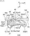
- the Figures 1 to 3 show a door 10 of a vehicle, which comprises a frame 11, a module 20 with an encapsulated fixed window, a movable window 14, a sliding joint 30, and hubcaps 40, 50.
- the door 10 is a vehicle front door.
- the frame 11 comprises a lower part 10a and an upper frame 12 defining an opening 13, this upper frame comprising two ascending uprights, respectively rear 12a and front 12b, connected by an upper rail 12c.
- the module 20 has a general shape in P and comprises a fixed window 22 mounted in a part, here before, of the opening 13, and an ascending profile 24 extending along a rising edge, here rear 22a, of the fixed window 22 and extending along the opening 13 and below a beltline line in the frame. It therefore extends at least partially in the lower part 20a of the frame 11.
- the fixed window 22 includes a front rising edge 22b extending along the rear upright 12b.
- the inner and outer surfaces of the window 22 are respectively designated by the references 22c and 22d.
- the movable window 14 is capable of closing the rest of the opening 13, behind the fixed window 22.
- the window 14 has two rising edges, respectively rear 14a and front 14b, along which guides 25, 26 are fixed.
- Each guide 25, 26 has an elongated shape and is fixed by any suitable technique and for example by bonding to an interior surface 14c of the window 14.
- the exterior surface of the window 14 is designated by the reference 14d.
- the sliding joint 30 has a general inverted U shape and comprises two ascending strands, respectively rear 30a and front 30b, connected by an upper strand 30c.
- the rear strand 30a extends along the rear upright 12a
- the front strand 30b extends along the profile 24.
- the upper strand 30c extends forward and is connected at its front end to an ascending strand 30d additional.
- the extension of the strand 30c extends along the upper edge 22e of the window 22 and of a part front of upper rail 12c.
- the additional strand 30d extends along the front edge 22b of the fixed window 22 and the front upright 12b.
- a first hubcap, rear 40, is attached to the rear strand 30a and fixed to the rear upright 12a.
- a second cover, before 50, is attached to the front strand 30b and fixed to the profile 24.
- the door 10 is of the “flush” type described in the above and the figures 6 , 5 and 4 respectively show sectional views along lines AA, BB and CC of the figure 1 .
- the figure 4 therefore shows a sectional view of the upper strand 30c and the upper rail 12c.
- the figure 5 shows a sectional view of the rear upright 12, the rear strand 30a and the rear hubcap 40, and the figure 6 shows a sectional view of the front strand 30b, the front trim 50 and the profile 24.
- the upper rail 12c comprises a folded sheet, an upper longitudinal edge 12c1 of which is engaged in a clip 32 with a U-section of the upper strand 30c.
- the upper edge 12c1 is oriented towards the outside and the clip 32 is mounted on this edge by translation from the outside to the inside, until the edge 12c1 is engaged at the bottom of the opening of the clip which is therefore oriented inward.
- the clip 32 comprises two side walls 32a, 32b, respectively lower and upper, connected together by an outer central wall 32c.
- the upper strand 30c comprises a portion 34 of U-shaped section, the opening of which is oriented downwards and is intended to receive the upper edge 14d of the movable window 14.
- the portion 34 comprises two walls lateral 34a, 34b, respectively inner and outer, and connected together by an upper middle wall 34c.
- the wall 34 comprises at its lower end a lug 36 for hooking onto a lower longitudinal edge 12c1 of the rail 12c.
- the clip 32 and the portion 34 are combined so as to limit their size, the walls 32a and 34c are here combined.
- the upper strand 30c comprises several sealing lips cooperating with the window 14, the rail 12c as well as the vehicle body.
- the guide 25 is fixed on the inner surface 14c of the window 14, along its rear rising edge 14a.
- the guide 25 has an elongated shape and extends along the axis X beyond the edge 14a to be engaged in a longitudinal groove 37 of the strand 30a.
- the guide 25 can also comprise at its rear end, opposite the window 14, at least one hook 28 for guiding and / or retaining which is oriented towards the outside.
- the rear strand 30a has in cross section a general C shape to define the groove 37 for receiving the guide 25.
- the strand 30a has two branches, respectively exterior 30a1 and interior 30a2, connected together by a middle branch 30a3.
- the outer branch 30a1 has a general S-shaped cross-section and comprises an upward groove 30a11 oriented inwards and intended to receive the hook (s) 28 of the guide 25, and an upward groove 30a12 oriented outwards and intended to receive an ascending rib 42 of the hubcap 40.
- the groove 30a11 is located between the middle branch 30a3 and the groove 30a12.
- the branch 30a comprises at its free end before an ascending sealing lip 30a13 occupying the space between the hubcap 40 and the edge 14a of the window 14, and bearing on this edge 14a.
- the strand 30 may include other sealing lips intended to cooperate with the window 14, the guide 25, the upright 12a, etc.
- the inner branch 30a2 bears inwardly on a front part 12a1 of the upright 12a, a rear part 12a2 of which extends outwards, behind the branch 30a3, to define with the latter an engagement space d 'a lug 44 of the hubcap 40.
- the inner branch 30a2 comprises at its front end a lug 30a21 for hooking on a front longitudinal edge of the part 12a1.
- the hubcap 40 comprises an ascending wall 46 parallel to the axis X and comprising an interior surface 40b and an exterior surface 40a which is aligned with the exterior surface 14d of the window pane 14.
- the rib 42 and the lug 44 project from the inner surface 40b of the wall. They are substantially parallel and the rib 42 is located in front of the tab 44, in the vicinity of the front rising edge of the wall.
- the rib 42 has a dimension along the axis Y which is less than that of the lug 44. This rib 42 is mounted fitted tightly in the groove 30a12 and makes it possible to precisely position and retain the strand 30a.
- the tab 44 is also fitted tightly between the rear part 12a2 and the branch 30a3.
- the guide 26 is fixed on the inner surface 14c of the window 14, along its front rising edge 14b.
- the guide 26 has an elongated shape and extends along the axis X beyond the edge 14b to be engaged in a longitudinal groove 37 of the strand 30b.
- the front strand 30b has a generally C-shaped section to define the groove 37 for receiving the guide 26.
- the strand 30b has two branches, respectively external 30b1 and internal 30b2, connected together by a middle branch 30b3.
- the external branch 30b1 comprises an ascending groove 30b12 oriented towards the outside and intended to receive a lug of an ascending rib 52 of the hubcap 50. Furthermore, the branch 30a has at its rear free end an ascending sealing lip 30b13 occupying the space between the hubcap 50 and the edge 14b of the window 14, and bearing on this edge 14b.
- the strand 30 may include other sealing lips intended to cooperate with the window 14, the guide 26 the upright 12b, etc.
- the inner branch 30b2 bears inwardly on a rear part 24a of the profile 24, a front part 24b of which is fixed to the fixed window 22.
- the profile 24 has a general L shape and includes the rear part 24a which is substantially parallel to the axis X and the front part 24a which extends outwards, parallel to the axis Y from the front end of part 24a.
- the profile 24 comprises a rigid plastic body 27a and an overmolded covering 27b which is configured to fix the plastic body to the fixed window 14.
- the body 27a comprises a base 27a1 for fixing to the internal surface 22c of the fixed window 22.
- the overmolded coating 27b comprises a first portion 27b1 interposed between the base 27a1 and the inner surface 22c of the fixed window 22, and a second portion 27b2 covering said rising edge 22a of the fixed window 22.
- the body 27a further comprises an ascending slot 29 for receiving a tab 54 of the hubcap 50.
- the slot 29 extends parallel to the axis Y and comprises a first side wall, here before 29a, substantially aligned with the edge 22a or portion 27b2.
- the slot 29 comprises a second side wall, here rear 29b, comprising orifices 31 for elastic snap-fastening of hooks 56 carried by the tab 54.
- the side wall 29b of the slot 29 is here carried by a wall with an L-shaped section of the body, a part 29b1 of this wall extending parallel to the axis Y and comprising the orifices 31, and a part 29b2 extending parallel to the X axis, from the outer end of bet 29b1 backwards.
- This part 29b2 comprises an ascending rib 29b3 oriented towards the rear and engaged in an ascending notch 58 of shape complementary to the rib 52 of the hubcap 50.
- the hubcap 50 comprises an ascending wall 56 parallel to the axis X and comprising an interior surface 50b and an exterior surface 50a which is aligned with the exterior surfaces 14d, 22d of the panes 14, 22.
- the rib 52 and the tab 54 are protruding on the inner surface 50b of the wall 56.
- the aforementioned lug protrudes inwards on the end inside of the rib 52, and the notch 58 is formed on a rear face of this rib 52.
- the hubcap 50 can be fixed on the profile 24 by an elastic double snap-fastening, that of the tab 54 in the slot 29 and that of the rib 52 at the level of the rib 29b3 and the groove 30b12.
- the figures 7 and 8 illustrate alternative embodiments of the strand 30b.
- the body 27a does not include a part 29b2.
- the outer branch 30b1 of the strand 30b has an S-shaped section and comprises an ascending groove 30b11 oriented inwards, and an ascending groove 30b12 oriented outwards and intended to receive the rib 52 of the hubcap 50.
- the groove 30b11 is located between the middle branch 30b3 and the groove 30b12.
- the rib 52 of the hubcap 50 does not have a lug or a groove 58.
- the variant of the figure 8 differs from that of the figure 7 in that the guide 26 comprises at least one hook 28 intended to be engaged in the groove 30b11 of the strand 30b in order to ensure correct positioning and retention of the window 14.
- the variant of the figure 9 differs from that of figures 7 and 8 in that the outer branch 30b1 of the strand 30b has neither a groove 30b11 nor a groove 30b12.
- This branch 30b1 is substantially flat and interposed between the guide 26 and the wall 56 of the hubcap 50.
- a window 14 when a window 14 is equipped with a guide 25 or 26 which includes a hook 28, the other guide 26 or 25 of this window does not include such a hook, this in order to facilitate assembly and sliding. of the window 14 in the door 10 and the sliding seal 30.
- the upper strand 30c of the sliding joint 30 is mounted on the upper rail 12c by a translation of this upper strand in a direction substantially perpendicular to a plane of the upper frame of the door frame and facing the inside of the door.
- This direction is schematically represented by two parallel arrows in the drawing.
- at least the second cover 50 is fixed by elastic snap-fastening to the rising profile 24.
Abstract
Description
- La présente invention concerne notamment une porte de véhicule du type « flush » ainsi qu'un procédé de montage de cette porte.
- Un véhicule comprend des portes qui comportent chacune en général au moins une vitre. Comme cela est visible à la
figure 1 , une porte 10 comprend une partie basse 10a et une partie haute 10b qui forme un cadre 12 destiné à entourer la vitre 14. Lorsque cette vitre 14 est mobile, elle peut être déplacée de la partie haute 10b dans la partie basse 10a. Le cadre 12 a une forme générale en U inversé et comprend deux montants ascendants 12a, 12b reliées par un rail supérieur 12c. - Dans la présente demande, on entend par « ascendant », un élément qui a une forme générale allongée et s'étend sensiblement du bas vers le haut, ou du haut vers le bas, par exemple verticalement.
- La plupart des portes, qui sont destinées à équiper des véhicules de gamme standard, sont du type « non flush », c'est-à-dire que leurs vitres n'ont pas leurs surfaces extérieures alignées avec des surfaces extérieures des éléments qui s'étendent au moins en partie autour des vitres, tels que des enjoliveurs par exemple.
- Dans la présente demande, on entend par « enjoliveur », tout élément de finition pour une porte de véhicule, et concerne notamment les appliqués, les profilés métalliques ou métallisés, etc.
- Pour une gamme plus luxueuse de véhicule, il est connu de les équiper de portes « flush ». Ce type de porte a sa vitre mobile dont la surface extérieure est alignée avec des surfaces extérieures d'éléments avoisinants. Cet alignement ou affleurement confère un aspect esthétique recherché par la clientèle.
- La présente invention propose un perfectionnement à une porte « flush » qui permet notamment de faciliter son montage et son rendu final.
- L'invention propose une porte de véhicule, comportant :
- un bâti comportant une partie basse et un cadre supérieur définissant une ouverture, ce cadre supérieur comportant deux montants ascendants reliés par un rail supérieur,
- un module à vitre fixe encapsulée, ce module ayant une forme générale en P et comportant une vitre fixe montée dans une partie de ladite ouverture, et un profilé ascendant s'étendant le long d'un bord ascendant de la vitre fixe et s'étendant depuis l'ouverture jusqu'à la partie basse du bâti,
- une vitre mobile apte à fermer le reste de ladite ouverture, cette vitre comportant deux bords ascendants le long desquels sont fixés des guides,
- un joint de coulisse ayant une forme générale en U et comportant deux brins ascendants reliés par un brin supérieur, les brins ascendants ayant en section transversale une forme générale en C et comportant chacun une gorge longitudinale de réception et de guidage d'un desdits guides, un premier des brins ascendants s'étendant le long d'un premier des montants ascendants, et un second des brins ascendants s'étendant le long dudit profilé ascendant,
- L'invention propose ainsi une porte conçue pour conférer un aspect « flush » entre les vitres fixe et mobile et entre ces vitres et des enjoliveurs de la porte.
- La porte selon l'invention peut comprendre une ou plusieurs des caractéristiques suivantes, prises isolément les unes des autres ou en combinaison les unes avec les autres :
- ledit profilé ascendant comprend un corps en plastique rigide et un revêtement surmoulé qui est configuré pour fixer le corps plastique à la vitre fixe,
- ledit corps comprend une embase de fixation à une surface intérieure de la vitre fixe, ledit revêtement surmoulé comportant une première portion intercalée entre l'embase et la surface intérieure de la vitre fixe, et une seconde portion recouvrant ledit bord ascendant de la vitre fixe,
- ledit corps comprend une fente ascendante de réception d'une patte dudit second enjoliveur,
- ladite fente comprend s'étend dans un plan sensiblement perpendiculaire à ladite vitre fixe et comprend une première paroi latérale sensiblement alignée avec ledit bord ascendant ou une portion dudit revêtement surmoulé,
- ladite fente comprend une seconde paroi latérale comportant des orifices d'encliquetage élastique de crochets portés par ladite patte,
- ledit second enjoliveur a en section une forme générale en L,
- le second enjoliveur comprend une paroi s'étendant parallèlement aux vitres fixe et mobile, et entre celles-ci, cette paroi comportant ladite surface extérieure du second enjoliveur,
- la paroi dudit second enjoliveur comporte en outre une surface intérieure sur laquelle est située en saillie ou en retrait une nervure ascendante sensiblement parallèle audit bord ascendant,
- lesdits brins ascendants comportent chacun une branche extérieure, une branche intérieure et une branche médiane de liaison des branches intérieure et extérieure,
- la branche extérieure de l'un au moins desdits brins ascendants comporte une première rainure ascendante orientée vers l'extérieur et dans lequel est au moins en partie engagée une nervure ascendante dudit enjoliveur correspondant,
- la branche extérieure de l'un au moins desdits brins ascendants comporte une seconde rainure ascendante orientée vers l'intérieur et dans lequel peut être au moins en partie engagé au moins un crochet d'un desdits guides.
- ledit brin supérieur comprend une agrafe en U de fixation sur ledit rail supérieur,
- ledit brin supérieur comprend un prolongement qui s'étend autour d'une partie de la vitre fixe et le long d'un desdits montants ascendants,
- au moins un desdits premier et second enjoliveurs est réalisé d'une seule pièce à partir de deux matériaux,
- le joint de coulisse est monobloc.
- La présente invention concerne encore un véhicule, comportant au moins une porte telle que décrite ci-dessus.
- La présente invention concerne également un procédé de montage d'une porte telle que décrite ci-dessus, dans lequel il comprend les étapes de :
- montage du module à vitre fixe encapsulée sur le bâti,
- montage du joint de coulisse,
- montage de la vitre mobile, et
- montage des premier et second enjoliveurs.
- De préférence, lors de l'étape b), le brin supérieur du joint de coulisse est monté sur ledit rail supérieur par une translation de ce brin supérieur dans une direction sensiblement perpendiculaire à un plan du cadre supérieur du bâti de porte et orientée vers l'intérieur de la porte.
- Avantageusement, le second enjoliveur est fixé par encliquetage élastique sur ledit profilé ascendant.
- L'invention sera mieux comprise et d'autres détails, caractéristiques et avantages de l'invention apparaîtront plus clairement à la lecture de la description suivante faite à titre d'exemple non limitatif et en référence aux dessins annexés dans lesquels :
- la
figure 1 est une vue schématique en perspective d'une porte de véhicule, - la
figure 2 est une vue schématique en perspective éclatée de la porte de lafigure 1 , - la
figure 3 est une vue schématique en perspective de certains éléments de la porte de lafigure 1 , - la
figure 4 est une vue schématique en coupe selon la ligne C-C de lafigure 1 , - la
figure 5 est une vue schématique en coupe selon la ligne B-B de lafigure 1 , - la
figure 6 est une vue schématique en coupe selon la ligne A-A de lafigure 1 , et - la
figure 7 est une vue similaire à celle de lafigure 6 et montre une variante de réalisation, - la
figure 8 est une vue similaire à celle de lafigure 6 et montre une variante de réalisation, et - la
figure 9 est une vue similaire à celle de lafigure 6 et montre une variante de réalisation. - Dans la description qui suit et en référence aux dessins, on utilise un repère tridimensionnel dont l'axe X est horizontal et orienté dans la direction de déplacement du véhicule, l'axe Y est horizontal et orienté vers l'intérieur du véhicule, et l'axe Z est vertical et orienté vers le haut. Les termes « avant » et « arrière » font référence à l'avant et à l'arrière du véhicule par rapport à l'axe X. Les termes « intérieur » et « extérieur » font référence à l'intérieur et à l'extérieur du véhicule par rapport à l'axe Y. Enfin, les termes « inférieur » ou « bas/basse » et « extérieur » ou « haut/haute » font référence au bas ou au haut du véhicule par rapport à l'axe Z.
- Les
figures 1 à 3 montrent une porte 10 d'un véhicule, qui comporte un bâti 11, un module 20 à vitre fixe encapsulée, une vitre mobile 14, un joint de coulisse 30, et des enjoliveurs 40, 50. Dans l'exemple représenté, la porte 10 est une porte avant de véhicule. - Le bâti 11 comporte une partie basse 10a et un cadre supérieur 12 définissant une ouverture 13, ce cadre supérieur comportant deux montants ascendants, respectivement arrière 12a et avant 12b, reliés par un rail supérieur 12c.
- Le module 20 a une forme générale en P et comporte une vitre fixe 22 montée dans une partie, ici avant, de l'ouverture 13, et un profilé ascendant 24 s'étendant le long d'un bord ascendant, ici arrière 22a, de la vitre fixe 22 et s'étendant le long de l'ouverture 13 et en deçà d'une ligne ceinture de caisse dans le bâti. Elle s'étend donc au moins en partie dans la partie basse 20a du bâti 11. La vitre fixe 22 comprend un bord ascendant avant 22b s'étendant le long du montant arrière 12b. Les surfaces intérieure et extérieure de la vitre 22 sont respectivement désignées par les références 22c et 22d.
- La vitre mobile 14 est apte à fermer le reste de l'ouverture 13, en arrière de la vitre fixe 22. La vitre 14 comporte deux bords ascendants, respectivement arrière 14a et avant 14b, le long desquels sont fixés des guides 25, 26. Chaque guide 25, 26 a une forme allongée et est fixé par toute technique appropriée et par exemple par collage sur une surface intérieure 14c de la vitre 14. La surface extérieure de la vitre 14 est désignée par la référence 14d.
- Le joint de coulisse 30 a une forme générale en U inversé et comporte deux brins ascendants, respectivement arrière 30a et avant 30b, reliés par un brin supérieur 30c. Le brin arrière 30a s'étend le long du montant arrière 12a, et le brin avant 30b s'étend le long du profilé 24. Le brin supérieur 30c se prolonge vers l'avant et est reliée à son extrémité avant à un brin ascendant 30d supplémentaire. Le prolongement du brin 30c s'étend le long du bord supérieur 22e de la vitre 22 et d'une partie avant du rail supérieur 12c. Le brin supplémentaire 30d s'étend le long du bord avant 22b de la vitre fixe 22 et du montant avant 12b.
- Un premier enjoliveur, arrière 40, est rapporté sur le brin arrière 30a et fixé sur le montant arrière 12a. Un second enjoliveur, avant 50, est rapporté sur le brin avant 30b et fixé sur le profilé 24.
- La porte 10 est du type « flush » décrit dans ce qui précède et les
figures 6 ,5 et4 montrent respectivement des vues en coupe selon les lignes A-A, B-B et C-C de lafigure 1 . Lafigure 4 montre donc une vue en coupe du brin supérieur 30c et du rail supérieur 12c. Lafigure 5 montre une vue en coupe du montant arrière 12, du brin arrière 30a et de l'enjoliveur arrière 40, et lafigure 6 montre une vue en coupe du brin avant 30b, de l'enjoliveur avant 50 et du profilé 24. - En référence à la
figure 4 , on constate que le rail supérieur 12c comprend une tôle pliée dont un bord longitudinal supérieur 12c1 est engagé dans une agrafe 32 à section en U du brin supérieur 30c. Le bord supérieur 12c1 est orienté vers l'extérieur et l'agrafe 32 est montée sur ce bord par translation de l'extérieur vers l'intérieur, jusqu'à ce que le bord 12c1 soit engagé au fond de l'ouverture de l'agrafe qui est donc orientée vers l'intérieur. L'agrafe 32 comprend deux parois latérales 32a, 32b, respectivement inférieure et supérieure, reliées entre elles par une paroi médiane extérieure 32c. - En plus de l'agrafe 32, le brin supérieur 30c comprend une portion 34 à section en U dont l'ouverture est orientée vers le bas et est destinée à recevoir le bord supérieur 14d de la vitre mobile 14. La portion 34 comprend deux parois latérales 34a, 34b, respectivement intérieure et extérieure, et reliées entre elles par une paroi médiane supérieure 34c. La paroi 34 comprend à son extrémité inférieure une patte 36 d'accrochage sur un bord longitudinal inférieur 12c1 du rail 12c.
- Dans l'exemple représenté, l'agrafe 32 et la portion 34 sont combinées de sorte à limiter leur encombrement, les parois 32a et 34c sont ici confondues.
- Le brin supérieur 30c comprend plusieurs lèvres d'étanchéité coopérant avec la vitre 14, le rail 12c ainsi que la carrosserie du véhicule.
- En référence à la
figure 5 , le guide 25 est fixé sur la surface intérieure 14c de la vitre 14, le long de son bord ascendant arrière 14a. Le guide 25 a une forme allongée et s'étend le long de l'axe X au-delà du bord 14a pour être engagé dans une gorge longitudinale 37 du brin 30a. Le guide 25 peut en outre comprendre à son extrémité arrière, opposée à la vitre 14, au moins un crochet 28 de guidage et/ou de retenue qui est orienté vers l'extérieur. - Le brin arrière 30a a en section une forme générale en C pour définir la gorge 37 de réception du guide 25. Le brin 30a comporte deux branches, respectivement extérieure 30a1 et intérieure 30a2, reliées ensemble par une branche médiane 30a3.
- La branche extérieure 30a1 a en section une forme générale en S et comprend une rainure ascendante 30a11 orientée vers l'intérieur et destinée à recevoir le ou les crochet(s) 28 du guide 25, et une rainure ascendante 30a12 orientée vers l'extérieur et destinée à recevoir une nervure ascendante 42 de l'enjoliveur 40. La rainure 30a11 est située entre la branche médiane 30a3 et la rainure 30a12. Par ailleurs, la branche 30a comporte à son extrémité libre avant une lèvre ascendante d'étanchéité 30a13 occupant l'espace entre l'enjoliveur 40 et le bord 14a de la vitre 14, et prenant appui sur ce bord 14a. Le brin 30 peut comprendre d'autres lèvres d'étanchéité destinées à coopérer avec la vitre 14, le guide 25, le montant 12a, etc.
- La branche intérieure 30a2 est en appui vers l'intérieur sur une partie avant 12a1 du montant 12a dont une partie arrière 12a2 s'étend vers l'extérieur, en arrière de la branche 30a3, pour définir avec cette dernière un espace d'engagement d'une patte 44 de l'enjoliveur 40.
- La branche intérieure 30a2 comprend à son extrémité avant une patte 30a21 d'accrochage sur un bord longitudinal avant de la partie 12a1.
- L'enjoliveur 40 comprend une paroi ascendante 46 parallèle à l'axe X et comportant une surface intérieure 40b et une surface extérieure 40a qui est alignée avec la surface extérieure 14d de la vitre 14.
- La nervure 42 et la patte 44, décrites dans ce qui précède, sont en saillie sur la surface intérieure 40b de la paroi. Elles sont sensiblement parallèles et la nervure 42 est située en avant de la patte 44, au voisinage du bord ascendant avant de la paroi. La nervure 42 a une dimension le long de l'axe Y qui est inférieure à celle de la patte 44. Cette nervure 42 est montée ajustée serrée dans la rainure 30a12 et permet de positionner avec précision et retenir le brin 30a. La patte 44 est également ajustée serrée entre la partie arrière 12a2 et la branche 30a3.
- En référence à la
figure 6 , le guide 26 est fixé sur la surface intérieure 14c de la vitre 14, le long de son bord ascendant avant 14b. Le guide 26 a une forme allongée et s'étend le long de l'axe X au-delà du bord 14b pour être engagé dans une gorge longitudinale 37 du brin 30b. - Le brin avant 30b a en section une forme générale en C pour définir la gorge 37 de réception du guide 26. Le brin 30b comporte deux branches, respectivement extérieure 30b1 et intérieure 30b2, reliées ensemble par une branche médiane 30b3.
- La branche extérieure 30b1 comprend une rainure ascendante 30b12 orientée vers l'extérieur et destinée à recevoir un ergot d'une nervure ascendante 52 de l'enjoliveur 50. Par ailleurs, la branche 30a comporte à son extrémité libre arrière une lèvre ascendante d'étanchéité 30b13 occupant l'espace entre l'enjoliveur 50 et le bord 14b de la vitre 14, et prenant appui sur ce bord 14b. Le brin 30 peut comprendre d'autres lèvres d'étanchéité destinées à coopérer avec la vitre 14, le guide 26 le montant 12b, etc.
- La branche intérieure 30b2 est en appui vers l'intérieur sur une partie arrière 24a du profilé 24 dont une partie avant 24b est fixée à la vitre fixe 22.
- Le profilé 24 a une forme générale en L et comprend la partie arrière 24a qui est sensiblement parallèle à l'axe X et la partie avant 24a qui s'étend vers l'extérieur, parallèlement à l'axe Y depuis l'extrémité avant de la partie 24a.
- Le profilé 24 comprend un corps 27a en plastique rigide et un revêtement surmoulé 27b qui est configuré pour fixer le corps plastique à la vitre fixe 14. Le corps 27a comprend une embase 27a1 de fixation à la surface intérieure 22c de la vitre fixe 22. Le revêtement surmoulé 27b comporte une première portion 27b1 intercalée entre l'embase 27a1 et la surface intérieure 22c de la vitre fixe 22, et une seconde portion 27b2 recouvrant ledit bord ascendant 22a de la vitre fixe 22.
- Le corps 27a comprend en outre une fente ascendante 29 de réception d'une patte 54 de l'enjoliveur 50. La fente 29 s'étend parallèlement à l'axe Y et comprend une première paroi latérale, ici avant 29a, sensiblement alignée avec le bord 22a ou la portion 27b2.
- La fente 29 comprend une seconde paroi latérale, ici arrière 29b, comportant des orifices 31 d'encliquetage élastique de crochets 56 portés par la patte 54.
- La paroi latérale 29b de la fente 29 est ici portée par une paroi à section en L du corps, une partie 29b1 de cette paroi s'étendant parallèlement à l'axe Y et comprenant les orifices 31, et une partie 29b2 s'étendant parallèlement à l'axe X, depuis l'extrémité extérieure de la parie 29b1 vers l'arrière. Cette partie 29b2 comprend une nervure ascendante 29b3 orientée vers l'arrière et engagée dans une encoche ascendante 58 de forme complémentaire de la nervure 52 de l'enjoliveur 50.
- L'enjoliveur 50 comprend une paroi ascendante 56 parallèle à l'axe X et comportant une surface intérieure 50b et une surface extérieure 50a qui est alignée avec les surfaces extérieures 14d, 22d des vitres 14, 22. La nervure 52 et la patte 54 sont en saillie sur la surface intérieure 50b de la paroi 56. L'ergot précité est en saillie vers l'intérieur sur l'extrémité intérieure de la nervure 52, et l'encoche 58 est formée sur une face arrière de cette nervure 52.
- On comprend que l'enjoliveur 50 peut être fixé sur le profilé 24 par un double encliquetage élastique, celui de la patte 54 dans la fente 29 et celui de la nervure 52 au niveau de la nervure 29b3 et de la rainure 30b12.
- Les
figures 7 et8 illustrent des variantes de réalisation du brin 30b. - Dans la variante de la
figure 7 , le corps 27a ne comprend pas de partie 29b2. La branche extérieure 30b1 du brin 30b a en section une forme en S et comprend une rainure ascendante 30b11 orientée vers l'intérieur, et une rainure ascendante 30b12 orientée vers l'extérieur et destinée à recevoir la nervure 52 de l'enjoliveur 50. La rainure 30b11 est située entre la branche médiane 30b3 et la rainure 30b12. La nervure 52 de l'enjoliveur 50 ne comporte pas d'ergot ni de rainure 58. - La variante de réalisation de la
figure 8 diffère de celle de lafigure 7 en ce que le guide 26 comprend au moins un crochet 28 destiné à être engagé dans la rainure 30b11 du brin 30b en vue d'assurer un positionnement correct et une rétention de la vitre 14. - La variante de réalisation de la
figure 9 diffère de celle desfigures 7 et8 en ce que la branche extérieure 30b1 du brin 30b ne comporte ni de rainure 30b11 ni de rainure 30b12. Cette branche 30b1 est sensiblement plane et intercalée entre le guide 26 et la paroi 56 de l'enjoliveur 50. - De manière préférée, lorsqu'une vitre 14 est équipée d'un guide 25 ou 26 qui comprend un crochet 28, l'autre guide 26 ou 25 de cette vitre ne comprend pas un tel crochet, ceci afin de faciliter le montage et le coulissement de la vitre 14 dans la porte 10 et le joint de coulisse 30.
- L'invention concerne en outre un procédé de montage de la porte 10, qui comprend (en référence à la
figure 2 par exemple) les étapes de : - a) montage du module à vitre fixe encapsulée 20 sur le bâti 11,
- b) montage du joint de coulisse 30,
- c) montage de la vitre mobile 14, et
- d) montage des enjoliveurs 40, 50.
- De préférence, lors de l'étape b), le brin supérieur 30c du joint de coulisse 30 est monté sur le rail supérieur 12c par une translation de ce brin supérieur dans une direction sensiblement perpendiculaire à un plan du cadre supérieur du bâti de porte et orientée vers l'intérieur de la porte. Cette direction est schématiquement représentée par deux flèches parallèles dans le dessin. Avantageusement, au moins le second enjoliveur 50 est fixé par encliquetage élastique sur le profilé ascendant 24.
Claims (15)
- Porte (10) de véhicule, comportant :- un bâti (11) comportant une partie basse (10a) et un cadre supérieur (12) définissant une ouverture (13), ce cadre supérieur comportant deux montants ascendants (12a, 12b) reliés par un rail supérieur (12c),- un module (20) à vitre fixe encapsulée, ce module ayant une forme générale en P et comportant une vitre fixe (22) montée dans une partie de ladite ouverture, et un profilé ascendant (24) s'étendant le long d'un bord ascendant (22a) de la vitre fixe et s'étendant depuis l'ouverture jusqu'à la partie basse du bâti,- une vitre mobile (14) apte à fermer le reste de ladite ouverture, cette vitre comportant deux bords ascendants (14a, 14b) le long desquels sont fixés des guides (25, 26),- un joint de coulisse (30) ayant une forme générale en U et comportant deux brins ascendants (30a, 30b) reliés par un brin supérieur (30c), les brins ascendants ayant en section transversale une forme générale en C et comportant chacun une gorge longitudinale (37) de réception et de guidage d'un desdits guides, un premier (30a) des brins ascendants s'étendant le long d'un premier (12a) des montants ascendants, et un second (30b) des brins ascendants s'étendant le long dudit profilé ascendant (24),les vitres fixe et mobile comportant des surfaces extérieures (14d, 22d) qui sont alignées entre elles ainsi qu'avec une surface extérieure (40a) d'un premier enjoliveur (40) rapporté sur le premier brin ascendant (30a) et fixé sur ledit premier montant ascendant (12a), et une surface extérieure (50a) d'un second enjoliveur (50) rapporté sur le second brin ascendant (30b) et fixé sur ledit profilé ascendant (24).
- Porte (10) de véhicule selon la revendication 1, dans lequel ledit profilé ascendant (24) comprend un corps (27a) en plastique rigide et un revêtement surmoulé (27b) qui est configuré pour fixer le corps plastique à la vitre fixe (22).
- Porte (10) de véhicule selon la revendication 2, dans lequel ledit corps (27a) comprend une embase de fixation à une surface intérieure (22c) de la vitre fixe (22), ledit revêtement surmoulé (27b) comportant une première portion (27b1) intercalée entre l'embase et la surface intérieure de la vitre fixe, et une seconde portion (27b2) recouvrant ledit bord ascendant (22a) de la vitre fixe.
- Porte (10) de véhicule selon la revendication 2 ou 3, dans lequel ledit corps (27a) comprend une fente ascendante (29) de réception d'une patte (54) dudit second enjoliveur (50).
- Porte (10) de véhicule selon la revendication 4, dans lequel ladite fente (29) s'étend dans un plan sensiblement perpendiculaire à ladite vitre fixe (22) et comprend une première paroi latérale (29a) sensiblement alignée avec ledit bord ascendant (14a) ou une portion (27b2) dudit revêtement surmoulé (27b).
- Porte (10) de véhicule selon la revendication 5, dans lequel ladite fente (29) comprend une seconde paroi latérale (29b) comportant des orifices (31) d'encliquetage élastique de crochets (56) portés par ladite patte (54).
- Porte (10) de véhicule selon l'une des revendications précédentes, dans lequel ledit second enjoliveur (50) comprend une paroi (56) s'étendant parallèlement aux vitres fixe (22) et mobile (14), et entre celles-ci, cette paroi comportant ladite surface extérieure (50a) du second enjoliveur.
- Porte (10) de véhicule selon la revendication précédente, dans lequel la paroi (56) dudit second enjoliveur (50) comprend en outre une surface intérieure (50b) sur laquelle est située en saillie ou en retrait une nervure ascendante (52) sensiblement parallèle audit bord ascendant (22a).
- Porte (10) de véhicule selon l'une des revendications précédentes, dans lequel lesdits brins ascendants (30a, 30b) comportent chacun une branche extérieure (30a1, 30b1), une branche intérieure (30a2, 30b2) et une branche médiane (30a3, 30b3) de liaison des branches intérieure et extérieure.
- Porte (10) de véhicule selon la revendication 9, dans lequel la branche extérieure de l'un au moins desdits brins ascendants comporte une première rainure ascendante (30a12, 30b12) orientée vers l'extérieur et dans lequel est au moins en partie engagée une nervure ascendante (42, 52) dudit enjoliveur (40, 50) correspondant.
- Porte (10) de véhicule selon la revendication 9 ou 10, dans lequel la branche extérieure (30a1, 30b1) de l'un au moins desdits brins ascendants (30a, 30b) comporte une seconde rainure ascendante (30a11, 30b11) orientée vers l'intérieur et dans lequel peut être au moins en partie engagé au moins un crochet (28) d'un desdits guides (25, 26).
- Porte (10) de véhicule selon l'une des revendications précédentes, dans lequel ledit brin supérieur (30c) comprend un prolongement qui s'étend autour d'une partie de la vitre fixe (22) et le long d'un desdits montants ascendants (12b).
- Véhicule, comportant au moins une porte (10) selon l'une des revendications précédentes.
- Procédé de montage d'une porte (10) selon l'une des revendications 1 à 12, dans lequel il comprend les étapes de :a) montage du module (20) à vitre fixe encapsulée sur le bâti (11),b) montage du joint de coulisse (30),c) montage de la vitre mobile (14), etd) montage des premier et second enjoliveurs (40, 50).
- Procédé selon la revendication précédente, dans lequel, lors de l'étape b), le brin supérieur (30c) du joint de coulisse (30) est monté sur ledit rail supérieur (12c) par une translation de ce brin supérieur dans une direction sensiblement perpendiculaire à un plan du cadre supérieur (12) du bâti (12) de porte et orientée vers l'intérieur de la porte.
Priority Applications (1)
| Application Number | Priority Date | Filing Date | Title |
|---|---|---|---|
| HRP20230728TT HRP20230728T1 (hr) | 2018-12-10 | 2019-12-10 | Vrata vozila tipa u ravnini |
Applications Claiming Priority (1)
| Application Number | Priority Date | Filing Date | Title |
|---|---|---|---|
| FR1872637A FR3089461B1 (fr) | 2018-12-10 | 2018-12-10 | Porte de véhicule du type “flush” |
Publications (2)
| Publication Number | Publication Date |
|---|---|
| EP3666569A1 true EP3666569A1 (fr) | 2020-06-17 |
| EP3666569B1 EP3666569B1 (fr) | 2023-05-10 |
Family
ID=66286469
Family Applications (1)
| Application Number | Title | Priority Date | Filing Date |
|---|---|---|---|
| EP19214633.0A Active EP3666569B1 (fr) | 2018-12-10 | 2019-12-10 | Porte de véhicule du type flush |
Country Status (7)
| Country | Link |
|---|---|
| US (1) | US11639086B2 (fr) |
| EP (1) | EP3666569B1 (fr) |
| CN (1) | CN111284310A (fr) |
| ES (1) | ES2950090T3 (fr) |
| FR (1) | FR3089461B1 (fr) |
| HR (1) | HRP20230728T1 (fr) |
| PL (1) | PL3666569T3 (fr) |
Families Citing this family (8)
| Publication number | Priority date | Publication date | Assignee | Title |
|---|---|---|---|---|
| DE102017112720A1 (de) * | 2017-06-09 | 2018-12-13 | Cqlt Saargummi Technologies S.À.R.L. | Dichtungsanordnung |
| FR3076770B1 (fr) * | 2018-01-18 | 2020-01-24 | Cooper Standard France | Dispositif de guidage d'une vitre coulissante, porte vitree de vehicule equipee de ce dispositif et vehicule equipe d'une telle porte |
| FR3089459B1 (fr) * | 2018-12-10 | 2020-11-13 | Hutchinson | Kit et procédé d’habillage d’un rail de porte d’un véhicule |
| US11052731B2 (en) * | 2019-02-05 | 2021-07-06 | Volvo Car Corporation | Vehicle flush window system, a vehicle comprising same, and related assembly method |
| KR20200106396A (ko) * | 2019-03-04 | 2020-09-14 | 현대자동차주식회사 | 임팩트빔의 벤딩 구조 및 벤딩 장치 |
| FR3097169B1 (fr) * | 2019-06-17 | 2021-05-28 | Hutchinson | Module de vitres affleurant pour un vehicule et son procede de montage |
| EP4005837B1 (fr) * | 2020-11-25 | 2024-03-27 | HUTCHINSON GmbH | Guide pour un vitrage coulissant |
| EP4292845A1 (fr) * | 2022-06-13 | 2023-12-20 | Cooper Standard GmbH | Brin de profilé d'étanchéité et agencement d'étanchéité pour une fenêtre coulissante |
Citations (5)
| Publication number | Priority date | Publication date | Assignee | Title |
|---|---|---|---|---|
| US4653230A (en) * | 1985-03-13 | 1987-03-31 | Toyota Jidosha Kabushiki Kaisha | Vehicle body structure |
| US5199761A (en) * | 1991-03-02 | 1993-04-06 | Mercedes-Benz Ag | Side window for a motor vehicle |
| FR2858950A1 (fr) * | 2003-08-21 | 2005-02-25 | Hutchinson | Module d'etancheite d'une vitre fixe destine a etre monte sur une porte d'un vehicule |
| US20160121701A1 (en) * | 2013-05-31 | 2016-05-05 | Toyota Jidosha Kabushiki Kaisha | Window panel support structure |
| CA2983661A1 (fr) * | 2015-04-28 | 2016-11-03 | Hutchinson | Joint de coulisse pour vitrage de vehicule et module d'etancheite incorporant des moyens de guidage du vitrage dans le joint et un element du cadre de porte |
Family Cites Families (4)
| Publication number | Priority date | Publication date | Assignee | Title |
|---|---|---|---|---|
| US20110109009A1 (en) * | 2007-03-26 | 2011-05-12 | Hutchinson Sealing Systems, Inc. | Method of forming unsupported division post for automotive glass encapsulation |
| DE102016200475B3 (de) * | 2016-01-15 | 2016-12-15 | Brose Fahrzeugteile Gmbh & Co. Kommanditgesellschaft, Bamberg | Fahrzeugtürbaugruppe mit Einführbereichen an rahmenseitigen Führungselementen für ein flächenbündiges Scheibenkonzept und Montageverfahren |
| GB2557665B (en) * | 2016-12-15 | 2020-11-18 | Jaguar Land Rover Ltd | An elongate seal for providing a seal along a movable windowpane for a vehicle |
| DE102017004131A1 (de) | 2017-04-21 | 2018-10-25 | GM Global Technology Operations LLC (n. d. Ges. d. Staates Delaware) | Geteiltes Fenster und Mittelsteg dafür |
-
2018
- 2018-12-10 FR FR1872637A patent/FR3089461B1/fr active Active
-
2019
- 2019-12-09 US US16/708,071 patent/US11639086B2/en active Active
- 2019-12-10 PL PL19214633.0T patent/PL3666569T3/pl unknown
- 2019-12-10 CN CN201911256801.3A patent/CN111284310A/zh active Pending
- 2019-12-10 HR HRP20230728TT patent/HRP20230728T1/hr unknown
- 2019-12-10 ES ES19214633T patent/ES2950090T3/es active Active
- 2019-12-10 EP EP19214633.0A patent/EP3666569B1/fr active Active
Patent Citations (5)
| Publication number | Priority date | Publication date | Assignee | Title |
|---|---|---|---|---|
| US4653230A (en) * | 1985-03-13 | 1987-03-31 | Toyota Jidosha Kabushiki Kaisha | Vehicle body structure |
| US5199761A (en) * | 1991-03-02 | 1993-04-06 | Mercedes-Benz Ag | Side window for a motor vehicle |
| FR2858950A1 (fr) * | 2003-08-21 | 2005-02-25 | Hutchinson | Module d'etancheite d'une vitre fixe destine a etre monte sur une porte d'un vehicule |
| US20160121701A1 (en) * | 2013-05-31 | 2016-05-05 | Toyota Jidosha Kabushiki Kaisha | Window panel support structure |
| CA2983661A1 (fr) * | 2015-04-28 | 2016-11-03 | Hutchinson | Joint de coulisse pour vitrage de vehicule et module d'etancheite incorporant des moyens de guidage du vitrage dans le joint et un element du cadre de porte |
Also Published As
| Publication number | Publication date |
|---|---|
| PL3666569T3 (pl) | 2023-08-21 |
| FR3089461A1 (fr) | 2020-06-12 |
| US20200180405A1 (en) | 2020-06-11 |
| ES2950090T3 (es) | 2023-10-05 |
| US11639086B2 (en) | 2023-05-02 |
| HRP20230728T1 (hr) | 2023-10-13 |
| FR3089461B1 (fr) | 2020-11-13 |
| CN111284310A (zh) | 2020-06-16 |
| EP3666569B1 (fr) | 2023-05-10 |
Similar Documents
| Publication | Publication Date | Title |
|---|---|---|
| EP3666569B1 (fr) | Porte de véhicule du type flush | |
| EP3983248B1 (fr) | Module de vitres affleurant pour un vehicule et son procede de montage | |
| EP3356170A1 (fr) | Dispositif vitré affleurant pour porte de véhicule, porte, véhicule automobile, procédé de fabrication et dispositif d'étanchéité correspondants | |
| EP3681746B1 (fr) | Profilé lécheur de vitre avec montage facilité | |
| EP3582986B1 (fr) | Dispositif vitre affleurant pour porte de vehicule, porte, vehicule automobile, procede de fabrication et dispositif d'etancheite monobloc correspondants | |
| EP3647093B1 (fr) | Dispositif vitré d'un véhicule avec patin de guidage démontable, porte, véhicule et procédé de montage correspondants | |
| EP3666568B1 (fr) | Kit et procédé d'habillage d'un rail de porte d'un véhicule | |
| EP2155525B1 (fr) | Balai d'essuie-glace comportant une vertebre interne realisant le blocage d'un element de liaison sur la monture de support | |
| EP1022172B1 (fr) | Procédé de fabrication d'une portière pour véhicule automobile, et portière correspondante | |
| EP3678900B1 (fr) | Insert pour une coulisse de vitrage de véhicule | |
| EP2563609B1 (fr) | Ensemble comprenant un lecheur exterieur de vitre et un enjoliveur pourvus de moyens d'indexation et vehicule automobile equipe de tels ensembles | |
| WO2009092943A2 (fr) | Dispositif d'ameublement et procédé de fabrication d'un tel dispositif | |
| FR2929205A1 (fr) | Ensemble de pare-chocs de vehicule automobile. | |
| EP1657093B1 (fr) | Porte vitrée pour un véhicule comportant un guide de vitre muni d'un élément s'opposant au vrillage | |
| FR2944484A1 (fr) | Support de retroviseur et vehicule equipe d'un tel support | |
| EP1120302A1 (fr) | Ensemble de cadre pour vitre(s) ou glace(s) fixe et/ou mobile | |
| EP1982859B1 (fr) | Module d'étanchéité pour baie de véhicule à moteur, et une telle baie l'incorporant | |
| WO2020229649A1 (fr) | Lécheur extérieur avec enjoliveur évolutif | |
| FR2950854A1 (fr) | Partie avant de vehicule dotee d'une piece de fermeture de montant de baie multifonction. | |
| EP4164905A1 (fr) | Enjoliveur de porte de véhicule automobile | |
| FR3117989A1 (fr) | Enjoliveur extérieur pour ouvrant. | |
| FR3092526A1 (fr) | Capot d’étanchéité pour un module de vitre fixe d’un véhicule | |
| FR2801251A1 (fr) | Systeme d'ouvrant lateral coulissant pour un vehicule automobile | |
| EP4359262A1 (fr) | Procédé de transformation d'une première version d'un véhicule en une deuxième version | |
| EP3549803A1 (fr) | Assemblage par glissement d'une vitre et d'un hayon de véhicule automobile |
Legal Events
| Date | Code | Title | Description |
|---|---|---|---|
| PUAI | Public reference made under article 153(3) epc to a published international application that has entered the european phase |
Free format text: ORIGINAL CODE: 0009012 |
|
| STAA | Information on the status of an ep patent application or granted ep patent |
Free format text: STATUS: THE APPLICATION HAS BEEN PUBLISHED |
|
| AK | Designated contracting states |
Kind code of ref document: A1 Designated state(s): AL AT BE BG CH CY CZ DE DK EE ES FI FR GB GR HR HU IE IS IT LI LT LU LV MC MK MT NL NO PL PT RO RS SE SI SK SM TR |
|
| AX | Request for extension of the european patent |
Extension state: BA ME |
|
| STAA | Information on the status of an ep patent application or granted ep patent |
Free format text: STATUS: REQUEST FOR EXAMINATION WAS MADE |
|
| 17P | Request for examination filed |
Effective date: 20201007 |
|
| RBV | Designated contracting states (corrected) |
Designated state(s): AL AT BE BG CH CY CZ DE DK EE ES FI FR GB GR HR HU IE IS IT LI LT LU LV MC MK MT NL NO PL PT RO RS SE SI SK SM TR |
|
| STAA | Information on the status of an ep patent application or granted ep patent |
Free format text: STATUS: EXAMINATION IS IN PROGRESS |
|
| 17Q | First examination report despatched |
Effective date: 20210209 |
|
| GRAP | Despatch of communication of intention to grant a patent |
Free format text: ORIGINAL CODE: EPIDOSNIGR1 |
|
| STAA | Information on the status of an ep patent application or granted ep patent |
Free format text: STATUS: GRANT OF PATENT IS INTENDED |
|
| INTG | Intention to grant announced |
Effective date: 20221208 |
|
| GRAS | Grant fee paid |
Free format text: ORIGINAL CODE: EPIDOSNIGR3 |
|
| GRAA | (expected) grant |
Free format text: ORIGINAL CODE: 0009210 |
|
| STAA | Information on the status of an ep patent application or granted ep patent |
Free format text: STATUS: THE PATENT HAS BEEN GRANTED |
|
| AK | Designated contracting states |
Kind code of ref document: B1 Designated state(s): AL AT BE BG CH CY CZ DE DK EE ES FI FR GB GR HR HU IE IS IT LI LT LU LV MC MK MT NL NO PL PT RO RS SE SI SK SM TR |
|
| REG | Reference to a national code |
Ref country code: GB Ref legal event code: FG4D Free format text: NOT ENGLISH |
|
| REG | Reference to a national code |
Ref country code: AT Ref legal event code: REF Ref document number: 1566361 Country of ref document: AT Kind code of ref document: T Effective date: 20230515 Ref country code: CH Ref legal event code: EP |
|
| REG | Reference to a national code |
Ref country code: DE Ref legal event code: R096 Ref document number: 602019028686 Country of ref document: DE |
|
| REG | Reference to a national code |
Ref country code: IE Ref legal event code: FG4D Free format text: LANGUAGE OF EP DOCUMENT: FRENCH |
|
| P01 | Opt-out of the competence of the unified patent court (upc) registered |
Effective date: 20230526 |
|
| REG | Reference to a national code |
Ref country code: RO Ref legal event code: EPE |
|
| REG | Reference to a national code |
Ref country code: LT Ref legal event code: MG9D |
|
| REG | Reference to a national code |
Ref country code: NL Ref legal event code: MP Effective date: 20230510 Ref country code: SK Ref legal event code: T3 Ref document number: E 41860 Country of ref document: SK |
|
| REG | Reference to a national code |
Ref country code: ES Ref legal event code: FG2A Ref document number: 2950090 Country of ref document: ES Kind code of ref document: T3 Effective date: 20231005 |
|
| REG | Reference to a national code |
Ref country code: HR Ref legal event code: T1PR Ref document number: P20230728 Country of ref document: HR |
|
| REG | Reference to a national code |
Ref country code: AT Ref legal event code: MK05 Ref document number: 1566361 Country of ref document: AT Kind code of ref document: T Effective date: 20230510 |
|
| PG25 | Lapsed in a contracting state [announced via postgrant information from national office to epo] |
Ref country code: SE Free format text: LAPSE BECAUSE OF FAILURE TO SUBMIT A TRANSLATION OF THE DESCRIPTION OR TO PAY THE FEE WITHIN THE PRESCRIBED TIME-LIMIT Effective date: 20230510 Ref country code: PT Free format text: LAPSE BECAUSE OF FAILURE TO SUBMIT A TRANSLATION OF THE DESCRIPTION OR TO PAY THE FEE WITHIN THE PRESCRIBED TIME-LIMIT Effective date: 20230911 Ref country code: NO Free format text: LAPSE BECAUSE OF FAILURE TO SUBMIT A TRANSLATION OF THE DESCRIPTION OR TO PAY THE FEE WITHIN THE PRESCRIBED TIME-LIMIT Effective date: 20230810 Ref country code: NL Free format text: LAPSE BECAUSE OF FAILURE TO SUBMIT A TRANSLATION OF THE DESCRIPTION OR TO PAY THE FEE WITHIN THE PRESCRIBED TIME-LIMIT Effective date: 20230510 Ref country code: AT Free format text: LAPSE BECAUSE OF FAILURE TO SUBMIT A TRANSLATION OF THE DESCRIPTION OR TO PAY THE FEE WITHIN THE PRESCRIBED TIME-LIMIT Effective date: 20230510 |
|
| PG25 | Lapsed in a contracting state [announced via postgrant information from national office to epo] |
Ref country code: RS Free format text: LAPSE BECAUSE OF FAILURE TO SUBMIT A TRANSLATION OF THE DESCRIPTION OR TO PAY THE FEE WITHIN THE PRESCRIBED TIME-LIMIT Effective date: 20230510 Ref country code: LV Free format text: LAPSE BECAUSE OF FAILURE TO SUBMIT A TRANSLATION OF THE DESCRIPTION OR TO PAY THE FEE WITHIN THE PRESCRIBED TIME-LIMIT Effective date: 20230510 Ref country code: LT Free format text: LAPSE BECAUSE OF FAILURE TO SUBMIT A TRANSLATION OF THE DESCRIPTION OR TO PAY THE FEE WITHIN THE PRESCRIBED TIME-LIMIT Effective date: 20230510 Ref country code: IS Free format text: LAPSE BECAUSE OF FAILURE TO SUBMIT A TRANSLATION OF THE DESCRIPTION OR TO PAY THE FEE WITHIN THE PRESCRIBED TIME-LIMIT Effective date: 20230910 Ref country code: GR Free format text: LAPSE BECAUSE OF FAILURE TO SUBMIT A TRANSLATION OF THE DESCRIPTION OR TO PAY THE FEE WITHIN THE PRESCRIBED TIME-LIMIT Effective date: 20230811 |
|
| REG | Reference to a national code |
Ref country code: HR Ref legal event code: ODRP Ref document number: P20230728 Country of ref document: HR Payment date: 20231130 Year of fee payment: 5 |
|
| PG25 | Lapsed in a contracting state [announced via postgrant information from national office to epo] |
Ref country code: FI Free format text: LAPSE BECAUSE OF FAILURE TO SUBMIT A TRANSLATION OF THE DESCRIPTION OR TO PAY THE FEE WITHIN THE PRESCRIBED TIME-LIMIT Effective date: 20230510 |
|
| PGFP | Annual fee paid to national office [announced via postgrant information from national office to epo] |
Ref country code: SK Payment date: 20231206 Year of fee payment: 5 |
|
| PG25 | Lapsed in a contracting state [announced via postgrant information from national office to epo] |
Ref country code: SM Free format text: LAPSE BECAUSE OF FAILURE TO SUBMIT A TRANSLATION OF THE DESCRIPTION OR TO PAY THE FEE WITHIN THE PRESCRIBED TIME-LIMIT Effective date: 20230510 Ref country code: EE Free format text: LAPSE BECAUSE OF FAILURE TO SUBMIT A TRANSLATION OF THE DESCRIPTION OR TO PAY THE FEE WITHIN THE PRESCRIBED TIME-LIMIT Effective date: 20230510 Ref country code: DK Free format text: LAPSE BECAUSE OF FAILURE TO SUBMIT A TRANSLATION OF THE DESCRIPTION OR TO PAY THE FEE WITHIN THE PRESCRIBED TIME-LIMIT Effective date: 20230510 |
|
| PGFP | Annual fee paid to national office [announced via postgrant information from national office to epo] |
Ref country code: TR Payment date: 20231208 Year of fee payment: 5 Ref country code: RO Payment date: 20231205 Year of fee payment: 5 Ref country code: HR Payment date: 20231130 Year of fee payment: 5 Ref country code: FR Payment date: 20231222 Year of fee payment: 5 Ref country code: DE Payment date: 20231214 Year of fee payment: 5 Ref country code: CZ Payment date: 20231204 Year of fee payment: 5 |
|
| REG | Reference to a national code |
Ref country code: DE Ref legal event code: R097 Ref document number: 602019028686 Country of ref document: DE |
|
| PGFP | Annual fee paid to national office [announced via postgrant information from national office to epo] |
Ref country code: PL Payment date: 20231201 Year of fee payment: 5 Ref country code: BE Payment date: 20231220 Year of fee payment: 5 |
|
| PLBE | No opposition filed within time limit |
Free format text: ORIGINAL CODE: 0009261 |
|
| STAA | Information on the status of an ep patent application or granted ep patent |
Free format text: STATUS: NO OPPOSITION FILED WITHIN TIME LIMIT |
|
| PGFP | Annual fee paid to national office [announced via postgrant information from national office to epo] |
Ref country code: ES Payment date: 20240130 Year of fee payment: 5 |
|
| 26N | No opposition filed |
Effective date: 20240213 |
|
| PG25 | Lapsed in a contracting state [announced via postgrant information from national office to epo] |
Ref country code: SI Free format text: LAPSE BECAUSE OF FAILURE TO SUBMIT A TRANSLATION OF THE DESCRIPTION OR TO PAY THE FEE WITHIN THE PRESCRIBED TIME-LIMIT Effective date: 20230510 |