EP3664915B1 - Cartouches de filtre à air et ensemble purificateur d'air - Google Patents
Cartouches de filtre à air et ensemble purificateur d'air Download PDFInfo
- Publication number
- EP3664915B1 EP3664915B1 EP18759800.8A EP18759800A EP3664915B1 EP 3664915 B1 EP3664915 B1 EP 3664915B1 EP 18759800 A EP18759800 A EP 18759800A EP 3664915 B1 EP3664915 B1 EP 3664915B1
- Authority
- EP
- European Patent Office
- Prior art keywords
- seal
- projection
- seal surface
- recess
- media
- Prior art date
- Legal status (The legal status is an assumption and is not a legal conclusion. Google has not performed a legal analysis and makes no representation as to the accuracy of the status listed.)
- Active
Links
- 238000007789 sealing Methods 0.000 claims description 76
- 239000000463 material Substances 0.000 claims description 50
- 238000009434 installation Methods 0.000 claims description 39
- 238000000034 method Methods 0.000 description 41
- 239000011324 bead Substances 0.000 description 35
- 238000010276 construction Methods 0.000 description 17
- 238000012512 characterization method Methods 0.000 description 15
- 238000001914 filtration Methods 0.000 description 15
- 239000000565 sealant Substances 0.000 description 13
- 230000008569 process Effects 0.000 description 11
- 239000000853 adhesive Substances 0.000 description 10
- 230000001070 adhesive effect Effects 0.000 description 10
- 238000013459 approach Methods 0.000 description 10
- 230000008901 benefit Effects 0.000 description 10
- 238000012552 review Methods 0.000 description 9
- 238000013461 design Methods 0.000 description 8
- 238000004519 manufacturing process Methods 0.000 description 8
- 230000007704 transition Effects 0.000 description 8
- 239000000835 fiber Substances 0.000 description 7
- 230000004048 modification Effects 0.000 description 7
- 238000012986 modification Methods 0.000 description 7
- 238000002485 combustion reaction Methods 0.000 description 6
- 239000000356 contaminant Substances 0.000 description 6
- 229920002994 synthetic fiber Polymers 0.000 description 6
- 239000000428 dust Substances 0.000 description 5
- 239000012530 fluid Substances 0.000 description 5
- 230000002093 peripheral effect Effects 0.000 description 5
- -1 polyethylene terephthalate Polymers 0.000 description 5
- 238000011144 upstream manufacturing Methods 0.000 description 5
- 230000006835 compression Effects 0.000 description 4
- 238000007906 compression Methods 0.000 description 4
- 239000002657 fibrous material Substances 0.000 description 4
- 239000007789 gas Substances 0.000 description 4
- 230000013011 mating Effects 0.000 description 4
- 239000011347 resin Substances 0.000 description 4
- 229920005989 resin Polymers 0.000 description 4
- 229920001169 thermoplastic Polymers 0.000 description 4
- 238000004804 winding Methods 0.000 description 4
- 229920002678 cellulose Polymers 0.000 description 3
- 239000001913 cellulose Substances 0.000 description 3
- 239000012209 synthetic fiber Substances 0.000 description 3
- 229920003043 Cellulose fiber Polymers 0.000 description 2
- 239000004698 Polyethylene Substances 0.000 description 2
- 239000004743 Polypropylene Substances 0.000 description 2
- 230000000712 assembly Effects 0.000 description 2
- 238000000429 assembly Methods 0.000 description 2
- 230000008859 change Effects 0.000 description 2
- 239000012943 hotmelt Substances 0.000 description 2
- 230000003993 interaction Effects 0.000 description 2
- 230000003278 mimic effect Effects 0.000 description 2
- 229920003023 plastic Polymers 0.000 description 2
- 239000004033 plastic Substances 0.000 description 2
- 229920000728 polyester Polymers 0.000 description 2
- 229920000573 polyethylene Polymers 0.000 description 2
- 229920001155 polypropylene Polymers 0.000 description 2
- 229920002635 polyurethane Polymers 0.000 description 2
- 239000004814 polyurethane Substances 0.000 description 2
- 239000011253 protective coating Substances 0.000 description 2
- 230000002441 reversible effect Effects 0.000 description 2
- 239000012812 sealant material Substances 0.000 description 2
- 125000006850 spacer group Chemical group 0.000 description 2
- 239000004677 Nylon Substances 0.000 description 1
- 241001306288 Ophrys fuciflora Species 0.000 description 1
- 239000004952 Polyamide Substances 0.000 description 1
- 239000004372 Polyvinyl alcohol Substances 0.000 description 1
- 229920000297 Rayon Polymers 0.000 description 1
- 240000006694 Stellaria media Species 0.000 description 1
- 239000008186 active pharmaceutical agent Substances 0.000 description 1
- 238000005452 bending Methods 0.000 description 1
- 230000000903 blocking effect Effects 0.000 description 1
- 239000003795 chemical substances by application Substances 0.000 description 1
- 239000013256 coordination polymer Substances 0.000 description 1
- 230000001419 dependent effect Effects 0.000 description 1
- 230000000694 effects Effects 0.000 description 1
- 230000009477 glass transition Effects 0.000 description 1
- 238000010438 heat treatment Methods 0.000 description 1
- 230000007062 hydrolysis Effects 0.000 description 1
- 238000006460 hydrolysis reaction Methods 0.000 description 1
- 238000007373 indentation Methods 0.000 description 1
- 230000002401 inhibitory effect Effects 0.000 description 1
- 238000003780 insertion Methods 0.000 description 1
- 230000037431 insertion Effects 0.000 description 1
- 239000007788 liquid Substances 0.000 description 1
- 239000012092 media component Substances 0.000 description 1
- 230000005012 migration Effects 0.000 description 1
- 238000013508 migration Methods 0.000 description 1
- 239000000203 mixture Substances 0.000 description 1
- 239000012778 molding material Substances 0.000 description 1
- 229920001778 nylon Polymers 0.000 description 1
- 230000036961 partial effect Effects 0.000 description 1
- 239000011236 particulate material Substances 0.000 description 1
- 229920002647 polyamide Polymers 0.000 description 1
- 229920000139 polyethylene terephthalate Polymers 0.000 description 1
- 239000005020 polyethylene terephthalate Substances 0.000 description 1
- 229920000098 polyolefin Polymers 0.000 description 1
- 229920002689 polyvinyl acetate Polymers 0.000 description 1
- 239000011118 polyvinyl acetate Substances 0.000 description 1
- 229920002451 polyvinyl alcohol Polymers 0.000 description 1
- 229920000915 polyvinyl chloride Polymers 0.000 description 1
- 239000004800 polyvinyl chloride Substances 0.000 description 1
- 238000010248 power generation Methods 0.000 description 1
- 238000003825 pressing Methods 0.000 description 1
- 239000002964 rayon Substances 0.000 description 1
- 230000002829 reductive effect Effects 0.000 description 1
- 238000005096 rolling process Methods 0.000 description 1
- 102220047090 rs6152 Human genes 0.000 description 1
- 239000007787 solid Substances 0.000 description 1
- 239000000126 substance Substances 0.000 description 1
- 239000004416 thermosoftening plastic Substances 0.000 description 1
- 238000002604 ultrasonography Methods 0.000 description 1
- XLYOFNOQVPJJNP-UHFFFAOYSA-N water Substances O XLYOFNOQVPJJNP-UHFFFAOYSA-N 0.000 description 1
- 238000003466 welding Methods 0.000 description 1
Images


Classifications
-
- B—PERFORMING OPERATIONS; TRANSPORTING
- B01—PHYSICAL OR CHEMICAL PROCESSES OR APPARATUS IN GENERAL
- B01D—SEPARATION
- B01D46/00—Filters or filtering processes specially modified for separating dispersed particles from gases or vapours
- B01D46/52—Particle separators, e.g. dust precipitators, using filters embodying folded corrugated or wound sheet material
- B01D46/521—Particle separators, e.g. dust precipitators, using filters embodying folded corrugated or wound sheet material using folded, pleated material
- B01D46/525—Particle separators, e.g. dust precipitators, using filters embodying folded corrugated or wound sheet material using folded, pleated material which comprises flutes
- B01D46/527—Particle separators, e.g. dust precipitators, using filters embodying folded corrugated or wound sheet material using folded, pleated material which comprises flutes in wound arrangement
-
- B—PERFORMING OPERATIONS; TRANSPORTING
- B01—PHYSICAL OR CHEMICAL PROCESSES OR APPARATUS IN GENERAL
- B01D—SEPARATION
- B01D46/00—Filters or filtering processes specially modified for separating dispersed particles from gases or vapours
- B01D46/52—Particle separators, e.g. dust precipitators, using filters embodying folded corrugated or wound sheet material
- B01D46/521—Particle separators, e.g. dust precipitators, using filters embodying folded corrugated or wound sheet material using folded, pleated material
- B01D46/525—Particle separators, e.g. dust precipitators, using filters embodying folded corrugated or wound sheet material using folded, pleated material which comprises flutes
- B01D46/526—Particle separators, e.g. dust precipitators, using filters embodying folded corrugated or wound sheet material using folded, pleated material which comprises flutes in stacked arrangement
-
- B—PERFORMING OPERATIONS; TRANSPORTING
- B01—PHYSICAL OR CHEMICAL PROCESSES OR APPARATUS IN GENERAL
- B01D—SEPARATION
- B01D46/00—Filters or filtering processes specially modified for separating dispersed particles from gases or vapours
- B01D46/24—Particle separators, e.g. dust precipitators, using rigid hollow filter bodies
-
- B—PERFORMING OPERATIONS; TRANSPORTING
- B01—PHYSICAL OR CHEMICAL PROCESSES OR APPARATUS IN GENERAL
- B01D—SEPARATION
- B01D46/00—Filters or filtering processes specially modified for separating dispersed particles from gases or vapours
- B01D46/0002—Casings; Housings; Frame constructions
- B01D46/0005—Mounting of filtering elements within casings, housings or frames
-
- B—PERFORMING OPERATIONS; TRANSPORTING
- B01—PHYSICAL OR CHEMICAL PROCESSES OR APPARATUS IN GENERAL
- B01D—SEPARATION
- B01D46/00—Filters or filtering processes specially modified for separating dispersed particles from gases or vapours
- B01D46/0084—Filters or filtering processes specially modified for separating dispersed particles from gases or vapours provided with safety means
- B01D46/009—Identification of filter type or position thereof, e.g. by transponders or bar codes
-
- B—PERFORMING OPERATIONS; TRANSPORTING
- B01—PHYSICAL OR CHEMICAL PROCESSES OR APPARATUS IN GENERAL
- B01D—SEPARATION
- B01D46/00—Filters or filtering processes specially modified for separating dispersed particles from gases or vapours
- B01D46/24—Particle separators, e.g. dust precipitators, using rigid hollow filter bodies
- B01D46/2403—Particle separators, e.g. dust precipitators, using rigid hollow filter bodies characterised by the physical shape or structure of the filtering element
- B01D46/2411—Filter cartridges
-
- B—PERFORMING OPERATIONS; TRANSPORTING
- B01—PHYSICAL OR CHEMICAL PROCESSES OR APPARATUS IN GENERAL
- B01D—SEPARATION
- B01D46/00—Filters or filtering processes specially modified for separating dispersed particles from gases or vapours
- B01D46/42—Auxiliary equipment or operation thereof
- B01D46/4227—Manipulating filters or filter elements, e.g. handles or extracting tools
-
- B—PERFORMING OPERATIONS; TRANSPORTING
- B01—PHYSICAL OR CHEMICAL PROCESSES OR APPARATUS IN GENERAL
- B01D—SEPARATION
- B01D46/00—Filters or filtering processes specially modified for separating dispersed particles from gases or vapours
- B01D46/52—Particle separators, e.g. dust precipitators, using filters embodying folded corrugated or wound sheet material
- B01D46/521—Particle separators, e.g. dust precipitators, using filters embodying folded corrugated or wound sheet material using folded, pleated material
- B01D46/525—Particle separators, e.g. dust precipitators, using filters embodying folded corrugated or wound sheet material using folded, pleated material which comprises flutes
-
- F—MECHANICAL ENGINEERING; LIGHTING; HEATING; WEAPONS; BLASTING
- F02—COMBUSTION ENGINES; HOT-GAS OR COMBUSTION-PRODUCT ENGINE PLANTS
- F02M—SUPPLYING COMBUSTION ENGINES IN GENERAL WITH COMBUSTIBLE MIXTURES OR CONSTITUENTS THEREOF
- F02M35/00—Combustion-air cleaners, air intakes, intake silencers, or induction systems specially adapted for, or arranged on, internal-combustion engines
- F02M35/02—Air cleaners
- F02M35/0201—Housings; Casings; Frame constructions; Lids; Manufacturing or assembling thereof
-
- F—MECHANICAL ENGINEERING; LIGHTING; HEATING; WEAPONS; BLASTING
- F02—COMBUSTION ENGINES; HOT-GAS OR COMBUSTION-PRODUCT ENGINE PLANTS
- F02M—SUPPLYING COMBUSTION ENGINES IN GENERAL WITH COMBUSTIBLE MIXTURES OR CONSTITUENTS THEREOF
- F02M35/00—Combustion-air cleaners, air intakes, intake silencers, or induction systems specially adapted for, or arranged on, internal-combustion engines
- F02M35/02—Air cleaners
- F02M35/024—Air cleaners using filters, e.g. moistened
- F02M35/02416—Fixing, mounting, supporting or arranging filter elements; Filter element cartridges
-
- F—MECHANICAL ENGINEERING; LIGHTING; HEATING; WEAPONS; BLASTING
- F02—COMBUSTION ENGINES; HOT-GAS OR COMBUSTION-PRODUCT ENGINE PLANTS
- F02M—SUPPLYING COMBUSTION ENGINES IN GENERAL WITH COMBUSTIBLE MIXTURES OR CONSTITUENTS THEREOF
- F02M35/00—Combustion-air cleaners, air intakes, intake silencers, or induction systems specially adapted for, or arranged on, internal-combustion engines
- F02M35/02—Air cleaners
- F02M35/024—Air cleaners using filters, e.g. moistened
- F02M35/02441—Materials or structure of filter elements, e.g. foams
- F02M35/0245—Pleated, folded, corrugated filter elements, e.g. made of paper
-
- F—MECHANICAL ENGINEERING; LIGHTING; HEATING; WEAPONS; BLASTING
- F02—COMBUSTION ENGINES; HOT-GAS OR COMBUSTION-PRODUCT ENGINE PLANTS
- F02M—SUPPLYING COMBUSTION ENGINES IN GENERAL WITH COMBUSTIBLE MIXTURES OR CONSTITUENTS THEREOF
- F02M35/00—Combustion-air cleaners, air intakes, intake silencers, or induction systems specially adapted for, or arranged on, internal-combustion engines
- F02M35/02—Air cleaners
- F02M35/024—Air cleaners using filters, e.g. moistened
- F02M35/02475—Air cleaners using filters, e.g. moistened characterised by the shape of the filter element
- F02M35/02483—Cylindrical, conical, oval, spherical or the like filter elements; wounded filter elements
-
- B—PERFORMING OPERATIONS; TRANSPORTING
- B01—PHYSICAL OR CHEMICAL PROCESSES OR APPARATUS IN GENERAL
- B01D—SEPARATION
- B01D2265/00—Casings, housings or mounting for filters specially adapted for separating dispersed particles from gases or vapours
- B01D2265/02—Non-permanent measures for connecting different parts of the filter
- B01D2265/024—Mounting aids
- B01D2265/026—Mounting aids with means for avoiding false mounting
-
- B—PERFORMING OPERATIONS; TRANSPORTING
- B01—PHYSICAL OR CHEMICAL PROCESSES OR APPARATUS IN GENERAL
- B01D—SEPARATION
- B01D2271/00—Sealings for filters specially adapted for separating dispersed particles from gases or vapours
- B01D2271/02—Gaskets, sealings
- B01D2271/022—Axial sealings
-
- B—PERFORMING OPERATIONS; TRANSPORTING
- B01—PHYSICAL OR CHEMICAL PROCESSES OR APPARATUS IN GENERAL
- B01D—SEPARATION
- B01D2271/00—Sealings for filters specially adapted for separating dispersed particles from gases or vapours
- B01D2271/02—Gaskets, sealings
- B01D2271/027—Radial sealings
-
- B—PERFORMING OPERATIONS; TRANSPORTING
- B01—PHYSICAL OR CHEMICAL PROCESSES OR APPARATUS IN GENERAL
- B01D—SEPARATION
- B01D2275/00—Filter media structures for filters specially adapted for separating dispersed particles from gases or vapours
- B01D2275/20—Shape of filtering material
- B01D2275/208—Oval shape
-
- B—PERFORMING OPERATIONS; TRANSPORTING
- B01—PHYSICAL OR CHEMICAL PROCESSES OR APPARATUS IN GENERAL
- B01D—SEPARATION
- B01D2279/00—Filters adapted for separating dispersed particles from gases or vapours specially modified for specific uses
- B01D2279/60—Filters adapted for separating dispersed particles from gases or vapours specially modified for specific uses for the intake of internal combustion engines or turbines
-
- F—MECHANICAL ENGINEERING; LIGHTING; HEATING; WEAPONS; BLASTING
- F02—COMBUSTION ENGINES; HOT-GAS OR COMBUSTION-PRODUCT ENGINE PLANTS
- F02M—SUPPLYING COMBUSTION ENGINES IN GENERAL WITH COMBUSTIBLE MIXTURES OR CONSTITUENTS THEREOF
- F02M35/00—Combustion-air cleaners, air intakes, intake silencers, or induction systems specially adapted for, or arranged on, internal-combustion engines
- F02M35/02—Air cleaners
- F02M35/024—Air cleaners using filters, e.g. moistened
- F02M35/02408—Manufacturing filter elements
Definitions
- the present disclosure relates to filter arrangements, typically for use in filtering air; such as intake air for internal combustion engines.
- the disclosure particularly relates to filter arrangements that use serviceable cartridges having opposite flow ends; however other applications are described.
- Air cleaner arrangements, features, and, methods of assembly and use, are also described.
- Air streams can carry contaminant material such as dust and liquid particulate therein.
- contaminant material such as dust and liquid particulate therein.
- air flow streams to engines for example combustion air streams
- gas streams to gas turbine systems and air streams to various combustion furnaces carry particulate contaminant therein that should be filtered.
- selected contaminant material be removed from (or have its level reduced in) the air.
- air filter arrangements have been developed for contaminant removal.
- Known air filter cartridges are for example disclosed in WO 2014/210541 A1 , US 2014/260143 A1 , US 2014/318092 A1 and WO 2013/063497 A2 . Improvements are sought.
- the claimed invention is defined in independent claims 1 and 13 as illustrated in Fig. 67-86 and relates to an air filter cartridge as defined in independent claim 1 and relates to an air cleaner assembly as defined in independent claim 13.
- Preferred configurations of the claimed air filter cartridge are defined in dependent claims 2-12.
- air cleaner assemblies, housings, serviceable filter cartridges and features, components, and methods, relating thereto are disclosed.
- the features relate to systems that are configured to aid in inhibiting an improper cartridge from being installed in an air cleaner housing, during servicing.
- a variety of approaches are described herein, that can be used independently or together to achieve a desired result.
- the filter cartridge would generally include a filter media therein, through which air and other gases pass, during a filtering operation.
- the media can be of a variety of types and configurations, and can be made from using a variety of materials.
- pleated media arrangements can be used in cartridges according to the principles of the present disclosure, as discussed below.
- the principles are particularly well adapted for use in situations in which the media is quite deep in extension between the inlet and outlet ends of the cartridge, but alternatives are possible. Also, the principles are often used in cartridges having relatively large cross-dimension sizes. With such arrangements, alternate media types to pleated media will often be desired.
- Fluted filter media can be used to provide fluid filter constructions in a variety of manners.
- One well known manner is characterized herein as a z-filter construction.
- the term "z-filter construction" as used herein, is meant to include (but not be limited) a type of filter construction in which individual ones of corrugated, folded or otherwise formed filter flutes are used to define (typically in combination with facing media) sets of longitudinal, typically parallel, inlet and outlet filter flutes for fluid flow through the media.
- Some examples of z-filter media are provided in U.S.
- One type of z-filter media utilizes two specific media components joined together, to form the media construction.
- the two components are: (1) a fluted (typically corrugated) media sheet or sheet section, and, (2) a facing media sheet or sheet section.
- the facing media sheet is typically non-corrugated, however it can be corrugated, for example perpendicularly to the flute direction as described in U.S. provisional 60/543,804, filed February 11, 2004 , and published as PCT WO 05/077487 on August 25, 2005 .
- the fluted media section and facing media section can comprise separate materials between one another. However, they can also be sections of the single media sheet folded to bring the facing media material into appropriate juxtaposition with the fluted media portion of the media.
- the fluted (typically corrugated) media sheet and the facing media sheet or sheet section together are typically used to define media having parallel flutes.
- the fluted sheet and facing sheet are separate and then secured together and are then coiled, as a media strip, to form a z-filter media construction.
- Such arrangements are described, for example, in U.S. 6,235,195 and 6,179,890 .
- some non-coiled sections or strips of fluted (typically corrugated) media secured to facing media are stacked with one another, to create a filter construction. An example of this is described in Fig. 11 of US 5,820,646 .
- strips of material comprising fluted sheet (sheet of media with ridges) secured to corrugated sheet, which are then assembled into stacks to form media packs, are sometimes referred to as "single facer strips,” “single faced strips,” or as “single facer” or “single faced” media.
- the terms and variants thereof, are meant to refer to a fact that one face, i.e., a single face, of the fluted (typically corrugated) sheet is faced by the facing sheet, in each strip.
- a strip of the fluted sheet/facing sheet (i.e., single facer) combination around itself, to create a coiled media pack is conducted with the facing sheet directed outwardly.
- Some techniques for coiling are described in U.S. provisional application 60/467,521, filed May 2, 2003 and PCT Application US 04/07927, filed March 17, 2004 , now published as WO 04/082795 .
- the resulting coiled arrangement generally has, as the outer surface of the media pack, a portion of the facing sheet, as a result.
- corrugated used herein to refer to structure in media, is often used to refer to a flute structure resulting from passing the media between two corrugation rollers, i.e., into a nip or bite between two rollers, each of which has surface features appropriate to cause corrugations in the resulting media.
- corrugation is however, not meant to be limited to such flutes, unless it is stated that they result from flutes that are by techniques involving passage of media into a bite between corrugation rollers.
- corrugated is meant to apply even if the media is further modified or deformed after corrugation, for example by the folding techniques described in PCT WO 04/007054, and published January 22, 2004 .
- Corrugated media is a specific form of fluted media.
- Fluted media is media which has individual flutes or ridges (for example formed by corrugating or folding) extending thereacross.
- Serviceable filter element or filter cartridge configurations utilizing z-filter media are sometimes referred to as "straight through flow configurations" or by variants thereof.
- the serviceable filter elements or cartridges generally have an inlet flow end (or face) and an opposite exit flow end (or face), with flow entering and exiting the filter cartridge in generally the same straight through direction.
- the term "serviceable” in this context is meant to refer to a media containing filter cartridge that is periodically removed and replaced from a corresponding fluid (e.g. air) cleaner.
- each of the inlet flow end (or face) and outlet flow end (or face) will be generally flat or planar, with the two parallel to one another. However, variations from this, for example non-planar faces, are possible.
- a straight through flow configuration (especially for a coiled or stacked media pack) is, for example, in contrast to serviceable filter cartridges such as cylindrical pleated filter cartridges of the type shown in U.S. Patent No. 6,039,778 , in which the flow generally makes a substantial turn as its passes into and out of the media. That is, in a 6,039,778 filter, the flow enters the cylindrical filter cartridge through a cylindrical side, and then turns to exit through an open end of the media (in forward-flow systems). In a typical reverse-flow system, the flow enters the serviceable cylindrical cartridge through an open end of the media and then turns to exit through a side of the cylindrical filter media. An example of such a reverse-flow system is shown in U.S. Patent No. 5,613,992 .
- z-filter media construction and variants thereof as used herein, without more, is meant to include, but not necessarily be limited to, any or all of: a web of corrugated or otherwise fluted media (media having media ridges) secured to (facing) media, whether the sheets are separate or part of a single web, with appropriate sealing (closure) to allow for definition of inlet and outlet flutes; and/or a media pack constructed or formed from such media into a three dimensional network of inlet and outlet flutes; and/or, a filter cartridge or construction including such a media pack.
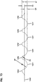
- FIG. 1 an example of media 1 useable in z-filter media construction is shown.
- the media 1 is formed from a fluted, in this instance corrugated, sheet 3 and a facing sheet 4.
- a construction such as media 1 is referred to herein as a single facer or single faced strip.
- the corrugated fluted or ridged sheet 3, Fig. 1 is of a type generally characterized herein as having a regular, curved, wave pattern of flutes, ridges or corrugations 7.
- wave pattern in this context, is meant to refer to a flute, ridge or corrugated pattern of alternating troughs 7b and ridges 7a.
- regular in this context is meant to refer to the fact that the pairs of troughs and ridges (7b, 7a) alternate with generally the same repeating corrugation (flute or ridge) shape and size.
- each trough 7b is substantially an inverse ridge for each ridge 7a.
- the term “regular” is thus meant to indicate that the corrugation (or flute) pattern comprises troughs (inverted ridges) and ridges with each pair (comprising an adjacent trough and ridge) repeating, without substantial modification in size and shape of the corrugations along at least 70% of the length of the flutes.
- the media 1 could be terminated, for example, between a pair comprising a ridge and a trough, or partially along a pair comprising a ridge and a trough.
- the media 1 depicted in fragmentary has eight complete ridges 7a and seven complete troughs 7b.
- the opposite flute ends may vary from one another. Such variations in ends are disregarded in these definitions, unless specifically stated. That is, variations in the ends of flutes are intended to be covered by the above definitions.
- the corrugation pattern is not the result of a folded or creased shape provided to the media, but rather the apex 7a of each ridge and the bottom 7b of each trough is formed along a radiused curve.
- a typical radius for such z-filter media would be at least 0.25 mm and typically would be not more than 3 mm.
- trough 7b is a concave region
- ridge 7a is a convex region.
- region 30 can be a straight segment, instead of a point, with curvature inverting at ends of the segment 30.
- a characteristic of the particular regular, wave pattern fluted (in this instance corrugated) sheet 3 shown in Fig. 1 is that the individual corrugations, ridges or flutes are generally straight, although alternatives are possible.
- straight in this context, it is meant that through at least 70%, typically at least 80% of the length, the ridges 7a and troughs (or inverted ridges) 7b do not change substantially in cross-section.
- the term "straight" in reference to corrugation pattern shown in Fig. 1 in part distinguishes the pattern from the tapered flutes of corrugated media described in Fig. 1 of WO 97/40918 and PCT Publication WO 03/47722, published June 12, 2003 .
- the tapered flutes of Fig. 1 of WO 97/40918 for example, would be a curved wave pattern, but not a "regular" pattern, or a pattern of straight flutes, as the terms are used herein.
- the media 1 has first and second opposite edges 8 and 9.
- edge 9 When the media 1 is formed into a media pack, in general edge 9 will form an inlet end or face for the media pack and edge 8 an outlet end or face, although an opposite orientation is possible.
- the various flutes 7 extend completely between the opposite edges 8, 9, but alternatives are possible. For example, they can extend to a location adjacent or near the edges, but not completely therethrough. Also, they can be stopped and started partway through the media, as for example in the media of US 2014/0208705 A1 .
- sealant bead 10 sealing the corrugated sheet 3 and the facing sheet 4 together.
- Bead 10 will sometimes be referred to as a "single facer" or “single face” bead, or by variants, since it is a bead between the corrugated sheet 3 and facing sheet 4, which forms the single facer (single faced) media strip 1.
- Sealant bead 10 seals closed individual flutes 11 adjacent edge 8, to passage of air therefrom (or thereto in an opposite flow).
- seal bead 14 In the media depicted in Fig. 1 , adjacent edge 9 is provided seal bead 14. Seal bead 14 generally closes flutes 15 to passage of unfiltered fluid therefrom (or flow therein in an opposite flow), adjacent edge 9. Bead 14 would typically be applied as media 1 is configured into a media pack. If the media pack is made from a stack of strips 1, bead 14 will form a seal between a backside 17 of facing sheet 4, and side 18 of the next adjacent corrugated sheet 3.
- bead 14 When the media 1 is cut in strips and stacked, instead of coiled, bead 14 is referenced as a “stacking bead.” (When bead 14 is used in a coiled arrangement formed from a long strip of media 1, it may be referenced as a “winding bead. ").
- seal material can be located differently, and added sealant or adhesive can even be avoided.
- the media can be folded to form an end or edge seam; or, the media can be sealed closed by alternate techniques such as ultrasound application, etc. Further, even when sealant material is used, it need not be adjacent opposite ends.
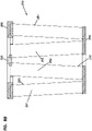
- the filter media 1 can be operated as follows. First, air in the direction of arrows 12, would enter open flutes 11 adjacent end 9. Due to the closure at end 8, by bead 10, the air would pass through the filter media 1, for example as shown by arrows 13. It could then exit the media or media pack, by passage through open ends 15a of the flutes 15, adjacent end 8 of the media pack. Of course operation could be conducted with air flow in the opposite direction.
- the parallel corrugations 7a, 7b are generally straight completely across the media, from edge 8 to edge 9.
- Straight flutes, ridges or corrugations can be deformed or folded at selected locations, especially at ends. Modifications at flute ends for closure are generally disregarded in the above definitions of "regular,” “curved” and “wave pattern. "
- the filter media is a relatively flexible material, typically a nonwoven fibrous material (of cellulose fibers, synthetic fibers or both) often including a resin therein, sometimes treated with additional materials.
- a nonwoven fibrous material of cellulose fibers, synthetic fibers or both
- it can be conformed or configured into the various corrugated patterns, without unacceptable media damage.
- it can be readily coiled or otherwise configured for use, again without unacceptable media damage.
- it must be of a nature such that it will maintain the required corrugated configuration, during use.
- the media contains a resin.
- the media can be heated to above the glass transition point of the resin. When the resin then cools, it will help to maintain the fluted shapes.
- the media of the corrugated (fluted) sheet 3 facing sheet 4 or both can be provided with a fine fiber material on one or both sides thereof, for example in accord with U.S. 6,673,136 .
- a fine fiber material on one or both sides thereof, for example in accord with U.S. 6,673,136 .
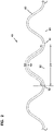
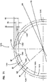
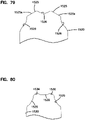
- z-filter media i.e., a z-filter media construction 40, utilizing a regular, curved, wave pattern corrugated sheet 43, and a non-corrugated flat sheet 44, i.e., a single facer strip is schematically depicted.
- the length D2 of the arcuate media for the corrugated flute 53, over the same distance D1 is of course larger than D1, due to the shape of the corrugated flute 53.
- the linear length D2 of the media 53 between points 50 and 51 will often be at least 1.2 times D1.
- D2 would be within a range of 1.2 - 2.0 times D1, inclusive.
- One particularly convenient arrangement for air filters has a configuration in which D2 is about 1.25 - 1.35 x D1.
- Such media has, for example, been used commercially in Donaldson Powercore TM Z-filter arrangements.
- Another potentially convenient size would be one in which D2 is about 1.4 - 1.6 times D1.
- the ratio D2/D1 will sometimes be characterized as the flute/flat ratio or media draw for the corrugated media.
- DCI A Flute: Flute/flat 1.52:1;
- DCI B Flute: Flute/flat 1.32:1;
- E Flute: Flute/flat 1.24:1;
- X Flute: Flute/flat 1.29:1;
- a Flute: Flute/flat 1.53:1;
- standard flute configurations from the corrugated box industry can be used to define corrugation shapes or approximate corrugation shapes for corrugated media. Comparisons above between the DCI A flute and DCI B flute, and the corrugation industry standard A and standard B flutes, indicate some convenient variations.
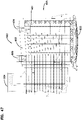
- FIG. 4 one example of a manufacturing process for making a media strip (single facer) corresponding to strip 1, Fig. 1 is shown.
- facing sheet 64 and the fluted (corrugated) sheet 66 having flutes 68 are brought together to form a media web 69, with an adhesive bead located therebetween at 70.
- the adhesive bead 70 will form a single facer bead 10, Fig. 1 .
- An optional darting process occurs at station 71 to form center darted section 72 located mid-web.
- the z-filter media or Z-media strip 74 can be cut or slit at 75 along the bead 70 to create two pieces or strips 76, 77 of z-filter media 74, each of which has an edge with a strip of sealant (single facer bead) extending between the corrugating and facing sheet.
- a strip of sealant single facer bead
- the edge with a strip of sealant would also have a set of flutes darted at this location.
- the z-filter media 74 before the z-filter media 74 is put through the darting station 71 and eventually slit at 75, it must be formed. In the schematic shown in Fig. 4 , this is done by passing a sheet of filter media 92 through a pair of corrugation rollers 94, 95. In the schematic shown in Fig. 4 , the sheet of filter media 92 is unrolled from a roll 96, wound around tension rollers 98, and then passed through a nip or bite 102 between the corrugation rollers 94, 95. The corrugation rollers 94, 95 have teeth 104 that will give the general desired shape of the corrugations after the flat sheet 92 passes through the nip 102.
- the sheet 92 After passing through the nip 102, the sheet 92 becomes corrugated across the machine direction and is referenced at 66 as the corrugated sheet.
- the corrugated sheet 66 is then secured to facing sheet 64. (The corrugation process may involve heating the media, in some instances.)
- the process also shows the facing sheet 64 being routed to the darting process station 71.
- the facing sheet 64 is depicted as being stored on a roll 106 and then directed to the corrugated sheet 66 to form the Z-media 74.
- the corrugated sheet 66 and the facing sheet 64 would typically be secured together by adhesive or by other means (for example by sonic welding).
- an adhesive line 70 is shown used to secure corrugated sheet 66 and facing sheet 64 together, as the sealant bead.
- the sealant bead for forming the facing bead could be applied as shown as 70a. If the sealant is applied at 70a, it may be desirable to put a gap in the corrugation roller 95, and possibly in both corrugation rollers 94, 95, to accommodate the bead 70a.
- Fig. 4 can be modified to provide for the tack beads 20, Fig. 1 , if desired.
- corrugation provided to the corrugated media is a matter of choice, and will be dictated by the corrugation or corrugation teeth of the corrugation rollers 94, 95.
- One useful corrugation pattern will be a regular curved wave pattern corrugation, of straight flutes or ridges, as defined herein above.
- the techniques may be applied with curved wave patterns that are not "regular," including, for example, ones that do not use straight flutes. Also, variations from the curved wave patterns shown, are possible.
- Fig. 4 shows, in cross-section, one of the flutes 68 after darting and slitting.
- a fold arrangement 118 can be seen to form a darted flute 120 with four creases 121a, 121b, 121c, 121d.
- the fold arrangement 118 includes a flat first layer or portion 122 that is secured to the facing sheet 64.
- a second layer or portion 124 is shown pressed against the first layer or portion 122.
- the second layer or portion 124 is preferably formed from folding opposite outer ends 126, 127 of the first layer or portion 122.
- two of the folds or creases 121a, 121b will generally be referred to herein as "upper, inwardly directed" folds or creases.
- the term “upper” in this context is meant to indicate that the creases lie on an upper portion of the entire fold 120, when the fold 120 is viewed in the orientation of Fig. 5 .
- the term “inwardly directed” is meant to refer to the fact that the fold line or crease line of each crease 121a, 121b, is directed toward the other.
- creases 121c, 121d will generally be referred to herein as “lower, outwardly directed” creases.
- the term “lower” in this context refers to the fact that the creases 121c, 121d are not located on the top as are creases 121a, 121b, in the orientation of Fig. 5 .
- the term “outwardly directed” is meant to indicate that the fold lines of the creases 121c, 121d are directed away from one another.
- upper and lower as used in this context are meant specifically to refer to the fold 120, when viewed from the orientation of Fig. 5 . That is, they are not meant to be otherwise indicative of direction when the fold 120 is oriented in an actual product for use.
- a regular fold arrangement 118 according to Fig. 5 in this disclosure is one which includes at least two "upper, inwardly directed, creases.” These inwardly directed creases are unique and help provide an overall arrangement in which the folding does not cause a significant encroachment on adjacent flutes.
- a third layer or portion 128 can also be seen pressed against the second layer or portion 124.
- the third layer or portion 128 is formed by folding from opposite inner ends 130, 131 of the third layer 128.
- the first layer or portion 122 is formed from an inverted ridge.
- the second layer or portion 124 corresponds to a double peak (after inverting the ridge) that is folded toward, and in preferred arrangements, folded against the inverted ridge.
- Coiled media or media pack arrangements can be provided with a variety of peripheral perimeter definitions.
- peripheral, perimeter definition and variants thereof, is meant to refer to the outside perimeter shape defined, looking at either the inlet end or the outlet end of the media or media pack.
- Typical shapes are circular as described in PCT WO 04/007054 .
- Other useable shapes are obround, some examples of obround being oval shape.
- oval shapes In general oval shapes have opposite curved ends attached by a pair of opposite sides. In some oval shapes, the opposite sides are also curved. In other oval shapes, sometimes called racetrack shapes, the opposite sides are generally straight. Racetrack shapes are described for example in PCT WO 04/007054 , and PCT application US 04/07927 , published as WO 04/082795 .
- Another way of describing the peripheral or perimeter shape is by defining the perimeter resulting from taking a cross-section through the media pack in a direction orthogonal to the winding access of the coil.
- Opposite flow ends or flow faces of the media or media pack can be provided with a variety of different definitions.
- the ends or end faces are generally flat (planer) and perpendicular to one another.
- one or both of the end faces include tapered, for example, stepped, portions which can either be defined to project axially outwardly from an axial end of the side wall of the media pack; or, to project axially inwardly from an end of the side wall of the media pack.
- the flute seals (for example from the single facer bead, winding bead or stacking bead) can be formed from a variety of materials.
- hot melt or polyurethane seals are described as possible for various applications.
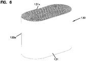
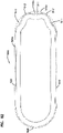
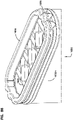
- a coiled media pack (or coiled media) 130 constructed by coiling a single strip of single faced media is depicted, generally.
- the particular coiled media pack depicted is an oval media pack 130a, specifically a racetrack shaped media pack 131.
- the tail end of the media, at the outside of the media pack 130 is shown at 131x. It will be typical to terminate that tail end along straight section of the media pack 130 for convenience and sealing.
- a hot melt seal bead or seal bead is positioned along that tail end to ensure sealing.
- the opposite flow (end) faces are designated at 132, 133. One would be an inlet flow face, the other an outlet flow face.
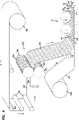
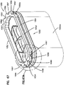
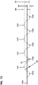
- Fig. 7 there is (schematically) shown a step of forming stacked z-filter media (or media pack) from strips of z-filter media, each strip being a fluted sheet secured to a facing sheet.
- single facer strip 200 is being shown added to a stack 201 of strips 202 analogous to strip 200.
- Strip 200 can be cut from either of strips 76, 77, Fig. 4 .
- application of a stacking bead 206 is shown, between each layer corresponding to a strip 200, 202 at an opposite edge from the single facer bead or seal. (Stacking can also be done with each layer being added to the bottom of the stack, as opposed to the top.)
- each strip 200, 202 has front and rear edges 207, 208 and opposite side edges 209a, 209b.
- Inlet and outlet flutes of the corrugated sheet/facing sheet combination comprising each strip 200, 202 generally extend between the front and rear edges 207, 208, and parallel to side edges 209a, 209b.
- opposite flow faces are indicated at 210, 211.
- the stacking bead 206 is positioned adjacent the upstream or inlet face 211; in others the opposite is true.
- the flow faces 210, 211 extend between opposite side faces 220, 221.
- the stacked media configuration or pack 201 shown being formed in Fig. 7 is sometimes referred to herein as a "blocked" stacked media pack.
- the term "blocked” in this context is an indication that the arrangement is formed to a rectangular block in which all faces are 90° relative to all adjoining wall faces.
- the stack can be created with each strip 200 being slightly offset from alignment with an adjacent strip, to create a parallelogram or slanted block shape, with the inlet face and outlet face parallel to one another, but not perpendicular to upper and bottom surfaces.
- the media or media pack will be referenced as having a parallelogram shape in any cross-section, meaning that any two opposite side faces extend generally parallel to one another.
- more than one stack can be incorporated into a single media pack.
- the stack can be generated with one or more flow faces that have a recess therein, for example, as shown in US 7,625,419 .
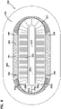
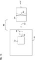
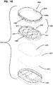
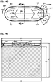
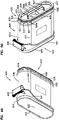
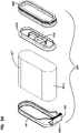
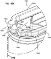
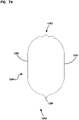
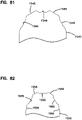
- Figs. 8-8B An example of such alternate media arrangement or pack is depicted in Figs. 8-8B .
- the media of Figs. 8-8B is analogous to one depicted and described in DE 20 2008 017 059 U1 ; and as can sometimes found in arrangements available under the mark "IQORON" from Mann & Hummel.
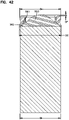
- the media or media pack 250 comprises a first outer pleated (ridged) media loop 251 and a second, inner, pleated (ridged) media loop 252, each with pleat tips (or ridges) extending between opposite flow ends.
- the view of Fig. 8 is toward a media pack (flow) end 255.
- the end 255 depicted can be an inlet (flow) end or an outlet (flow) end, depending on selected flow direction.
- end 255 is an inlet flow end.
- the outer pleated (ridged) media loop 251 is configured in an oval shape, though alternatives are possible.
- a pleat end closure for example molded in place, is depicted closing ends of the pleats or ridges 251 at media pack end 255.
- Pleats, or ridges 252 are positioned surrounded by and spaced from loop 251, and thus pleated media loop 252 is also depicted in a somewhat oval configuration. In this instance, ends 252e of individual pleats or ridges 252p in a loop 252 are sealed closed. Also, loop 252 surrounds the center 252c that is closed by a center strip 253 of material, typically molded-in-place.
- end 255 is an inlet flow end
- air enters gap 265 between the two loops of media 251, 252.
- the air then flows either through loop 251 or loop 252, as it moves through the media pack 250, with filtering.
- loop 251 is configured slanting inwardly toward loop 252, in extension away from end 255. Also spacers 266 are shown supporting a centering ring 267 that surrounds an end of the loop 252, for structural integrity.
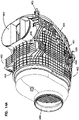
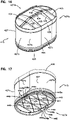
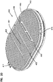
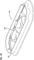
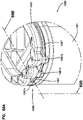
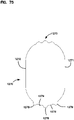
- FIG. 8A an end 256 of the cartridge 250, opposite end 255 is viewable.
- an interior of loop 252 can be seen, surrounding an open gas flow region 270.
- air that has entered media loop 251, Fig. 8 during filtering would generally pass around (over) an outer perimeter 256p of end 256.
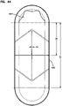
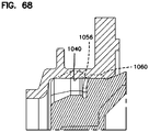
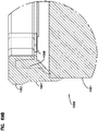
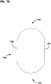
- Fig. 8B a schematic cross sectional view of cartridge 250 is provided. Selected identified and described features are indicated by like reference numerals
- the cartridge 250 described is generally a cartridge which has media tips extending in a longitudinal direction between opposite flow ends 255, 256.
- the media pack 250 is depicted with an oval, in particular racetrack, shaped perimeter. It is depicted in this manner, since the air filter cartridges in many examples below also have an oval or racetrack shaped configuration. However, the principles can be embodied in a variety of alternate peripheral shapes.
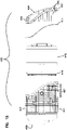
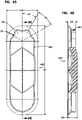
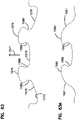
- FIGs. 9-12 some schematic, fragmentary, cross-sectional views are provided of still further alternate variations of media types that can be used in selected applications of the principles characterized herein. Certain examples are described in USSN 62/077,749, filed November 10, 2014 and owned by the Assignee of the present disclosure, Donaldson Company, Inc.
- each of the arrangements of Figs. 9-12 represents a media type that can be stacked or coiled into an arrangement that has opposite inlet and outlet flow ends (or faces), with straight through flow.
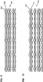
- FIG. 9 an example media arrangement 301 from USSN 62/077,749 (2658) is depicted, in which an embossed sheet 302 is secured to a non-embossed sheet 303, then stacked and coiled into a media pack, with seals along opposite edges of the type previously described for Fig. 1 herein.
- FIG. 10 an alternate example media pack 310 from USSN 62/077,749 is depicted, in which a first embossed sheet 311 is secured to a second embossed sheet 312 and then formed into a stacked or coiled media pack arrangement, having edge seals generally in accord with Fig. 1 herein.
- a third example media arrangement 320 from USSN 62/077,749 is depicted, in which a sheet 321, which is embossed on both sides, is secured to another layer 322 of a similar media, but inverted, and stacked or coiled into a media pack 320, with edge seals somewhat analogous to Fig. 1 .
- Edge seals can be conducted in either the upstream end or the downstream end, or in some instances both. Especially when the media is likely to encounter chemical material during filtering, it may be desirable to avoid a typical adhesive or sealant.
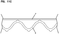
- Fig. 11A a cross-section is depicted in which the fluted sheet X has various embossments on it for engagement with the facing sheet Y. Again these can be separate, or sections of the same media sheet.
- Fig. 11B a schematic depiction of such an arrangement between the fluted sheet X and facing sheet Y is also shown.
- a still further variation of such a principle is shown between a fluted sheet X and a facing sheet Y. These are meant to help understand how a wide variety of approaches are possible.
- a fluted sheet 6402 is secured to a facing sheet 6403.
- the facing sheet 6403 may be a flat sheet.
- the media arrangement 6401 can then be stacked or coiled into a media pack, with seals along opposite edges of the type previously described for Fig. 1 herein.
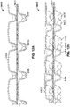
- the flutes 6404 of fluted sheet 6402 have an undulating ridgeline including a series of peaks 6405 and saddles 6406.
- the peaks 6405 of adjacent flutes 6404 can be either aligned as shown in Figs. 12A and 12B or offset. Further the peak height and/or density can increase, decrease, or remain constant along the length of the flutes 6404.
- the ratio of the peak flute height to saddle flute height can vary from about 1.5, typically from 1.1 to about 1.
- the same media be used for the fluted sheet section and the facing sheet section.
- a different media can be desirable in each, to obtain different effects.
- one may be a cellulose media, while the other is a media containing some non-cellulose fiber. They may be provided with different porosity or different structural characteristics, to achieve desired results.
- the fluted sheet section or the facing sheet section can include a cellulose material, synthetic material, or a mixture thereof.
- one of the fluted sheet section and the facing sheet section includes a cellulose material and the other of the fluted sheet section and facing sheet section includes a synthetic material.
- Synthetic material(s) can include polymeric fibers, such as polyolefin, polyamide, polyester, polyvinyl chloride, polyvinyl alcohol (of various degrees of hydrolysis), and polyvinyl acetate fibers.
- Suitable synthetic fibers include, for example, polyethylene terephthalate, polyethylene, polypropylene, nylon, and rayon fibers.
- Other suitable synthetic fibers include those made from thermoplastic polymers, cellulosic and other fibers coated with thermoplastic polymers, and multi-component fibers in which at least one of the components includes a thermoplastic polymer.
- Single and multi-component fibers can be manufactured from polyester, polyethylene, polypropylene, and other conventional thermoplastic fibrous materials.
- Figs. 9-12B are meant to indicate generally that a variety alternate media packs can be used in accord with the principles herein. Attention is also directed to USSN 62/077,749 with respect to the general principles of construction and application of some alternates media types.
- the techniques characterized herein will preferably be applied when the media is oriented for filtering between opposite flow ends of the cartridge is media having flutes or pleat tips that extend in a direction between those opposite ends.
- the techniques characterized herein with respect to seal arrangement definition can be applied in filter cartridges that have opposite flow ends, with media positioned to filter fluid flow between those ends, even when the media does not include flutes or pleat tips extending in a direction between those ends.
- the media for example, can be depth media, can be pleated in an alternate direction, or it can be a non-pleated material.
- the techniques described herein were typically developed for advantageous application and arrangements involving media packs with straight through flow configurations, the techniques can be applied to advantage in other systems.
- the techniques can be applied when the cartridge comprises media surrounding a central interior, in which the cartridge has an open end.
- Such arrangements can involve "forward flow” in which air to be filtered enters the central open interior by passage through the media, and the exits through the open end; or, with reverse flow in which air to be filtered enters the open end and then turns and passes through the media.
- a variety of such arrangements are possible, including pleated media and alternate types of media. Configurations usable would include cylindrical and conical, among others.
- the equipment system 360 in the example, comprises a vehicle or other equipment 361 having an internal combustion engine arrangement 362 with a combustion air intake 363.
- the equipment arrangement 360 includes an air cleaner system 365 having a filter arrangement 366 therein, typically comprising a serviceable (i.e. removable and replaceable) filter cartridge.
- Intake air to the system is shown at 367 directed into the air cleaner assembly 365 before filtering of unfiltered air through media of the filter cartridge arrangement 366.
- filtered air is shown being directed into the equipment air intake 363.
- optional equipment such as turbo system is shown.
- the equipment system can be for example, an industrial air filter, an air cleaner arrangement used in association with a turbine, etc.
- the use in association with an internal combustion engine is typical, but not specifically required for many of the principles characterized herein.
- air cleaners such as used to filter equipment intake air, comprise housings having positioned therein at least a main filter cartridge, and sometimes, a safety.
- the main filter cartridge generally is constructed to collect particulate contaminant as it flows into the air intake stream for the equipment. This protects the equipment against damage.
- Such filter cartridges are generally configured to be removed and replaced, i.e. they are service parts. At various defined service intervals, and/or as increase in restriction (from dust load) becomes an issue, the cartridges are removed from the air cleaner and are refurbished or replaced.
- the cartridges are specifically designed to match the equipment manufacturers' requirements for operation. It is important to ensure that the cartridge, which is replaced in the field, is a proper one for the equipment involved, and, thus fits and seals properly.
- a primary interface between the filter cartridge and the air cleaner is along a housing seal. This interface has sometimes been used to help ensure that a cartridge that fits is also a proper one for the system of interest. Examples are provided by the descriptions of U.S. 8,864,866 . In that particular reference, seal surface variations through projections and/or recesses are described, in general terms. Those general principles are applied herein, with improvements and variations for certain applications.
- a housing seal positioned on the filter cartridge is a "radial” or “radially directed” seal.
- reference is meant to a seal that is used to apply compressive seal forces directed either: generally toward a surrounding portion of a housing; or, alternately, with seal forces directed toward a portion of housing surrounded by the seal, for the sealing during use.
- a radial seal will generally be a seal that surrounds a flow passageway, with primary compressive direction (when installed) being toward or away from that flow passageway.
- An outwardly or radially outwardly directed seal will be one which has a seal surface on the seal arrangement (of the cartridge) that sealingly engages a surrounding structure in use.
- a radially inwardly directed seal is a seal arrangement in which the seal surface of the cartridge surrounds the structure to which it sealed during use.
- the seal surface to be engaged by a seal on the cartridge is deeply recessed within a housing, and out of view of the service provider.
- An issue with using cartridges having seals which are not merely of simple or uniform geometric shape, such as circular or oval is that it, can be difficult, depending on the design, to orient the cartridge appropriately for the sealing to properly occur during installation.
- side load reference is meant to the portion of the housing through which the cartridge is installed in use.
- a straight through flow cartridge is loaded through the side of a housing and then pushed sideways into a sealing positioned. It can be difficult to manipulate and leverage the cartridge appropriately to get good sealing. Examples of advantageous side load arrangements with useful features to facilitate loading are described, for example in U.S. 7,396,375 ; U.S. 7,655,074 ; U.S. 7,905,936 ; U.S. 7,713,321 and U.S. 7,972,404 .
- FIG. 14-22 Selected principles according to the present disclosure can be understood from reference to Figs. 14-22 .
- the example depicted, as will be understood from the following, is an air cleaner assembly with a main filter cartridge removably installed therein. Further, the assembly is configured as "end load", meaning that that the housing access cover is located at an opposite end of the cartridge from an air flow outlet.
- end load meaning that that the housing access cover is located at an opposite end of the cartridge from an air flow outlet.
- the principles can be applied in alternate housing configurations.
- the air cleaner assembly 400 generally indicates an air cleaner assembly in accord with selected principles according to the present disclosure.
- the air cleaner assembly 400 comprises a housing 401.
- the housing 401 generally includes a main body 403 and an access cover 404, in this instance secured in place by latches 405.
- the access cover 404 is fully removable from the housing body 403, but the principles can be applied in alternate arrangements.
- the housing 401 generally defines an air flow inlet arrangement 407 and an air flow outlet arrangement 408. Air to be filtered enters the housing 401 through inlet 407 passes through an internally positioned filter arrangement, with filtered air exiting through outlet arrangement 408.
- inlet flow through inlet arrangement 407 is generally perpendicular to air flow through a cartridge installed in the housing, and air flow through outlet arrangement 408 is generally in alignment with a direction of air flow through an installed filter cartridge, in use, but the principles can be practiced in alternate arrangements.
- Fig. 14 no specific effort is made to indicate an orientation within equipment for use.
- the assembly 400 can be oriented for use, with one of the sides, for example, the side facing the viewer in Fig. 14 , directed upwardly, directly downwardly, or oriented laterally.
- the principles described herein can be applied in a variety of such arrangements and no specific orientation is required. Indeed, this can be an advantage of arrangements according to the present disclosure.
- FIG. 14A a selected perspective view of the assembly 400 is depicted. Like features to those already identified are indicated by similar reference numerals.
- the housing 401 depicted optionally includes various mounting pads 409 thereon by which it can be secured to equipment.
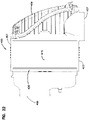
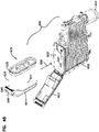
- FIG. 15 an exploded elevational view of the air cleaner assembly 400 is depicted.
- access cover 404 is shown removed from body 403, for access to interior features.
- Optional weather gasket 411 is depicted. It can be secured to one or the other of the access cover 404 in body 403 if desired, or it can be a separate item.
- the weather gasket 411 is a gasket that will help provide a weather seal between the access cover 404 and body 403 when installed, for example to inhibit migration of water (for example, from rain) from entering the interior of the housing 401.
- both the inlet arrangement 407 and outlet arrangement 405 are shown depicted on the main body 403; alternatives are possible. Also, as indicated previously, the inlet and outlet arrangements 407/408 can be alternately located or directed.
- the air cleaner assembly 400 includes an interiorly received, removable and replaceable (i.e. serviceable) main filter cartridge 415.
- the assembly 400 is also depicted having an optional safety filter cartridge 416.
- the safety filter cartridge 416 is positioned downstream of the main filter cartridge 415 in use.
- the main filter cartridge 415 is the cartridge responsible for collection of the majority of particulate material separated from the air flow stream, during use.
- the safety filter cartridge 416 provides a variety of functions. It can be left in place when the main filter cartridge 415 is removed and serviced, thus protecting the outlet for clean air from dust being knocked off inside the housing and grating thereto.
- the filter cartridge safety 416 can also collect some dust should there be a failure in the media or seal of the main filter cartridge 415.
- These are well known uses of safety filter cartridges.
- the particular safety filter cartridge 416 depicted, is generally of a type known, see for example, U.S. 7,905,936 .
- Fig. 15A an exploded perspective view of the assembly 400 is depicted, allowing further review of general components previously discussed. Attention is directed to the safety filter cartridge 416, and, in particular, to installation projection 417 and handle or handle arrangement 418. Such features are described, for example in U.S. 7,905,936 , referenced above, and incorporate herein by reference.
- the service provider would push the safety filter cartridge 416 into the housing body 403, engaging the projection 417 with a receiver appropriately positioned in body 403. In this manner, the user can leverage the safety filter cartridge 416 into position, using the handle 418.
- the particular safety filer cartridge 416 depicted uses a peripheral seal 419 that will engage (as a radial seal) a surrounding portion of the housing, when the safety 416 is properly installed.
- the safety 416 uses an outwardly directed radial seal in the terms characterized herein above.
- the assembly 400 depicted is one in which the main filter cartridge 415 is installed through an end load, in accord with the characterizations of such terms above.
- the main cartridge 415 is pushed into the housing body 403 during installation, and toward an outlet end or outlet arrangement 408.
- the main filter cartridge 415 includes a seal arrangement 420 on an end of the cartridge 415 that is recessed most deeply in the housing body 403 during installation. In the example depicted, this is a downstream air flow outlet end at the cartridge 415.
- the main filter cartridge 415 generally comprises a media pack configured for straight through flow having opposite flow ends 424, 425.
- flow end when used in characterizing the media pack 427, or filter cartridge 415, reference is meant to an end face or region into which (or from which) air flows during use.
- the flow ends are planar, but alternatives are possible.
- one of the ends will be an inlet flow end, and an opposite end will be an outlet flow end.
- flow end 424 is an inlet flow end and flow end 425 is an outlet flow end.
- the media pack 427 generally comprises air filtration media that is closed to passage of inlet air entering the cartridge at inlet end 424 from exiting outlet flow 425 without filtering passage through the media.
- the filter cartridge 415 generally comprises media pack 427.
- the media pack comprises media appropriate for the filtration operation to be conducted, generally with an air flow through the opposite ends.
- the media characterized above in connection with Figs. 1-12B can be used.
- the particular example media pack 429 depicted has a generally oval shape, with opposite curved ends 427a, 427b, typically approximately semi-circular, and with relatively straight (opposite) first and second side sections 427c, 427d extending therebetween.
- Such a media pack can be made from a coiled strip of corrugated media secured to facing media in accord with descriptions above, but alternatives are possible.
- the particular media pack 427 depicted would typically be constructed without a center core, for example in accord with the techniques of U.S. 8,226,786 , but alternatives, including ones in which a center core is provided, are possible.
- the media pack 427 may include an outer sheath, shield or protective coating surrounding it.
- the outer surface 427s of the media pack 427 along much of the exposed length of the media pack will comprise facing media with no outer protective coating other than, perhaps, a label.
- main filter cartridges will include one or more optional "preforms" thereon.
- preform and variants thereof in this context, reference is meant to a structural piece that is typically premade, for example molded from plastic, and is then secured to the media pack the filter cartridge using adhesive or sealant material or other material that is cured or set.
- Preforms generally, are well known, see for example U.S. 7,905,936 ; U.S. 7,713,321 and U.S. 7,972,404 .
- the particular cartridge 415 of Figs. 16-19 includes two such optional preforms, indicated generally at 430, 431.
- the preform 430 is positioned adjacent end 424. It includes an installation handle arrangement 434, in the example depicted, in axial overlap with flow end 424; and, a perimeter arrangement 435 that surrounds media pack 427.
- the preform 430 can be positioned in place and be secured by an adhesive if desired, or with seal material. However, since preform 430 is positioned upstream of housing seal arrangement 420, a seal between preform 430 and the media pack 427 is not critical.
- preform 430 also includes an optional end grid arrangement 435 in axial alignment with end 424 of the media. The end grid 435 can provide strength, structure and integrity to both the preform 430 and to the media of media pack 427.
- preform 431 is positioned adjacent flow end 425.
- Preform 431 is a seal support preform and includes an optional grid 440 thereon to stabilize the media end 425 against distortion.
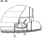
- preform 431 includes a seal support 441 thereon, discussed below, and positioned to support sealing pressure against seal material 445 of the seal arrangement 420 in use.
- seal arrangements 420 can be used.
- the particular arrangement depicted uses a seal arrangement in which seal material is molded-in-place to secure preform 431 in position and to also form a seal surface 445a of seal material 445.
- Techniques such as those described in U.S. 7,396,376 and U.S. 8,409,316 can be used, but alternatives are possible.
- Fig. 18 an exploded perspective view of the filter cartridge 415.
- seal support flange 447 which, it will be understood, projects to appropriate portions of the seal arrangement 420 to support the seal material 445 during sealing.
- FIG. 19 an alternate exploded perspective view is shown, taken generally toward flow end 424 of the cartridge 415.
- the particular seal arrangement 420 is depicted with a seal surface 445a that is configured to form an outwardly directed radial seal. That is, it is positioned in the cartridge 415 at a location to form a seal, during installation, with a surrounding portion (housing structure) of an air cleaner (typically an internal housing portion).
- the seal surface 445a can be configured to surround a portion of the air cleaner (typically an internal housing portion) during installation, and thus from a radially inwardly directed seal.
- the radial seal depicted is a "supported seal" in that the support flange 447 of the preform 431 is positioned to support the seal material 445 during installation, such that the material 445 is, at least in part, compressed between the support flange 431 and a housing surface, during use.
- Seal supports that operate in this general manner are well known.
- the particular seal surface 445 of the example arrangement 415 depicted uses an optional modified oval shape.
- it is not simply an oval shape in which straight or oppositely arcuate seal sections are positioned between two opposite curved (for example semi-circular) ends, as would be the case with oval racetrack shaped seals of arrangements such as U.S. 7,905,936 .
- It rather uses a specific arrangement of positioned variations in that surface, to achieve advantage.
- Such variations can be of the type related to those generally described in U.S. 8,864,866 .
- specific selected configurations and variations can include features discussed herein, to advantage.
- the advantageous non-straight sections of the seal surface are indicated generally at 448 as comprising alternating projection sections 448p and recess sections 448r, discussed further below.
- the support flange 447 includes similar projection/recess sections at 449 to provide support to the seal arrangement in the related seal sections.
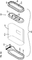
- the safety filter 416 comprises a preform 450 having media, typically pleated media 451, positioned therein.
- the preform 450 has an outer perimeter rim 452 including projection 417 previously discussed.
- Pleat spacers are indicated in the preform at 453.
- Handle arrangement 418 is shown, for managing the safety.
- seal member 419 secured in place, typically by an adhesive. Alternates are possible.
- the seal configuration of the main filter cartridge 415 is selected to have a configuration that can be unique to the system of concern, if desired, to prevent installation of alternate arrangements, and also to be of a type that can be safely and securely established and released.
- the particular arrangement depicted has a general oval perimeter with two opposite curved (semi-circular) ends, engaged by opposite sections of the seal arrangement that are not straight.
- the particular configuration depicted for the not straight section may sometimes be referred to as a "wavy section" as discussed in more detail below. It is generally a section having a projection/recess contour as described below. Engagement of such arrangements for sealing can be understood by reference to Figs. 21 , 21A and 22 .
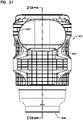
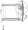
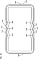
- Fig. 21 a plan view of the housing 401 taken toward the inlet 407 is depicted. In this view, no cartridge is positioned in the housing. Fig. 21 can be seen as providing the orientation for Fig. 21A .
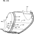
- Fig. 21A is a cross-sectional view taken generally along line 21A-21A, Fig. 21 .
- a housing seal surface (or structure) 460 positioned within the housing, in this instance which will surround the cartridge seal arrangement 420 when installed, and against which the seal arrangement 420 and thus the cartridge 415 will seal when installed.
- the seal surface 460 and the arrangement depicted, which uses an outwardly directed radial seal, is a seal surface that surrounds the seal arrangement 420 in use, and against which the seal surface 445a is pressed during use.
- the seal surface 460 depicted includes smooth (non-wavy) sections 461 and wavy or projection/recess sections 462.
- the wavy or projection/recess sections 462 are sections of surface 460 which comprise an alternating projection/recess configuration for sealing engagement with one or more of mating wavy surfaces 448, Fig. 18 , in the cartridge 415.
- the particular cross-section depicted in Fig. 21A shows approximately half the overall surface 460, the opposite half of surface 460 typically being a mirror image.
- two wavy (or projection/recess) sections 462 in the example each comprising three inwardly directed projections 465 with two outwardly projecting sections 466 therebetween.
- the sections can be characterized as "inwardly facing convex" for sections 465; and, inwardly facing concave" for sections 466, if desired.
- Alternatives are possible.
- housing seal surfaces 460 of the type usable in an arrangement involving principles described herein generally can be features molded as a portion of a molded housing, if desired.
- FIG. 22 a schematic depiction is provided of the housing 401 with cartridge 405 positioned therein.
- Figs. 14-22 are intended to show an example arrangement using selected principles according to the present disclosure.
- the features can be implemented in a wide variety of variations with respect to housing features, cartridge features, and indeed, with respect to specific seal configurations.
- seal configurations general principles are provided herein after additional embodiments and examples are shown.
- the cartridge depicted includes an installation handle 434 as previously characterized. It can be seen by reference to the various figures, that the handle 434 is positioned in overlap with an inlet flow end of the media pack, and can be used to push the cartridge into position or pull the cartridge from sealing, during servicing.
- This type of handle 434 will sometimes be referred to as an "installation handle” characterized for an axial direction of installation and removal.
- a first example variation from the cartridge 415 is depicted.
- a preform such as preform 430, Fig. 19 , could be used in arrangements in accord with Figs. 23-34 , if desired.
- cartridge 480 generally comprises a media pack 481 and seal arrangement 482.
- the media pack 481 may generally be constructed in accord with principles described herein above, and indeed, may be generally in accord with media pack 427, Fig. 16-19 .
- the cartridge 480 includes opposite flow ends 484, 485.
- the seal arrangement 482 is positioned at flow end 485. While alternatives are possible, in a typical application, it is expected that 484 would be an inlet flow end and 485 would be an outlet flow end, for the media pack 481.
- the absence of a handle arrangement adjacent flow end 484 is not meant to indicate that the cartridge 480 is not pushed in (and removed) by grasping that end. Rather, it is meant to indicate that in some instances, the cartridge 480 and assembly can be configured such that one can grasp and manipulate the cartridge into and out of sealing orientation without the need for a handle arrangement at an end opposite from the housing seal arrangement.
- seal arrangement 482 generally comprises a seal member 489 molded-in-place.
- the seal member 489 includes a seal surface 489s.
- the seal surface 489s depicted is an outwardly directed surface, configured to form an outwardly directed radial seal in accord with the principles described above. Alternatives are possible.
- seal surface 489s has a shape similar, in overall feature, to the surface 448s, Figs. 16 and 17 .
- Fig. 24 a plan view of the cartridge 480 is depicted, taken toward surface 485 and seal arrangement 482.
- Cross-sectional views are indicated generally at Figs. 25 and 26 .
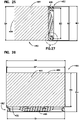
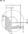
- Fig. 27 an enlarged fragmentary view of the portion of Fig. 25 is shown.
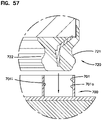
- the seal arrangement 482 depicted comprises a molded-in-place seal portion 489 and a seal support preform 490.
- the preform 490 depicted includes a seal support flange 491 thereon.
- seal surface 490s generally has a shape which tapers from a largest diameter portion 489x toward an insertion tip 490t.
- the particular taper depicted is a stepped arrangement. However, straight chamfer arrangements are possible. This facilitates installation and is well known for a wide variety of radial seal types, see for example U.S. 7,396,376 and U.S. 8,409,316 .
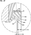
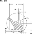
- Figs. 28-29C the molded seal portion 489 is shown separate from the cartridge and preform.
- Fig. 28 is a plan view taken from an orientation analogous to Fig. 24 .
- Fig. 29 is a perspective view, and Figs. 29A, 29B , and, 29C are cross-sectional views.
- Figs. 30-34 the seal support preform 490 is depicted.
- Fig. 30 a perspective view is taken toward handle 488 is shown.
- Fig. 31 a plan view taken toward handle 488 is shown.
- Figs. 32, 33 and 34 cross-sectional views are shown.
- Figs. 23-34 some example dimensions are provided. These are intended to indicate a workable arrangement using principles according to the present disclosure. Variations in the dimensions are possible.
- a maximum thickness of the molded-in-place seal section (between seal surface and support) in alignment with the seal support is at least 10 mm and usually not greater than 20 mm (often 12-16 mm) although alternatives are possible.
- Positioning of a handle adjacent the seal end can provide some advantage. For example, when such a cartridge is handled, typically a service provider will handle the cartridge from the handle end and set it down with the cartridge directed upwardly. This will help keep the seal material 489 from being in contact with work surfaces, etc. during handling.
- the seal surfaces were configured with two semi-circular curved ends, having opposite sections extending therebetween, defining a general oval shape, modified to include one or more wavy or projection/recess sections in what would have otherwise have been straight sections in the (respective) oval shape. It is possible to implement principles of the present disclosure in alternate arrangements including at least one wavy or projection/recess section in an otherwise end curve of the oval shape, either as an alternative, or in addition to features discussed. Some examples are described in this section and the recited figures.
- a first example filter cartridge and features therefore, are schematically depicted, having a wavy (or projection/recess) section in an arcuate "end" of the seal arrangement in accord with the principles described herein.
- Fig. 35 a schematic perspective view of such a cartridge is shown at 500.
- the cartridge 500 would include a media pack 501 (shown in phantom) with opposite flow ends 502, 503. It is noted that the media pack 501 is depicted in phantom, but may be similar to the configurations of previously described media packs herein, and using media in accord with discussions above.
- the seal arrangement 505 includes a seal member 506 configured with a seal surface 506s.
- the particular seal member 506 depicted is configured using molded-in-place material as previously discussed, and positioned with surface 506s configured as an outwardly directed radial seal, i.e. to seal against a surrounding portion of a housing in use, alternatives are possible.
- a plan view of cartridge 500 is depicted, taken towards seal arrangement 505.
- Seal ring 506 comprising seal surface 506s is shown depicting the perimeter shape thereof.
- surface 506s can be seen as having a first end portion 508, opposite side portions 509, 510 and end portion 510x, opposite portion 508.
- the perimeter shape is generally oval, except for modifications at end 510 as discussed below.
- end 508 is arcuate (in the example generally semi-circular) in perimeter shape, and opposite sections 509, 510 are generally straight and parallel to one another.
- Alternatives are possible.
- end 510x can be seen extending around a 180° arc, but having a surface region configured with a wavy or projection/recess shape, comprising alternating recess sections 511 and projection sections 512.
- Fig. 37 a cross-sectional view of molded-in-place seal material 505 of seal arrangement 505 taken along line 37-37, Fig. 36 is depicted. Regions 513 show where the molded-in-place portion would receive a support projection on a preform. Regions 514 show over molded portions to secure the seal the seal material (and preform) to the media pack.
- Fig. 38 a cross-sectional view taken generally along line 38-38, Fig. 37 is shown.
- a seal support preform arrangement includes a handle thereon, at the same end of the cartridge as the seal arrangement.
- An example is provided in Figs. 39-46 as follows.
- FIG. 39 an example cartridge 550 is depicted, comprising media pack 551 and seal arrangement 552. These may be generally in accord with the arrangement of Figs. 35-38 except for the presence of a handle arrangement 553, in overlap with an end 555 of media 551.
- the seal arrangement 551 comprises a molded-in-place region 555 of material including a region 556 having seal surface 556s.
- the media pack 550 may generally be as previously described having opposite flow ends 558, 559.
- Fig. 40 a plan view taken toward flow end 559 is depicted.
- Fig. 41 a cross-sectional view taken along line 41-41, Fig. 40 is shown.
- Fig. 42 a cross-sectional view taken along line 42-42, Fig. 40 is shown.
- preform 560 can be seen with seal support 561
- Fig. 43 the preform 560 is shown in perspective.
- Fig. 44 a plan view is shown taken toward an end opposite flange 561.
- Fig. 45 an opposite plan view, toward flange 461, is shown.
- Fig. 46 a cross-sectional view taken along line 46-46, Fig. 45 is shown.
- FIGs. 47-56 an example air cleaner assembly is depicted, usable with the main filter cartridge having seal characteristics similar to those described above in the embodiments of Figs. 35-38 and/or Figs. 39-45 .
- the air cleaner assembly 600 comprises a housing 601 including a housing body 602, and service access cover 603.
- a variation from a previously described housing 401 is shown in the access cover 603 is not removed from the housing body 602, when the access cover 603 is opened. Rather, it remains secured to the housing body.
- Alternatives are possible; and, the variation can be used with the assembly 400, Fig. 14 .
- FIG. 47 other features viewable include a filtered air flow outlet arrangement 604, by which filtered air leaves the housing to be directed downstream equipment. Air to be filtered would generally enter the housing through an inlet at end 605. At 606, optional mounting pads are shown to facilitate mounting to equipment in use. The pads 606 can be located in a variety of locations, to facilitate securement.
- Fig. 47 From the orientation depicted in Fig. 47 , no specific characterization is meant with respect to how the whole housing 601 and overall assembly 600 will be oriented in use.
- the assembly 600 could be positioned with the side view facing the view in Fig. 47 directed upwardly or downwardly. However, it could also be oriented with outlet 604 directed upwardly or downwardly.
- FIG. 48 an exploded view of air cleaner assembly 600 is depicted with the access cover 603 pivoted open.
- An internally received cartridge 620 is shown exploded from interior 602i of body 602.
- the example air cleaner assembly 600 depicted is a "side load" assembly that term is used herein. That is, the cartridge 620 is inserted into and removed from the housing body 602 through a side thereof, in between inlet 605 and outlet 604. This means, generally, that two types of movements to the cartridge 620 are needed during installation. In a first, see arrow 609, direction generally perpendicular to air flow through the cartridge 620, the cartridge 620 is inserted into the housing body 602.
- FIGs. 49 and 50 perspective views of the cartridge 620 are shown.
- the cartridge 620 can be seen as comprising a media pack 621 having opposite flow ends 622, 623.
- a seal arrangement 625 is depicted.
- the seal arrangement 625 can be generally in accord with seal arrangement 552, Figs. 39-40 , although variations can be used.
- it includes a seal member 626 forming a seal surface 626s configured to form an outwardly directed radial seal; the seal surface 626s having a perimeter shape with an arcuate, semi-circular, curved end 627; opposite straight side sections 628, 629; and, a curved end, opposite end 627, at 630.
- End 630 comprises a wavy or projection/recess configuration having three recess sections 631 and two projection sections 632.
- a seal support preform 635 including a handle portion 636 and a support region 637 ( Fig. 53 ) to support the seal, is shown.
- the seal arrangement 625 can be secured in place by an over mold at 638, Fig. 49 , of a type similar to those described above.
- a second preform 640 is depicted having: a band portion 641 surrounding the media 620; an end rim portion 642 extending over a portion of end 622; and, an installation handle arrangement 645.
- the particular handle arrangement 625 is positioned in overlap with a curved end 621a of the oval media pack 621.
- the handle arrangement 645 is aligned with the same curved end 621a of the media pack 621 as is the wavy (projection/recess) end section 630 of the seal surface 626s discussed previously. Advantages from this are discussed below, although alternatives are possible.
- Fig. 51 a side elevational view of filter cartridge 620 provided with features as described is indicated.
- Fig. 52 and end view taken toward end 623 is shown, with features discussed as indicated.
- FIG. 53 an exploded view is shown, with features as indicated.
- Fig. 54 an alternate schematic exploded perspective view analogous to Fig. 53 is shown.
- the handle arrangement 645 is positioned to facilitate installation when oriented adjacent the same curved end 621a of the media pack 621 as is the wavy section 630. This is because during a side installation, the end arcuate section 627 of the seal arrangement opposite the arcuate wavy (projection/recess) section 630 can be first nested, or partially nested, with the user then manipulating the handle 645 to fully engage the seal, and complete the installation. In this type of operation, the non-wavy arcuate section 627 of the seal opposite the wavy section 630 facilitates installation.
- the handle arrangement 645 can also be used as a part of a projection arrangement to be engaged by the access cover 603 securing the cartridge in position.
- An example of this is shown in Figs. 55-56 .
- the access cover 603 can, thus, have a variety of features that help support the cartridge 620 against undesired movement during installation.
- the seal arrangements shown are of a type that engage a surrounding portion of housing structure.
- the seals can be formed through installation into a trough or other receiving arrangement in a housing, in use.
- the above principles can be understood, for example, from the fragmentary, schematic view of Fig. 57 .
- the housing structure arrangement 700 is depicted, comprising a receiving trough 701 for a seal arrangement during use.
- a seal arrangement 720 is shown insertable into the trough 701.
- the seal arrangement 720 may comprise a radially outwardly directed seal member or surface 721 as shown, for engagement with an outer flange 701o on the trough 701.
- the seal arrangement 720 can comprise a radially inwardly directed seal surface 722 oriented and configured to engage an inner surface or flange 701i of trough 701 in use.
- a seal arrangement having an inwardly directed radial seal at 730 is shown.
- a seal arrangement having both an outwardly directed seal arrangement 731 and an inwardly directed seal arrangement 732 is shown.
- Fig. 60 is a schematic representation of a (non-arcuate) but wavy (projection/recess) seal surface section usable in selected arrangements according to the present disclosure.
- Fig. 60 can be viewed as a schematic representation of a perimeter portion of a wavy seal surface section of the example of Fig. 24 .
- Fig. 61 is of an arcuate wavy (projection/recess) surface section usable in selected arrangements according to the presented disclosure.
- Fig. 61 is generally analogous to Fig. 60 ; and, it can be viewed as an indication of a perimeter portion of the wavy seal surface section of the example of Fig. 40 .
- an air filter cartridge in a typical application of the techniques characterized, with straight through flow configurations, can be provided that includes a media pack comprising filter media and having first and second, opposite flow ends.
- a first of the first and the second opposite flow ends can comprise an outlet flow end, with the opposite end being an inlet flow end.
- the media pack will be configured with the media oriented to filter air flowing into the inlet flow end prior to that air exiting the opposite outlet flow end.
- a variety of types of media are characterized and a variety of shapes and configurations can be used.
- Such cartridges are included in the cartridge depictions of Figs. 15 , 16 , 23 , 39 , and 48 .
- a housing seal arrangement is positioned on the media pack.
- the housing seal arrangement will typically be positioned on (or at) one of the two flow ends. In many instances it will be at the outlet flow end; but alternatives are possible. Examples of cartridges with the seal arrangement on a flow end are included in the depictions of Figs. 15 , 16 , 23 , 39 , and 48 .
- the housing seal arrangement generally comprises a radially directed seal member defining a radial seal surface oriented to releasably, sealingly, engage air cleaner structure in use.
- the housing seal arrangements are typically configured to define an air flow passageway in overlap with a media flow pack, and the radial seal surface extends around the air flow passageway. Examples of such cartridges are included in the depictions of Figs. 15 , 16 , 23 , 39 , and 48 .
- the radial seal surface may face the flow passageway, if the seal is an inwardly directed radial seal; or, it may face away from the air flow passageway if the seal is a radially outwardly directed seal, in the terms used herein. Arrangements with 2-sided seals (both radially outwardly and radially inwardly) are also possible, as described above.
- the radial seal surface will generally be characterized as defining a perimeter-direction in extension around the flow passageway.
- the term "perimeter-direction” is meant to refer to the extension of the seal surface as it goes around the inner or outer perimeter of the seal surface material and the air flow passageway, in a perimeter direction, (depending on whether the surface is inwardly or outwardly directed).
- a typical seal surface includes at least a first arcuate seal section preferably configured to "radially sealingly engage non-wavy (a non-projection/recess) air cleaner structure", although alternatives are possible.
- the seal surface is configured in this region so that if installed in an air cleaner, it will seal to a non-wavy (or non-projection/recess) surface of a corresponding housing region (structure).
- This does not necessarily mean that the seal surface (on the cartridge) in the first arcuate seal surface (on the cartridge) section is completely devoid of any one or all localized projections or recesses therein.
- the first arcuate seal surface section extends over an internal arc (between opposite arc ends) of at least 130°, usually not greater than 270°, and typically extends over an arc: within the range of 150°-210°, inclusive; often within the range of 160°-200°, inclusive, and typically an arc of 170°-190°, inclusive. Often the first arcuate seal surface will extend over an arc (between arc ends) of 180°.
- non-wavy (non-projection/recess) sections in arc can extend over relatively short arcs, for example arcs that extend at least 20°, typically at least 30°, often at least 40°, and often no more than 110°, in some instances, not more than 180°. Examples of these are suggested by descriptions herein below, relating to later figures.
- arcuate ends, of the first arcuate section 801, are indicated at 802, 803; and the first arcuate section 801 extends over an arc of 180°.
- the first arcuate end 901 extends over an arc between the ends 902, 903 and can be characterized as a 180° arc. It is noted that, in accord with terminology used thus far, the arcuate section 901 in Fig. 40 would not be considered to extend over an arc between end points 904, 905, with the arc still being characterized as 180°, but having straight sections therein.
- first arcuate section can include straight sections therein, in some instances, the arc ends will typically be considered to be the final end points where various curve sections (within the first arcuate section) end, in the overall length extension of the arc.
- end points 902, 903 that are at opposite ends of the first arcuate section as defined by one or more curved sections therein.
- a first wavy (projection/recess) seal section can be understood as identified by either section 806, between end points 803, 807; or, as wavy seal (projection/recess) section 808 between end points 802, 809 (the other indicated wavy seal section being a second wavy (projection/recess) seal section).
- the first wavy (projection/recess) seal section can comprise section 906 extending between end points 904, 905.
- Fig. 60 a schematic representation corresponding to section 806, Fig. 24 is shown; and, in Fig. 61 , a schematic representation of a wavy (proj ection/recess) section in accord with section 906, Fig. 40 is shown.
- first arcuate seal surface defines a circular arc, unless it is otherwise stated, for example, by characterizing it as “circular” or as having a radius of some amount. (Even then, very minor variations from circular are intended to be included within the term unless otherwise stated).
- the seal surface includes at least a first wavy (projection/recess) seal surface section including a radially directed portion comprising an alternating radial projection/recess configuration; that is a configuration having alternating radial projections and radial recesses therein.
- first wavy (projection/recess) seal surface section including a radially directed portion comprising an alternating radial projection/recess configuration; that is a configuration having alternating radial projections and radial recesses therein.
- the term "radial projection/recess configuration” and variants is meant to generally characterize a "wavy" construction of alternating recesses and projections in a region. The term is not meant to indicate (in extension from an end of the section), which occurs first, a projection or recess.
- the term “projection/recess” configuration herein has the same meaning as “recess/projection” configuration.
- the term “wavy” in this context is meant to indicate alternating projections and recesses without specific additional characterization of the nature of the shape of those recesses and projections; and, is not meant to indicate whether all recesses are of the same shape (or size) and whether all projections are of the same shape (or size), unless otherwise stated.
- a radius of the first arcuate section 901 is indicated generally by dimension 915.
- Radii of the various alternating recess and projection sections of the wavy section 906 are indicated by 916, 917, 918, 919 and 920.
- the first arcuate seal surface in many arrangements according to the present disclosure, is typically an arcuate seal surface section that has a non-wavy (non-projection/recess) configuration in complete perimeter-direction extension around the corresponding internal arc, see for example, Figs. 24 and 40 .
- any small projections or recesses therein typically and preferably such recesses or projections do not cause a variant in the curve of the arc, relative to opposite sides of the variation, of more than about 2 mm, and typically no more than about 1 mm.
- non-wavy (non-projection/recess) section of seal surface can have some small projections, recesses, or projection/recess configuration to it, as long as such is sufficiently small so as not to interfere with radially sealing to a non-wavy (non-projection/recess) housing section.
- peripheral-direction seal surface length is mean to refer to a length dimension in the perimeter-direction, of the radial seal surface, or some identified section of the radial seal surface. That is, the reference is meant to a direction of extension to the seal surface around the air flow passageway that is surrounded by the seal member.
- the first arcuate seal surface section has a first total perimeter seal direction surface length of at least 5% of a total perimeter-direction seal surface length of the entire radial seal surface; often it is at least 10% of that distance, and usually at least 15% of that distance, see for example, Fig. 24 .
- the first arcuate seal surface has a first total perimeter-direction seal surface length of no more than 90% of a total perimeter-direction seal surface length and often is no more 80% of that length. Examples of this are provided by at least the cartridges of Figs. 24 and 40 .
- the first wavy (projection/recess) seal section has a first total perimeter-direction seal surface length of at least 5% of a total perimeter-direction seal surface length of the radial seal surface, typically at least 10%, and often at least 15%; and, typically no more than 90%, often no more than 80% thereof, see the example of Fig. 24 and the variation of Fig. 40 .
- the first arcuate seal surface section can be characterized as having a first open perimeter-direction surface length X1. This is meant to reference a distance of extension of the seal surface, in the perimeter-direction between end points of the first arcuate seal surface section.
- the first wavy seal section can be characterized as having a first total perimeter-direction seal surface length of X2.
- a ratio of X1 to X2 will be at least 0.8, often at least 1.0, and usually at least 1.50.
- the ratio of X1 to X2 will be no greater than 6.0, often no greater than 4.0, and in many instances within the range of 1.0 to 3.0, although alternatives are possible.
- a ratio of X1 to X2 will be at least 0.8, often at least 1.0, and usually at least 1.50.
- the ratio of X1 to X2 will be no greater than 6.0, often no greater than 4.0, and in many instances within the range of 1.0 to 3.0, although alternatives are possible.
- the first arcuate section perimeter-direction length X1 will be the seal surface length between end points 802, 803 of the first seal surface section 801.
- X2 would be the distance between end points 803, 807 over the first corresponding wavy seal section 806, 808.
- X1 would correspond to the distance between end points 902, 903 over the first arcuate seal surface section 901; and, X2 would correspond to a length between the end points 905, 906 of the first wavy seal section 906.
- the terms "distance”, "length”, and variants thereof, in this context, is meant to reference a seal surface distance, including contours (i.e. not necessarily a direct, shortest, line distance).
- the projections or recesses in the projection/recess configuration are curved, unless it is so stated. Also, it is not meant that they are curved to a circular definition, unless it is so stated or suggested by a definition of a radius of curvature.
- radius of curvature it is meant that the shape is substantially circular, and thus it may be mathematically circular or varied therefrom only slightly.
- the ratio R1/R2 is at least 1.5, usually at least 2.0 and often at least 4.0. Variations are possible. This characterization can be understood, for example, by reference to the example of Fig. 24 and alternatively, to the example of Fig. 40 . Referring first to Fig.
- a radius of curvature R1, of the first arcuate seal surface section is indicated generally at 815; and, individual radii R2 of various projection sections and recess sections of the first wave seal section 806 (or 808) are indicated by the various dimensions 816, 817, 818, 819, 820 (or 821, 822, 823, 824, 825).
- R1 and R2 are indicated by the relationship between R1 and R2, for at least a selected one of a projection section and a recess section. It is not meant to indicate that all recess sections and projection sections have the same radius as the others, etc.
- R1 would correspond to a radius 815 of the first arcuate seal section 801; and, R2 would correspond to a radius of a selected one of the various projection recess sections (816-820; or 821-825) in the first wavy seal surface section (either 806 or 808 respectively).
- each projection section and each recess section in the curved projection/curved recess section configuration, of the first wavy (projection/recess) seal surface section has a radius of curvature R2 such the ratio of R1/R2 for each is at least 1.5, usually at least 2.0, and often at least 4.0.
- R2 may be different for various ones of the projections and recesses, as long as the identified ratio remains as stated.
- each curved recess in the first wavy (projection/recess) seal surface section when curved to a circular curvature will have the same radius of curvature as each other recess in the same wavy (projection/recess) seal surface section; and, each curved projection section, when curved to a circular curvature, in the first wavy (projection/recess) seal surface section will have the same radius of curvature as each other curved projection in the same wavy seal surface section, see Figs. 24 and 40 .
- alternatives are depicted in certain figures described below.
- each projection section in a given wavy surface section will have a larger radius of curvature than each recess section in the same wavy seal surface section, see Figs. 24 and 40 , as characterized by example dimensions provided herein above.
- each projection section will have a radius of curvature of no more than 12 mm larger than each recess section in the same wavy (projection/recess) seal surface section; often no more than 6 mm larger, and in many instances, no more than 4 mm larger.
- each projection section will have a radius of curvature at least 0.4 mm larger, usually at least 0.5 mm, and in many instances at least 2 mm larger, than each recess section.
- the wavy (projection/recess) seal surface section can be characterized as having a "projection/recess depth.”
- the term "projection/recess depth dimension" and variants thereof, is meant to refer to a radial distance between a maximum recess and maximum projection.
- this projection/recess depth is represented by dimension D1.
- D2 In the example of Fig. 61 , it is represented by D2.
- the projection/recess depth D1 is such that the largest projection/recess depth within the first wavy seal (projection/recess) surface section is no greater than 70 mm, often no greater than 50 mm, and usually no greater than 30 mm.
- the largest projection recess depth D1 (or D2) is at least 5 mm, usually at least 10 mm, and often at least 15 mm. Alternatives are possible.
- the first arcuate seal surface section itself be a non-wavy (non-projection/recess) section.
- each is preferably no greater than 2 mm maximum relief (usually no more than 1 mm maximum relief) from adjacent portions of the surface, if sealing to a non-wavy (non-projection/recess housing surface).
- the first arcuate seal section is a non-wavy section, as shown in the examples of Figs 24 and 40 .
- each recess and each projection is configured to a circular arc of a given radius (except at transitions (or inflections) where, along the perimeter dimension, each recess merges into each projection.
- the circular definition (if present) of each is necessarily the same.
- each does extend over an arc of at least 45°, often at least 60°, and in many instances, at least 90°.
- a radial arc, for example, in recess section 816 is shown between approximate end points 816a and 816b.
- An example arc for projection section 817 is shown between end points 816b and 816c.
- a recess section or projection section end point is generally a point where curved transition from recess to projection (concave to convex) occurred.
- the reference to the arc is meant to indicate, again, that the given recess section of projection section generally does not extend over an arc that is as great as semi-circular, with preferences as indicated.
- the amount of radial arc is merely meant to refer to the portion of a perimeter of a circle defined by the radius over which the arc of the projection section and recess section extends.
- the first wavy (projection/recess) seal surface section can be characterized as having first and second, opposite, end termini sections.
- the end termini sections of the wavy (projection/recess) seal surface section are identified at 803 and 807; in the example of Fig. 61 , they are identified at 904 and 905.
- the wavy (projection/recess) seal sections will be configured, especially when an outwardly directed radial seal is involved, with end termini sections comprising recesses (i.e. concave shapes), such as shown in Figs. 60 and 61 .
- a wavy seal surface section can be configured with a first and second, opposite, end termini comprising projection (convex) sections, or with one terminus of each.
- a wavy (projection/recess) seal section may sometimes be characterized as “arcuate” or, alternatively, as “non-arcuate.”
- the terminology is meant to reference an extension between end points of the referenced wavy (projection/recess) seal section.
- the wavy (projection/recess) seal section depicted is not non-arcuate, i.e. arcuate between the end points 803, 807.
- the wavy (projection/recess) seal section is arcuate in extension between the end points 804, 805 (in the example, extending over a 180° semi-circular arc).
- the terminology in this context is not meant to reference the individual waves or projection/recess definition, but merely along the perimeter of the radial seal, the perimeter-direction path directly between the two end points (i.e. as a straight or arcuate).
- the first wavy (projection/recess) seal surface section can be a non-arcuate wavy (projection/recess) seal surface section, i.e. be positioned in an otherwise straight portion of a seal definition.
- it can be an arcuate wavy (projection/recess) seal surface section, for example, extending over an arc between two opposite ends of the section, as shown in the example of Fig. 40 .
- the amount of "waviness" in the seal surface section can, in some instances, be understood by comparing: a length of the wavy (projection/recess) seal surface section in the perimeter direction between end points and over the contour; to a direct length between end termini of the wavy (projection/recess) seal surface section.
- the length over the contour section will sometimes be characterized here as the "contoured first perimeter-direction length L1" of the first wavy (projection/recess) seal surface section.
- a length between end termini of the first wavy (projection/recess) seal surface section will sometimes be reference as a "non-contoured first perimeter-direction length L2.”
- the contoured first perimeter-direction length L1 will be the length between end points 803, 807 following the contour of the wavy section; the length L2 would be the straight length dimension between the end points 803 and 807, represented by a length of line L2.
- L1 would be a length between the end points 904, 905, following the contour of the wavy (projection/recess) section; and, L2 would be a length of an arc (non-wavy or non-projection/recess) indicated by line L2, extending between the same two end points.
- the wavy (projection/recess) seal section is a straight or non-arcuate seal section ( Fig. 60 )
- typically a length of the contoured length L1 to the non-contoured length L2 will be fairly large.
- the contoured arcuate length may be relatively close to the corresponding non-contoured arcuate length, with a ratio of L1/L2 reflecting this.
- a ratio of L1 to L2 will be no greater than 2.5, usually no greater than 2, often no greater than 1.6.
- the ratio of L1 to L2 will be no less than 1.0, usually no less than 1.01, and, for example, no less 1.03, and sometimes no less than 1.1.
- Alternatives are possible.
- a wavy (projection/recess) seal section does not have a substantial length of extension that is straight, i.e. not curved. Indeed, in many instances, a recessed section will transition into a projection section with the curved section at each mating at a transition point, but with no significant straight (non-curved) section. However, in some instances, straight sections can be included.
- the first wavy (projection/recess) seal surface section, between the end termini has no non-curved sub-section therein, (i.e. no straight section therein) of greater than 10 mm in perimeter-direction length, preferably no more than 5 mm in perimeter-direction length, usually no greater than 3 mm in length and often has no non-curved surface perimeter-direction sub-section at all.
- the first wavy (projection/recess) seal surface section will include at least three recesses therein, and usually no more than 8 (often no more than 5) recesses therein. Also, in many instances, the first wavy (projection/recess) seal surface section will include at least 2 projections therein, and often no more than 7 projections (typically no more than 5) therein. Alternatives are possible. Examples of three recesses and two projections are shown in the wavy (projection/recess) seal sections of Figs. 60 and 61 .
- the first arcuate seal surface section will have a perimeter-direction seal surface length of at least 150 mm, usually at least 200 mm, often at least 250 mm. It is noted that the first arcuate seal section surface can, in some instances, be characterized as a "single projection section" in the seal surface, in extension between end points of the arc, see the examples of Fig.21 at 861 and, Fig. 40 , at 901 (with example dimensions as characterized above).
- the first wavy (projection/recess) seal surface section can be characterized as having a typically relatively large perimeter-direction seal surface length, typically at least 50 mm, often at least 80 mm, and in many instances, at least 100 mm. Examples are shown in the arrangements of Figs. 24 and 40 (with example dimensions as characterized above).
- the radial seal surface can be a radially outwardly directed seal surface, a radially inwardly directed seal surface; or, the seal arrangement can be characterized as having both a radially inwardly directed radial seal surface and a radially outwardly directed radial seal surface.
- the overall radial surface will be one that can be characterized as having a modified oval perimeter shape, or modified oval shape.
- an "oval shape” would generally comprise a shape with no wavy (projection/recess) section therein, and having two, opposite, curved ends with side sections extending therebetween.
- the oval seal surface can be characterized as "racetrack” or, as a racetrack version of an oval shape.
- modified is meant to refer to at least one section of the otherwise oval (or racetrack) seal surface having a wavy (projection/recess) seal surface definition in accord with the characterizations herein.
- the examples of Figs. 24 and 40 can be characterized as "modified oval shape" seals, and in each case, the modification would be a modified racetrack oval shape.
- each projection section extends to a point tangential with an unmodified, straight, or unmodified curved section of the "oval perimeter shape.” This will be typical in many applications, but is not required. Alternatives are discussed below.
- the seal surface has a perimeter-direction shape with: the first arcuate seal surface section extending over a semi-circular arc; the second arcuate seal surface section opposite the first arcuate seal surface section; a first side seal surface section extending between first and second arcuate seal sections; the first side seal surface section comprising the first wavy (projection/recess) seal surface section; and, a second side seal surface section extending between a first arcuate seal surface section and the second arcuate seal surface section, the second side seal surface section being opposite the first side seal surface section.
- the example of Fig. 24 corresponds to this, with the second arcuate seal surface section being a non-wavy (non-projection/recess) section and with a second side seal section being a wavy (projection/recess) seal surface section also.
- the second side seal surface section will be a mirror image of the first side seal surface section.
- the radial seal surface has no straight perimeter-direction section therein of greater than 15 mm, usually none greater than 10 mm, and often none greater than 5 mm. Indeed, in many applications, they have no straight perimeter-direction seal surface section in there at all.
- the seal surface does have straight perimeter-direction seal surface sections therein.
- the arrangement of Fig. 40 can be characterized as one having a modified oval perimeter shape with: a first arcuate seal surface section extending over a semi-circular arc; a second arcuate seal surface section opposite the first arcuate seal surface section and comprising a first wavy (projection/recess) seal surface section; a first side seal surface section extending between the first and second arcuate seal surface sections; and, a second side seal surface section extending between the first arcuate seal surface on the section and the second surface section; the second side surface section being opposite the first side seal surface section.
- a modified oval perimeter shape with: a first arcuate seal surface section extending over a semi-circular arc; a second arcuate seal surface section opposite the first arcuate seal surface section and comprising a first wavy (projection/recess) seal surface section; a first side seal surface section extending between the first and second arcuate seal surface sections;
- the first side seal surface section is a first non-wavy (non-projection/recess) side seal surface section;
- the second side seal surface section is a mirror image of the first side seal surface section; and, the first and second side seal surface sections are each straight and parallel to one another in perimeter direction.
- Alternatives are possible.
- the cartridge can include a seal support preform positioned with a seal support flange embedded in (or otherwise engaging) the seal material which defines the radial seal surface.
- the seal support preform can be secured in place on the media pack, for example, by molded-in-place material that also includes integral therewith, the region of seal material itself.
- the seal support can be continuous and solid in extension, or it can be provided with slots, slits or apertures therein. In the examples described thus far, the support flange defines a size that is sufficiently small to overlap an end of an engaged media pack.
- the seal support flange has a perimeter in a perimeter-direction, in radial shape alignment with a radial seal.
- the seal support flange has non-wavy (non-projection/recess) section(s) in overlap (alignment) with non-wavy (non-projection/recess) sections of the seal surface; and, the seal support has wavy (projection/recess) section(s) in radial overlap or alignment with wavy section(s) of the seal surface. This will help the seal support provide the desirable level of compression, in a controlled manner, to the seal in complete perimeter extension.
- seal support preform can be characterized as defining or surrounding the air flow passageway around which the radial seal extends.
- the seal support preform will include an optional media pack grid arrangement extending thereacross. This can provide rigidity in the seal support as well support to the media pack against distortion.
- the seal support preform can be provided with a handle bridge thereon, for example, in overlap with an end of the media pack. Examples are showing in connection with Figs. 23 and 39 .
- the seal support preform will typically be positioned in an outlet flow end of the media pack, although alternatives are possible. A reason for this is that it is often desirable to separate the clean air volume from the dirty air volume at a location adjacent the outlet end of the media pack, when design parameters allow.
- the housing seal arrangement will include a molded-in-place portion securing the seal support preform to the media pack and surrounding the media pack, as indicated.
- that molded-in-place portion also includes, integral therewith, a radial seal.
- the molded-in-place material has an as "molded density" of no greater than 0.45 kg/cu. cm., typically no greater than 0.295 kg/cu. cm..
- Shore A hardness
- foamed polymeric materials will be desired.
- Well known materials useable for such situations are foamed polyurethane, that increase in volume during use, such as for example described in such references as U.S. 9,457,310 .
- the cartridge may include an end preform spaced from, and separate from, the seal support preform. Examples are shown in Fig. 16 at 430; and, in Fig. 49 at 610.
- This end preform can include a portion or rim surrounding the media pack, and if desired, an installation handle member.
- An installation handle member is a handle member oriented to be grasped to help install or remove the cartridge from a housing. If the seal support arrangement is positioned in a most deeply recessed end of the cartridge during installation, it will be understood that the preform with the installation handle member will typically be positioned at or near an opposite end of the media pack from the seal support preform.
- the installation handle member can be positioned in axial overlap with a flow end of the media pack (see Fig.
- installation handle member and variants thereof, is meant to refer to a handle member that can be grasped and used to help either install or remove the cartridge.
- the features and techniques characterized herein were particularly developed for use with media packs that themselves have an oval perimeter shape, although the techniques can be applied in other applications.
- the media pack is an oval perimeter shape, it has a racetrack or approximately racetrack shape perimeter with: opposite curved ends and straight sides extending therebetween.
- a media pack typically if a preform is provided that has a handle member in alignment with a curved end of the media pack, it is a handle arrangement that is in alignment with a selected curved end of the media pack that also, has in alignment therewith, an arcuate wavy seal surface section at an opposite end of the media pack.
- an air filter cartridge, component, or air cleaner assembly include all of the features characterized herein, in order to obtain some advantage according to the present disclosure. Further, features characterized with respect to each embodiment, for example, characterization to be implemented in alternate cartridges to the specific example, and without necessarily all of the other characterizations, if desired.
- media packs depicted are generally of an oval shape, for example, as might result from the various techniques characterized above for media definition. Typically such arrangements would comprise coiled arrangements of media, but alternatives are possible. The techniques can even be used in connection with arrangements of stacked media, such as shown in Fig. 7 . What would be typical in such instances is use of a preform that engages the media pack appropriately, which then supports the seal configuration of the type desired and characterized.
- Fig. 62 is a drawing schematically depicting the seal arrangement 506 of Fig. 36 , with certain information added to the drawing to facilitate understanding of the issue.
- seal arrangement 506 includes seal surface 506s comprising a radially directed seal surface.
- the radially directed seal surface 506s is configured to show a radially outwardly directed radial seal in the terms described herein. (The issue at hand, it will be understood, can also be raised in the context of an inwardly directed seal).
- the example seal arrangement 506 depicted, as previously described, is oval (in particular, racetrack) and includes first and second straight, parallel, opposite side sections 509, 510; and, first and second (arcuate) end sections 508, 510x, as discussed above.
- end section 508 is semi-circular and end section 510x is not. Rather, section 510x has a "projection/recess" or "wavy" shape, in terms used herein.
- the opposite straight side sections 509, 510 can be described as being tangential with a hypothetical, standard, seal surface engagement perimeter.
- the hypothetical standard, seal surface engagement perimeter would be oval, and the hypothetical oval seal surface engagement definition would comprise sides co-extensive (co-linear) with the opposite straight sides 509, 510, and two opposite semi-circular ends.
- one such semi-circular end is defined co-extensive (co-linear) with the seal surface 506 at 508, and the other semi-circular end is hypothetical and is depicted by segment line 510z, extending as an arc co-linear (co-extensive) with sides 509, 510.
- segment line 510z extending as an arc co-linear (co-extensive) with sides 509, 510.
- such an oval shape for the hypothetical standard shape again, will sometimes be referred to as "racetrack", since it has two opposite parallel sides, and two semi-circular ends.
- the hypothetical, oval, seal surface engagement definition is not meant to depict the specific size of the housing component to which the sealing would occur. Indeed, typically, the seal material in the housing seal arrangement 506 will be compressed when installed to seal against a surrounding seal surface. (That is, the likely surrounding housing seal surface, being for a standard oval (racetrack) seal, would typically have the same shape, but be slightly smaller in perimeter size).
- a cartridge having the depicted seal could be installed in a housing having a housing seal surface (non-wavy or non-projection/recess) that was configured for installation of a cartridge that has an oval (racetrack) seal shape of the right size, for example, having a racetrack shape (hypothetical oval shape) corresponding to the opposite sides 509, 510, the end 508, and the hypothetical end 510z.
- a housing seal surface non-wavy or non-projection/recess
- a housing seal surface or housing seal surface portion of an air cleaner housing or structure, to which the cartridge is sealed has a "non-wavy” or “non-projection/recess shape” it is meant that portion does not include any recesses or projections therein, for example over a length of extension of at least 50 mm, typically at least 100 mm. Often, there is no projection or recess in the structure or housing surface where sealing occurs, over its complete length of extension.
- an arcuate section of the structure in the housing which may be an end of an oval definition, for example, should not be interpreted as a "recess" or “projection” itself. That is, what is meant to be referenced is localized projections or recesses, such as would have a length between opposite ends of no greater than about 40 mm, and usually considerably less.
- seal arrangement 482 defines a seal perimeter 489s, in this instance an outwardly directed radial seal, having two opposite, semi-circular, end sections 1001, 1002; and, two opposite, sides 1003, 1004, each having a wavy, or projection/recess seal section (1003w, 1004w) therein.
- the hypothetical standard shape (oval, racetrack) seal surface engagement definition would comprise a racetrack shaped oval with opposite curved ends 1002, 1001; and, opposite straight sections 1006, 1007; the straight sections 1006, 1007 in the example, being tangential to the curved ends 1002, 1001.
- the resulting cartridge happened to be the same size as a cartridge that did not have the seal surface sections 1003, 1004, but rather had a seal surface perimeter defined in accord with hypothetical standard-geometric shape (oval) seal surface engagement perimeter (and configured to fit a housing designed for such a cartridge)
- the cartridge having a seal in accord with Fig. 63 could appear to be sealed even though it might not be, as a result of recesses 1010r. This is in part, because the outward projections 1010p extend tangential to the opposite straight sides 1006, 1007 of the hypothetical standard shape (oval) seal surface engagement perimeter.
- sealing would primarily be an issue if there happened to exist a housing having a seal surface that was configured to properly receive, with sealing, a cartridge having such a racetrack shaped, oval, radial seal surface but with no wavy or projection/recess sections.
- the example hypothetical standard shape seal perimeters referenced in this section have been ovals, in the example racetrack shaped, see Figs 62 and 63 .
- Alternatives are possible.
- a similar problem could arise if they hypothetical standard perimeter shape were an oval shape having a first pair of narrowly curved opposite ends, and opposite outwardly curved sides extending therebetween, an example of such a shape being elliptical.
- standard perimeter shapes are possible, another example being circular.
- a hypothetical standard geometric shape seal perimeter having a perimeter shape that is generally a polygonal shape, for example, a rectangular shape (with rounded corners or vertices) is shown.
- the example seal surface 1020 is a radially outwardly directed seal surface, but similar principles can be applied with an inwardly directed seal surface.
- the seal surface 1020 can be said to define a hypothetical rectangular seal surface engagement defined by the radially outwardly directed seal surface sections 1022, 1023, and the opposite hypothetical side segments 1024, 1025. Again, the issue discussed in this section is exacerbated by tangential alignment between the hypothetical side sections 1024, 1025 and the projections 1028, in the presence of the recesses 1029.
- Fig. 65 a schematic cross-sectional view depicting a portion 1039 of a housing seal part (structure) having a seal surface for an outwardly directed radial seal is depicted.
- the housing seal surface is shown at 1040.
- Seal surface 1040 is meant to be understood to not include undulations or wavy sections (projection/recess sections) for proper radial engagement with a cartridge housing seal surface. Rather, it is mean to be a fairly standard shape surface that assumes a standard non-wavy (or non-projection/recess) seal surface of a cartridge radial seal meant to engage it.
- the seal surface 1040 is designed to surround the sealing surface of a cartridge, and thus the cartridge seal would be a radially outwardly directed seal.
- Fig. 66 the same housing seal surface section 1040 is shown (schematically) engaged by a seal 1041 portion of cartridge having a seal surface 1045 with a wavy or projection/recess seal section 1045 indicated in a portion where the engagement is shown occurring. It can be seen that the cartridge might appear to be installed, yet one would understand that there could be recesses in the seal surface that could prevent actual sealing from occurring.
- region 1046 This region indicates where seal support (for example, of the preformed plastic support) would be located on the cartridge, to radially support the seal.
- seal support for example, of the preformed plastic support
- Fig. 66 the seal arrangement is schematically depicted, and only molded-in-place seal portions are shown.
- hypothetical, standard shape, seal perimeter and variants thereof, as used herein, reference is meant to a hypothetical shape which does not have projections, recesses or undulations in it, but rather corresponds to a perimeter shape that would be defined generally by non-undulating, (non-wavy or non-projection/recess) portions of a corresponding seal surface, in some instances with straight or arcuate lines extending therebetween, where "wavy", “undulating” or projection/recess perimeter seal portions are found in the actual seal surface.
- such “hypothetical, standard shape, seal perimeters” will often be: oval, and in some examples, racetrack; polygonal (for example rectangular) or circular. However, alternatives are possible.
- the hypothetical, standard shape, seal perimeter is typically defined by lines that are co-linear or co-extensive: with portions of a seal shape that are not projection/recess portions; and, with corresponding furthest projecting portions of the seal, (in a direction that will engage a sealing surface in use). That is, the hypothetical perimeter is typically defined by a seal shape that corresponds to non-projection/recess portion(s) of the seal surface that is/are most compressed during sealing.
- non-proj ection/recess portions of the actual seal perimeter that defines the hypothetical standard seal perimeter be continuous throughout their extension.
- the hypothetical standard shape seal section be defined by any particular amount of co-extension.
- typically the hypothetical shape will be co-linear (co-extensive) over at least 20%, often at least 30%, usually at least 40%, of an extension of the seal surface, whether in one continuous portion or several portions added together.
- a first solution of the type of the issue described would to avoid having any otherwise corresponding housing or other structure in existence that is of the appropriate size (but which does not have an appropriate wavy or projection/recess housing seal section) and thus cannot receive a cartridge in general accord with the issues raised in the previous section, i.e. with the appearance of installation without actual sealing.
- an original equipment manufacturer may have previously defined the particular housing size, shape and location, which needs to be reproduced in the new housing products.
- a filter cartridge 1050 is depicted having a seal arrangement 1051 positioned on a media pack 1050m.
- Seal arrangement 1051 depicted comprises a radially outwardly directed seal arrangement.
- the example seal arrangement 1051 is shown defining a hypothetical standard shape seal perimeter having an oval, and in the particular example racetrack, shape, although alternatives are possible.
- the actual seal surface 1051 has opposite straight sides 1052, 1053, with opposite curved ends 1054, 1055; each of the ends 1054, 1055 being arcuate and having an undulating, wavy or a projection/recess configuration of projections 1056 and recesses 1057.
- the seal surface defined by straight sections 1051, 1052, and projection/recess (wavy) sections 1054, 1055 comprises a primary or first outwardly directed radial seal (or seal section) for engagement with an appropriate shaped (surrounding) housing surface.
- the issue is providing the cartridge with a seal arrangement that will properly seal even when the housing has a housing seal surface that is not undulating or wavy, but rather is configured to properly seal with a standard seal of the hypothetical, standard shape seal perimeter.
- This solution is including by providing one or more second (or secondary) radial seal surface portions or sections in axial alignment with the undulating portions 1054, 1055.
- An example of this can be understood by non-projection/recess secondary seal portions 1060, 1060a, Fig. 67 .
- the secondary seal portion 1060 is viewable in enlargement, in the schematic depiction of Fig. 67A .
- seal surface section 1060 of the example depicted is not projection/recess (wavy) but rather is of a more standard shape so as to facilitate sealing. It is an extension that engages side sections 1052, 1051 at transition (radial seal) portions, see for example, transition portion 1065, Fig. 67A .
- the shape of the second seal section 1060 must be completely non-projection/recess. Indeed, it could have relatively small projections and/or recesses in it. It is also not necessarily meant that the hypothetical, standard, shape seal to which it would conform, would be tangential to the various projections 1056. Indeed, in the example depicted, secondary or second seal section 1060 is specifically not tangential, but rather is recessed inwardly from projections 1056. However, in the example, section 1060 is not recessed as far as recesses 1057. What is important is that it (surface portion 1060) can radially engage standard (non-wavy) seal surface structure, for example in a housing, in spite of the portion recess portion of 1054, without leaking being an issue.
- Fig. 67B a fragmentary, schematic, cross-sectional view taken along lines 67B-67B, Fig. 67A and between two of the projections 1056 is depicted.
- a support 1070 for the seal is depicted, the support 1070 comprising a portion of a preform.
- a part of the second surface section 1060 is viewable.
- Fig. 68 a schematic, partially cross-sectional view, is depicted, a showing a portion of a seal arrangement having a shape in general accord with seal arrangement 1050, Fig. 67 , installed in a "standard" housing that has a seal surface meant to be engaged by a standard shape seal, for example, a seal arrangement that does not have an undulating surface.
- the housing seal surface in general accord with Fig. 66 is shown at 1040.
- a projection portion 1056 of the seal is shown in overlap, indicating where compression would occur.
- the secondary seal projection is shown at 1060. It can be seen that an appropriate seal, completely around the cartridge seal, will occur, since surface 1060 is positioned where it can provide, as a secondary seal section, sealing to a portion of surface 1040.
- Fig. 68 is schematic to show the principles involved in the use of the secondary seal surface section 1060. It is not meant to suggest the parts depicted are configured exactly to the sizes they would be, if meant to be used together.
- the secondary seal surface does not necessarily have to be provided in a completely smooth, non-undulating, (non-projection/recess or non-wavy) condition. It can include projections and/or recesses therein sufficiently small so as not to interfere with sealing to a desired (non-wavy or non-projection/recess) surface of a housing seal section. An example of this can be understood from Figs. 69A , 69B .
- a fragmentary view of the cartridge 1080 is shown comprising the media pack 1081 with seal arrangement 1082 thereon.
- the portion depicted is generally analogous to the portion depicted in Fig. 67A , with a projection/recess contour provided by projections 1083 and recesses 1084, positioned on (around) a curved end 1085 of the seal arrangement 1082.
- a secondary seal section is depicted. This secondary seal section is axially positioned relative to projections 1083 and recesses 1084, i.e. it extends around the same curved end 1085with portions 1087a therein, that project slightly outwardly.
- section 1087 would correspond to a standard non-projection/recess shape. It is intended that the sections 1087a be sufficiently shallow in projection, so that they will still compress adequately and seal to housing seal surface in a housing of appropriate shape and size, but having a non-projection/recess (non-wavy) surface definition.
- surface section 1087 comprises a portion axially positioned relative to an undulating portion of seal surface 1082, so as to provide desirable sealing if the cartridge 1080 is installed in the wrong housing.
- Fig. 69B a cross-sectional depiction taken along line 69B-69B, Fig. 69A is provided, for facilitating understanding.
- a further example of an arrangement having a secondary seal surface section for sealing to a housing seal surface that is configured for a standard shape seal is provided.
- a cartridge 1090 is depicted in schematic fragmentary view comprising media 1091, with housing seal arrangement 1092 thereon.
- the housing seal arrangement 1092 in the example would generally comprise a radially outwardly directed seal having a configuration generally in accord with a standard racetrack shape, oval shape, definition, except for projection/recess contour at one or both curved ends. In the example depicted, such a contour is shown at 1093, comprising projections 1094 and recesses 1095.
- a secondary seal surface section is shown at 1097, in the example generally not having any projection/recess or undulating definition therein. It is defined to axially overlap (adequately) with standard shaped portions of seal surface 1092, see region 1098 as an example, to help ensure sealing if the cartridge 1090 is installed in the wrong housing.
- Fig. 69D a schematic cross-sectional view taken generally along line 69D-69D, Fig. 69 is shown. Note seal support 1099.
- an approach to the issue of having a cartridge with a wavy, undulating, or projection/recess seal section in the primary seal surface, appearing to be properly installed and sealed to a housing seal surface (structure) not having a wavy, undulating or projection/recess seal surface is to provide the cartridge with a secondary seal surface or surface section in axial overlap with the wavy or undulating (projection/recess) portion(s) of portions of the seal.
- axial overlap in this context, it is not necessarily meant that it is only in axial alignment with the wavy or undulating (projection/recess) section(s) throughout its extension. It could extend completely around the cartridge. However, when the cartridge includes non-wavy seal section(s) it can merely transition into those (or align with those) as shown and described.
- axial overlap or "axial alignment” in this context, it is meant to refer to a location along a length dimension of the seal and cartridge in a direction generally orthogonal to a perimeter direction of the seal.
- the secondary seal surface section(s) would typically be located between the first seal surface section (or primary seal surface section) at undulating wavy locations; and, the media or media pack, or at least in a direction toward an opposite (remote) end of the media or media pack.
- a first seal portion in the example, the primary seal portion, which includes the "wavy" sections therein
- a second seal surface sections i.e. the non-wavy sections.
- the difference in largest cross-sectional dimension for these would be at least 1 mm, usually at least 2 mm, often at least 3 mm, and in some instances, 4 mm or more.
- the first seal portion includes at least one portion that extends, in a sealing direction, at least 1 mm further, usualy at least 2 mm further, often 3 mm or more further, in a sealing direction than does an axially adjacent section of a second radial seal portion.
- first seal portion has a wavy section or not.
- a radial seal would taper downwardly in size, toward a tip remote from the media, rather than tapering downwardly in size in a direction away from the seal tip, and toward the media (or toward a remote end of the media or media pack).
- first and second seal sections or portions are not meant to suggest that the entire first and second seals are separate from one another along their complete extension.
- portions of the second seal can extend co-extensive with portions of the first seal, for example, in non-wavy or non-projection/recess sections.
- the spaced axial alignment is specifically meant to reference portions of the second seal that are associated with or adjacent wavy or proj ection/recess portions of the first seal.
- a surface in a housing or other structure for sealing that is configured such that it cannot readily accept a standard cartridge. Principles relating to this can be understood from the above descriptions, and Fig. 70 and 70A .
- a schematic depiction is provided showing a housing section 1100.
- surface section 1101 which would be a housing sealing surface section, would be configured with a (wavy) or projection/recess seal section for engagement with an appropriate (wavy) or projection/recess cartridge seal surface, such as the one discussed above in connection with Figs. 67-67B .
- the particular housing section 1101 depicted in Fig. 70 includes an outward recess at 1105, which would not be sealingly engaged any secondary seal projection that is an analog to projection 1060, Fig 67 , or which would be found on a standard shaped seal.
- housing seal arrangement 1051 installed in housing section 1100, analogously to Fig. 68 .
- the projection 1060 is shown in the recess 1105, but not sealed. It is to be assumed that the seal projection arrangement 1056 would be engaging an associated undulating (wavy or projection/recess section of housing portion 1100.
- interference projection arrangement is meant to refer to a region of one or more projections in the seal surface that extend(s) sufficiently far so as to cause interference with an attempt at installation in the wrong housing. This could, for example, be one or more exaggerated projection(s) in a projection/recess seal portion, but it could also be one or more projections provided somewhere else in the seal surface. It can be provided in a supported portion of the seal surface, or a portion not specifically supported for the interference projection arrangement, as may be desirable.
- the amount of projection beyond any standard geometric-shaped seal perimeter (outwardly if radially directed seal is involved; inwardly if a radially inwardly directed seal is involved) that is sufficient to provide interference may be varied depending on a variety of factors including the materials of the seal arrangement and the size of the cartridge, etc. In general, all that is required is enough projection to ensure that a person attempting installation will become aware that the cartridge is not a proper one for the housing, in which an effort is being made to install the cartridge.
- a projection amount in some instances, of only 1 millimeter, may be adequate. In typical instances, it may be desirable to provide an interference projection amount of at least 2 mm, and often at least 4 mm.
- the mating seal surface in a housing for which it is intended to install the cartridge, would preferably have an appropriate receiver recess arrangement for the interference projection arrangement, in a manner that does not interfere with sealing of the cartridge to the surface.
- the projection arrangement can be in a specifically locally supported portion of the seal surface.
- the seal support positioned within the seal material could include a projection thereon in specific alignment with, and corresponding to, the interference projection arrangement, if desired.
- the projection arrangement in the seal surface could be positioned in a portion in which the seal support underneath the seal material, is not modified from its configuration in order to otherwise support the seal arrangement. This latter will sometimes be referred to as a "not specifically locally supported for the interference projection" arrangement, but, of course, it is not meant to be suggested by this that there would not necessarily be any support to the seal at this location.
- a cartridge for an air cleaner housing be configured such that it can be readily, properly, installed and sealed in an intended, proper, housing. It is also particularly important, where possible, that the air cleaner system be configured so that an inappropriate, unapproved, cartridge cannot be readily installed and appear to be sealed.
- principles described herein above, in connection with arrangements having projection/recess contour sections therein, can be used to facilitate cartridge designs that meet these issues.
- a schematic depiction is provided of a portion of a cartridge housing seal arrangement including a projection/recess contour.
- Fig. 71 The sketch of Fig. 71 is schematic and is meant to reference a projection/recess (wavy) seal section on a curved (arcuate) end of the cartridge having a radially outwardly directed seal surface.
- the cartridge can otherwise have a standard racetrack-shape hypothetical seal surface, but alternatives are possible.
- the arrangement depicted includes projection/recess or wavy contour comprising, in the example, projections 1201; relatively deep recesses 1202 between the projections 1201, and relatively shallow (optional) projections 1204, between end projections 1201o of the three projections 1201, and adjacent non-wavy or non-projection/recess portions 1205 of a corresponding seal perimeter.
- line 1210 would comprise the hypothetical oval (racetrack) shape seal perimeter, with an undulating wavy or projection/recess portion 1215 extending around a curved (arcuate) perimeter section.
- Portion 1215 includes projections 1201 that do not extend to a location tangential to the perimeter 1210, but rather extend radially (outwardly) across that perimeter 1210 in a sealing direction.
- the various recesses 1202, 1204 extend radially inwardly from that hypothetical perimeter 1210.
- the portion 1215 of the seal 1210 comprising the proj ection/recess or wavy portion, includes one or more sections that extend across (i.e. to locations on both sides of) the hypothetical standard shape (racetrack) seal perimeter line 1210.
- At least selected portions of the seal extend to at least 1 mm, typically at least 2 mm; and often at least 2.5 mm, and in some instances at least 3 mm from (away from) the hypothetical standard-geometric shape seal perimeter line 1210.
- Fig. 71 Since the seal, Fig. 71 , is configured as a radially outwardly directed seal, it comprises the tips of projections 1201, shown extending over (past) the line 1120.
- the dimension corresponding to this extension, for the example depicted, is dimension EE.
- At least selected portions extending across the line 1210 in a direction opposite to that of projection 1201 sealing surface would extend (opposite the sealing direction) to a location at least 1 mm, often at least 2 mm, and typically 3-8 mm from the line 1210.
- An example is shown by dimension ED for recesses 1202.
- relatively shallow end recesses or recess sections 1204 would still typically extend inwardly (or across) the hypothetical line 1210 by a distance of at least 0.5 mm, and usually at least 1 mm.
- EA 107.4 mm diameter
- EB 118.2 mm diameter
- EC at least 5mm, for example 5-15 mm, as an example, 9.3 mm
- ED at least 2, for example, 2-8 mm, e.g. 5.4 mm
- EE 3.9 mm
- EF 4 mm radius
- EG 11 mm radius
- EH 6 mm radius
- EI 10 mm radius
- EJ 42°.
- these are meant to be examples only, and alternatives are possible.
- the relatively shallow end recesses 1204 can facilitate fitting the cartridge into the intended housing.
- seal projections 1201 would be directed radially in a sealing direction, inwardly, and the seal recesses 1202, 1204 would be directed (oppositely) radially outwardly.
- projections 1201 are analogously configured for such a seal surface, it will be more difficult to position, in the housing, a cartridge that is not the appropriate one for that housing. Further, because of the extension of projections 1201 well beyond the hypothetical standard-geometric shape seal perimeter 1210, in the direction of sealing, the projections 1201 would tend to interfere with installation in a housing section configured to mate with such a seal. That is, projections 1201, then, comprise an interference projection arrangement of a type referenced above.
- Fig. 72 an example is shown in which the projection/recess portion does not extend around a curve, i.e. is not arcuate, but rather is an otherwise straight section of the seal, for example, analogous to section 1024, Fig. 64 .
- the hypothetical standard shape perimeter line is straight, as indicated at 1230, and it can be seen that projections 1231 extend radially outwardly or in a sealing direction past that line 1230, and recesses 1232 extend radially inwardly (or in opposite directions of the sealing) from that line. It is noted that end of recesses 1232 can be somewhat shallower by comparison to the arrangement of Fig. 71 if desired.
- Fig. 73 an analog to Fig. 72 is depicted, except that the radial seal is meant to be radially inwardly directed, with the hypothetical straight line segment indicated at 1240; projections 1241 extending across that line radially inwardly in the direction of sealing; and, recesses 1242 extending radially outwardly away from that line.
- the arrangement of Fig. 73 is the same as Fig. 72 , except flipped in reverse for an inwardly directed seal rather than outwardly directed seal.
- arrangements in accord with Figs. 71-73 can be understood to provide a general principle that, in some instances, it may be desirable to provide a projection/recess surface that extends across (i.e. to location at both sides of) a standard hypothetical seal definition, to projections and one side or recesses on the other.
- at least one (and typically selected ones) of the projections will extend at least 1 mm and usually at least 2 mm from the hypothetical seal definition.
- the selected projections will extend at least 3 mm, and sometimes at least 4 mm (for example 3-9 mm) beyond the hypothetical seal definition line.
- At least one of the recesses (for example, an end recess) will often extend at least 0.5 mm.
- at least one recess will end at least 1 mm, and typically 3-8 mm beyond the line, at least the deepest recesses used.
- Such a minimum amplitude can be provided on both sides of the projection, if desired, but uneven amounts of extensions or amplitudes between the two sides are possible, as shown by end projections in the arrangement of Fig. 71 .
- custom in this context, what is meant is that the manufacturer of the vehicle or other equipment with which the air cleaner is used, may prefer a cartridge that can only be properly sealed to the installed air cleaner housing.
- the manufacturer of the vehicle or other equipment with which the air cleaner is used may prefer only authorized cartridges that meet certain minimum filtration performance characteristics (e.g. efficiency, pressure drop, dust loading capacity, or filter life).
- a cartridge seal perimeter is schematically depicted at 1260.
- the seal perimeter 1260 is a modified racetrack shaped oval, with opposite straight sides or side sections 1261, 1262 and opposite curved (arcuate) ends (or end sections) 1263, 1264.
- End 1263 in the example depicted, is shown configured with a projection/recess or wavy contour generally analogous to that depicted schematically in Fig. 71 .
- End 1264 is configured to provide for a custom part with what could otherwise have been a more widely used standard configuration. Assume for purposes of this review, that the more widely used configuration would have comprised end 1264 having a semi-circular shape, with no projection or recess definition therein.
- the custom arrangement depicted in Fig. 74 includes a modification from this end at 1264, and in particular, includes projection 1168.
- the projection can be made sufficiently large to inhibit installation of the cartridge in a housing configured for the "standard" definition provided and thus be an interference projection arrangement.
- the customer can be provided with a housing configured with a recess to properly receive the seal 1260 having the definition at 1268, and thus the cartridge would properly seal to that housing alone.
- the projection 1268 may include a localized corresponding seal support projecting therein, or it may be molded in overlap with a seal support having a curve generally corresponding to an end 1264, without any specific support the projection 1268. Either approach can be used.
- FIG. 75 An example is shown in Fig. 75 at 1270. Again, the example is a racetrack configuration with: opposite straight sides 1271, 1272; a first projection/recess end 1273; and, with a contour at opposite curved end 1275, in this instance comprising three projections 1278. Even if the cartridge was otherwise the same as cartridge 1260, Fig. 74 , as long as the housing is shaped to engage projections 1278, and none of the projections 1278 is in alignment with projection 1268, Fig. 74 , the housing would provide a custom arrangement even relative to the arrangement 1260, Fig 74 .
- the end of the seal perimeter at 1275 does correspond to a curved end having a projection/recess definition comprising the projections 1278 and selected recesses 1279 therebetween. It is noted that the recesses 1279 do not curve inwardly but rather have slightly outwardly (seal directed) bowed shapes, in the example, the bowed sections aligning with the hypothetical seal perimeter.
- Fig. 76 a variation in these principles is shown at seal surface 1280.
- the depiction is in connection with a racetrack shaped seal having opposite straight sides 1281, 1282 and opposite curved ends 1283, 1284.
- the opposite ends 1183, 1184 are mirror images of one another, each comprising a projection/recess (or wavy) contour, in the example generally in accord with Fig. 76 .
- the arrangement of Fig. 76 indicates further an additional manner in which custom designing of a seal surface can be provided.
- Figs. 74-76 are shown in the context of a racetrack shaped seal, they can be applied in a variety of other contexts, including, for example, polygonal (for example, rectangular) shape seals, alternate oval shape seals, circular seals or seals in which the projection/recess contour is in otherwise straight sections, as opposed to curved sections. Also, projection/recess contours can be provided in both arcuate section(s) and otherwise straight section(s)of the same seal. The principles, of course, can be applied in an radially inwardly directed seal as well as an radially outwardly directed seal.
- a seal projection which is not defined to a smoothly curved region.
- a fragmented section of seal surface is schematically depicted at 1500, and is meant to depict a portion of an outwardly directed seal surface with sealing forces being the direction of double-headed arrow 1501 to a surrounding housing seal.
- the projection 1505 is of a shape that is characterized herein as a "segmented" projection. That is, the projecting shape comprises a plurality of segments 1505s. In the example, the segments 1505s are each straight or nearly straight, but alternatives are possible. The segments could be bowed slightly outwardly or be bowed slightly inwardly, (or be different from one another) for example, and the end projection 1505 could still be shaped appropriately to operate as a projection in the seal surface engaging a housing seal surface of appropriate definition even including ones designed to receive a corresponding smoothly curved projection.
- the housing seal surface section of a surrounding housing would not necessarily need to have a segmented seal engagement surface, provided the segment 1505s are sized and located, and the seal material is sufficiently compressible, so as to conform to a housing seal surface of a more smoothly curved definition.
- the recesses 1506 are shown not segmented. They could be segmented, however, in general accord with the principles described. Also, the principles could be applied with a projection that is a smooth arcuate curve, with only the recesses segmented.
- the recesses 1506 are shown symmetrical, i.e. of the same size and shape. Alternatives are possible, including ones of the types shown above in connection with Figs. 71-73 .
- a projection and/or recess has a segmented shape, that: all projection/recesses in the same seal surface would necessarily have a segmented definition; or, even if that more than segmented projection and/or recess is provided, the segmented definitions will be the same. In general, all that is required so that projection/recess shape(s) used be sufficient to engage properly in housing seal surface with which it is intended to seal.
- seal surface 1510 is intended to seal in the direction of arrow 1511, to a portion of a housing that the seal surface 1510 surrounds; i.e. surface 1510 is directed for radially inwardly sealing.
- the radially inwardly directed projection 1515 is shown with a segmented definition generally in accord with definition 1505, Fig. 77 , between recesses 1516.
- the same types of variations in segments, segment shape, number of segment projections or recesses, etc. discussed above in connection with Fig. 77 can be applied in connection with the arrangement of Fig. 78 .
- projections or recess shape can be a "single" truncated definition as opposed to having multiple segments.
- An example is shown in Fig. 79 .
- the seal surface is shown at 1520.
- it is a portion of a surface extending over an arc, such as an end of an otherwise racetrack shape seal. It is an outwardly directed seal surface 1520, configured for sealing with a surrounding portion of a housing.
- Projections 1525 are shown, as well as recesses 1526.
- the projections 1525 are truncated in the example by straight segment. That is, a smooth arcuate curvature to each of the projections 1525 is curtailed or truncated by segments 1525s.
- the segments 1525s are straight, although they can be provided with alternate definitions such as bowed slightly outwardly or bowed slightly inwardly, etc..
- the truncation 1525s are sized and positioned such that they will seal even to a housing surface that is otherwise configured for a fully arcuate projection.
- truncated sections are generally selected so as to create symmetry between the two sides of the projection on which they are located. Alternatives are possible, and are meant to be included within the meaning of "truncated” and variants thereof used herein.
- a variety of specific projection shapes can be used in the same seal surface, as can be a variety of recess shapes.
- Fig. 80 An example of such an arrangement is shown at Fig. 80 at seal surface 1530, which is intended to schematically depict a seal surface of a cartridge which is configured to surround a portion of a housing during seal.
- Inwardly directed projections 1535 are shown truncated, with non-truncated recesses 1536 therebetween.
- the truncation could be in the recesses 1536, as opposed to the projections 1535, or in both.
- a variation is depicted with an outwardly directed seal surface 1540 having truncated projection 1545 with recess sections 1546; the recess sections 1546 themselves, having a slightly outwardly bowed shape.
- an outwardly directed seal surface 1540 having truncated projection 1545 with recess sections 1546; the recess sections 1546 themselves, having a slightly outwardly bowed shape.
- such a configuration can be sealed to a housing surface that is configured to take a regular outwardly curved projection with inwardly curved recesses therebetween, provided the truncation 1545 recesses 1546 are of appropriate size and shape; and, the material of the seal is sufficiently compressible and deformable.
- FIG. 82 an analogous variation is shown for an inwardly directed seal by 1550 at inward projections 1555 and recesses 1556 having inwardly bowed shapes.
- a seal surface 1570 is shown.
- the seal surface is meant to be understood to be a cartridge sealing surface facing in the general direction of arrow 1571; i.e. radially outwardly, and comprising spaced projections 1575 and recesses 1576.
- the projections 1575 are shaped with side undercuts or indentations indicated generally at 1580.
- each projection 1575 has a pair of opposite undercuts 1580, although alternatives are possible.
- surfaces such as surface 1570 can be pushed into sealing engagement with the housing seal surface that does not have an analogous shape, but rather is configured for projections without undercuts, provided the material is sufficiently compressible, and the undercuts are appropriately sized.
- projections such as projections 1575 can be configured to push into a housing surface having mating undercuts with the projection 1575 snapping around a portion of that housing surface.
- Fig. 83A a variation is shown in which certain projections 1590 each have one side 1591 that does not have an undercut or recess, and one side 1592 that does.
- the example of Fig. 83A can be otherwise analogous to the arrangement of Fig. 83 .
- seal variations discussed in this section above are meant to indicate a variety of general principles.
- a primary one is that the term “projection/recess", variants thereof, and/or such terms as “wavy” and “undulating” are not meant to necessarily define a seal surface with smooth curves throughout, unless it is otherwise noted.
- the surface can comprise segments, bowed sections, undercuts, etc., and still be sized and shaped to fit an appropriate housing using principles herein. Indeed, in many instances, as long as the material is sufficiently compressible, and variations from a smooth curvature are kept relatively small, a seal surface that does not have smooth curved sections can even engage, and seal, to a housing or structural seal surface that does have smoothly curved, wavy (or projection/recess) sections.
- FIGs. 84-86 schematic depictions are provided to assist in understanding typical air cleaner manufacture, and cartridge manufacture, using principles described herein.
- a portion of an air cleaner assembly is depicted at 1600.
- the portion 1600 is intended to be that portion of the air cleaner assembly which includes a housing seal surface 1601 for engagement by a seal surface on a cartridge, which cartridge seal surface is in accord with selected general definitions herewith.
- housing section 1600 is an outlet section 1600x, with filtered air flow leaving through outlet 1605.
- the seal surface 1601 depicted is molded and generally configured to sealingly receive a cartridge outwardly directed radial seal, otherwise having a racetrack shape hypothetical seal surface with opposite straight side sections 1610, 1611, and opposite curved end sections 1612, 1613.
- Each of sections 1612, 1613 includes a projection/recess, wavy or undulating contour portions comprising three outward projections 1615 separated by inwardly projecting sections 1616.
- alternate shapes can be used.
- sections 1615 are smooth and arcuate in the projection outwardly, but they can still be sealed by a seal surface that does not necessarily have a matching smooth arcuate shape, but rather includes at least one projection or recess is segmented or includes bows, truncations, etc., as described, provided they are in seal material sufficiently compressible and configured to engage the surface sections 1615 appropriately to compress or deform into sealing engagement.
- the housing seal arrangement comprise a "supported" seal.
- the seal surface compresses back against a support structure.
- the support structure is provided by preform part of the cartridge as indicated in certain previously described examples.
- Fig. 85 a fragmented depiction of a preform housing seal support arrangement is depicted (schematically) at 1620.
- the portion, of the preform which backs up the seal, is indicated generally at 1621.
- Curved sections 1622 and projection 1623 are shown in surface 1621. When included in a cartridge having an appropriate shape, projections 1623 would extend into (and support) projections in the seal surface, and recesses 1622 would receive recesses in the seal surface.
- Fig. 86 depicts a cartridge 1650 configured with a preform 1620 of the type described and shown, which has been over molded and secured in place by molding material 1655, providing an outwardly directed seal surface 1656 sized to engage seal surface 1601, Fig. 84 , in a sealing manner.
- seal surface 1656 can be provided in seal surface 1656.
- seal surface 1656 can be provided, without changing the specific shape of the support 1620.
- truncated surfaces or segmented surfaces, etc. can be used with the same preform 1620. This can be an advantage in manufacture, since it would not necessarily be required that a new preform shaped 1620 be made of every possible seal shape.
- the projections 1623 can be characterized as having a maximum dimension adjacent a tip thereacross, or width D x
- the various recesses 1622 can be characterized as having a largest dimension thereacross of D y , with D y /D x being at least 2, (i.e., D y is at equal to at least 2x D x ) typically at least 3, and often 5 or more. That is, the projections 1623 are relatively narrow, and the recesses 1612 are relatively wide. This is in spite of the fact that in the resulting seal surface, Fig. 86 , the projections are relatively wide, and the recesses are relatively narrow.
- the support projections 1623 do not necessarily mimic the shape of the projections in the resulting seal, which would be a function of the mold. Rather, the projections 1623 need to be positioned appropriately to resist the compression of the seal surface in the projection area, a desired amount.
- a media pack 1650m is shown schematically and truncated.
- the media pack is configured for straight through flow, and may comprise, for example, a coiled arrangement of fluted material secured to facing materials, as previously discussed. Alternatives, of course, are possible.
- the media packs were generally configured for straight through flow, with opposite inlet and outlet flow surfaces; aligned with an air flow direction through a region surrounded by the seal surface (whether sealing is radially inward or outward).
- the principles described however, can be applied in media packs, which have media surrounding an open interior. An example of this can be understood by referenced to Fig. 87 .
- cartridge 1700 is depicted comprising media 1701 surrounding a cartridge interior 1702.
- the media for example, can be pleated, but that is not specifically required.
- the media 1701 extends between first and second end caps 1705, 1706.
- the end cap 1706 is an open end cap with aperture 1707 therethrough.
- the cartridge 1700 includes a seal surface 1710, which includes a projection/recess section comprising, in the example depicted, three radially outwardly directing projections 1715.
- end piece 1705 would be closed.
- seal surface 1710 is generally circular in its shape, other than where the projection/recess section is shown. That is, surface 1710 defines a hypothetical circular shape seal surface. Alternatives are possible.
- media pack 1708 is shown somewhat conical, increasing in cross-dimension extension from end cap 1705 and end cap 1706. Alternatives are possible, including cylindrical arrangements, or arrangements with an alternate taper.
- the media adjacent each end can be characterized as having a "largest cross-sectional dimension", whether circular, oval or otherwise shaped. That largest cross-sectional dimension can be the same at both ends, or be larger at one end than the other (for example, larger at the open end than the closed; or, larger at the closed end than the open).
- seal surface 1710 depicted is in a position, which surrounds an outer perimeter of the seal, at a location projecting radially outwardly from an adjacent end of the media 1708. This variation can be used with other configurations described above.
- the surface 1710 could alternately be positioned on a projecting portion of the end piece 1706 backed up by seal support extending axially from the adjacent end of the media 1701, if desired.
- Fig. 87 is meant to indicate that the principles described herein above can be applied in arrangements of a variety of shapes and media types. The various variations and examples described then can be applied in arrangements such as those depicted and described for Fig. 87 .
- air cleaner design and filter cartridge design are described and shown. These features can be used together, or separately, depending on the application, while still achieving some advantage according to the present disclosure. There is no specific requirement that an air cleaner assembly, filter cartridge, or component of one of these, include all of the features characterized herein.
- Figs. 1-61 and characterizations relating to them were include previously filed U.S. Provisional USSN 62/543,090, filed August 9, 2017 . Many of the features of that provisional are also included in later described Figs. 62-87 , in various forms.
- Section A In Section A, below, some selected overall general terms and/or issues are addressed.
- Section B In Section B, below, selected, example, characterizations of arrangements in accord with the present disclosure are made.
- the air filter cartridges can be of a variety of types, for a variety of uses. In many instances, they will be of a type that comprise removable and replaceable components in an air cleaner system, such as an air cleaner arrangement for filtering engine air intake for a vehicle or other equipment. Such cartridges are generally sized and configured to be readily installed in a housing.
- cartridges of particular concern are characterized as having a housing seal arrangement including a "radially directed" seal member or by similar terms.
- a radial seal member is, generally, a seal member that seals to either surrounding structure of an air cleaner arrangement in use, or which surrounds structure of an air cleaner arrangement in use, sealing thereto. This is meant to distinguish radial arrangements from axial seal arrangements or pinch seal arrangements, as described.
- the "structure” reference is typically a portion of an air cleaner housing, but alternatives are possible.
- the radial seal is characterized in terms of a "perimeter-direction" feature or by various related terms. "Perimeter-direction" and variants thereof, in this context, is meant to refer a direction around the seal surface as opposed to an axial direction, which would correspond to a direction between the tip of the seal surface and a direction therefrom.
- any projection/recess or wavy section comprise smooth curves.
- a variety of alternatives to these are characterized.
- first feature and a second feature as associated.
- "Associated" in this context will have the meaning indicated by the situation characterized, and generally is meant to refer to one of two conditions: either the second feature being a next adjacent feature of the first feature; or, the associated second feature being something engaged by the first feature during use.
- non-wavy and 'non-projection/recess is sometimes used to indicate a portion of a seal surface or other structure that does not include recesses or projections therein.
- the reference is meant to localized features.
- a prior art "racetrack radial seal" which for example, can correspond to the hypothetical shape of Fig. 62 could be characterized as having a non-wavy or non-projection/recess configuration, even though the two semi-circular ends themselves, can be seen as projections.
- a wavy or projection/recess portion of a seal surface can sometimes be characterized as having one or more "end recesses.”
- the end recess is meant to refer to a recess in a selected wavy section that is at one of two opposite ends thereof, in the direction of extension of the wavy recess. Intermediate recesses would be recesses spaced from those ends by at least one projection.
- tip amplitude This meant to refer to a projected dimension of extension or projection between a deepest portion of the next adjacent or associated recesses, and a tip in the projection.
- sealing direction The term is meant to refer to the direction of engagement between the seal surface and a structure to which is sealed.
- first and second seals or “seal portions” axially aligned. It is not meant to be indicated that these first and second seals (that are axially aligned) do not, at least in some portion of extension completely around the perimeter, share portions of common extension. This will be understood by reference to examples of Figs. 67-67B .
- corresponding to or “mimicking” in this context it is merely meant to indicate that the perimeter definition of the media and the perimeter definition of the seal in axially aligned regions are not the same general shape with respect to the seal surface, the intent is to indicate the contour definitions.
- This overall media definition in the case of pleated media, is mean to refer to a definition created by the pleat tips. When the media is not pleated adjacent its perimeter, a general shape is all that is referenced. In each of the examples depicted, these type of characterizations apply.
Claims (13)
- Cartouche de filtre à air (1050) comprenant :(a) un ensemble de support (1050m) comprenant un milieu filtrant et ayant des première et seconde extrémités d'écoulement opposées ;(i) la première extrémité d'écoulement comprenant une extrémité d'écoulement d'entrée ;(ii) la seconde extrémité d'écoulement comprenant une extrémité d'écoulement de sortie ; et(iii) l'ensemble de support (1050m) étant configuré pour filtrer l'air s'écoulant dans l'extrémité d'écoulement d'entrée avant que l'air ne sorte par l'extrémité d'écoulement de sortie ;(b) un agencement d'étanchéité de boîtier (1051) positionné sur l'ensemble de support ;(i) l'agencement d'étanchéité de boîtier (1051) définissant une voie de passage d'écoulement d'air ;(ii) l'agencement d'étanchéité de boîtier (1051) comprenant un premier élément d'étanchéité orienté radialement vers l'extérieur définissant une première surface d'étanchéité radiale orientée pour mettre en prise de manière amovible, étanche la structure environnante, à l'usage ;(iii) la première surface d'étanchéité radiale définissant une direction périmétrale en extension autour de la voie de passage d'écoulement ; et(iv) la première surface d'étanchéité radiale comprenant :(A) au moins une première section de surface d'étanchéité comprenant une partie orientée radialement comprenant une configuration de saillie/évidement radiale alternée comprenant au moins deux saillies et trois évidements en extension le long d'une partie de la direction périmétrale ;(B) au moins 30 % d'extension de la surface d'étanchéité radiale, dans la direction périmétrale, ne comprenant pas de configuration de saillie/évidement alternée et n'ayant aucun évidement ; et(C) une forme de direction périmétrale ayant : deux sections de surface d'étanchéité droites opposées (1052 ; 1053) et deux sections de surface d'étanchéité arquées opposées (1054 ; 1055) ;(i) les sections de surface d'étanchéité droites (1052 ; 1053) s'étendant entre les sections de surface d'étanchéité arquées (1054 ; 1055), et(ii) chacune des deux sections d'étanchéité arquées opposées (1054, 1055) a ladite configuration de saillie/évidement alternée ayant au moins deux saillies (1056) et trois évidements (1057) en extension le long d'une partie de la direction périmétrale ; et(c) un support d'étanchéité encastré dans le matériau d'étanchéité de l'agencement d'étanchéité de boîtier.
- Cartouche de filtre à air (1050) selon la revendication 1, dans laquelle :(a) la première surface d'étanchéité radiale comprend au moins une première section de surface d'étanchéité et une seconde section de surface d'étanchéité, en extension dans la direction périmétrale, comprenant chacune une partie orientée radialement comprenant une configuration de saillie/évidement alternée ; et(b) au moins 40 % d'une extension de la première surface d'étanchéité radiale, dans une direction périmétrale, ne comprenant pas de configuration de saillie/évidement alternée et n'ayant aucun évidement.
- Cartouche de filtre à air (1050) selon la revendication 1, dans laquelle :(a) chacune des deux sections d'étanchéité arquées, opposées comprend des première et seconde saillies d'extrémité ; et des premier et second évidements d'extrémité ;(i) chaque saillie d'extrémité étant espacée d'une section adjacente des deux sections droites opposées par au moins un évidement adjacent des évidements d'extrémité.
- Cartouche de filtre à air (1050) selon la revendication 3, dans laquelle :(a) chacune des deux sections d'étanchéité arquées opposées comprend un évidement intermédiaire associé adjacent à chaque saillie d'extrémité sur son côté opposé à partir d'un évidement adjacent des évidements d'extrémité (1057) ;(i) chaque évidement intermédiaire associé ayant une profondeur d'extension plus importante dans une direction opposée à la partie la plus externe de la saillie que ne l'est chaque évidement d'extrémité adjacent suivant.
- Cartouche de filtre à air (1050) selon l'une quelconque des revendications 1 à 4, dans laquelle :(a) la première surface d'étanchéité radiale comprend :(i) une partie définissant un périmètre de mise en prise de surface d'étanchéité de forme hypothétique standard colinéaire avec au moins une section d'étanchéité sans saillie/évidement de la première surface d'étanchéité radiale ; et(ii) au moins une première section de surface d'étanchéité de saillie/évidement comprenant une partie orientée radialement comprenant une première définition de surface avec un agencement de saillie d'interférence d'installation qui s'étend, dans une direction d'étanchéité, à partir du périmètre de mise en prise de surface d'étanchéité de forme hypothétique standard.
- Cartouche de filtre à air (1050) selon l'une quelconque des revendications 1 à 5, dans laquelle :(a) la première surface d'étanchéité radiale a une partie définissant un périmètre de mise en prise de surface d'étanchéité de forme hypothétique standard colinéaire avec au moins une section d'étanchéité sans saillie/évidement de la première surface d'étanchéité radiale ; et(b) la première surface d'étanchéité radiale comprend au moins une première section de surface d'étanchéité de saillie/évidement comprenant une partie orientée radialement comprenant une première définition de surface avec au moins une première partie de surface d'étanchéité qui s'étend dans une direction sur le périmètre de mise en prise de surface d'étanchéité de forme hypothétique standard.
- Cartouche de filtre à air (1050) selon l'une quelconque des revendications 1 à 6, dans laquelle :(a) l'agencement d'étanchéité de boîtier (1051) comprend une seconde partie de surface d'étanchéité radiale orientée pour se mettre en prise de manière amovible, étanche sur un purificateur d'air, à l'usage ;(i) la seconde partie de surface d'étanchéité radiale étant en alignement axial avec la première partie orientée radialement ; et(ii) la seconde partie de surface d'étanchéité radiale étant configurée pour mettre en prise, de manière étanche, une surface d'étanchéité sans saillie/évidement d'un boîtier.
- Cartouche de filtre à air (1050) selon l'une quelconque des revendications 1 à 7, dans laquelle :(a) l'ensemble de support (1050m) a une forme transversale ovale en extension entre les première et seconde extrémités d'écoulement d'entrée et de sortie opposées ;(i) la forme transversale ovale définissant des première et secondes extrémités courbées avec des côtés s'étendant entre elles ;(b) l'agencement d'étanchéité de boîtier (1051) est positionné au niveau de l'extrémité d'écoulement de sortie ; et(c) un agencement de poignée est positionné sur une préforme adjacente à l'extrémité d'écoulement d'entrée avec un élément de poignée en chevauchement sur l'une des première et seconde extrémités courbées.
- Cartouche de filtre à air (1050) selon l'une quelconque des revendications 1 à 8, dans laquelle :(a) le support d'étanchéité comprend au moins un large évidement de chaque côté d'une pointe de saillie étroite ;(b) de préférence au moins un évidement dans la première surface d'étanchéité radiale est un évidement segmenté ;(c) de préférence au moins une saillie dans la première surface d'étanchéité radiale est une saillie tronquée ; et(d) de préférence au moins un évidement dans la première surface d'étanchéité radiale comprend une partie arquée dans une direction d'une saillie.
- Cartouche de filtre à air (1050) selon la revendication 1, dans laquelle :(a) au moins une saillie dans la première surface d'étanchéité radiale est une saillie segmentée.
- Cartouche de filtre à air (1050) selon l'une quelconque des revendications 1 à 10, dans laquelle :(a) la première surface d'étanchéité radiale comprend au moins 30 % d'extension dans la direction périmétrale : ne comprenant pas de configuration de saillie/évidement alternée, n'ayant aucun évidement ; et ayant une forme de direction périmétrale correspondant à une définition d'arc circulaire.
- Cartouche de filtre à air (1050) selon l'une quelconque des revendications 1 à 10, dans laquelle :(a) l'agencement d'étanchéité de boîtier (1051) comprend une première partie de surface d'étanchéité ayant une section de forme ondulée comprenant une configuration de saillie/évidement alternée avec :(i) une première longueur de direction périmétrale profilée L1 ; et(ii) une première longueur de direction périmétrale non profilée L2 correspondante ;(A) dans laquelle un rapport de L1/L2 est d'au moins 1,01.
- Ensemble de purificateur d'air (600) comprenant :(a) un boîtier (601) comprenant un corps (602) et un couvercle d'accès (603) ;(i) le boîtier (601) comprend une surface d'étanchéité structurelle comprenant une section ondulée (630) pour l'étanchéité contre un joint d'étanchéité de cartouche ;(b) une cartouche de filtre à air (1050) selon au moins l'une des revendications 1 à 12, positionnée dans le boîtier (601) et scellée, de manière amovible, sur la surface d'étanchéité structurelle du boîtier (601).
Priority Applications (1)
| Application Number | Priority Date | Filing Date | Title |
|---|---|---|---|
| EP22214208.5A EP4183468A1 (fr) | 2017-08-09 | 2018-08-08 | Cartouches filtrantes et ensembles épurateurs d'air |
Applications Claiming Priority (2)
| Application Number | Priority Date | Filing Date | Title |
|---|---|---|---|
| US201762543090P | 2017-08-09 | 2017-08-09 | |
| PCT/US2018/045819 WO2019032707A1 (fr) | 2017-08-09 | 2018-08-08 | Cartouches de filtre, ensembles purificateurs d'air, boîtiers, caractéristiques, éléments constitutifs et procédés |
Related Child Applications (2)
| Application Number | Title | Priority Date | Filing Date |
|---|---|---|---|
| EP22214208.5A Division EP4183468A1 (fr) | 2017-08-09 | 2018-08-08 | Cartouches filtrantes et ensembles épurateurs d'air |
| EP22214208.5A Division-Into EP4183468A1 (fr) | 2017-08-09 | 2018-08-08 | Cartouches filtrantes et ensembles épurateurs d'air |
Publications (2)
| Publication Number | Publication Date |
|---|---|
| EP3664915A1 EP3664915A1 (fr) | 2020-06-17 |
| EP3664915B1 true EP3664915B1 (fr) | 2023-01-25 |
Family
ID=63371787
Family Applications (2)
| Application Number | Title | Priority Date | Filing Date |
|---|---|---|---|
| EP18759800.8A Active EP3664915B1 (fr) | 2017-08-09 | 2018-08-08 | Cartouches de filtre à air et ensemble purificateur d'air |
| EP22214208.5A Pending EP4183468A1 (fr) | 2017-08-09 | 2018-08-08 | Cartouches filtrantes et ensembles épurateurs d'air |
Family Applications After (1)
| Application Number | Title | Priority Date | Filing Date |
|---|---|---|---|
| EP22214208.5A Pending EP4183468A1 (fr) | 2017-08-09 | 2018-08-08 | Cartouches filtrantes et ensembles épurateurs d'air |
Country Status (12)
| Country | Link |
|---|---|
| US (4) | US10758859B2 (fr) |
| EP (2) | EP3664915B1 (fr) |
| JP (2) | JP7216072B2 (fr) |
| KR (2) | KR102585171B1 (fr) |
| CN (2) | CN114471010B (fr) |
| AU (2) | AU2018313187B2 (fr) |
| BR (1) | BR112020002658A2 (fr) |
| MX (1) | MX2020001477A (fr) |
| PL (1) | PL3664915T3 (fr) |
| RU (1) | RU2769798C2 (fr) |
| WO (1) | WO2019032707A1 (fr) |
| ZA (1) | ZA202001378B (fr) |
Families Citing this family (22)
| Publication number | Priority date | Publication date | Assignee | Title |
|---|---|---|---|---|
| US6966940B2 (en) * | 2002-04-04 | 2005-11-22 | Donaldson Company, Inc. | Air filter cartridge |
| ES2373744T3 (es) | 2005-11-09 | 2012-02-08 | Donaldson Company, Inc. | Sistema de sellado para cartucho de filtro. |
| US9387425B2 (en) | 2011-10-26 | 2016-07-12 | Donaldson Company, Inc. | Filter assemblies; components and features thereof; and, methods of use and assembly |
| EA028952B1 (ru) | 2011-10-26 | 2018-01-31 | Дональдсон Компани, Инк. | Фильтры в сборе, их элементы и отличительные признаки, способы их применения и сборки |
| EP3085428B1 (fr) * | 2015-04-10 | 2020-03-11 | Mann + Hummel Gmbh | Élement de filtre et installation de filtre |
| EP4272855A3 (fr) | 2016-02-12 | 2024-01-03 | Donaldson Company, Inc. | Éléments filtrants, ensembles épurateurs d'air et procédés d'utilisation et d'assemblage |
| WO2017156155A1 (fr) * | 2016-03-08 | 2017-09-14 | K&N Engineering, Inc. | Filtre à air de véhicule super-plissé |
| EP3471856B1 (fr) * | 2016-06-17 | 2022-07-27 | Donaldson Company, Inc. | Ensemble épurateur d'air et cartouche |
| US11439943B2 (en) | 2016-10-20 | 2022-09-13 | Cummins Filtration Ip, Inc. | Interrupted, directional emboss of flat sheet |
| US11554338B2 (en) | 2016-12-01 | 2023-01-17 | Donaldson Company, Inc. | Filter elements, air cleaner assemblies, and methods of use and assembly |
| WO2018111822A1 (fr) | 2016-12-15 | 2018-06-21 | Cummins Filtration Ip, Inc. | Milieu filtrant tétraédrique |
| PL3664915T3 (pl) | 2017-08-09 | 2023-05-29 | Donaldson Company, Inc. | Wkład filtracyjny powietrza i zespół oczyszczacza powietrza |
| CN114642925A (zh) | 2017-12-08 | 2022-06-21 | 康明斯滤清系统知识产权公司 | 具有稳定轮廓的椭圆形密封件 |
| WO2019217431A1 (fr) * | 2018-05-07 | 2019-11-14 | Cummins Filtration Ip, Inc. | Élément de densité à haute performance ayant un angle entre un écoulement d'entrée et un écoulement de sortie |
| USD884866S1 (en) | 2018-05-08 | 2020-05-19 | Cummins Filtration Ip, Inc. | Filter element |
| US10918978B2 (en) | 2018-05-08 | 2021-02-16 | Cummins Filtration Ip, Inc. | Oval filter with exterior elliptical radial seal and internal support structure |
| US20200072169A1 (en) * | 2018-08-28 | 2020-03-05 | Parker-Hannifin Corporation | Non-cylindrical filter element and side entry air cleaner incorporating the same |
| USD1002792S1 (en) | 2019-02-05 | 2023-10-24 | Donaldson Company, Inc. | Filter cartridge |
| USD915564S1 (en) | 2019-02-08 | 2021-04-06 | Donaldson Company, Inc. | End cap seal |
| USD969289S1 (en) | 2020-03-05 | 2022-11-08 | Cummins Filtration Inc. | Filter element |
| US11666844B2 (en) * | 2020-09-30 | 2023-06-06 | Caterpillar Inc. | Filtration device having a latch mechanism adapter |
| WO2023141473A1 (fr) * | 2022-01-18 | 2023-07-27 | Donaldson Company, Inc. | Cartouches filtrantes ; ensembles purificateurs d'air ; boîtier ; caractéristiques ; éléments constitutifs ; et procédés |
Family Cites Families (197)
| Publication number | Priority date | Publication date | Assignee | Title |
|---|---|---|---|---|
| US1278508A (en) | 1917-07-14 | 1918-09-10 | Oscar C Roos | Radiotelegraph transmitting system. |
| FR2214505A1 (en) | 1973-01-24 | 1974-08-19 | Cfea | Filter element for air, oil or petrol - is mfd. from folded paper, felt or porous plastics, in cylindrical shape |
| US4410427A (en) | 1981-11-02 | 1983-10-18 | Donaldson Company, Inc. | Fluid filtering device |
| US4720292B1 (en) | 1986-07-14 | 1991-09-10 | Cylindrical air filter with lightweight housing and radially directed seal | |
| US4925561A (en) | 1988-03-31 | 1990-05-15 | Tsuchiya Mfg. Co., Ltd. | Composite planar and triangularly pleated filter element |
| JP2830080B2 (ja) | 1988-07-08 | 1998-12-02 | 株式会社デンソー | ▲ろ▼過エレメントおよびその製造方法 |
| USD326706S (en) | 1989-12-06 | 1992-06-02 | Ab Ph. Nederman & Co. | Air filter housing for use in a factory, laboratory or the like |
| US5102435A (en) * | 1991-03-11 | 1992-04-07 | Hako Minuteman, Inc. | Vacuum suction machine with high efficiency filter and operating interlock |
| DE4241586C1 (de) | 1992-12-10 | 1994-01-27 | Mann & Hummel Filter | Luftfilter |
| JP3362453B2 (ja) | 1993-05-21 | 2003-01-07 | 株式会社デンソー | 濾過エレメント |
| US5487767A (en) | 1993-09-30 | 1996-01-30 | Dana Corporation | Radially sealed air filters |
| JP2858223B2 (ja) * | 1994-11-21 | 1999-02-17 | 株式会社いすゞセラミックス研究所 | ディーゼルパティキュレートフィルタの繊維材及びその製造方法 |
| US5613992A (en) | 1994-11-23 | 1997-03-25 | Donaldson Company, Inc. | Reverse flow air filter arrangement and method |
| DE19519438A1 (de) | 1995-05-26 | 1996-11-28 | Mann & Hummel Filter | Luftfilter, insbesondere für die Reinigung von Verbrennungsluft für Brennkraftmaschinen |
| US5792247A (en) | 1996-04-26 | 1998-08-11 | Donaldson Company, Inc. | Integrated resonator and filter apparatus |
| US5820646A (en) | 1996-04-26 | 1998-10-13 | Donaldson Company, Inc. | Inline filter apparatus |
| USD398046S (en) | 1996-04-26 | 1998-09-08 | Donaldson Company, Inc. | Combined filter element and frame therefor |
| US5902364A (en) | 1996-04-26 | 1999-05-11 | Donaldson Company, Inc. | Conical filter |
| USD417268S (en) | 1996-04-26 | 1999-11-30 | Donaldson Company, Inc. | Oval filter |
| US5772883A (en) | 1996-04-26 | 1998-06-30 | Donaldson Company, Inc. | Slanted inline filter |
| USD399944S (en) | 1996-04-26 | 1998-10-20 | Donaldson Company, Inc. | Conical filter |
| JP4303318B2 (ja) | 1996-04-26 | 2009-07-29 | ドナルドソン カンパニー,インコーポレイティド | 縦溝が付けられたフィルター媒体 |
| US5895574A (en) | 1996-04-26 | 1999-04-20 | Donaldson Company, Inc. | Rolled liquid filter using fluted media |
| USD425189S (en) | 1996-04-26 | 2000-05-16 | Donaldson Company, Inc. | Combined filter element and frame therefor |
| EP0941141B1 (fr) | 1996-12-01 | 2003-09-03 | Clifford Roy Warner | Dispositif magnetique de decontamination |
| US6051042A (en) | 1997-09-12 | 2000-04-18 | Donaldson Company, Inc. | Air cleaner assembly |
| US6235195B1 (en) | 1999-02-26 | 2001-05-22 | Donaldson Company, Inc. | Filter element incorporating a handle member |
| US6179890B1 (en) | 1999-02-26 | 2001-01-30 | Donaldson Company, Inc. | Air cleaner having sealing arrangement between media arrangement and housing |
| US6210469B1 (en) | 1999-02-26 | 2001-04-03 | Donaldson Company, Inc. | Air filter arrangement having first and second filter media dividing a housing and methods |
| USD461003S1 (en) | 1999-02-26 | 2002-07-30 | Donaldson Company, Inc. | Filter element having sealing system |
| US6190432B1 (en) | 1999-02-26 | 2001-02-20 | Donaldson Company, Inc. | Filter arrangement; sealing system; and methods |
| US6221122B1 (en) | 1999-02-26 | 2001-04-24 | Donaldson Company, Inc. | Filter element and methods |
| USD447549S1 (en) | 1999-02-26 | 2001-09-04 | Donaldson Company, Inc. | Filter frame holding flexible, irregular media |
| USD450827S1 (en) | 1999-02-26 | 2001-11-20 | Donaldson Company, Inc. | Filter element having sealing system |
| USD437401S1 (en) | 1999-02-26 | 2001-02-06 | Donaldson Company, Inc. | In-line air cleaner |
| DE19930614A1 (de) | 1999-07-02 | 2001-01-04 | Mann & Hummel Filter | Filtereinsatz |
| DE19935297A1 (de) | 1999-07-27 | 2001-02-01 | Mahle Filtersysteme Gmbh | Filterkörper eines Fluidfilters, insbesondere Luftfilters |
| US6348084B1 (en) | 1999-11-05 | 2002-02-19 | Donaldson Company, Inc. | Filter element, air cleaner, and methods |
| USD437402S1 (en) | 1999-11-05 | 2001-02-06 | Donaldson Company, Inc. | Filter element with centerpiece |
| USD444219S1 (en) | 1999-11-05 | 2001-06-26 | Donaldson Company, Inc. | Centerpiece for filter element |
| US6572667B1 (en) | 1999-11-09 | 2003-06-03 | Filterwerk Mann & Hummel Gmbh | Filter system |
| US6348085B1 (en) | 1999-11-10 | 2002-02-19 | Donaldson Company, Inc. | Filter arrangement and methods |
| US6416605B1 (en) | 1999-11-24 | 2002-07-09 | Donaldson Company, Inc. | Method for manufacturing fluted media |
| IT1309947B1 (it) | 1999-12-10 | 2002-02-05 | Virgis Filter Snc | Filtro per aria con collare di tenuta in due componenti |
| USD450828S1 (en) | 2000-06-13 | 2001-11-20 | Donaldson Company, Inc. | Fluted filter element having a handle |
| US6368374B1 (en) | 2000-06-13 | 2002-04-09 | Donaldson Company, Inc. | Filter arrangement and methods |
| US6482247B2 (en) | 2000-06-23 | 2002-11-19 | Nelson Industries, Inc. | Multi-panel fluid filter with equalized contaminant passages |
| US6474290B1 (en) * | 2000-06-29 | 2002-11-05 | Kohler Co. | Engine cover |
| US6387162B1 (en) | 2000-06-30 | 2002-05-14 | Donaldson Company Inc. | Air filter assembly having non-cylindrical filter elements, for filtering air with particulate matter |
| US6800117B2 (en) * | 2000-09-05 | 2004-10-05 | Donaldson Company, Inc. | Filtration arrangement utilizing pleated construction and method |
| US6673136B2 (en) | 2000-09-05 | 2004-01-06 | Donaldson Company, Inc. | Air filtration arrangements having fluted media constructions and methods |
| DE10052524A1 (de) | 2000-10-23 | 2002-04-25 | Beko Technologies Gmbh | Filter zum Abscheiden von Fremdstoffen aus einem Gasstrom |
| USD471623S1 (en) | 2000-12-04 | 2003-03-11 | Donaldson Company, Inc. | Safety filter element for engine air cleaner |
| USD477659S1 (en) | 2000-12-04 | 2003-07-22 | Donaldson Company, Inc. | Air filter element for engine air cleaner |
| US6652614B2 (en) | 2000-12-04 | 2003-11-25 | Donaldson Company, Inc. | Filter system; element configuration; and methods |
| US6743317B2 (en) | 2000-12-19 | 2004-06-01 | Robert M. Wydeven | Method of sealing, housing and constructing honeycomb filters |
| US6517598B2 (en) | 2001-06-06 | 2003-02-11 | Donaldson Company, Inc. | Filter element having flange and methods |
| USD460169S1 (en) | 2001-06-06 | 2002-07-09 | Donaldson Company Inc. | Filter element having an inlet grid |
| US6610126B2 (en) | 2001-06-06 | 2003-08-26 | Donaldson Company, Inc. | Filter element having sealing members and methods |
| US6852141B2 (en) | 2001-06-06 | 2005-02-08 | Donaldson Company, Inc. | Filter element having center piece and methods |
| DE10152552A1 (de) | 2001-10-24 | 2003-05-08 | Mann & Hummel Filter | Filterelement, insbesondere für die Filtrierung von Flüssigkeiten |
| US6638332B1 (en) | 2001-10-31 | 2003-10-28 | Fleetguard, Inc. | Filter with multi-purpose end cap |
| USD473637S1 (en) | 2001-12-03 | 2003-04-22 | Donaldson Company, Inc. | Fluted filter element |
| AU2002365873A1 (en) | 2001-12-03 | 2003-06-17 | Donaldson Company, Inc. | Filter element using corrugated media sheet |
| USD464129S1 (en) | 2001-12-20 | 2002-10-08 | Donaldson Company, Inc. | Filter element with pinched seal |
| USD483459S1 (en) | 2002-01-23 | 2003-12-09 | Donaldson Company, Inc. | Air filter element for engine |
| US6966940B2 (en) | 2002-04-04 | 2005-11-22 | Donaldson Company, Inc. | Air filter cartridge |
| ATE543560T1 (de) * | 2002-05-09 | 2012-02-15 | Donaldson Co Inc | Luftfilter mit seitlichem zugang |
| DE10220724A1 (de) | 2002-05-10 | 2003-11-20 | Mann & Hummel Filter | Filterelement zur Reinigung eines FLuidstroms |
| DE10222800B4 (de) | 2002-05-23 | 2013-06-27 | Mann + Hummel Gmbh | Filter in einem Filtergehäuse |
| CN101306277B (zh) | 2002-07-10 | 2011-11-02 | 唐纳森公司 | 槽形过滤介体及其制造工艺 |
| JP4141226B2 (ja) | 2002-10-17 | 2008-08-27 | 和興フィルタテクノロジー株式会社 | フィルタ装置 |
| US7537631B2 (en) | 2002-10-28 | 2009-05-26 | Donaldson Company, Inc. | Filter cartridges; air cleaners; and methods |
| ATE372162T1 (de) | 2002-10-28 | 2007-09-15 | Donaldson Co Inc | Luftfilter; auswechselbare filterpatrone; und verfahren |
| USD481101S1 (en) | 2002-11-07 | 2003-10-21 | Donaldson Company, Inc. | Filter element |
| USD497202S1 (en) | 2002-11-22 | 2004-10-12 | Donaldson Company, Inc. | Filter for engine |
| CN100443143C (zh) | 2002-12-11 | 2008-12-17 | 唐纳森公司 | Z形过滤介体的逆流清洗系统及其冲洗方法 |
| USD484584S1 (en) | 2003-01-22 | 2003-12-30 | Donaldson Company, Inc. | Filter element for engine |
| KR20050098922A (ko) | 2003-02-11 | 2005-10-12 | 도널드선 컴파니 인코포레이티드 | 에어 크리너 배열과 서비스가능한 필터 구성 요소 및 방법 |
| DE10354400A1 (de) | 2003-03-14 | 2004-09-23 | Mann + Hummel Gmbh | Luftfiltersystem |
| WO2004082795A2 (fr) | 2003-03-18 | 2004-09-30 | Donaldson Company, Inc. | Procede et materiaux ameliores destines au bobinage de milieux filtrants z et/ou a la fermeture de cannelures de ceux-ci et produits associes |
| US6902598B2 (en) | 2003-05-02 | 2005-06-07 | Fleetguard, Inc. | Filter with efficiently sealed end |
| WO2005040593A1 (fr) | 2003-10-17 | 2005-05-06 | Donaldson Company, Inc. | Structure de preseparateur a utiliser dans la filtration d'air, procede de fonctionnement du preseparateur et filtre a air comprenant ladite structure de preseparateur |
| US7282077B2 (en) | 2003-10-24 | 2007-10-16 | Briggs & Stratton Corporation | Air cleaner assembly |
| EP1718390B2 (fr) | 2003-11-12 | 2015-02-25 | Donaldson Company, Inc. | Filtre a air possedant un montage coulissant pour un element filtrant |
| CN101513582B (zh) | 2003-11-17 | 2014-12-03 | 唐纳森公司 | 用于气体/液体分离的分离器结构,装置及方法 |
| US20050130508A1 (en) | 2003-12-10 | 2005-06-16 | Sheng-Hsing Yeh | Structure of connector |
| US7396376B2 (en) | 2003-12-22 | 2008-07-08 | Donaldson Company, Inc. | Seal arrangement for filter element; filter element assembly; and, methods |
| WO2005077487A1 (fr) | 2004-02-10 | 2005-08-25 | Donaldson Company, Inc. | Ensemble de couches filtrantes, structures de filtre et procedes |
| EP1722880B2 (fr) | 2004-02-17 | 2018-10-03 | Donaldson Company, Inc. | Systemes de filtre a air, elements filtrants reutilisables, et methodes s'y rapportant |
| US7311748B2 (en) | 2004-03-02 | 2007-12-25 | Parker-Hannifin Corporation | Air filter assembly system and method |
| PL3470130T3 (pl) | 2004-03-24 | 2022-01-17 | Donaldson Company, Inc. | Wkład filtra powietrza i układ oczyszczacza powietrza |
| USD506539S1 (en) | 2004-03-24 | 2005-06-21 | Donaldson Company, Inc. | Filter cartridge |
| US8167142B2 (en) | 2004-04-13 | 2012-05-01 | Donaldson Company, Inc. | Filter cartridge for liquid filtration; assembly; and, methods |
| US7905936B2 (en) | 2004-04-30 | 2011-03-15 | Donaldson Company, Inc. | Filter arrangements; housing; assemblies; and, methods |
| CN102258918B (zh) * | 2004-04-30 | 2016-02-24 | 唐纳森公司 | 过滤器结构;外壳;组件及方法 |
| US7494017B2 (en) | 2004-05-17 | 2009-02-24 | Parker-Hannifin Corporation | Filter element with off-axis end cap |
| ATE486647T1 (de) | 2004-06-08 | 2010-11-15 | Donaldson Co Inc | Z-filtermedienpackungsanordnung |
| EP2243536B1 (fr) | 2004-06-14 | 2013-11-20 | Donaldson Company, Inc. | Ensemble filtre a air et cartouche de filtre |
| WO2006009766A1 (fr) | 2004-06-18 | 2006-01-26 | Donaldson Company, Inc. | Agencements de filtre à air, cartouche filtrante prêtes à l’usage et procédés |
| US8016903B2 (en) | 2004-07-20 | 2011-09-13 | Donaldson Company, Inc. | Z-filter media pack arrangement; filter cartridge; air cleaner arrangement; and, methods |
| EP2246108B1 (fr) | 2004-08-06 | 2016-07-13 | Donaldson Company, Inc. | Agencement de filtre à air |
| WO2006026241A1 (fr) | 2004-08-25 | 2006-03-09 | Donaldson Company, Inc. | Purificateur d'air; cartouches filtrantes interchangeables; et procedes correspondants |
| US7247183B2 (en) | 2004-09-29 | 2007-07-24 | Fleetguard, Inc. | Panel filter with gasket seal |
| US7569090B2 (en) | 2004-11-12 | 2009-08-04 | Donaldson Company, Inc. | Method of forming filter arrangements; and, apparatus |
| DE102004059279B4 (de) | 2004-12-09 | 2018-05-03 | Mann + Hummel Gmbh | Luftfilter |
| USD520619S1 (en) | 2004-12-15 | 2006-05-09 | Donaldson Company, Inc. | Air cleaner for engine |
| CN101163535B (zh) | 2005-01-13 | 2012-10-03 | 唐纳森公司 | 空气过滤器装置 |
| US8292983B2 (en) | 2005-01-13 | 2012-10-23 | Donaldson Company, Inc. | Air filter cartridge and air cleaner assembly |
| CN101142009B (zh) | 2005-01-19 | 2011-11-30 | 唐纳森公司 | 用于气体/液体分离具有穿孔旋流器的入口挡板结构 |
| CN101111297A (zh) * | 2005-02-04 | 2008-01-23 | 唐纳森公司 | 非圆柱形过滤元件 |
| US7520913B2 (en) | 2005-02-04 | 2009-04-21 | Donaldson Company, Inc. | Non-cylindrical filter elements, and methods |
| EP1858619A2 (fr) | 2005-02-28 | 2007-11-28 | Donaldson Company, Inc. | Agencement de filtre et methodes associees |
| US7524349B2 (en) | 2005-05-03 | 2009-04-28 | Donaldson Company, Inc. | Air cleaner; air filter cartridge and method of manufacturing |
| WO2007009039A1 (fr) | 2005-07-13 | 2007-01-18 | Donaldson Company, Inc. | Cartouche de filtre a air et filtre a air |
| US20100147381A1 (en) | 2005-07-13 | 2010-06-17 | Haney Michael W | Ultra and very high efficiency solar cells |
| US7537649B2 (en) * | 2005-07-14 | 2009-05-26 | Access Business Group International Llc | Air treatment system |
| EP1754525B1 (fr) | 2005-08-16 | 2011-01-19 | Donaldson Company, Inc. | Purificateur d'air avec dispositif d'anti-rotation et méthode |
| KR101819868B1 (ko) | 2005-10-11 | 2018-01-17 | 도날드슨 컴파니, 인코포레이티드 | 에어 필터 배열, 조립체, 및 방법 |
| EP1943413B1 (fr) | 2005-10-28 | 2013-01-02 | Donaldson Company, Inc. | Séparateur d'aérosols, composants et procédés |
| ES2373744T3 (es) | 2005-11-09 | 2012-02-08 | Donaldson Company, Inc. | Sistema de sellado para cartucho de filtro. |
| WO2007084689A2 (fr) | 2006-01-20 | 2007-07-26 | Donaldson Company, Inc. | Epurateur d’air conçu pour recevoir des cartouches filtrantes de diverses tailles, composants de celui-ci et procedes associes |
| US7753982B2 (en) | 2006-02-17 | 2010-07-13 | Baldwin Filters, Inc. | Filter with drained jacket, seal indicator/lock means, and seal baffle |
| JP2007275786A (ja) | 2006-04-07 | 2007-10-25 | Aisan Ind Co Ltd | 燃料フィルタ |
| US7625419B2 (en) | 2006-05-10 | 2009-12-01 | Donaldson Company, Inc. | Air filter arrangement; assembly; and, methods |
| USD600790S1 (en) | 2006-05-10 | 2009-09-22 | Donaldson Company, Inc. | Filter cartridge |
| DE102006028161A1 (de) | 2006-06-16 | 2007-12-27 | Mann + Hummel Gmbh | Kompaktfilterelement mit Ausklopfschutz |
| US7972404B2 (en) | 2006-06-22 | 2011-07-05 | Donaldson Company, Inc. | Air cleaner arrangements; components thereof; and, methods |
| US7713321B2 (en) | 2006-06-22 | 2010-05-11 | Donaldson Company, Inc. | Air cleaner arrangements; components thereof; and, methods |
| US20080041026A1 (en) | 2006-08-18 | 2008-02-21 | Engel Donald F | Air cleaner assembly; components; and, methods |
| EP2086663B2 (fr) | 2006-10-06 | 2018-04-11 | Donaldson Company, Inc. | Épurateur d'air |
| EP2117672B1 (fr) | 2007-02-02 | 2013-01-23 | Donaldson Company, Inc. | Ensemble de supports de filtration d'air |
| US8685130B2 (en) | 2007-02-26 | 2014-04-01 | Donaldson Company, Inc. | Air filter arrangement; air cleaner assembly; and methods |
| CN101678262B (zh) | 2007-03-20 | 2016-07-06 | 唐纳森公司 | 气溶胶分离器组件;部件和方法 |
| US8414675B2 (en) | 2007-04-03 | 2013-04-09 | Donaldson Company, Inc. | Air cleaner; air filter cartridge and method of manufacturing |
| MX2009005654A (es) | 2007-04-27 | 2009-07-14 | Donaldson Co Inc | Ensamble, sistema y metodos para filtrar liquidos. |
| JP2008292691A (ja) | 2007-05-23 | 2008-12-04 | Sony Corp | 表示装置 |
| US8404029B2 (en) | 2007-06-14 | 2013-03-26 | Donaldson Company, Inc. | Crankcase ventilation filter arrangments; components; and, methods |
| CA2691867C (fr) | 2007-06-26 | 2016-10-04 | Donaldson Company, Inc. | Ensemble de supports de filtration, elements filtrants, et procedes |
| US8292984B2 (en) | 2007-07-20 | 2012-10-23 | Donaldson Company, Inc. | Air cleaner arrangments with end support for cartridge; components; and, methods |
| US8066791B2 (en) | 2007-07-20 | 2011-11-29 | Donaldson Company, Inc. | Air cleaner arrangements with internal and external support for cartridge; components; and, methods |
| US8714142B2 (en) | 2007-08-02 | 2014-05-06 | Donaldson Company, Inc. | Crankcase ventilation filter assembly; components; and methods |
| WO2009033040A1 (fr) | 2007-09-07 | 2009-03-12 | Donaldson Company, Inc. | Ensemble filtre à air, ses composants et ses procédés |
| DE202007014821U1 (de) | 2007-10-02 | 2009-02-26 | Mann+Hummel Gmbh | Filterelement V-Dichtung |
| DE202007014822U1 (de) | 2007-10-02 | 2009-02-19 | Mann+Hummel Gmbh | Filterelement Zackendichtung |
| DE202007013822U1 (de) | 2007-10-02 | 2009-02-19 | Mann+Hummel Gmbh | Filterelement und Filtersystem |
| BRPI0820419B1 (pt) | 2007-11-15 | 2021-03-09 | Donaldson Company, Inc | cartuchos de filtro de ar e conjuntos de filtro de ar |
| DE202007018076U1 (de) | 2007-12-21 | 2009-05-07 | Mann+Hummel Gmbh | Filtereinrichtung, insbesondere Flüssigkeitsfilter |
| USD635233S1 (en) | 2008-06-02 | 2011-03-29 | Donaldson Company, Inc. | Filter cartridge |
| US8361181B2 (en) | 2008-06-06 | 2013-01-29 | Donaldson Company, Inc. | Air cleaner assemblies; filter cartridges therefor; features; and, methods |
| US7959703B2 (en) | 2008-06-30 | 2011-06-14 | Baldwin Filters, Inc. | Fluted filter with integrated frame |
| MX2011000790A (es) * | 2008-07-22 | 2011-02-24 | Donaldson Co Inc | Montaje de depurador de aire, componentes para el mismo y metodos. |
| WO2010017407A1 (fr) | 2008-08-06 | 2010-02-11 | Donaldson Company, Inc. | Média plissé comprenant des fermetures de cannelures, procédés et appareil |
| US8097061B2 (en) | 2008-09-18 | 2012-01-17 | Cummins Filtration Ip, Inc. | Elliptical seal interface for filter assembly |
| DE202008015440U1 (de) | 2008-11-20 | 2010-04-08 | Mann+Hummel Gmbh | Ansaugluftfilter für Verbrennungskraftmaschinen |
| DE202008017059U1 (de) | 2008-12-23 | 2010-05-12 | Mann + Hummel Gmbh | Filtereinrichtung für Brennkraftmaschinen |
| DE102009008450B4 (de) | 2009-02-11 | 2011-07-21 | Mann + Hummel GmbH, 71638 | Filterelement und Filtersystem |
| US8506668B2 (en) | 2009-03-30 | 2013-08-13 | Baldwin Filters, Inc. | Fluted filter with axial seal |
| BRPI1014857B1 (pt) | 2009-03-31 | 2020-09-15 | Donaldson Company, Inc | Cartucho de filtro de ar, limpador de ar e método de manutenção do mesmo |
| US8192623B2 (en) | 2009-04-01 | 2012-06-05 | Wix Filtration Corp Llc | Filter structure |
| US8061530B2 (en) | 2009-04-09 | 2011-11-22 | Cummins Filtration Ip, Inc. | Filtration sealing system |
| DE102009050587A1 (de) | 2009-10-24 | 2011-04-28 | Hydac Filtertechnik Gmbh | Filtervorrichtung sowie Filterelement für den Einsatz bei einer solchen Filtervorrichtung |
| US9162174B2 (en) * | 2010-05-18 | 2015-10-20 | Donaldson Company, Inc. | Air cleaner assemblies with filter element and method for installing the filter element |
| USD706831S1 (en) | 2011-02-11 | 2014-06-10 | Briggs & Stratton Corporation | Air filter |
| DE102011106502A1 (de) | 2011-06-15 | 2012-12-20 | Mann + Hummel Gmbh | Filterelement und Gehäuse für ein Filterelement |
| DE102011078057A1 (de) * | 2011-06-24 | 2013-01-10 | Mahle International Gmbh | Plattenfilterelement |
| CN103747845B (zh) | 2011-06-30 | 2016-06-29 | 唐纳森公司 | 曲轴箱通风过滤器滤芯和组件 |
| BR112013034074B1 (pt) | 2011-06-30 | 2021-02-23 | Donaldson Company, Inc | cartucho de filtro e montagem de filtro de ventilação de cárter |
| US8973761B2 (en) * | 2011-10-14 | 2015-03-10 | Bha Altair, Llc | Method and mold for making a pleated filter cartridge |
| EA028952B1 (ru) | 2011-10-26 | 2018-01-31 | Дональдсон Компани, Инк. | Фильтры в сборе, их элементы и отличительные признаки, способы их применения и сборки |
| US9387425B2 (en) | 2011-10-26 | 2016-07-12 | Donaldson Company, Inc. | Filter assemblies; components and features thereof; and, methods of use and assembly |
| CN104039419B (zh) | 2012-01-13 | 2017-02-08 | 曼·胡默尔有限公司 | 带有保持几何结构的空气过滤元件 |
| DE112013000560A5 (de) | 2012-01-13 | 2014-11-06 | Mann + Hummel Gmbh | Luftfilterelement mit Haltegeometrie |
| DE112013000557A5 (de) * | 2012-01-13 | 2014-11-06 | Mann+Hummel Gmbh | Luftfilterelement mit Haltegeometrie |
| USD709919S1 (en) | 2012-11-07 | 2014-07-29 | Donald L. Fairchild | Manifold catalyst |
| USD690407S1 (en) | 2012-12-10 | 2013-09-24 | K&N Engineering, Inc. | Air filter |
| EP3363522A1 (fr) | 2012-12-17 | 2018-08-22 | Mann+Hummel GmbH | Système de filtre à air, élément de filtre à air et procédé de remplacement d'un élément de filtre à air |
| US20140208705A1 (en) | 2013-01-25 | 2014-07-31 | Baldwin Filters, Inc. | Mutli-Pass Fluted Filter |
| US10118120B2 (en) | 2013-05-31 | 2018-11-06 | Donaldson Company, Inc. | Filter cartridge arrangements and assemblies; preferred features; methods of assembly and use |
| CN105555389B (zh) * | 2013-06-28 | 2017-10-31 | 唐纳森公司 | 用于空气滤清器组件的过滤器滤芯 |
| DE102013011609B4 (de) * | 2013-07-12 | 2017-08-17 | Mann + Hummel Gmbh | Luftfilterelement und dieses enthaltenden Luftfilter |
| DE102014017483A1 (de) | 2013-12-12 | 2015-06-18 | Mann + Hummel Gmbh | Filtergehäuse und Filteranordnung |
| JP6687623B2 (ja) | 2014-12-27 | 2020-04-22 | ドナルドソン カンパニー,インコーポレイティド | エアクリーナアセンブリ、及びフィルタカートリッジ |
| US20190111363A1 (en) * | 2015-09-23 | 2019-04-18 | Volvo Truck Corporation | A filter insert and a filter arrangement |
| USD786935S1 (en) | 2015-11-20 | 2017-05-16 | Baldwin Filters, Inc. | Filter element |
| USD798907S1 (en) | 2015-11-20 | 2017-10-03 | Baldwin Filters, Inc. | Filter element |
| JP6625410B2 (ja) | 2015-11-26 | 2019-12-25 | 川崎重工業株式会社 | トランジション構造 |
| EP4272855A3 (fr) | 2016-02-12 | 2024-01-03 | Donaldson Company, Inc. | Éléments filtrants, ensembles épurateurs d'air et procédés d'utilisation et d'assemblage |
| DE112017002216A5 (de) * | 2016-04-27 | 2019-01-10 | Mann+Hummel Gmbh | Flachluftfilterelement und Luftfilter |
| RU2761023C2 (ru) | 2017-03-24 | 2021-12-02 | Дональдсон Компани, Инк. | Система фильтрации воздуха, фильтрующий воздух элемент для применения в ней и способ ее обслуживания |
| USD885546S1 (en) | 2017-08-09 | 2020-05-26 | Donaldson Company, Inc. | Filter cartridge |
| PL3664915T3 (pl) | 2017-08-09 | 2023-05-29 | Donaldson Company, Inc. | Wkład filtracyjny powietrza i zespół oczyszczacza powietrza |
| USD885545S1 (en) | 2017-08-09 | 2020-05-26 | Donaldson Company, Inc. | Filter cartridge |
| JP7241062B2 (ja) | 2017-08-31 | 2023-03-16 | ドナルドソン カンパニー,インコーポレイティド | フィルタカートリッジ、エアクリーナアセンブリ、ハウジング、特徴、構成要素及び方法 |
| USD875630S1 (en) | 2018-07-03 | 2020-02-18 | Stephen A. Kana | Exhaust muffler for automobile |
| USD915564S1 (en) | 2019-02-08 | 2021-04-06 | Donaldson Company, Inc. | End cap seal |
| USD946733S1 (en) | 2020-07-05 | 2022-03-22 | Champion Laboratories, Inc. | Filter frame |
-
2018
- 2018-08-08 PL PL18759800.8T patent/PL3664915T3/pl unknown
- 2018-08-08 CN CN202210011551.2A patent/CN114471010B/zh active Active
- 2018-08-08 MX MX2020001477A patent/MX2020001477A/es unknown
- 2018-08-08 AU AU2018313187A patent/AU2018313187B2/en active Active
- 2018-08-08 BR BR112020002658-1A patent/BR112020002658A2/pt unknown
- 2018-08-08 KR KR1020207006556A patent/KR102585171B1/ko active IP Right Grant
- 2018-08-08 EP EP18759800.8A patent/EP3664915B1/fr active Active
- 2018-08-08 WO PCT/US2018/045819 patent/WO2019032707A1/fr active Application Filing
- 2018-08-08 RU RU2020109428A patent/RU2769798C2/ru active
- 2018-08-08 JP JP2020505870A patent/JP7216072B2/ja active Active
- 2018-08-08 CN CN201880064815.2A patent/CN111511454B/zh active Active
- 2018-08-08 US US16/058,472 patent/US10758859B2/en active Active
- 2018-08-08 EP EP22214208.5A patent/EP4183468A1/fr active Pending
- 2018-08-08 KR KR1020237033162A patent/KR20230146099A/ko not_active Application Discontinuation
-
2020
- 2020-03-04 ZA ZA2020/01378A patent/ZA202001378B/en unknown
- 2020-07-29 US US16/942,327 patent/US11420147B2/en active Active
-
2022
- 2022-07-13 US US17/863,883 patent/US11857907B2/en active Active
-
2023
- 2023-01-19 JP JP2023006679A patent/JP2023061940A/ja active Pending
- 2023-11-13 US US18/388,961 patent/US20240149204A1/en active Pending
-
2024
- 2024-02-09 AU AU2024200821A patent/AU2024200821A1/en active Pending
Also Published As
| Publication number | Publication date |
|---|---|
| RU2020109428A3 (fr) | 2021-10-13 |
| KR102585171B1 (ko) | 2023-10-05 |
| EP3664915A1 (fr) | 2020-06-17 |
| EP4183468A1 (fr) | 2023-05-24 |
| KR20230146099A (ko) | 2023-10-18 |
| RU2769798C2 (ru) | 2022-04-06 |
| MX2020001477A (es) | 2020-03-20 |
| JP2020530382A (ja) | 2020-10-22 |
| CN111511454B (zh) | 2022-02-01 |
| BR112020002658A2 (pt) | 2020-08-18 |
| AU2024200821A1 (en) | 2024-02-29 |
| CN114471010B (zh) | 2023-12-29 |
| US20190046915A1 (en) | 2019-02-14 |
| PL3664915T3 (pl) | 2023-05-29 |
| JP7216072B2 (ja) | 2023-01-31 |
| AU2018313187B2 (en) | 2023-11-09 |
| US11420147B2 (en) | 2022-08-23 |
| CN114471010A (zh) | 2022-05-13 |
| AU2018313187A1 (en) | 2020-02-06 |
| RU2020109428A (ru) | 2021-09-14 |
| WO2019032707A1 (fr) | 2019-02-14 |
| US11857907B2 (en) | 2024-01-02 |
| US20220347618A1 (en) | 2022-11-03 |
| US20240149204A1 (en) | 2024-05-09 |
| ZA202001378B (en) | 2021-04-28 |
| US20210046416A1 (en) | 2021-02-18 |
| JP2023061940A (ja) | 2023-05-02 |
| KR20200039722A (ko) | 2020-04-16 |
| US10758859B2 (en) | 2020-09-01 |
| CN111511454A (zh) | 2020-08-07 |
Similar Documents
| Publication | Publication Date | Title |
|---|---|---|
| EP3664915B1 (fr) | Cartouches de filtre à air et ensemble purificateur d'air | |
| US11660558B2 (en) | Filter cartridges; air cleaner assemblies; housings; features; components; and, methods | |
| JP7029485B2 (ja) | エアクリーナアセンブリのフィルタカートリッジ | |
| EP3097969B1 (fr) | Épurateur d'air | |
| EP2328669B1 (fr) | Cartouche de filtration d'air et systeme d'epuration d'air | |
| EP3675983B1 (fr) | Cartouches filtrantes, assemblages de purificateurs d'air | |
| US20220126228A1 (en) | Filter element, air cleaner assembly, and methods |
Legal Events
| Date | Code | Title | Description |
|---|---|---|---|
| STAA | Information on the status of an ep patent application or granted ep patent |
Free format text: STATUS: UNKNOWN |
|
| STAA | Information on the status of an ep patent application or granted ep patent |
Free format text: STATUS: THE INTERNATIONAL PUBLICATION HAS BEEN MADE |
|
| PUAI | Public reference made under article 153(3) epc to a published international application that has entered the european phase |
Free format text: ORIGINAL CODE: 0009012 |
|
| STAA | Information on the status of an ep patent application or granted ep patent |
Free format text: STATUS: REQUEST FOR EXAMINATION WAS MADE |
|
| 17P | Request for examination filed |
Effective date: 20200309 |
|
| AK | Designated contracting states |
Kind code of ref document: A1 Designated state(s): AL AT BE BG CH CY CZ DE DK EE ES FI FR GB GR HR HU IE IS IT LI LT LU LV MC MK MT NL NO PL PT RO RS SE SI SK SM TR |
|
| AX | Request for extension of the european patent |
Extension state: BA ME |
|
| DAV | Request for validation of the european patent (deleted) | ||
| DAX | Request for extension of the european patent (deleted) | ||
| STAA | Information on the status of an ep patent application or granted ep patent |
Free format text: STATUS: EXAMINATION IS IN PROGRESS |
|
| 17Q | First examination report despatched |
Effective date: 20210517 |
|
| GRAP | Despatch of communication of intention to grant a patent |
Free format text: ORIGINAL CODE: EPIDOSNIGR1 |
|
| STAA | Information on the status of an ep patent application or granted ep patent |
Free format text: STATUS: GRANT OF PATENT IS INTENDED |
|
| INTG | Intention to grant announced |
Effective date: 20220905 |
|
| RAP3 | Party data changed (applicant data changed or rights of an application transferred) |
Owner name: DONALDSON COMPANY, INC. |
|
| GRAS | Grant fee paid |
Free format text: ORIGINAL CODE: EPIDOSNIGR3 |
|
| GRAA | (expected) grant |
Free format text: ORIGINAL CODE: 0009210 |
|
| STAA | Information on the status of an ep patent application or granted ep patent |
Free format text: STATUS: THE PATENT HAS BEEN GRANTED |
|
| AK | Designated contracting states |
Kind code of ref document: B1 Designated state(s): AL AT BE BG CH CY CZ DE DK EE ES FI FR GB GR HR HU IE IS IT LI LT LU LV MC MK MT NL NO PL PT RO RS SE SI SK SM TR |
|
| REG | Reference to a national code |
Ref country code: GB Ref legal event code: FG4D |
|
| REG | Reference to a national code |
Ref country code: CH Ref legal event code: EP |
|
| REG | Reference to a national code |
Ref country code: AT Ref legal event code: REF Ref document number: 1545556 Country of ref document: AT Kind code of ref document: T Effective date: 20230215 Ref country code: IE Ref legal event code: FG4D |
|
| REG | Reference to a national code |
Ref country code: DE Ref legal event code: R096 Ref document number: 602018045735 Country of ref document: DE |
|
| REG | Reference to a national code |
Ref country code: LT Ref legal event code: MG9D |
|
| REG | Reference to a national code |
Ref country code: NL Ref legal event code: MP Effective date: 20230125 |
|
| REG | Reference to a national code |
Ref country code: AT Ref legal event code: MK05 Ref document number: 1545556 Country of ref document: AT Kind code of ref document: T Effective date: 20230125 |
|
| PG25 | Lapsed in a contracting state [announced via postgrant information from national office to epo] |
Ref country code: NL Free format text: LAPSE BECAUSE OF FAILURE TO SUBMIT A TRANSLATION OF THE DESCRIPTION OR TO PAY THE FEE WITHIN THE PRESCRIBED TIME-LIMIT Effective date: 20230125 |
|
| P01 | Opt-out of the competence of the unified patent court (upc) registered |
Effective date: 20230601 |
|
| PG25 | Lapsed in a contracting state [announced via postgrant information from national office to epo] |
Ref country code: RS Free format text: LAPSE BECAUSE OF FAILURE TO SUBMIT A TRANSLATION OF THE DESCRIPTION OR TO PAY THE FEE WITHIN THE PRESCRIBED TIME-LIMIT Effective date: 20230125 Ref country code: PT Free format text: LAPSE BECAUSE OF FAILURE TO SUBMIT A TRANSLATION OF THE DESCRIPTION OR TO PAY THE FEE WITHIN THE PRESCRIBED TIME-LIMIT Effective date: 20230525 Ref country code: NO Free format text: LAPSE BECAUSE OF FAILURE TO SUBMIT A TRANSLATION OF THE DESCRIPTION OR TO PAY THE FEE WITHIN THE PRESCRIBED TIME-LIMIT Effective date: 20230425 Ref country code: LV Free format text: LAPSE BECAUSE OF FAILURE TO SUBMIT A TRANSLATION OF THE DESCRIPTION OR TO PAY THE FEE WITHIN THE PRESCRIBED TIME-LIMIT Effective date: 20230125 Ref country code: LT Free format text: LAPSE BECAUSE OF FAILURE TO SUBMIT A TRANSLATION OF THE DESCRIPTION OR TO PAY THE FEE WITHIN THE PRESCRIBED TIME-LIMIT Effective date: 20230125 Ref country code: HR Free format text: LAPSE BECAUSE OF FAILURE TO SUBMIT A TRANSLATION OF THE DESCRIPTION OR TO PAY THE FEE WITHIN THE PRESCRIBED TIME-LIMIT Effective date: 20230125 Ref country code: ES Free format text: LAPSE BECAUSE OF FAILURE TO SUBMIT A TRANSLATION OF THE DESCRIPTION OR TO PAY THE FEE WITHIN THE PRESCRIBED TIME-LIMIT Effective date: 20230125 Ref country code: AT Free format text: LAPSE BECAUSE OF FAILURE TO SUBMIT A TRANSLATION OF THE DESCRIPTION OR TO PAY THE FEE WITHIN THE PRESCRIBED TIME-LIMIT Effective date: 20230125 |
|
| PG25 | Lapsed in a contracting state [announced via postgrant information from national office to epo] |
Ref country code: SE Free format text: LAPSE BECAUSE OF FAILURE TO SUBMIT A TRANSLATION OF THE DESCRIPTION OR TO PAY THE FEE WITHIN THE PRESCRIBED TIME-LIMIT Effective date: 20230125 Ref country code: IS Free format text: LAPSE BECAUSE OF FAILURE TO SUBMIT A TRANSLATION OF THE DESCRIPTION OR TO PAY THE FEE WITHIN THE PRESCRIBED TIME-LIMIT Effective date: 20230525 Ref country code: GR Free format text: LAPSE BECAUSE OF FAILURE TO SUBMIT A TRANSLATION OF THE DESCRIPTION OR TO PAY THE FEE WITHIN THE PRESCRIBED TIME-LIMIT Effective date: 20230426 Ref country code: FI Free format text: LAPSE BECAUSE OF FAILURE TO SUBMIT A TRANSLATION OF THE DESCRIPTION OR TO PAY THE FEE WITHIN THE PRESCRIBED TIME-LIMIT Effective date: 20230125 |
|
| REG | Reference to a national code |
Ref country code: DE Ref legal event code: R097 Ref document number: 602018045735 Country of ref document: DE |
|
| PG25 | Lapsed in a contracting state [announced via postgrant information from national office to epo] |
Ref country code: SM Free format text: LAPSE BECAUSE OF FAILURE TO SUBMIT A TRANSLATION OF THE DESCRIPTION OR TO PAY THE FEE WITHIN THE PRESCRIBED TIME-LIMIT Effective date: 20230125 Ref country code: RO Free format text: LAPSE BECAUSE OF FAILURE TO SUBMIT A TRANSLATION OF THE DESCRIPTION OR TO PAY THE FEE WITHIN THE PRESCRIBED TIME-LIMIT Effective date: 20230125 Ref country code: EE Free format text: LAPSE BECAUSE OF FAILURE TO SUBMIT A TRANSLATION OF THE DESCRIPTION OR TO PAY THE FEE WITHIN THE PRESCRIBED TIME-LIMIT Effective date: 20230125 Ref country code: DK Free format text: LAPSE BECAUSE OF FAILURE TO SUBMIT A TRANSLATION OF THE DESCRIPTION OR TO PAY THE FEE WITHIN THE PRESCRIBED TIME-LIMIT Effective date: 20230125 Ref country code: CZ Free format text: LAPSE BECAUSE OF FAILURE TO SUBMIT A TRANSLATION OF THE DESCRIPTION OR TO PAY THE FEE WITHIN THE PRESCRIBED TIME-LIMIT Effective date: 20230125 |
|
| PGFP | Annual fee paid to national office [announced via postgrant information from national office to epo] |
Ref country code: TR Payment date: 20230731 Year of fee payment: 6 Ref country code: GB Payment date: 20230720 Year of fee payment: 6 |
|
| PG25 | Lapsed in a contracting state [announced via postgrant information from national office to epo] |
Ref country code: SK Free format text: LAPSE BECAUSE OF FAILURE TO SUBMIT A TRANSLATION OF THE DESCRIPTION OR TO PAY THE FEE WITHIN THE PRESCRIBED TIME-LIMIT Effective date: 20230125 |
|
| PGFP | Annual fee paid to national office [announced via postgrant information from national office to epo] |
Ref country code: PL Payment date: 20230721 Year of fee payment: 6 Ref country code: FR Payment date: 20230720 Year of fee payment: 6 Ref country code: DE Payment date: 20230720 Year of fee payment: 6 |
|
| PLBE | No opposition filed within time limit |
Free format text: ORIGINAL CODE: 0009261 |
|
| STAA | Information on the status of an ep patent application or granted ep patent |
Free format text: STATUS: NO OPPOSITION FILED WITHIN TIME LIMIT |
|
| 26N | No opposition filed |
Effective date: 20231026 |
|
| PG25 | Lapsed in a contracting state [announced via postgrant information from national office to epo] |
Ref country code: SI Free format text: LAPSE BECAUSE OF FAILURE TO SUBMIT A TRANSLATION OF THE DESCRIPTION OR TO PAY THE FEE WITHIN THE PRESCRIBED TIME-LIMIT Effective date: 20230125 |
|
| PG25 | Lapsed in a contracting state [announced via postgrant information from national office to epo] |
Ref country code: MC Free format text: LAPSE BECAUSE OF FAILURE TO SUBMIT A TRANSLATION OF THE DESCRIPTION OR TO PAY THE FEE WITHIN THE PRESCRIBED TIME-LIMIT Effective date: 20230125 |
|
| REG | Reference to a national code |
Ref country code: CH Ref legal event code: PL |
|
| PG25 | Lapsed in a contracting state [announced via postgrant information from national office to epo] |
Ref country code: MC Free format text: LAPSE BECAUSE OF FAILURE TO SUBMIT A TRANSLATION OF THE DESCRIPTION OR TO PAY THE FEE WITHIN THE PRESCRIBED TIME-LIMIT Effective date: 20230125 |
|
| PG25 | Lapsed in a contracting state [announced via postgrant information from national office to epo] |
Ref country code: LU Free format text: LAPSE BECAUSE OF NON-PAYMENT OF DUE FEES Effective date: 20230808 |
|
| PG25 | Lapsed in a contracting state [announced via postgrant information from national office to epo] |
Ref country code: LU Free format text: LAPSE BECAUSE OF NON-PAYMENT OF DUE FEES Effective date: 20230808 Ref country code: CH Free format text: LAPSE BECAUSE OF NON-PAYMENT OF DUE FEES Effective date: 20230831 |