EP3664708B1 - Gefaltete mrt-sichere spulenanordnung - Google Patents
Gefaltete mrt-sichere spulenanordnung Download PDFInfo
- Publication number
- EP3664708B1 EP3664708B1 EP18755649.3A EP18755649A EP3664708B1 EP 3664708 B1 EP3664708 B1 EP 3664708B1 EP 18755649 A EP18755649 A EP 18755649A EP 3664708 B1 EP3664708 B1 EP 3664708B1
- Authority
- EP
- European Patent Office
- Prior art keywords
- electrical
- electrical coil
- conductor
- coil assembly
- fuse
- Prior art date
- Legal status (The legal status is an assumption and is not a legal conclusion. Google has not performed a legal analysis and makes no representation as to the accuracy of the status listed.)
- Active
Links
Images


Classifications
-
- H—ELECTRICITY
- H01—ELECTRIC ELEMENTS
- H01F—MAGNETS; INDUCTANCES; TRANSFORMERS; SELECTION OF MATERIALS FOR THEIR MAGNETIC PROPERTIES
- H01F27/00—Details of transformers or inductances, in general
- H01F27/40—Structural association with built-in electric component, e.g. fuse
- H01F27/402—Association of measuring or protective means
-
- A—HUMAN NECESSITIES
- A61—MEDICAL OR VETERINARY SCIENCE; HYGIENE
- A61B—DIAGNOSIS; SURGERY; IDENTIFICATION
- A61B5/00—Measuring for diagnostic purposes; Identification of persons
- A61B5/0002—Remote monitoring of patients using telemetry, e.g. transmission of vital signals via a communication network
- A61B5/0031—Implanted circuitry
-
- A—HUMAN NECESSITIES
- A61—MEDICAL OR VETERINARY SCIENCE; HYGIENE
- A61B—DIAGNOSIS; SURGERY; IDENTIFICATION
- A61B5/00—Measuring for diagnostic purposes; Identification of persons
- A61B5/05—Detecting, measuring or recording for diagnosis by means of electric currents or magnetic fields; Measuring using microwaves or radio waves
- A61B5/055—Detecting, measuring or recording for diagnosis by means of electric currents or magnetic fields; Measuring using microwaves or radio waves involving electronic [EMR] or nuclear [NMR] magnetic resonance, e.g. magnetic resonance imaging
-
- A—HUMAN NECESSITIES
- A61—MEDICAL OR VETERINARY SCIENCE; HYGIENE
- A61B—DIAGNOSIS; SURGERY; IDENTIFICATION
- A61B5/00—Measuring for diagnostic purposes; Identification of persons
- A61B5/68—Arrangements of detecting, measuring or recording means, e.g. sensors, in relation to patient
- A61B5/6846—Arrangements of detecting, measuring or recording means, e.g. sensors, in relation to patient specially adapted to be brought in contact with an internal body part, i.e. invasive
- A61B5/6867—Arrangements of detecting, measuring or recording means, e.g. sensors, in relation to patient specially adapted to be brought in contact with an internal body part, i.e. invasive specially adapted to be attached or implanted in a specific body part
- A61B5/6878—Bone
-
- H—ELECTRICITY
- H01—ELECTRIC ELEMENTS
- H01F—MAGNETS; INDUCTANCES; TRANSFORMERS; SELECTION OF MATERIALS FOR THEIR MAGNETIC PROPERTIES
- H01F17/00—Fixed inductances of the signal type
- H01F17/0006—Printed inductances
-
- H—ELECTRICITY
- H01—ELECTRIC ELEMENTS
- H01F—MAGNETS; INDUCTANCES; TRANSFORMERS; SELECTION OF MATERIALS FOR THEIR MAGNETIC PROPERTIES
- H01F41/00—Apparatus or processes specially adapted for manufacturing or assembling magnets, inductances or transformers; Apparatus or processes specially adapted for manufacturing materials characterised by their magnetic properties
- H01F41/02—Apparatus or processes specially adapted for manufacturing or assembling magnets, inductances or transformers; Apparatus or processes specially adapted for manufacturing materials characterised by their magnetic properties for manufacturing cores, coils, or magnets
- H01F41/04—Apparatus or processes specially adapted for manufacturing or assembling magnets, inductances or transformers; Apparatus or processes specially adapted for manufacturing materials characterised by their magnetic properties for manufacturing cores, coils, or magnets for manufacturing coils
- H01F41/041—Printed circuit coils
-
- H—ELECTRICITY
- H01—ELECTRIC ELEMENTS
- H01H—ELECTRIC SWITCHES; RELAYS; SELECTORS; EMERGENCY PROTECTIVE DEVICES
- H01H31/00—Air-break switches for high tension without arc-extinguishing or arc-preventing means
- H01H31/02—Details
- H01H31/12—Adaptation for built-in fuse
-
- H—ELECTRICITY
- H01—ELECTRIC ELEMENTS
- H01H—ELECTRIC SWITCHES; RELAYS; SELECTORS; EMERGENCY PROTECTIVE DEVICES
- H01H31/00—Air-break switches for high tension without arc-extinguishing or arc-preventing means
- H01H31/02—Details
- H01H31/12—Adaptation for built-in fuse
- H01H31/122—Fuses mounted on, or constituting the movable contact parts of, the switch
-
- H—ELECTRICITY
- H01—ELECTRIC ELEMENTS
- H01H—ELECTRIC SWITCHES; RELAYS; SELECTORS; EMERGENCY PROTECTIVE DEVICES
- H01H85/00—Protective devices in which the current flows through a part of fusible material and this current is interrupted by displacement of the fusible material when this current becomes excessive
- H01H85/02—Details
- H01H85/04—Fuses, i.e. expendable parts of the protective device, e.g. cartridges
- H01H85/041—Fuses, i.e. expendable parts of the protective device, e.g. cartridges characterised by the type
- H01H85/046—Fuses formed as printed circuits
-
- H—ELECTRICITY
- H01—ELECTRIC ELEMENTS
- H01H—ELECTRIC SWITCHES; RELAYS; SELECTORS; EMERGENCY PROTECTIVE DEVICES
- H01H85/00—Protective devices in which the current flows through a part of fusible material and this current is interrupted by displacement of the fusible material when this current becomes excessive
- H01H85/54—Protective devices wherein the fuse is carried, held, or retained by an intermediate or auxiliary part removable from the base, or used as sectionalisers
-
- A—HUMAN NECESSITIES
- A61—MEDICAL OR VETERINARY SCIENCE; HYGIENE
- A61B—DIAGNOSIS; SURGERY; IDENTIFICATION
- A61B2562/00—Details of sensors; Constructional details of sensor housings or probes; Accessories for sensors
- A61B2562/02—Details of sensors specially adapted for in-vivo measurements
- A61B2562/0247—Pressure sensors
-
- A—HUMAN NECESSITIES
- A61—MEDICAL OR VETERINARY SCIENCE; HYGIENE
- A61B—DIAGNOSIS; SURGERY; IDENTIFICATION
- A61B2562/00—Details of sensors; Constructional details of sensor housings or probes; Accessories for sensors
- A61B2562/02—Details of sensors specially adapted for in-vivo measurements
- A61B2562/0261—Strain gauges
-
- A—HUMAN NECESSITIES
- A61—MEDICAL OR VETERINARY SCIENCE; HYGIENE
- A61B—DIAGNOSIS; SURGERY; IDENTIFICATION
- A61B2562/00—Details of sensors; Constructional details of sensor housings or probes; Accessories for sensors
- A61B2562/12—Manufacturing methods specially adapted for producing sensors for in-vivo measurements
-
- A—HUMAN NECESSITIES
- A61—MEDICAL OR VETERINARY SCIENCE; HYGIENE
- A61B—DIAGNOSIS; SURGERY; IDENTIFICATION
- A61B5/00—Measuring for diagnostic purposes; Identification of persons
- A61B5/0002—Remote monitoring of patients using telemetry, e.g. transmission of vital signals via a communication network
- A61B5/0004—Remote monitoring of patients using telemetry, e.g. transmission of vital signals via a communication network characterised by the type of physiological signal transmitted
- A61B5/0008—Temperature signals
-
- A—HUMAN NECESSITIES
- A61—MEDICAL OR VETERINARY SCIENCE; HYGIENE
- A61B—DIAGNOSIS; SURGERY; IDENTIFICATION
- A61B5/00—Measuring for diagnostic purposes; Identification of persons
- A61B5/01—Measuring temperature of body parts ; Diagnostic temperature sensing, e.g. for malignant or inflamed tissue
-
- A—HUMAN NECESSITIES
- A61—MEDICAL OR VETERINARY SCIENCE; HYGIENE
- A61B—DIAGNOSIS; SURGERY; IDENTIFICATION
- A61B5/00—Measuring for diagnostic purposes; Identification of persons
- A61B5/07—Endoradiosondes
- A61B5/076—Permanent implantation
-
- A—HUMAN NECESSITIES
- A61—MEDICAL OR VETERINARY SCIENCE; HYGIENE
- A61B—DIAGNOSIS; SURGERY; IDENTIFICATION
- A61B5/00—Measuring for diagnostic purposes; Identification of persons
- A61B5/145—Measuring characteristics of blood in vivo, e.g. gas concentration or pH-value ; Measuring characteristics of body fluids or tissues, e.g. interstitial fluid or cerebral tissue
- A61B5/14539—Measuring characteristics of blood in vivo, e.g. gas concentration or pH-value ; Measuring characteristics of body fluids or tissues, e.g. interstitial fluid or cerebral tissue for measuring pH
-
- A—HUMAN NECESSITIES
- A61—MEDICAL OR VETERINARY SCIENCE; HYGIENE
- A61B—DIAGNOSIS; SURGERY; IDENTIFICATION
- A61B5/00—Measuring for diagnostic purposes; Identification of persons
- A61B5/145—Measuring characteristics of blood in vivo, e.g. gas concentration or pH-value ; Measuring characteristics of body fluids or tissues, e.g. interstitial fluid or cerebral tissue
- A61B5/1455—Measuring characteristics of blood in vivo, e.g. gas concentration or pH-value ; Measuring characteristics of body fluids or tissues, e.g. interstitial fluid or cerebral tissue using optical sensors, e.g. spectral photometrical oximeters
- A61B5/14551—Measuring characteristics of blood in vivo, e.g. gas concentration or pH-value ; Measuring characteristics of body fluids or tissues, e.g. interstitial fluid or cerebral tissue using optical sensors, e.g. spectral photometrical oximeters for measuring blood gases
- A61B5/14552—Details of sensors specially adapted therefor
-
- A—HUMAN NECESSITIES
- A61—MEDICAL OR VETERINARY SCIENCE; HYGIENE
- A61B—DIAGNOSIS; SURGERY; IDENTIFICATION
- A61B5/00—Measuring for diagnostic purposes; Identification of persons
- A61B5/48—Other medical applications
- A61B5/4851—Prosthesis assessment or monitoring
-
- G—PHYSICS
- G01—MEASURING; TESTING
- G01R—MEASURING ELECTRIC VARIABLES; MEASURING MAGNETIC VARIABLES
- G01R33/00—Arrangements or instruments for measuring magnetic variables
- G01R33/20—Arrangements or instruments for measuring magnetic variables involving magnetic resonance
- G01R33/28—Details of apparatus provided for in groups G01R33/44 - G01R33/64
- G01R33/288—Provisions within MR facilities for enhancing safety during MR, e.g. reduction of the specific absorption rate [SAR], detection of ferromagnetic objects in the scanner room
-
- H—ELECTRICITY
- H01—ELECTRIC ELEMENTS
- H01F—MAGNETS; INDUCTANCES; TRANSFORMERS; SELECTION OF MATERIALS FOR THEIR MAGNETIC PROPERTIES
- H01F17/00—Fixed inductances of the signal type
- H01F17/0006—Printed inductances
- H01F2017/0073—Printed inductances with a special conductive pattern, e.g. flat spiral
Definitions
- the present invention relates to electrical coil assemblies that can prevent the induction of electrical voltages or currents.
- Magnetic resonance imaging is often used to generate pictures of a patient's anatomy, among other uses.
- MRI scanners often emit strong magnetic fields, radio waves, and field gradients.
- inductive and ferromagnetic electrical components for instance electrical coils and magnets, which are within range of an MRI scanner.
- smart implants or sensors are increasingly implanted into a patient's body to monitor an implant or an aspect of the patient's health over time.
- These implants or sensors often include and rely on inductive and ferromagnetic electrical components to measure and communicate data outside of the body to an external device, creating a safety concern when a patient with these implants or sensors must undergo an MRI scan.
- various external devices that include inductive and ferromagnetic electrical components are exposed to potentially damaging MRI scans.
- Patent publication US2011/050226 (A1 ) discloses an RF coil assembly for X-ray analysis, that comprises fuse means, failing to disclose a fuse actuator.
- Various smart implants that are implanted into a patient's body include electrical circuits and components that can be damaged by MRI scans.
- electrical components that are integrated with smart implants can create safety concerns to a patient who undergoes an MRI scan.
- Such electrical components include electrical coils, which can induce high voltages and electrical currents during an MRI scan.
- Electrical coils can be included in implantable devices and in other external devices that are in the vicinity of an MRI device.
- Various electrical coil assemblies described herein can prevent the induction of high voltages or electrical currents.
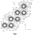
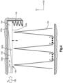
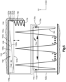
- an electrical coil assembly 102 can include an electrical coil 104 arranged in a folded position, so as to define a folded electrical coil. It will be understood that Fig. 1 represents a conceptual model, so the folded position and the arrangement of the electrical coil can vary as desired.
- the electrical coil 104 can include a substrate or film 106 and an electrical conductor 108 supported by the substrate 106.
- the substrate 106 can include a first or front face 106a and a second or back face 106b opposite the front face 106a.
- the electrical conductor 108 can be supported by the front face 106a, for instance only the front face 106a, of the substrate 106.
- the electrical coil 104 can define a plurality of segments 110.
- each segment 110 can include a respective portion of the front face 106a and a respective portion of the back face 106b opposite the front face 106a. Further, each segment can include a portion of the electrical conductor 108 arranged on the front face 106a of the substrate 106.
- the electrical coil can be arranged in the folded position so as to define a first plurality of folded edges 118 and a second plurality of folded edges 120 opposite the first plurality of folded edges 118 along a transverse or first direction D1.
- the electrical coil can be alternatively arranged (e.g., see Fig. 2 ) in a folded position so as to define folded edges in any position as desired.
- first plurality of folded edges 118 can include edges that are opposite each other, for instance opposite each other along the first direction D1.
- first plurality of folded edges 118 can include edges oriented, for example, perpendicularly to folded edges in the second plurality of folded edges 120.
- second plurality of folded edges 120 can include edges that are opposite each other, for instance opposite each other along the first direction D1.
- Figs. 1 and 2 depict examples of an electrical coil arrangement and shape to facilitate description of the disclosed subject matter, and are not intended to limit the scope of this disclosure.
- the electrical coil can be alternatively arranged (e.g., folded) and shaped in accordance with embodiments disclosed herein, and all such embodiments are contemplated as within the scope of the present disclosure.
- the electrical coil assembly 102 can be configured to be implanted into a patient's body.
- a system 200 is shown that is configured to track health of a patient over time.
- the system 200 comprises at least one implantable sensor 202 that is configured to be implanted into a patient's body 201.
- the electrical coil assembly 102 can be part of an anatomical implant of any suitable type such as (without limitation) a bone plate, an intramedullary nail, a bone anchor, a pedicles screw, a spine rod, an intervertebral implant, and so on.
- the system can also comprise an anatomical implant 204 configured to support the at least one sensor 202.
- the electrical coil assembly 102 can be configured to attach directly to an anatomical body of the patient without being supported by an anatomical implant.
- the electrical coil assembly 102 can be part of a device that is exposed to magnetic resonance imaging without being implanted.
- the electrical coil 104 can be configured as an antenna that converts the measurement value from an electrical signal into radio waves so as to transmit the measurement value wirelessly through the patient's skin to an external wireless communicator situated outside of the patient's body.
- the system can further comprise an external wireless communicator 206 configured to wirelessly receive data from the at least one sensor 202 through the skin of the patient when the external wireless communicator 206 is situated outside of the patient's body.
- the data can then be communicated to a computing device 208 that can be accessed by the patient or a medical professional.
- the sensor 202 comprises at least one sensing element 218 and a measurement device 214 in communication with the at least one sensing element 218. Together, the at least one sensing element 218 and measurement device 214 are configured to generate a measurement value when the sensor 202 is implanted in the patient's body.
- the anatomical property can be any suitable property for tracking the health of a patient such as (without limitation) strain, load, deflection, rotation, temperature, pressure, pH level, oxygen level, and so on.
- the sensor 202 can further comprise an internal wireless communicator in communication with the measurement device 214.
- the internal wireless communicator is configured to receive the measurement value from the measurement device and wirelessly communicate the measurement value through skin of the patient to the external wireless communicator 206 situated outside of the patient's body.
- the internal wireless communicator can be configured to communicate wirelessly using passive radio-frequency identification (RFID).
- RFID passive radio-frequency identification
- the internal wireless communicator can be configured to communicate using any other wireless communication technology suitable for communicating through the skin such as (without limitation) battery-assisted passive RFID, active RFID, blue tooth, and Wi-Fi.
- the internal wireless communicator can include a wireless transmitter 216 that receives the measurement value from the measurement device 214 and prepares the measurement value for wireless transmission.
- the wireless transmitter 216 can include processing such as (without limitation) one or more of (i) memory configured to store the measurement value, (ii) an digital-to-analog converter configured to convert the measurement value to analog format, (iii) a radio frequency (RF) modulator configured to modulate the measurement value, (iv) an error-correction encoder configured to encode the measurement value, and other processing consistent with the wireless technology employed by the sensor 202.
- the wireless transmitter 216 can further include a unique identifier or tag that can be used to distinguish the sensor 202 from other sensors.
- the wireless communicator can also include the electrical coil assembly 102, which can be configured to convert the measurement value from an electrical signal into radio waves so as to transmit the measurement value wirelessly through the patient's skin to the external wireless communicator 206 situated outside of the patient's body.
- the sensor 202 can comprise a power device 210 configured to supply power to the measurement device 214 and wireless communicator.
- the at least one sensing element 218, printed circuit board 212, and electrical coil assembly 102 can all be supported by the anatomical implant 204, which in turn can be attached to an anatomical body of the patient.
- the at least one sensing element 218, printed circuit board 212, and electrical coil assembly 102 can all be attached directly to the anatomical body of the patient.
- the external wireless communicator 206 can include the electrical coil assembly 102 and a wireless transmitter and receiver 220.
- the wireless transmitter and receiver 220 can be implemented separately or can be implemented as a transceiver.
- the external wireless communicator 206 can further include a computing device 222.
- the computing device 222 can be implemented separately from the external wireless communicator 216.
- each segment 110 of the electrical conductor 108 can include a first edge 112a and a second edge 112b opposite the first edge 112a along the transverse or first direction D1.
- Each segment 110 of the electrical conductor 108 can further include a third edge 112c and a fourth edge 112d opposite the third edge 112c along a lateral or second direction D2 that is substantially parallel to the first direction D1.
- Each segment 110 of the electrical conductor 108 can further include a plurality of edges 112e, for instance four edges 112e, that are angularly offset with respect to the first and second directions D1 and D2, respectively.
- the edges 112e can each extend from an end of the first edge 112a or the second edge 112b, to an end of the third edge 112c or the fourth edge 112d, such that each segment 110 defines an octagon, though it will be understood that the segments 110 can be alternatively shaped as desired.
- the front and back faces 106a and 106b can extend between the first and second edges 112a and 112b, and between the third and fourth edges 112c and 112d. In the unfolded position depicted in Fig. 2 , the front face 106a can be planar along the first and second directions D1 and D2, respectively.
- the illustrated folding pattern is presented to facilitate description of the disclosed subject matter, and is not intended to limit the scope of this disclosure.
- the segments 110 can define an octagon or can be alternatively shaped, for instance so as to define a triangle, square, or the like.
- the alternatively shaped segments may be used to implement configurations disclosed herein in addition to, or instead of, the illustrated segments, and all such configurations are contemplated as within the scope of the present disclosure.
- each segment 110 can be connected to at least one other segment 110.
- a first or front segment 110a in particular the first edge 112a of the front segment 110a, can define a first end of the electrical coil 104 in the unfolded position.
- a second or rear segment 110b in particular the third edge 112c of the rear segment 1 10b, can define a second end of the electrical coil 104 in the unfolded position.
- Each of the segments 110 can be connected to at least one other segment 110 so as to define the electrical coil 104.
- the front segment 110a is connected to one other segment 110
- the rear segment 110b is connected to one other segment 110
- the other segments 110 are connected to two other segments 110.
- each of the segments 110 excluding the front segment 110a and the rear segment 110b, can be connected to one segment 110 at either the first edge 112a or the second edge 112b, and one other segment 110 at either the third edge 112c or the fourth edge 112d, so as to define a step pattern depicted in Fig. 2 . It will be understood, however, that the segments 110 can be alternatively arranged as desired.
- each segment 110 can include an outer edge 112g that defines an octagon.
- Each segment 110 can define an inner edge 112f spaced from the outer edge 112g so as to define a hole 114 from the front face 106a of the substrate to the back face 106b of the substrate in each segment 110.
- the inner edge 112f is substantially circular, so as define the hole 114 that is substantially circular, but it will be understood that the inner edge 112f, and thus the hole 114, can be alternatively shaped as desired.
- the illustrated electrical coil configuration is presented to facilitate description of the disclosed subject matter, and is not intended to limit the scope of this disclosure.
- the holes can define a circle or can be alternatively shaped, for instance so as to define a triangle, square, or the like.
- the alternatively shaped holes may be used to implement configurations disclosed herein in addition to, or instead of, the illustrated electrical coils, and all such embodiments are contemplated as within the scope of the present disclosure.
- the electrical conductor 108 can include a plurality of conductive wires 116.
- Each of the conductive wires 116 can include a first or terminal end 116a arranged on one segment 110, and a second end 116b arranged on another segment 110 that is connected to the segment 110 on which the first end 116a is arranged.
- Each conductive wire 116 can extend about a center of the respective segment 110 in a spiral pattern from the first end 116a to the second end 116b, such that the first end 116a can be spaced from the second end 116b along the first and second directions D1 and D2, respectively.
- the conductive wire 116 supported by the front segment 110a and the third segment 110c can extend from the first end 116a, about the hole 114 defined by the first segment 110a in a spiral pattern, across the second edge 112b and the first edge 112a of the front segment 110a and the third segment 110c, respectively, and about the hole 114 defined by the third segment 110c to the second end 116b that is spaced from the first end 116a along the second direction D2.
- the first end 116a can be spaced from the fourth edge 112d a distance along the second direction D2 that is substantially equal to a distance that the second end 116b is spaced from the third edge 112c along the second direction D2.
- first and second ends 116a and 116b can each be spaced equally from a respective center point defined by the respective segments on which each of the ends 116a and 116b is arranged.
- the electrically wires 116 can define alternative patterns as desired.
- each of the ends 116a and 116b can be configured as contact pads to electrically connect to an electrical conductor, such as another conductive wire 116.
- each of the ends 116a-c can be configured to electrically connect to another segment 110, in accordance with any folded coil configuration desired.
- the electrical coil 104 in the unfolded position is folded into the folded position, such that the first end 116a of a given conductive wire 116 on a given segment 110 is electrically coupled to the second end 116b of the conductive wire 116 on a segment 110 adjacent to the given segment 110.
- the third segment 110c can be folded about an axis defined by the second edge 112a of the front segment 110a, such that the back face 106b of the front segment 110a contacts, or is adjacent to, the back face 106b of the third segment 110c.
- the third segment 110c can be folded about an axis defined by the fourth edge 112d of the fourth segment 1 10d, such that the second end 116b supported by the third segment 110c contacts, and is electrically coupled with, the first end 116a supported by the fourth segment 110d. Folding can proceed in this manner until each of the conductive wires 116 are electrically coupled with each other, such that the electrical conductor 108 defines a single continuous trace in the folded position. In particular, folding can proceed so as to define the electrical conductor 108 that extends from the first end 116a supported by the first segment 110a to a terminal end 116c of the conductor wire 116 supported by the rear segment 1 10b.
- each fold at the axis defined by one of the second edges 112a can expose the electrical conductor 108 at the fold so as to define a conductive edge.
- Each fold at the axis defined by one of the fourth edges 112d can expose no electrical conductor at the fold so as to define a nonconductive edge opposite the conductive edge.
- the first plurality of folded edges 118 can include conductive edges and the second plurality of folded edges 120 can include non-conductive edges. Further, the first plurality of folded edges 118 can define at least two exposed regions of the electrical coil 104.
- the first end 116a of the front segment 110a is not electrically coupled to another wire 116.
- the terminal end 116c can be configured so as to not be electrically coupled to one of the wires 116.
- each of the segments 110 can be spaced from each other along a longitudinal or third direction D3 that is substantially perpendicular to both the first and second directions D1 and D2, respectively.
- the electrical coil 104 arranged in the folded position can define the plurality of segments 110 along the third direction D3, such that each segment 110 is attached to at least one other segment 110 at a folded edge of the first or second plurality of folded edges 118 and 120, respectively.
- the electrical coil assembly 102 can further include a fuse element 150 that is spaced from the electrical coil 104 along the first direction D1.
- the fuse element 150 can be proximate to the first plurality of folded edges 118.
- the fuse element 150 can be spaced from the first plurality of folded edges 118 along the first direction D1.
- the fuse element 150 can be disposed closer to the first plurality of folded edges 118 as compared to the second plurality of folded edges 120.
- the front face 106a of the substrate 106 can face the fuse element 150 at the first plurality of folded edges 118, so as to expose the electrical conductor 108 to the fuse element 150 at the first plurality of folded edges 118.
- the back face 106b of the substrate 106 can face inward at the first plurality of folded edges 118, and the back face 106b face of the substrate 106 can face outward at the second plurality of folded edges 120.
- the electrical coil assembly 102 can further include a housing 103 that includes a first end 103a and a second end 103b opposite the first end along the first direction D1.
- the first end 103a can support the fuse element 150 and the second end can support the electrical coil 104.
- the housing 103 can further include a third end 103c and a fourth end 103d opposite the third end 103c along the third direction D3.
- the fuse element 150 can include an actuator 152, for instance a voltage actuator or a magnetic actuator, and an electrical fuse conductor 154 adjacent to the actuator 152.
- the electrical fuse conductor 154 is a conductive element that can consist of any electrically conductive material as desired
- the actuator 152 is a nonconductive element that can consist of any insulative material as desired.
- the electrical fuse conductor can consist of a housing and an electrically conductive trace supported by the housing.
- the electrical fuse conductor 154, and thus the electrical coil assembly 102 can be responsive to a magnetic field between approximately 1 Tesla and 5 Tesla, so as to urge the electrical fuse conductor to move toward the first plurality of folded edges 118.
- the electrical coil assembly can be responsive to strength levels of conventional MRI machines, for instance 1.5 Tesla and 3.0 Tesla.
- the actuator 152 can be arranged to move along the third direction D3 when the electrical coil assembly 102 is exposed to the magnetic field or the electrical potential induced in the coil by an MRI machine, so as to cause the electrical fuse conductor 154 to move toward the first plurality of folded edges 118.
- the actuator 152 can define a first or top surface 152a and a second or bottom surface 152b opposite the top surface 152a along the first direction D1.
- the electrical fuse conductor 154 can define a top surface 154a and a bottom surface 154b opposite the top surface 154a along the transverse direction.
- the bottom surface 152b of the actuator 152 can be configured to ride along the top surface 154a of the electrical fuse conductor 154 when the electrical coil assembly 102 is exposed to a magnetic field, which can be static or dynamic.
- the bottom surface 154b of the electrical fuse conductor 154 comprises electrically conductive material.
- only the bottom surface 154b of the electrical fuse conductor 154 comprises electrically conductive material.
- the electrical fuse conductor 154 is composed entirely of electrically conductive material, though it will be understood the composition of the electrical fuse conductor can vary as desired.
- the first end 103a of the housing 103 can define a first guide 105a and the top surface 152a of the actuator can define a second guide 105b that is complementary to the first guide 105a, such that the guides 105a and 105b can attach to each other so as to guide the actuator along the third direction D3.
- the fourth end 103d of housing 103 can define a first guide 107a and a rear surface 154c of the electrical fuse conductor 154 can define a second guide 107b that is complementary to the first guide 107a, such that the guides 107a and 107b can attach to each other so as to guide the electrical fuse conductor along the first direction D1.
- the rear surface 154c can ride along the fourth end 103d of the housing when the electrical coil assembly is exposed to an MRI machine.
- the fuse element 150 can include the electrical fuse conductor 154 proximate to the electrical coil 104, and the fuse element 150 can be movable from a first or disengaged position 160 whereby the electrical fuse conductor 154 is spaced from at least two exposed regions of the electrical coil, to a second or engaged position 162 whereby the electrical fuse conductor 154 is in electrical communication with the at least two exposed regions, such that current flows from a first one of the two exposed regions through the electrical fuse conductor 154 to a second one of the two exposed regions.
- the exposed regions can be arranged as desired.
- the front face 106a of the substrate can define one or more the exposed regions.
- the first plurality of folded edges 118 can define one or more of the exposed regions.
- the electrical coil assembly 102 can be responsive to a magnetic field between approximately 1 Tesla and 5 Tesla so as to urge the fuse element 150 to move from the disengaged position 160 to the engaged position 162.
- the fuse element 150 can be responsive to a magnetic resonance imaging machine so as to move from the disengaged position 160 to the engaged position 162, wherein the engaged position 162 defines a short circuit.
- the electrical fuse conductor 154 can be in mechanical contact with at least two exposed regions, for instance at least two of the first plurality of folded edges 118, of the electrical coil 104.
- the electrical fuse conductor 154 when the electrical fuse conductor 154 is in the engaged position 162, at least two of the first plurality of folded edges 118 are electrically coupled to one another via the electrical fuse conductor 154, for instance the bottom surface 154b of the electrical fuse conductor 154.
- the electrical coil assembly 102 can further include a bias element 156 configured to support the electrical fuse conductor 154, and thus the fuse element 150, in the disengaged position 160.
- the bias element 156 can include at least one spring element in contact with the electrical fuse conductor 154 so as to bias the electrical fuse conductor 154 along the first direction D1, though it will be understood that the fuse element 150 can be biased in an alternative direction or in alternative position as desired.
- the bias element 156 can be supported by a platform 176 that extends from the third end 103c of the housing 103.
- the bias element 156 can be supported by the housing 103, in particular the third end 103c of the housing 103.
- the bias element 156 can be alternatively configured to bias the fuse element 150 in the disengaged position 160 or the engaged position 162.
- the electrical fuse conductor 154 can be configured to be biased in the engaged position 162 in which the fuse element 150 is in contact with the electrical conductor of the electrical coil.
- the fuse element 150 can be movable from the engaged position 162 whereby the electrical fuse conductor 154 is in electrical communication with the electrical coil so as to electrically connect segments of the electrical coil with one another, to the disengaged position 160 whereby the electrical fuse conductor 154 is spaced from the electrical coil, such that the electrical coil defines a discontinuous electrical trace such that current does not flow through from the first end of the electrical coil to the second end of the electrical coil when the electrical fuse conductor is in the disengaged position 160.
- the electrical coil assembly 102 can be responsive to a magnetic field between approximately 1 Tesla and 5 Tesla so as to urge the fuse element 150 to move from the engaged position 162 to the disengaged position 160.
- the fuse element 150 can be responsive to a magnetic resonance imaging machine so as to move from the engaged position 162 to the disengaged position 160, wherein the disengaged position 160 defines an open circuit.
- the actuator 152 can include, or can be composed of, at least one magnet configured to move along any direction as desired, for instance along the third direction D3, when the electrical coil assembly 102 is exposed to a magnetic field 158, which can be a static magnetic field induced by magnetic resonance imaging.
- the electrical coil assembly 102 can include a plurality of actuators 152 (e.g., magnets), such that the actuators 152 are moveable in multiple directions, for instance the first direction D1, the second direction D2, and the third direction D3, to cause the electrical fuse conductor 154 to move toward (or away from) the electrical coil 104.
- the fuse element 150 can be moveable in response to magnetic fields having any direction.
- the electrical coil assembly 102 can further include a transfer member 170 having a first end 170a attached to a piezoelectric material 172.
- the transfer member can further include a second end 170b attached to the actuator 152.
- the piezoelectric material 172 can include a first terminal end 172a and a second terminal end 172b opposite the first terminal end 172a along the longitudinal direction.
- the first terminal end 172a can be attached to the third end 103c of the housing or can be otherwise prevented from moving or expanding toward the third end 103c.
- the second terminal end 172b can be attached to the first end 170a of the transfer member 170, such that, when the piezoelectric material expands, the second terminal end 172b of the piezoelectric material 172 and the electrical fuse conductor 154 do not move with respect to each other along the third direction D3.
- the piezoelectric material 172 can configured to expand when the electrical coil assembly 102 is exposed to an electrical potential (voltage) that is induced within the electrical coil by a changing magnetic field produced by an MRI machine.
- the piezoelectric material 172 can reside within the plurality of holes 114.
- the piezoelectric material 172 can reside outside of the holes 114.
- a ferromagnetic core can reside within some or all of the plurality of holes 114.
- the piezoelectric material 172 can extend through each of the plurality of segments 110.
- the piezoelectric material can include tourmaline, Rochelle sale, Quartz, or the like.
- the piezoelectric material 172 is electrically coupled to a first and second end of the electrical coil 104, such that when voltage is induced within the electrical coil 104 by magnetic resonance imaging, the piezoelectric material 172 expands, causing the electrical fuse conductor 154 to move, for instance toward the electrical coil 104.
- the piezoelectric material 172 can be connected to the first end 116a supported by the first segment 1 10a, and the terminal end 116c of the conductor wire 116 supported by the rear segment 1 10b.
- the first terminal end 172a of the piezoelectric material can be electrically coupled to the first end 116a of the first segment, and the second terminal end 172b of the piezoelectric material 172 can be electrically coupled to the terminal end 116c.
- the piezoelectric material 172 can be arranged to expand along the third direction D3 when exposed to magnetic resonance imaging.
- the piezoelectric material 172 is configured to expand along the third direction D3 only toward the fourth end 103d of the housing 103 when exposed to magnetic resonance imaging.
- the piezoelectric material 172 can about the third end 103c of the housing 103 such that the piezoelectric material 172 cannot expand toward the third end 103c.
- the electrical coil 104 can include the substrate 106 and an electrical conductor 108a defining a single continuous trace supported by the front face 106a of the substrate 106.
- the electrical coil 104 can be arranged in a folded position so as to define the first plurality of folded edges 118 and the second plurality of folded edges 120.
- the second plurality of folded edges 120 can include edges that are opposite folded edges in the first plurality of folded edges 118, for instance along the first direction D1.
- the electrical conductor 108a can define a first width 171 and a narrow location 173 having a second width 175 that is less than the first width 171, such that, when voltages or currents above a threshold are induced within the electrical coil 104, the electrical conductor 108a breaks at the narrow location 173 so as to no longer define the single continuous trace.
- the electrical conductor 108a can define one narrow location 173 or a plurality of narrow locations having the second width 175.
- adjacent segments 110 along the third direction D3 can define a pair of segments, and each pair of segments can support at least one narrow location 173 of the electrical conductor 108a.
- each pair of segments 110 supports only one narrow location 173 of the electrical conductor 108a.
- each segment 110 supports at least one, for instance one, narrow location 173 of the electrical conductor 108a.
- a method of manufacturing the electrical coil assembly 102 includes stamping an electrical conductor on a first face of a substrate so as to define an electrical coil.
- the method can further include folding the electrical coil into a folded position so as to define a first plurality of folded edges of the electrical coil and a second plurality of folded edges opposite the first plurality of folded edges along a transverse direction.
- the method can further include arranging a fuse element proximate to the first plurality of folded edges, such that the fuse element is spaced from the first plurality of folded edges along the transverse direction, and such that the first face of the substrate faces the fuse element at the first plurality of folded edges, so as to expose the electrical conductor to the fuse element at the first plurality of folded edges.
- the substrate defines a second face opposite the first face of the substrate
- the method of manufacturing the electrical coil assembly further includes stamping the electrical conductor only on the first face of the substrate.
- Folding the electrical coil into the folded position can include arranging the second face of the substrate to face inward at the first plurality of folded edges, and arranging the second face of the substrate to face outward at the second plurality of folded edges.
- the substrate can define a plurality of segments that each define an octagon, and folding the electrical coil into the folded position can include arranging the segments along a longitudinal direction substantially parallel to the transverse direction, such that each segment is attached to at least one other segment at a folded edge of the first or second plurality of folded edges.
- a method of manufacturing the electrical coil assembly can further include defining a plurality of holes in the substrate, and placing a piezoelectric material within the plurality of holes. Folding the electrical coil into the folded position can further include arranging the plurality of holes to align with one another along the longitudinal direction.
- stamping the electrical conductor includes stamping the electrical conductor about each hole so as to define a spiral pattern for each segment.
- the method of manufacturing the electrical coil assembly can further include arranging the fuse element by configuring the electrical fuse conductor of the fuse element to move toward the first plurality of folded edges when the electrical coil assembly is exposed to a magnetic field.
- Arranging the fuse element can further include configuring the actuator to move along the longitudinal direction when the electrical coil assembly is exposed to the magnetic field, according to the invention, so as to cause the electrical fuse conductor to move toward the first plurality of folded edges.
- the bottom surface of the actuator can be arranged to ride along the top surface of the electrical fuse conductor when the electrical coil assembly is exposed to a magnetic field or an electrical field.
- a method of manufacturing the electrical coil can further include selecting an electrically conductive material for the bottom surface of the electrical fuse conductor.
- a bias element can be placed such that the bias element supports the electrical fuse conductor in a disengaged position in which the electrical fuse conductor is out of contact with the electrical conductor.
- the bias element can be configured to allow the electrical fuse conductor to move from the disengaged position to an engaged position in which the electrical fuse conductor contacts the electrical conductor at the first plurality of folded edges when pressure is applied to the bias element along the transverse direction.
- placing the bias element includes placing at least one spring element in contact with the electrical fuse conductor so as to bias the electrical fuse conductor along the transverse direction.
- the method of manufacture can also include electrically coupling the actuator to the first and second end of the electrical coil, such that when voltage is induced within the electrical coil by magnetic resonance imaging, the piezoelectric material with the holes expands, which can cause the actuator to move.
- an electrical device or patient can be protected, using the electrical coil assembly, when the electrical device or patient is exposed to magnetic resonance imaging.
- the electrical device or patient can include an electrical coil comprising a substrate and an electrical conductor supported by a first face of the substrate.
- a method can include causing a fuse element including an electrical fuse conductor to move from a disengaged position in which the fuse element is spaced from at two exposed regions of the electrical coil to an engaged position in which the electrical fuse conductor is in electrical communication with the at least two exposed regions, such that current flows from a first one of the two exposed regions through the electrical fuse conductor to a second one of the at least two exposed regions.
- the method can further include causing the electrical fuse conductor of the fuse element to move toward the first plurality of folded edges along the transverse direction.
- the method can further include causing the actuator to move along a longitudinal direction that is substantially parallel to the transverse direction, so as to cause the electrical fuse conductor to move toward the first plurality of folded edges.
- the method can further include causing the bottom surface of the actuator to ride along the top surface of the electrical fuse conductor.
- Causing the fuse element to move from the disengaged position to the engaged position so as to define a short circuit can further include causing at least two of the first plurality of folded edges to be electrically coupled with one another via the fuse element.
- the method can further include returning the fuse element to the disengaged position from the engaged position, for example, when the electrical coil assembly is no longer exposed to an MRI machine.
- the method includes causing a piezoelectric material to expand, which can cause the electrical fuse conductor to move along the along the longitudinal direction.
- the fuse element is caused, for instance by an MRI machine, to move from an engaged position whereby the electrical fuse conductor is in electrical communication with the electrical coil so as to electrically connect segments of the electrical coil with one another, to the disengaged position whereby the electrical fuse conductor is spaced from the electrical coil, such that the electrical coil defines an open circuit.
- the electrical coil defines the open circuit
- the electrical coil includes a discontinuous electrical trace such that current does not flow through from the first end of the electrical coil to the terminal end of the electrical coil when the electrical fuse conductor is in the disengaged position.
- the electrical coil assembly can be responsive to a magnetic field between approximately 1 Tesla and 5 Tesla so as to urge the fuse element to move from the engaged position to the disengaged position.
- the fuse element can be responsive to a magnetic resonance imaging machine so as to move from the engaged position to the disengaged position.
Landscapes
- Health & Medical Sciences (AREA)
- Life Sciences & Earth Sciences (AREA)
- Engineering & Computer Science (AREA)
- Physics & Mathematics (AREA)
- Power Engineering (AREA)
- Medical Informatics (AREA)
- General Health & Medical Sciences (AREA)
- Veterinary Medicine (AREA)
- Biophysics (AREA)
- Pathology (AREA)
- Biomedical Technology (AREA)
- Heart & Thoracic Surgery (AREA)
- Public Health (AREA)
- Molecular Biology (AREA)
- Surgery (AREA)
- Animal Behavior & Ethology (AREA)
- Nuclear Medicine, Radiotherapy & Molecular Imaging (AREA)
- Orthopedic Medicine & Surgery (AREA)
- High Energy & Nuclear Physics (AREA)
- Radiology & Medical Imaging (AREA)
- Computer Networks & Wireless Communication (AREA)
- Manufacturing & Machinery (AREA)
- Microelectronics & Electronic Packaging (AREA)
- Magnetic Resonance Imaging Apparatus (AREA)
- Prostheses (AREA)
- Surgical Instruments (AREA)
- Air Bags (AREA)
Claims (15)
- Elektrische Spulenanordnung (102), umfassend:eine elektrische Spule (104) mit einem Substrat (106) und einem elektrischen Leiter (108), der vom Substrat (106) getragen wird, wobei die elektrische Spule (104) zumindest zwei freiliegende Bereiche definiert, undein Sicherungselement (150) mit einem elektrischen Sicherungsleiter (154) in der Nähe der elektrischen Spule (104), wobei das Sicherungselement (150) aus einer ausgerückten Position (160), wodurch der elektrische Sicherungsleiter (154) von den zumindest zwei freiliegenden Bereichen beabstandet ist, in eine eingerückte Position (162) bewegbar ist, wodurch der elektrische Sicherungsleiter (154) in elektrischer Verbindung mit den zumindest zwei freiliegenden Bereichen steht, sodass Strom von einem ersten der zwei freiliegenden Bereiche durch den elektrischen Sicherungsleiter (154) zu einem zweiten der zwei freiliegenden Bereiche fließt,wobei die elektrische Spulenanordnung (102) auf ein Magnetfeld zwischen etwa 1 Tesla und 5 Tesla anspricht, um das Sicherungselement (150) zum Bewegen von der ausgerückten Position (160) in die eingerückte Position (162) zu drängen, unddadurch gekennzeichnet, dass:das Sicherungselement (150) ferner einen Aktuator (152) angrenzend an den elektrischen Sicherungsleiter (154) umfasst, wobei der Aktuator (152) bewegbar ist, um zu bewirken, dass sich der elektrische Sicherungsleiter (154) in Richtung der zumindest zwei freiliegenden Bereiche bewegt.
- Elektrische Spulenanordnung (102) nach Anspruch 1, wobei das Sicherungselement (150) in die eingerückte Position (162) bewegbar ist, wodurch der elektrische Sicherungsleiter (154) in mechanischem Kontakt mit den zumindest zwei freiliegenden Bereichen steht.
- Elektrische Spulenanordnung (102) nach Anspruch 1, wobei das Sicherungselement (150) auf eine Magnetresonanz-Bildgebungsvorrichtung anspricht, um sich von der ausgerückten Position (160) in die eingerückte Position (162) zu bewegen.
- Elektrische Spulenanordnung (102) nach Anspruch 1, wobei der elektrische Leiter (108) von einer ersten Fläche des Substrats (106) getragen wird und die elektrische Spule (104) in einer zusammengefalteten Position angeordnet ist, um eine erste Vielzahl von Faltkanten (118) zu definieren, welche die zumindest zwei freiliegenden Bereiche definieren.
- Elektrische Spulenanordnung nach Anspruch 1, wobei der Aktuator (152) zum Bewegen entlang einer Längsrichtung konfiguriert ist, wenn die elektrische Spulenanordnung (102) dem Magnetfeld ausgesetzt ist, um zu bewirken, dass der elektrische Sicherungsleiter (154) sich entlang einer Querrichtung bewegt, die im Wesentlichen senkrecht zur Längsrichtung verläuft.
- Elektrische Spulenanordnung nach Anspruch 1, wobei der Aktuator (152) eine Oberseite (152a) und eine Unterseite (152b) gegenüber der Oberseite (152a) definiert, und der elektrische Sicherungsleiter (154) eine Oberseite (154a) und eine Unterseite (154b) gegenüber der Oberseite (154a) definiert, und die Unterseite (152b) des Aktuators (152) so konfiguriert ist, dass diese entlang der Oberseite (154a) des elektrischen Sicherungsleiters (154) entlanggleitet, wenn die elektrische Spulenanordnung (102) dem Magnetfeld ausgesetzt ist.
- Elektrische Spulenanordnung (102) nach Anspruch 6, wobei die Unterseite (154b) des elektrischen Sicherungsleiters (154) elektrisch leitendes Material umfasst.
- Elektrische Spulenanordnung (102) nach Anspruch 4, wobei, wenn sich der elektrische Sicherungsleiter (154) in der eingerückten Position (162) befindet, zumindest zwei der ersten Vielzahl von Faltkanten (118) über den elektrischen Sicherungsleiter (154) miteinander elektrisch verbunden sind.
- Elektrische Spulenanordnung (102) nach einem der vorhergehenden Ansprüche, wobei die elektrische Spulenanordnung (102) ferner ein Vorspannelement (156) umfasst, das den elektrischen Sicherungsleiter (154) in der ausgerückten Position (160) abstützt.
- Elektrische Spulenanordnung (102) nach Anspruch 9, wobei das Vorspannelement (156) zumindest ein Federelement in Kontakt mit dem elektrischen Sicherungsleiter (154) umfasst, um den elektrischen Sicherungsleiter (154) in die ausgerückte Position (160) vorzuspannen.
- Elektrische Spulenanordnung (102) nach Anspruch 6, wobei der Aktuator (152) einen Magneten umfasst, der entlang der Längsrichtung bewegbar ist, wenn die elektrische Spulenanordnung (102) dem Magnetfeld ausgesetzt ist.
- Elektrische Spulenanordnung (102) nach Anspruch 6, wobei der Aktuator (152) an einem piezoelektrischen Material befestigt ist, das so konfiguriert ist, dass es sich ausdehnt, wenn die elektrische Spulenanordnung (102) dem Magnetfeld ausgesetzt wird.
- Elektrische Spulenanordnung (102) nach Anspruch 12, wobei das piezoelektrische Material mit einem ersten und einem zweiten Ende der elektrischen Spule (104) elektrisch verbunden ist, sodass, wenn eine Spannung im Innern der elektrischen Spule (104) durch das Magnetfeld induziert wird, sich das piezoelektrische Material in Längsrichtung ausdehnt.
- Verfahren zum Herstellen einer elektrischen Spulenanordnung (102) nach Anspruch 1, wobei das Verfahren umfasst:Stanzen eines elektrischen Leiters (108) auf einer ersten Fläche eines Substrats (106), um eine elektrische Spule (102) zu definieren;Falten der elektrischen Spule (102) in eine gefaltete Position, um eine erste Vielzahl von Faltkanten (118) der elektrischen Spule (102) zu definieren; undAnordnen eines Sicherungselements (150) in der Nähe der ersten Vielzahl von Faltkanten (118), sodass das Sicherungselement (150) von der ersten Vielzahl von Faltkanten (118) entlang der Querrichtung beabstandet ist, und sodass die erste Fläche des Substrats (106) dem Sicherungselement (150) an der ersten Vielzahl von Faltkanten (118) zugewandt ist, um den elektrischen Leiter (108) an der ersten Vielzahl von Faltkanten (118) vom Sicherungselement (150) freizulegen.
- Verfahren nach Anspruch 14, wobei das Substrat (106) eine zweite Fläche gegenüber der ersten Fläche des Substrats (106) definiert, und Stanzen des elektrischen Leiters (108) ferner ein Stanzen des elektrischen Leiters (108) nur auf der ersten Fläche des Substrats (106) umfasst.
Applications Claiming Priority (2)
| Application Number | Priority Date | Filing Date | Title |
|---|---|---|---|
| US201762541985P | 2017-08-07 | 2017-08-07 | |
| PCT/US2018/044918 WO2019032358A1 (en) | 2017-08-07 | 2018-08-02 | MOLDED SECURE REINFORCED SPOOL ASSEMBLY |
Publications (2)
| Publication Number | Publication Date |
|---|---|
| EP3664708A1 EP3664708A1 (de) | 2020-06-17 |
| EP3664708B1 true EP3664708B1 (de) | 2023-04-12 |
Family
ID=63209715
Family Applications (1)
| Application Number | Title | Priority Date | Filing Date |
|---|---|---|---|
| EP18755649.3A Active EP3664708B1 (de) | 2017-08-07 | 2018-08-02 | Gefaltete mrt-sichere spulenanordnung |
Country Status (7)
| Country | Link |
|---|---|
| US (1) | US11322299B2 (de) |
| EP (1) | EP3664708B1 (de) |
| JP (1) | JP7258848B2 (de) |
| CN (1) | CN110996788B (de) |
| AU (1) | AU2018313692B2 (de) |
| CA (1) | CA3070216A1 (de) |
| WO (1) | WO2019032358A1 (de) |
Families Citing this family (3)
| Publication number | Priority date | Publication date | Assignee | Title |
|---|---|---|---|---|
| CN117034997A (zh) * | 2017-10-24 | 2023-11-10 | 艾利丹尼森零售信息服务公司 | 折叠时形成用于rfid标签的线圈的平面导电器件 |
| EP4203796A4 (de) * | 2020-08-31 | 2024-09-25 | GE Precision Healthcare LLC | Wärmeverwaltungssystem für computertomografie und verfahren zum betrieb dieses systems |
| JP7447863B2 (ja) * | 2021-04-26 | 2024-03-12 | 株式会社デンソー | 非接触給電用のコイルアッセンブリーおよび給電システム |
Family Cites Families (33)
| Publication number | Priority date | Publication date | Assignee | Title |
|---|---|---|---|---|
| US3123692A (en) * | 1964-03-03 | Fused switch | ||
| US2834855A (en) * | 1956-04-18 | 1958-05-13 | Gen Electric | Load break device |
| JPS4986311U (de) * | 1972-11-15 | 1974-07-26 | ||
| JPS5841694Y2 (ja) * | 1979-03-09 | 1983-09-20 | 富士通株式会社 | 密封形スイツチ |
| US4292616A (en) * | 1980-04-04 | 1981-09-29 | Andersen James H | Combined toggle switch and front access fuse holder |
| DE3133094C2 (de) * | 1981-08-21 | 1986-11-13 | Lindner Gmbh, Fabrik Elektrischer Lampen Und Apparate, 8600 Bamberg | Schmelzsicherungslastschalter |
| JPS5841946U (ja) * | 1981-09-14 | 1983-03-19 | 株式会社ゼネラルリサ−チオブエレクトロニツクス | スライド・スイツチ |
| JPS62114417U (de) * | 1986-01-09 | 1987-07-21 | ||
| FR2625604B1 (fr) | 1988-01-04 | 1990-05-04 | Vincent De Araujo Manuel | Dispositif de protection a fusible |
| JP2820703B2 (ja) * | 1989-01-25 | 1998-11-05 | 株式会社オリエント | 温度電流感知器 |
| JPH02205309A (ja) * | 1989-02-03 | 1990-08-15 | Murata Mfg Co Ltd | インダクタ |
| JP3017950B2 (ja) * | 1996-09-09 | 2000-03-13 | 東洋システム株式会社 | 電流・温度複合ヒューズ |
| US8244370B2 (en) * | 2001-04-13 | 2012-08-14 | Greatbatch Ltd. | Band stop filter employing a capacitor and an inductor tank circuit to enhance MRI compatibility of active medical devices |
| GB0027007D0 (en) * | 2000-11-04 | 2000-12-20 | Profec Technologies Oy | Inductive components |
| GB2373109B (en) * | 2001-02-13 | 2004-09-15 | Cooper | Full range high voltage current limiting fuse |
| US7570148B2 (en) | 2002-01-10 | 2009-08-04 | Cooper Technologies Company | Low resistance polymer matrix fuse apparatus and method |
| US7362889B2 (en) * | 2002-05-10 | 2008-04-22 | Massachusetts Institute Of Technology | Elastomeric actuator devices for magnetic resonance imaging |
| US7242981B2 (en) * | 2003-06-30 | 2007-07-10 | Codman Neuro Sciences Sárl | System and method for controlling an implantable medical device subject to magnetic field or radio frequency exposure |
| DE10334069A1 (de) * | 2003-07-25 | 2005-03-03 | Siemens Ag | Sicherungsbehaftetes Schaltschutzgerät |
| JP2007508706A (ja) | 2003-10-17 | 2007-04-05 | コーニンクレッカ フィリップス エレクトロニクス エヌ ヴィ | ヒューズを含むプリント回路基板 |
| CA2606824C (en) | 2005-05-04 | 2015-11-24 | Surgi-Vision, Inc. | Improved electrical lead for an electronic device such as an implantable device |
| US8258909B2 (en) | 2007-04-23 | 2012-09-04 | California Institute Of Technology | Foldable polymer-based coil structure and method for fabricating the same |
| JP5363020B2 (ja) * | 2008-04-07 | 2013-12-11 | オリンパスメディカルシステムズ株式会社 | カプセル型医療装置および医療システム |
| WO2009146492A1 (en) * | 2008-06-03 | 2009-12-10 | Cochlear Limited | Expandable structures |
| JP2011000273A (ja) * | 2009-06-18 | 2011-01-06 | Toshiba Corp | 磁性体接近防止装置および磁気共鳴診断装置 |
| EP2448479B1 (de) * | 2009-07-03 | 2013-11-13 | Imris Inc. | Rf-spule zur mr-abbildung, die nicht auf einem röntgenbild sichtbar ist |
| US8798767B2 (en) * | 2009-12-31 | 2014-08-05 | Cardiac Pacemakers, Inc. | MRI conditionally safe lead with multi-layer conductor |
| JP5465089B2 (ja) * | 2010-05-31 | 2014-04-09 | キヤノン株式会社 | 脳機能計測用視覚刺激提示装置、機能的磁気共鳴画像装置、脳磁計、脳機能計測方法 |
| CN103430272B (zh) * | 2011-06-02 | 2015-12-02 | 富士通株式会社 | 电子器件及其制造方法、电子器件的驱动方法 |
| KR101343037B1 (ko) * | 2011-11-10 | 2013-12-18 | 삼성전자 주식회사 | 자기 공명 영상용 무선 고주파 코일, 그 코일의 전원 제어 방법 및 그 코일을 이용한 자기 공명 영상 장치 |
| US9443683B2 (en) | 2012-04-24 | 2016-09-13 | Commscope Technologies Llc | RF thermal fuse |
| US9263211B2 (en) * | 2013-08-08 | 2016-02-16 | Palle Kohring Weinreich | Electrical switch with built in fuse |
| DE102015200507A1 (de) * | 2015-01-15 | 2016-07-21 | Volkswagen Aktiengesellschaft | Schalt- und Schutzeinrichtung für Hochvolt-Bordnetze |
-
2018
- 2018-08-02 EP EP18755649.3A patent/EP3664708B1/de active Active
- 2018-08-02 CN CN201880051499.5A patent/CN110996788B/zh active Active
- 2018-08-02 CA CA3070216A patent/CA3070216A1/en active Pending
- 2018-08-02 US US16/052,685 patent/US11322299B2/en active Active
- 2018-08-02 JP JP2020506758A patent/JP7258848B2/ja active Active
- 2018-08-02 AU AU2018313692A patent/AU2018313692B2/en active Active
- 2018-08-02 WO PCT/US2018/044918 patent/WO2019032358A1/en not_active Ceased
Also Published As
| Publication number | Publication date |
|---|---|
| JP2020530207A (ja) | 2020-10-15 |
| JP7258848B2 (ja) | 2023-04-17 |
| WO2019032358A8 (en) | 2020-02-06 |
| BR112020001932A2 (pt) | 2020-07-28 |
| CA3070216A1 (en) | 2019-02-14 |
| US20190043663A1 (en) | 2019-02-07 |
| AU2018313692A1 (en) | 2020-01-30 |
| AU2018313692B2 (en) | 2023-06-01 |
| AU2018313692A8 (en) | 2020-04-16 |
| WO2019032358A1 (en) | 2019-02-14 |
| CN110996788A (zh) | 2020-04-10 |
| CN110996788B (zh) | 2023-05-16 |
| EP3664708A1 (de) | 2020-06-17 |
| US11322299B2 (en) | 2022-05-03 |
Similar Documents
| Publication | Publication Date | Title |
|---|---|---|
| EP3664708B1 (de) | Gefaltete mrt-sichere spulenanordnung | |
| EP1806756B1 (de) | Miniaturspulen auf Kernen mit Leiterplatte | |
| KR101296776B1 (ko) | 센서 리더기와 함께 사용하는 조절가능한 안테나를포함하는 손목 밴드 또는 다른 유형의 밴드 | |
| JP4885092B2 (ja) | ブースターアンテナコイル | |
| CN207867013U (zh) | 局部线圈矩阵和带有局部线圈矩阵的磁共振断层成像设备 | |
| JP5429182B2 (ja) | 無線icデバイス | |
| WO1992000635A1 (en) | A data transmission equipment | |
| CN103442634A (zh) | 用于磁感应阻抗测量装置的平面线圈布置 | |
| CN106129592B (zh) | 用于无线通信的天线 | |
| WO2005000391A1 (en) | Inductive link for a medical implant | |
| Tang | A low-operating-voltage wireless intermediate-range scheme for energy and signal transmission by magnetic coupling for implantable devices | |
| JP4358242B2 (ja) | ブースターアンテナコイル | |
| JP3617965B2 (ja) | 無線カード | |
| US20170373389A1 (en) | Antenna apparatus and rfid system | |
| EP4118578B1 (de) | Elektromagnetische koppleranordnung | |
| WO2001084667A1 (en) | Card comprising an antenna | |
| BR112020001932B1 (pt) | Conjunto de bobina elétrica | |
| KR20170072761A (ko) | 코일 장치 및 이 장치를 포함하는 기기 | |
| US20190072626A1 (en) | Array coil | |
| JP6277685B2 (ja) | 通信端末装置 | |
| DE102014118038B4 (de) | Induktives Element zum Induzieren einer Spannung in einem elektrisch leitenden Bauteil und Verfahren für ein induktives Element | |
| KR101382355B1 (ko) | 전자기 유도방식의 무선전력 전송 시스템 | |
| WO2020217219A1 (en) | Method of load modulation, antenna system and chip for load modulation on the side of picc device | |
| KR100924427B1 (ko) | 안테나, 및 rfid 태그 | |
| JP2008178447A (ja) | 生体内装置 |
Legal Events
| Date | Code | Title | Description |
|---|---|---|---|
| STAA | Information on the status of an ep patent application or granted ep patent |
Free format text: STATUS: UNKNOWN |
|
| STAA | Information on the status of an ep patent application or granted ep patent |
Free format text: STATUS: THE INTERNATIONAL PUBLICATION HAS BEEN MADE |
|
| PUAI | Public reference made under article 153(3) epc to a published international application that has entered the european phase |
Free format text: ORIGINAL CODE: 0009012 |
|
| STAA | Information on the status of an ep patent application or granted ep patent |
Free format text: STATUS: REQUEST FOR EXAMINATION WAS MADE |
|
| 17P | Request for examination filed |
Effective date: 20200116 |
|
| AK | Designated contracting states |
Kind code of ref document: A1 Designated state(s): AL AT BE BG CH CY CZ DE DK EE ES FI FR GB GR HR HU IE IS IT LI LT LU LV MC MK MT NL NO PL PT RO RS SE SI SK SM TR |
|
| AX | Request for extension of the european patent |
Extension state: BA ME |
|
| DAV | Request for validation of the european patent (deleted) | ||
| DAX | Request for extension of the european patent (deleted) | ||
| GRAP | Despatch of communication of intention to grant a patent |
Free format text: ORIGINAL CODE: EPIDOSNIGR1 |
|
| STAA | Information on the status of an ep patent application or granted ep patent |
Free format text: STATUS: GRANT OF PATENT IS INTENDED |
|
| INTG | Intention to grant announced |
Effective date: 20221121 |
|
| GRAS | Grant fee paid |
Free format text: ORIGINAL CODE: EPIDOSNIGR3 |
|
| GRAA | (expected) grant |
Free format text: ORIGINAL CODE: 0009210 |
|
| STAA | Information on the status of an ep patent application or granted ep patent |
Free format text: STATUS: THE PATENT HAS BEEN GRANTED |
|
| AK | Designated contracting states |
Kind code of ref document: B1 Designated state(s): AL AT BE BG CH CY CZ DE DK EE ES FI FR GB GR HR HU IE IS IT LI LT LU LV MC MK MT NL NO PL PT RO RS SE SI SK SM TR |
|
| REG | Reference to a national code |
Ref country code: GB Ref legal event code: FG4D |
|
| REG | Reference to a national code |
Ref country code: CH Ref legal event code: EP |
|
| REG | Reference to a national code |
Ref country code: DE Ref legal event code: R096 Ref document number: 602018048329 Country of ref document: DE |
|
| REG | Reference to a national code |
Ref country code: IE Ref legal event code: FG4D |
|
| REG | Reference to a national code |
Ref country code: AT Ref legal event code: REF Ref document number: 1559357 Country of ref document: AT Kind code of ref document: T Effective date: 20230515 |
|
| REG | Reference to a national code |
Ref country code: LT Ref legal event code: MG9D |
|
| REG | Reference to a national code |
Ref country code: NL Ref legal event code: MP Effective date: 20230412 |
|
| REG | Reference to a national code |
Ref country code: AT Ref legal event code: MK05 Ref document number: 1559357 Country of ref document: AT Kind code of ref document: T Effective date: 20230412 |
|
| PG25 | Lapsed in a contracting state [announced via postgrant information from national office to epo] |
Ref country code: NL Free format text: LAPSE BECAUSE OF FAILURE TO SUBMIT A TRANSLATION OF THE DESCRIPTION OR TO PAY THE FEE WITHIN THE PRESCRIBED TIME-LIMIT Effective date: 20230412 |
|
| PG25 | Lapsed in a contracting state [announced via postgrant information from national office to epo] |
Ref country code: SE Free format text: LAPSE BECAUSE OF FAILURE TO SUBMIT A TRANSLATION OF THE DESCRIPTION OR TO PAY THE FEE WITHIN THE PRESCRIBED TIME-LIMIT Effective date: 20230412 Ref country code: PT Free format text: LAPSE BECAUSE OF FAILURE TO SUBMIT A TRANSLATION OF THE DESCRIPTION OR TO PAY THE FEE WITHIN THE PRESCRIBED TIME-LIMIT Effective date: 20230814 Ref country code: NO Free format text: LAPSE BECAUSE OF FAILURE TO SUBMIT A TRANSLATION OF THE DESCRIPTION OR TO PAY THE FEE WITHIN THE PRESCRIBED TIME-LIMIT Effective date: 20230712 Ref country code: ES Free format text: LAPSE BECAUSE OF FAILURE TO SUBMIT A TRANSLATION OF THE DESCRIPTION OR TO PAY THE FEE WITHIN THE PRESCRIBED TIME-LIMIT Effective date: 20230412 Ref country code: AT Free format text: LAPSE BECAUSE OF FAILURE TO SUBMIT A TRANSLATION OF THE DESCRIPTION OR TO PAY THE FEE WITHIN THE PRESCRIBED TIME-LIMIT Effective date: 20230412 |
|
| PG25 | Lapsed in a contracting state [announced via postgrant information from national office to epo] |
Ref country code: RS Free format text: LAPSE BECAUSE OF FAILURE TO SUBMIT A TRANSLATION OF THE DESCRIPTION OR TO PAY THE FEE WITHIN THE PRESCRIBED TIME-LIMIT Effective date: 20230412 Ref country code: PL Free format text: LAPSE BECAUSE OF FAILURE TO SUBMIT A TRANSLATION OF THE DESCRIPTION OR TO PAY THE FEE WITHIN THE PRESCRIBED TIME-LIMIT Effective date: 20230412 Ref country code: LV Free format text: LAPSE BECAUSE OF FAILURE TO SUBMIT A TRANSLATION OF THE DESCRIPTION OR TO PAY THE FEE WITHIN THE PRESCRIBED TIME-LIMIT Effective date: 20230412 Ref country code: LT Free format text: LAPSE BECAUSE OF FAILURE TO SUBMIT A TRANSLATION OF THE DESCRIPTION OR TO PAY THE FEE WITHIN THE PRESCRIBED TIME-LIMIT Effective date: 20230412 Ref country code: IS Free format text: LAPSE BECAUSE OF FAILURE TO SUBMIT A TRANSLATION OF THE DESCRIPTION OR TO PAY THE FEE WITHIN THE PRESCRIBED TIME-LIMIT Effective date: 20230812 Ref country code: HR Free format text: LAPSE BECAUSE OF FAILURE TO SUBMIT A TRANSLATION OF THE DESCRIPTION OR TO PAY THE FEE WITHIN THE PRESCRIBED TIME-LIMIT Effective date: 20230412 Ref country code: GR Free format text: LAPSE BECAUSE OF FAILURE TO SUBMIT A TRANSLATION OF THE DESCRIPTION OR TO PAY THE FEE WITHIN THE PRESCRIBED TIME-LIMIT Effective date: 20230713 Ref country code: AL Free format text: LAPSE BECAUSE OF FAILURE TO SUBMIT A TRANSLATION OF THE DESCRIPTION OR TO PAY THE FEE WITHIN THE PRESCRIBED TIME-LIMIT Effective date: 20230412 |
|
| PG25 | Lapsed in a contracting state [announced via postgrant information from national office to epo] |
Ref country code: FI Free format text: LAPSE BECAUSE OF FAILURE TO SUBMIT A TRANSLATION OF THE DESCRIPTION OR TO PAY THE FEE WITHIN THE PRESCRIBED TIME-LIMIT Effective date: 20230412 |
|
| REG | Reference to a national code |
Ref country code: DE Ref legal event code: R097 Ref document number: 602018048329 Country of ref document: DE |
|
| PG25 | Lapsed in a contracting state [announced via postgrant information from national office to epo] |
Ref country code: SK Free format text: LAPSE BECAUSE OF FAILURE TO SUBMIT A TRANSLATION OF THE DESCRIPTION OR TO PAY THE FEE WITHIN THE PRESCRIBED TIME-LIMIT Effective date: 20230412 |
|
| PG25 | Lapsed in a contracting state [announced via postgrant information from national office to epo] |
Ref country code: SM Free format text: LAPSE BECAUSE OF FAILURE TO SUBMIT A TRANSLATION OF THE DESCRIPTION OR TO PAY THE FEE WITHIN THE PRESCRIBED TIME-LIMIT Effective date: 20230412 Ref country code: SK Free format text: LAPSE BECAUSE OF FAILURE TO SUBMIT A TRANSLATION OF THE DESCRIPTION OR TO PAY THE FEE WITHIN THE PRESCRIBED TIME-LIMIT Effective date: 20230412 Ref country code: RO Free format text: LAPSE BECAUSE OF FAILURE TO SUBMIT A TRANSLATION OF THE DESCRIPTION OR TO PAY THE FEE WITHIN THE PRESCRIBED TIME-LIMIT Effective date: 20230412 Ref country code: EE Free format text: LAPSE BECAUSE OF FAILURE TO SUBMIT A TRANSLATION OF THE DESCRIPTION OR TO PAY THE FEE WITHIN THE PRESCRIBED TIME-LIMIT Effective date: 20230412 Ref country code: DK Free format text: LAPSE BECAUSE OF FAILURE TO SUBMIT A TRANSLATION OF THE DESCRIPTION OR TO PAY THE FEE WITHIN THE PRESCRIBED TIME-LIMIT Effective date: 20230412 Ref country code: CZ Free format text: LAPSE BECAUSE OF FAILURE TO SUBMIT A TRANSLATION OF THE DESCRIPTION OR TO PAY THE FEE WITHIN THE PRESCRIBED TIME-LIMIT Effective date: 20230412 |
|
| PLBE | No opposition filed within time limit |
Free format text: ORIGINAL CODE: 0009261 |
|
| STAA | Information on the status of an ep patent application or granted ep patent |
Free format text: STATUS: NO OPPOSITION FILED WITHIN TIME LIMIT |
|
| PG25 | Lapsed in a contracting state [announced via postgrant information from national office to epo] |
Ref country code: MC Free format text: LAPSE BECAUSE OF FAILURE TO SUBMIT A TRANSLATION OF THE DESCRIPTION OR TO PAY THE FEE WITHIN THE PRESCRIBED TIME-LIMIT Effective date: 20230412 |
|
| 26N | No opposition filed |
Effective date: 20240115 |
|
| REG | Reference to a national code |
Ref country code: CH Ref legal event code: PL |
|
| PG25 | Lapsed in a contracting state [announced via postgrant information from national office to epo] |
Ref country code: MC Free format text: LAPSE BECAUSE OF FAILURE TO SUBMIT A TRANSLATION OF THE DESCRIPTION OR TO PAY THE FEE WITHIN THE PRESCRIBED TIME-LIMIT Effective date: 20230412 |
|
| PG25 | Lapsed in a contracting state [announced via postgrant information from national office to epo] |
Ref country code: LU Free format text: LAPSE BECAUSE OF NON-PAYMENT OF DUE FEES Effective date: 20230802 |
|
| GBPC | Gb: european patent ceased through non-payment of renewal fee |
Effective date: 20230802 |
|
| PG25 | Lapsed in a contracting state [announced via postgrant information from national office to epo] |
Ref country code: LU Free format text: LAPSE BECAUSE OF NON-PAYMENT OF DUE FEES Effective date: 20230802 Ref country code: CH Free format text: LAPSE BECAUSE OF NON-PAYMENT OF DUE FEES Effective date: 20230831 |
|
| PG25 | Lapsed in a contracting state [announced via postgrant information from national office to epo] |
Ref country code: SI Free format text: LAPSE BECAUSE OF FAILURE TO SUBMIT A TRANSLATION OF THE DESCRIPTION OR TO PAY THE FEE WITHIN THE PRESCRIBED TIME-LIMIT Effective date: 20230412 |
|
| REG | Reference to a national code |
Ref country code: BE Ref legal event code: MM Effective date: 20230831 |
|
| REG | Reference to a national code |
Ref country code: IE Ref legal event code: MM4A |
|
| PG25 | Lapsed in a contracting state [announced via postgrant information from national office to epo] |
Ref country code: SI Free format text: LAPSE BECAUSE OF FAILURE TO SUBMIT A TRANSLATION OF THE DESCRIPTION OR TO PAY THE FEE WITHIN THE PRESCRIBED TIME-LIMIT Effective date: 20230412 Ref country code: IT Free format text: LAPSE BECAUSE OF FAILURE TO SUBMIT A TRANSLATION OF THE DESCRIPTION OR TO PAY THE FEE WITHIN THE PRESCRIBED TIME-LIMIT Effective date: 20230412 |
|
| PG25 | Lapsed in a contracting state [announced via postgrant information from national office to epo] |
Ref country code: IE Free format text: LAPSE BECAUSE OF NON-PAYMENT OF DUE FEES Effective date: 20230802 |
|
| PG25 | Lapsed in a contracting state [announced via postgrant information from national office to epo] |
Ref country code: GB Free format text: LAPSE BECAUSE OF NON-PAYMENT OF DUE FEES Effective date: 20230802 |
|
| PG25 | Lapsed in a contracting state [announced via postgrant information from national office to epo] |
Ref country code: IE Free format text: LAPSE BECAUSE OF NON-PAYMENT OF DUE FEES Effective date: 20230802 Ref country code: GB Free format text: LAPSE BECAUSE OF NON-PAYMENT OF DUE FEES Effective date: 20230802 Ref country code: FR Free format text: LAPSE BECAUSE OF NON-PAYMENT OF DUE FEES Effective date: 20230831 |
|
| PG25 | Lapsed in a contracting state [announced via postgrant information from national office to epo] |
Ref country code: BE Free format text: LAPSE BECAUSE OF NON-PAYMENT OF DUE FEES Effective date: 20230831 |
|
| PG25 | Lapsed in a contracting state [announced via postgrant information from national office to epo] |
Ref country code: BG Free format text: LAPSE BECAUSE OF FAILURE TO SUBMIT A TRANSLATION OF THE DESCRIPTION OR TO PAY THE FEE WITHIN THE PRESCRIBED TIME-LIMIT Effective date: 20230412 |
|
| PG25 | Lapsed in a contracting state [announced via postgrant information from national office to epo] |
Ref country code: BG Free format text: LAPSE BECAUSE OF FAILURE TO SUBMIT A TRANSLATION OF THE DESCRIPTION OR TO PAY THE FEE WITHIN THE PRESCRIBED TIME-LIMIT Effective date: 20230412 |
|
| PG25 | Lapsed in a contracting state [announced via postgrant information from national office to epo] |
Ref country code: CY Free format text: LAPSE BECAUSE OF FAILURE TO SUBMIT A TRANSLATION OF THE DESCRIPTION OR TO PAY THE FEE WITHIN THE PRESCRIBED TIME-LIMIT; INVALID AB INITIO Effective date: 20180802 |
|
| PG25 | Lapsed in a contracting state [announced via postgrant information from national office to epo] |
Ref country code: HU Free format text: LAPSE BECAUSE OF FAILURE TO SUBMIT A TRANSLATION OF THE DESCRIPTION OR TO PAY THE FEE WITHIN THE PRESCRIBED TIME-LIMIT; INVALID AB INITIO Effective date: 20180802 |
|
| PGFP | Annual fee paid to national office [announced via postgrant information from national office to epo] |
Ref country code: DE Payment date: 20250702 Year of fee payment: 8 |
|
| PG25 | Lapsed in a contracting state [announced via postgrant information from national office to epo] |
Ref country code: TR Free format text: LAPSE BECAUSE OF FAILURE TO SUBMIT A TRANSLATION OF THE DESCRIPTION OR TO PAY THE FEE WITHIN THE PRESCRIBED TIME-LIMIT Effective date: 20230412 |