EP3663877B1 - Machine tool control device, and machine tool - Google Patents
Machine tool control device, and machine tool Download PDFInfo
- Publication number
- EP3663877B1 EP3663877B1 EP18841160.7A EP18841160A EP3663877B1 EP 3663877 B1 EP3663877 B1 EP 3663877B1 EP 18841160 A EP18841160 A EP 18841160A EP 3663877 B1 EP3663877 B1 EP 3663877B1
- Authority
- EP
- European Patent Office
- Prior art keywords
- movement
- cutting tool
- spindle
- feed
- change point
- Prior art date
- Legal status (The legal status is an assumption and is not a legal conclusion. Google has not performed a legal analysis and makes no representation as to the accuracy of the status listed.)
- Active
Links
- 238000003754 machining Methods 0.000 claims description 48
- 238000010586 diagram Methods 0.000 description 21
- 230000000694 effects Effects 0.000 description 3
- 230000000737 periodic effect Effects 0.000 description 2
- 230000007423 decrease Effects 0.000 description 1
- 238000000034 method Methods 0.000 description 1
- 230000010355 oscillation Effects 0.000 description 1
- 230000002250 progressing effect Effects 0.000 description 1
Images


Classifications
-
- B—PERFORMING OPERATIONS; TRANSPORTING
- B23—MACHINE TOOLS; METAL-WORKING NOT OTHERWISE PROVIDED FOR
- B23Q—DETAILS, COMPONENTS, OR ACCESSORIES FOR MACHINE TOOLS, e.g. ARRANGEMENTS FOR COPYING OR CONTROLLING; MACHINE TOOLS IN GENERAL CHARACTERISED BY THE CONSTRUCTION OF PARTICULAR DETAILS OR COMPONENTS; COMBINATIONS OR ASSOCIATIONS OF METAL-WORKING MACHINES, NOT DIRECTED TO A PARTICULAR RESULT
- B23Q15/00—Automatic control or regulation of feed movement, cutting velocity or position of tool or work
- B23Q15/20—Automatic control or regulation of feed movement, cutting velocity or position of tool or work before or after the tool acts upon the workpiece
- B23Q15/22—Control or regulation of position of tool or workpiece
- B23Q15/225—Control or regulation of position of tool or workpiece in feed control, i.e. approaching of tool or work in successive decreasing velocity steps
-
- G—PHYSICS
- G05—CONTROLLING; REGULATING
- G05B—CONTROL OR REGULATING SYSTEMS IN GENERAL; FUNCTIONAL ELEMENTS OF SUCH SYSTEMS; MONITORING OR TESTING ARRANGEMENTS FOR SUCH SYSTEMS OR ELEMENTS
- G05B19/00—Programme-control systems
- G05B19/02—Programme-control systems electric
- G05B19/18—Numerical control [NC], i.e. automatically operating machines, in particular machine tools, e.g. in a manufacturing environment, so as to execute positioning, movement or co-ordinated operations by means of programme data in numerical form
- G05B19/416—Numerical control [NC], i.e. automatically operating machines, in particular machine tools, e.g. in a manufacturing environment, so as to execute positioning, movement or co-ordinated operations by means of programme data in numerical form characterised by control of velocity, acceleration or deceleration
- G05B19/4163—Adaptive control of feed or cutting velocity
-
- G—PHYSICS
- G05—CONTROLLING; REGULATING
- G05B—CONTROL OR REGULATING SYSTEMS IN GENERAL; FUNCTIONAL ELEMENTS OF SUCH SYSTEMS; MONITORING OR TESTING ARRANGEMENTS FOR SUCH SYSTEMS OR ELEMENTS
- G05B19/00—Programme-control systems
- G05B19/02—Programme-control systems electric
- G05B19/18—Numerical control [NC], i.e. automatically operating machines, in particular machine tools, e.g. in a manufacturing environment, so as to execute positioning, movement or co-ordinated operations by means of programme data in numerical form
- G05B19/4093—Numerical control [NC], i.e. automatically operating machines, in particular machine tools, e.g. in a manufacturing environment, so as to execute positioning, movement or co-ordinated operations by means of programme data in numerical form characterised by part programming, e.g. entry of geometrical information as taken from a technical drawing, combining this with machining and material information to obtain control information, named part programme, for the NC machine
-
- B—PERFORMING OPERATIONS; TRANSPORTING
- B23—MACHINE TOOLS; METAL-WORKING NOT OTHERWISE PROVIDED FOR
- B23B—TURNING; BORING
- B23B1/00—Methods for turning or working essentially requiring the use of turning-machines; Use of auxiliary equipment in connection with such methods
-
- B—PERFORMING OPERATIONS; TRANSPORTING
- B23—MACHINE TOOLS; METAL-WORKING NOT OTHERWISE PROVIDED FOR
- B23Q—DETAILS, COMPONENTS, OR ACCESSORIES FOR MACHINE TOOLS, e.g. ARRANGEMENTS FOR COPYING OR CONTROLLING; MACHINE TOOLS IN GENERAL CHARACTERISED BY THE CONSTRUCTION OF PARTICULAR DETAILS OR COMPONENTS; COMBINATIONS OR ASSOCIATIONS OF METAL-WORKING MACHINES, NOT DIRECTED TO A PARTICULAR RESULT
- B23Q15/00—Automatic control or regulation of feed movement, cutting velocity or position of tool or work
- B23Q15/007—Automatic control or regulation of feed movement, cutting velocity or position of tool or work while the tool acts upon the workpiece
- B23Q15/013—Control or regulation of feed movement
-
- G—PHYSICS
- G05—CONTROLLING; REGULATING
- G05B—CONTROL OR REGULATING SYSTEMS IN GENERAL; FUNCTIONAL ELEMENTS OF SUCH SYSTEMS; MONITORING OR TESTING ARRANGEMENTS FOR SUCH SYSTEMS OR ELEMENTS
- G05B19/00—Programme-control systems
- G05B19/02—Programme-control systems electric
- G05B19/18—Numerical control [NC], i.e. automatically operating machines, in particular machine tools, e.g. in a manufacturing environment, so as to execute positioning, movement or co-ordinated operations by means of programme data in numerical form
- G05B19/19—Numerical control [NC], i.e. automatically operating machines, in particular machine tools, e.g. in a manufacturing environment, so as to execute positioning, movement or co-ordinated operations by means of programme data in numerical form characterised by positioning or contouring control systems, e.g. to control position from one programmed point to another or to control movement along a programmed continuous path
-
- G—PHYSICS
- G05—CONTROLLING; REGULATING
- G05B—CONTROL OR REGULATING SYSTEMS IN GENERAL; FUNCTIONAL ELEMENTS OF SUCH SYSTEMS; MONITORING OR TESTING ARRANGEMENTS FOR SUCH SYSTEMS OR ELEMENTS
- G05B2219/00—Program-control systems
- G05B2219/30—Nc systems
- G05B2219/36—Nc in input of data, input key till input tape
- G05B2219/36204—Lathe, turning
-
- G—PHYSICS
- G05—CONTROLLING; REGULATING
- G05B—CONTROL OR REGULATING SYSTEMS IN GENERAL; FUNCTIONAL ELEMENTS OF SUCH SYSTEMS; MONITORING OR TESTING ARRANGEMENTS FOR SUCH SYSTEMS OR ELEMENTS
- G05B2219/00—Program-control systems
- G05B2219/30—Nc systems
- G05B2219/50—Machine tool, machine tool null till machine tool work handling
- G05B2219/50047—Positioning, indexing
-
- Y—GENERAL TAGGING OF NEW TECHNOLOGICAL DEVELOPMENTS; GENERAL TAGGING OF CROSS-SECTIONAL TECHNOLOGIES SPANNING OVER SEVERAL SECTIONS OF THE IPC; TECHNICAL SUBJECTS COVERED BY FORMER USPC CROSS-REFERENCE ART COLLECTIONS [XRACs] AND DIGESTS
- Y02—TECHNOLOGIES OR APPLICATIONS FOR MITIGATION OR ADAPTATION AGAINST CLIMATE CHANGE
- Y02P—CLIMATE CHANGE MITIGATION TECHNOLOGIES IN THE PRODUCTION OR PROCESSING OF GOODS
- Y02P90/00—Enabling technologies with a potential contribution to greenhouse gas [GHG] emissions mitigation
- Y02P90/02—Total factory control, e.g. smart factories, flexible manufacturing systems [FMS] or integrated manufacturing systems [IMS]
Definitions
- the present invention relates to a control device for a machine tool and a machine tool.
- Patent Literature 1 discloses a technique in vibration cutting that includes a feeding means for feeding a relatively rotating cutting tool and material, and the cutting tool is reciprocated relative to the material and chips can be segmented in cutting the material by combining a forward feed movement in the machining direction, in which the cutting tool machines the material, and a return movement in the counter-machining direction different from the machining direction.
- US2009/0107308 A1 discloses a cutting tool which superimposes an oscillation in the feed direction on the toolpath.
- Patent Literature 1 Japanese Patent Application Laid-Open No. 48-52083
- the present invention has been made in view of the above-described circumstances, and an object of the present invention is to provide a control device for a machine tool and a machine tool capable of easily performing cutting with vibration according to the amount of feed.
- the present invention is characterized a control device according to claim 1.
- the return movement setting means sets a pulse-like signal composed of a command for moving a cutting tool in the machining direction and a command for the return movement
- the forward feed setting means makes the cutting tool reach the change point by a combination movement of the movement in the machining direction based on the return movement setting means and the forward feed movement.
- the number of vibrations is one or more.
- the machine tool comprises any one of the above-described control devices for a machine tool.
- the present invention can obtain the following effects.
- a machine tool 100 includes a spindle 110, a cutting tool 130 such as a tool bit for machining a workpiece W, and a control device 180.
- a chuck 120 is provided at the end of the spindle 110, and the workpiece W is held by the spindle 110 via the chuck 120.
- the spindle 110 is rotatably supported by a spindle headstock 110A and rotationally driven by the power of a spindle motor (for example, a built-in motor) provided between the spindle headstock 110A and the spindle 110, for example.
- the spindle headstock 110A is installed on a Z-axis direction feeding mechanism 160.
- the Z-axis direction feeding mechanism 160 includes a base 161 integral with the bed, and a Z-axis direction guide rail 162 slidably supporting a Z-axis direction feeding table 163.
- a linear servomotor 165 When the Z-axis direction feeding table 163 is moved by the drive of a linear servomotor 165 along the illustrated Z-axis direction which coincides with the rotational axis direction of the workpiece W, the spindle headstock 110A moves in the Z-axis direction.
- the linear servomotor 165 has a mover 165a and a stator 165b.
- the mover 165a is provided on the Z-axis direction feeding table 163, and the stator 165b is provided on the base 161.
- the cutting tool 130 is mounted on a tool post 130A, and the tool post 130A is installed on an X-axis direction feeding mechanism 150.
- the X-axis direction feeding mechanism 150 includes a base 151 integral with the bed, and an X-axis direction guide rail 152 slidably supporting an X-axis direction feeding table 153.
- the linear servomotor 155 has a mover 155a and a stator 155b.
- the mover 155a is provided on the X-axis direction feeding table 153
- the stator 155b is provided on the base 151.
- a Y-axis direction feeding mechanism may be provided in the machine tool 100.
- the Y-axis direction is a direction orthogonal to the Z-axis direction and the X-axis direction shown in figures.
- the Y-axis direction feeding mechanism may have the same structure as the Z-axis direction feeding mechanism 160 or the X-axis direction feeding mechanism 150.
- the cutting tool 130 can be moved in the Y-axis direction in addition to the X-axis direction by a combination of the X-axis direction feeding mechanism 150 and the Y-axis direction feeding mechanism.
- the Z-axis direction feeding mechanism 160 has been described with examples using a linear servomotor, a known ball screw and servomotor may be used.
- the rotation of the spindle 110, the movement of the Z-axis direction feeding mechanism 160 and the like are controlled by the control device 180.
- the control device 180 includes a control section 181, a numerical value setting section 182, and a storage section 183, which are connected via a bus.
- the control section 181 is composed of a CPU or the like, loads various programs and data stored in, for example, a ROM of the storage section 183 into a RAM, and executes the program. Thereby, the operation of the machine tool 100 can be controlled on the basis of the program.
- the control section 181 has a motor control section 190 that is capable of controlling the rotation of the spindle 110 and the feed of the Z-axis direction feeding mechanism 160 and controls the operation of each motor.
- the control device 180 drives the spindle motor to rotate the workpiece W relative to the cutting tool 130, drives the Z-axis direction feeding mechanism 160 to move the workpiece W relative to the cutting tool 130 in the Z-axis direction, and drives the X-axis direction feeding mechanism 150 to move the cutting tool 130 relative to the workpiece W in the X-axis direction.
- the cutting tool 130 is moved relative to the workpiece W by relative movement between the cutting tool 130 and the workpiece W, and the cutting tool 130 is fed relative to the workpiece W in a predetermined feed direction so that the workpiece W can be machined by the cutting tool 130.
- the control device 180 moves the cutting tool 130 relative to the workpiece W along the feed direction by a predetermined amount of the forward movement toward the machining direction, which is the advancing direction of the machining feed, (this movement is referred to as forward movement), and then the Z-axis direction feeding mechanism 160 or the X-axis direction feeding mechanism 150 is driven to move (return) the cutting tool 130 by a predetermined amount of backward movement toward the counter-machining direction, which is the opposite direction to the machining direction.
- the control section 181 moves the Z-axis direction feeding mechanism 160 or the X-axis direction feeding mechanism 150 to move the spindle headstock 110A or the tool post 130A so that the cutting tool 130 reciprocates and vibrates.
- the workpiece W can be fed by a difference (an amount of progression) between the amount of the forward movement and the amount of the backward movement.
- a difference an amount of progression
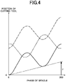
- the circumferential surface of the workpiece W is machined in a waveform according to the phase of the spindle 110.
- the number of reciprocal movements of the cutting tool 130 in one rotation of the workpiece W is D.
- FIG. 4 shows an example in which the number of vibrations D is 1.5 (times / r).
- a virtual line (dashed line) passing through the valley of the wavelike waveform is a feed straight line indicating the amount of feed, and a position where the phase of the spindle is 360 degrees in the feed straight line corresponds to the amount of feed F per one rotation of the workpiece W.
- the nth route of the cutting edge and the n+1th route of the cutting edge are reversed by 180 degrees.
- the air-cut period can be obtained if the nth route of the cutting edge and the n+1 route of the cutting edge do not coincide (are not in the same phase), and it is only need that the nth route of the cutting edge and the n+1th route of the cutting edge shift in the phase direction of the spindle.
- the period in which the route of the cutting edge of the n+1th rotation is included in the route of the cutting edge of the nth rotation decreases. If the route of the cutting edge of the n+1th rotation does not reach the route of the cutting edge of the nth rotation, the air-cut period will not be obtained.
- the control section 181 is configured to set the amplitude of the vibration waveform in proportion with the amount of feed F so that the air-cut period occurs.
- the number of rotations of the spindle and the amount of feed F are specified in advance for example by specifying them in a machining program.
- An amplitude ratio with respect to the amount of feed F is defined as an amplitude feed ratio Q.
- the control section 181 is configured to set the amplitude to Q*F, which is a multiplication of the amount of feed F and the amplitude feed ratio Q.
- the amplitude feed ratio Q can be specified as a value following Q (argument Q), for example, in a machining program.
- the number of vibrations D can also be specified as a value following D (argument D) in the machining program.
- the control section 181 has a return position calculation section 191, a forward feed setting section 192, and a return movement setting section 193 in order to move the cutting tool 130 relative to the workpiece W with vibrating the cutting tool 130.
- the control section 181 corresponds to the control means of the present invention
- the return position calculation section 191, the forward feed setting section 192, and the return movement setting section 193 correspond to the return position calculation means, the forward feed setting means, and the return movement setting means of the present invention respectively.
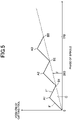
- a feed straight line is determined as shown in FIG. 5 .
- the feed straight line is referred to as a substantial feed line G.
- the substantial feed lined G is indicated by a dashed line in the graph in FIG. 5 .
- the phase of the spindle 110 is set as the horizontal axis direction and the position of the cutting tool 130 in the feed direction is set as the vertical axis.
- the cutting tool 130 is fed relative to the workpiece W so that the cutting tool 130 reaches the substantial feed line G at the time when one vibration is completed, switches from the backward movement to the forward movement, and vibrates 1.5 times during one rotation of the workpiece W, in other word vibrates 3 times during two rotation of the workpiece W .
- the return position calculation section 191 calculates a position on the substantial feed line G, at which the cutting tool 130 is located at the time when one vibration is completed, as the return position.
- FIG. 5 shows return positions for three vibrations as direction change points B1, B2 and B3 where the movement switches from the backward movement to the forward movement.
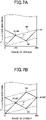
- the vibration waveform in FIG. 5 is expressed on a workpiece basis, and a return position of the cutting tool 130 at the time when one vibration is completed is on a substantial feed line G indicated by a dashed line in FIG. 6A .
- the phase of the spindle at the return position of the cutting tool 130 is obtained by multiplying the angle of one rotation of the workpiece W (360 degrees) by the inverse number (2/3) of the number of vibrations D.
- the change point B1 is at a position where the phase of the spindle is 240 degrees.
- each change point is on the substantial feed line G, and intervals between change points are determined by multiplying the angle of one rotation of the workpiece W by the inverse number of the number of vibrations D.
- the change point B2 on the substantial feed line G is at a position where the phase of the spindle is 480 degrees
- the change point B3 is at a position where the phase of the spindle is 720 degrees.
- the return position calculation section 191 can calculate each return position on the basis of the amount of feed F and the number of vibrations D as described above.
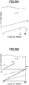
- the amplitude is set by multiplying the amount of feed F by the amplitude feed ratio Q. Therefore, the direction change point A1, at which the forward movement switches to the backward movement, is on a straight line (amplitude line QF) that is obtained by offsetting the actual feed line G by the amplitude Q*F.
- the phase of the spindle at the change point A1 is 120 degrees, which is a phase of the spindle obtained by multiplying 240 degrees, which is the phase of the spindle at the change point B1, by the inverse number (1/2) of the numerator of the inverse number (2/3) of the number of vibrations D. As shown in FIG.
- the change point A1 is set from the intersection of the amplitude line QF and the vertical line passing through 120 degrees of the phase of the spindle. Thereafter, the position of each change point A is on the amplitude line QF, and an interval between each change point A is determined by multiplying the angle between adjoining change points B by 1/2.
- the change point A2 is at an intermediate position (where the phase of the spindle is 360 degrees) from 240 degrees, which is the phase of the spindle of the change point B1, to 480 degrees, which is the phase of the spindle of the change point B2, and the change point A3 is at an intermediate position (where the phase of the spindle is 600 degrees) from 480 degrees, which is the phase of the spindle of the change point B2, to 720 degrees, which is the phase of the spindle of the change point B3.
- the change point A1 is determined using the amount of feed F, the amplitude feed ratio Q, and the number of vibrations D as parameters (change point setting values).
- the forward feed setting section 192 sets a straight line passing through the 0 degree of the phase of the spindle and the change point A1 as forward feed movement, and the control section 181 outputs a forward feed command for moving the cutting edge along the forward feed movement.
- the return movement setting section 193 is configured to output a movement command for moving the cutting tool 130 in the counter-machining direction as a pulse-like signal P at a predetermined interval.
- the direction change point B1 is at a position where the phase of the spindle is 240 degrees. Therefore, the pulse-like signal P has a downwardly convex waveform (indicated by a two-dot chain line in FIG. 6C ) opposite to the feed direction (vertical axis direction in the graph in FIG. 6C ) so that the cutting edge returns from the change point A1 to the change point B1.
- the pulse-like signal P is set as a signal output as a movement command for moving the cutting tool 130 in the counter-machining direction.
- a return movement in which the cutting edge periodically moves in the counter-machining direction, is performed.
- the height of the convex shape of the pulse-like signal P can be determined according to the distance between A1 and B1 viewed in the feed direction.
- the pulse-like signal P is set so that the cutting edge performs a backward movement F" that connects the change point A1 and the change point B1 as shown in FIG. 6D .
- the return movement setting section 193 is configured to include the pulse-like signal P.
- the pulse-like signal of the movement command for moving the cutting tool 130 in the counter-machining direction which is a periodic pulse-like command from the return movement setting section 193, has a period so that the backward movement F' is started from each change point A.
- the cutting edge performs the backward movement F" from the change point A1 to the change point B1 (a position where the phase of the spindle is 240 degrees) at the timing when the phase of the spindle is 120 degrees by the command of moving in the counter-machining direction (the downwardly convex portion of the pulse-like signal).
- the movement in the counter-machining direction is commanded at the timing when the phase of the spindle is 360 degrees, and a backward movement F" passing through the change point A2 and the change point B2 (a position where the phase of the spindle is 480 degrees) is performed.
- a backward movement F" passing through the change point A2 and the change point B2 (a position where the phase of the spindle is 480 degrees) is performed.
- the cutting tool 130 can be fed with the above-mentioned vibration by combining the forward feed movement and the return movement.
- the vibration of the cutting tool 130 can be automatically set according to the predetermined amount of feed F.
- the vibration of the cutting tool 130 can be automatically set according to the predetermined amount of feed F.
- the number of vibrations D can be set to be less than one.
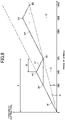
- FIG. 8 shows an example in which the number of vibrations D is 0.5 (times / r).
- the number of rotations of the spindle and the amount of feed F are also specified in advance for example by specifying them in a machining program.
- a substantial feed line G is determined (indicated by a dashed line in FIG. 8 ).
- the cutting tool 130 reaches the substantial feed line G when one vibration is completed, and switches from return movement to forward movement.
- the phase of the spindle 110 is set as the horizontal axis direction and the position in the feed direction of the cutting tool 130 is set as the vertical axis.
- the cutting tool 130 vibrates one time while the spindle 110 performs multiple rotation (two rotation in the present example). In the movement route of the cutting tool 130, the forward movement and the backward movement are performed at the same speed.
- the cutting tool 130 advances with forward movement in the first rotation of the spindle 110, switches from forward movement to backward movement at the position of 180 degrees in the last rotation of the multiple rotations of the spindle 110 (in the second rotation of the spindle 110 in the present example), and moves backward toward the substantial feed line G.
- the rotation amount of the spindle during the forward and backward movement of the cutting tool 130 is a rotation amount E of the spindle per vibration of the cutting tool. Further, the rotation amount of the spindle during the backward movement of the cutting tool 130 is a rotation amount R of the spindle in the return movement (backward movement) of the cutting tool 130.
- the rotation amount of the spindle during the backward movement of the cutting tool 130 is, in other words, the rotation amount of the spindle required from the time when the cutting tool 130 switches from the forward movement to the backward movement to the time when the cutting tool 130 reaches the substantial feed line G,
- the rotation amount of the spindle during the backward movement can be specified by a value following R (argument R), and the rotation amount of the spindle per vibration of the cutting tool can be specified in advance by a value following E (argument E).
- the rotation amount E of spindle per vibration of the cutting tool is the inverse number of the number of vibrations D, and is 2.0 (r / times) in the example in FIG. 8 .
- the return position calculation section 191 calculates a position of the phase of the spindle corresponding to the rotation amount E of the spindle on the substantial feed line G as a return position.
- FIG. 8 shows the return positions in two vibrations as direction change points B1 and B2 at which the backward movement changes to the forward movement.
- the vibration waveform in FIG. 8 is expressed on a workpiece basis, and the return position of the cutting tool 130 at the time when one vibration is completed is a position of the phase of the spindle on the substantial feed line G (indicated by a dashed chain line in FIG. 9A ) obtained by multiplying the angle of one rotation of the spindle (360 degrees) by the rotation amount E of the spindle.
- the change point B1 is at a position where the phase of the spindle is 720 degrees.
- each change point is a position on the substantial feed line G with an interval of an angle corresponding to two rotations of the workpiece W, and in the case of the present embodiment, the change point B2 on the substantial feed line G is in a position where the phase of the spindle is 1440 degrees.
- the return position calculation section 191 can calculate each return position on the bases of the rotation amount E of the spindle and the amount of feed F at the time when one vibration is completed.
- the rotation amount R of the spindle in the backward movement is 0.5 (rotation), thus a rotation of 180 degrees is required from the start to the end of the backward movement. Therefore, as shown in FIG. 9B , the direction change point A1, at which the forward movement switches to the backward movement, is a phase of the spindle (540 degrees), which is obtained by subtracting the angle corresponding to the rotation amount R of the spindle from the phase of the spindle at the return position (720 degrees).
- the forward feed setting section 192 sets a line C of 540 degrees of the phase of the spindle as the axis of symmetry, sets a point that is line symmetrical with respect to the change point B1 as the symmetry point B1', and sets the straight line passing through 0 degree of the phase of the spindle and the symmetry point B1' as the forward feed movement.
- the control section 181 outputs a forward feed command for moving the cutting edge along the forward feed movement.
- the change point A1 is at a position where the phase of the spindle is 540 degrees on a straight line passing through 0 degree of the phase of the spindle and the symmetry point B1'.
- the change point A1 is determined using the amount of feed F, the rotation amount R of the spindle in the backward movement and the rotation amount E of the spindle at the time when one vibration is completed as parameters (change point setting values).
- the forward feed setting section 192 sets the forward movement on the basis of the change point setting values.
- each change point A is at the position of each phase of the spindle, which is according to the rotation amount E of the spindle at the time when one vibration is completed.
- each symmetry point B' is a point that is line symmetrical with respect to each change point B with the axis of symmetry being the line of the phase of the spindle of each change point A corresponding to each change point B.
- the symmetry point B2' is at a position 360 degrees before 1440 degrees of the phase of the spindle of the change point B2.
- the symmetry point B2' is a position where the phase of the spindle is 1080 degrees.
- the change point A2 is at a position 180 degrees before 1440 degrees of the phase of the spindle of the change point B2.
- the change point A2 is a position where the phase of the spindle is 1260 degrees.
- the direction change point B1 is at a position where the phase of the spindle is 720 degrees.
- the pulse-like signal P is a periodic pulse-shaped command output from the return movement setting section 193 and is a movement command for moving the cutting edge in the counter-machining direction.
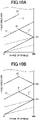
- the pulse-like signal P has a downwardly convex waveform (indicated by a two-dot chain line in FIG. 9C ) opposite to the feed direction (vertical axis direction in the graph in FIG. 9C ) so that the cutting edge returns from the change point A1 to the change point B1.
- the pulse-like signal P is set as a signal output as a movement command for moving the cutting edge in the counter-machining direction.
- the height of the convex shape of the pulse-like signal P can be determined according to the distance between A1 and B1 viewed in the feed direction.
- the pulse-like signal P is set so that the cutting edge performs a backward movement F" that connects the change point A1 and the change point B1 as shown in FIG. 9D .
- the return movement setting section 193 is configured to include the pulse-like signal P.
- the pulse-like signal has a period so that the backward movement F" is started from each change point A.
- the cutting edge performs the backward movement F" from the change point A1 to the change point B1 (a position where the phase of the spindle is 720 degrees) at the timing when the phase of the spindle is 540 degrees by the command of moving in the counter-machining direction (the downwardly convex portion of the pulse-like signal). If the backward movement F" intersects with the forward movement F' at the change point B1, the chips are segmented.
- movement in the counter-machining direction is commanded at the timing when the phase of the spindle is 1260 degrees, and as shown in FIG. 10B , a backward movement F' passing through the change point A2 and the change point B2 (a position where the phase of the spindle is 1440 degrees) is performed. If the backward movement F" intersects with the forward movement F' at the change point B2, the chip is segmented.
- the cutting tool 130 can be fed with the above-mentioned vibration by combining the forward feed movement and the return movement.
- the vibration of the cutting tool 130 can be automatically set according to the predetermined amount of feed F.
- the vibration of the cutting tool 130 can be automatically set according to the predetermined amount of feed F.
- the spindle 110 is rotated and fed in the Z-axis direction.
- the present invention is not limited to these examples. The same effect also can be obtained, for example in cases where the spindle 110 is rotated and the cutting tool 130 is fed in the Z-axis direction, the cutting tool 130 is rotated and the spindle 110 is fed in the Z-axis direction, the spindle 110 is fixed and the cutting tool 130 is rotated and fed in the Z-axis direction, and the like.
- the Z-axis direction feeding mechanism corresponds to the feeding means of the present invention.
- the rotation amount E of the spindle per vibration of the cutting tool in the second example may be set not only to an integral number of rotations such as two rotations and three rotations, but also to a number corresponding to a rotation angle exceeding one rotation (360 degrees).
- the pulse-like signal P of the return movement setting section 193 may be a signal or the like that repeats a command for moving the cutting tool 130 to the phase of the spindle of the change point A in the machining direction and a command for moving the cutting tool 130 from the phase of the spindle of the change point A in the counter-machining direction.
- the forward feed setting section 192 can set the forward feed movement so that the forward feed movement is a combination of a movement of the cutting edge in the machining direction based on the pulse-like signal P (the movement in the machining direction by the command for moving the cutting tool to the phase of the spindle of the change point A in the machining direction) and a movement in the machining direction by a predetermined forward feed command.
- the predetermined forward feed command can be, for example, a forward feed command for moving the cutting edge onto the substantial feed line G.
- FIG. 11A shows an example where the number of vibrations D is 0.5 (times / r).
- a substantial feed line G (indicated by a dashed line in the figure, which corresponds to the feed line of the cutting tool of the present invention) is determined. Further, on the basis of the rotation amount E of the spindle per vibration of the cutting tool and the amount of feed F, the return position (change point B1) on the substantial feed line G is calculated.
- the direction change point A1 at which the forward movement switches to the backward movement is at 540 degrees of the phase of the spindle.
- the line C of 540 degrees of the phase of the spindle is set as the axis of symmetry, and a symmetrical point B1', which is line symmetrical with respect to the change point B1, is set. Then, the straight line passing through 0 degree of the phase of the spindle and the symmetrical point B1' is set as forward feed movement.
- the predetermined forward feed command is a forward feed command for moving the cutting edge onto the substantial feed line G
- the pulse-like signal P is set to have an upwardly convex waveform (indicated by a two-dot chain line in FIG. 11C ) which is forwardly directed in the feed direction (vertical axis direction of the graph in FIG. 11B ) so as to return the cutting edge to the substantial feed line G after obtaining the positional difference C'.
- the forward feed setting section 192 sets the forward feed movement (indicated by F') by combining the movement in the machining direction by a command of the pulse-like signal P, which is for moving the cutting edge in the machining direction to 540 degrees of the phase of the spindle at the change point A1, and the movement in the machining direction determined by the amount of feed F (substantial feed line G).
- the pulse-like signal P has a period so that a straight line passing through 0 degree of the phase of the spindle and the symmetry point B1' starts from 0 degree of the phase of the spindle.
- the cutting edge performs the forward movement F' from 0 degree of the phase of the spindle to the change point A1 at the timing when the phase of the spindle is 0 degree, and starts the backward movement F" from the change point A1 on the forward movement F ' at the timing when the phase of the spindle is 540 degrees.
- the command for moving the cutting edge in the machining direction from the phase of the spindle of the change point B to the phase of the spindle of the change point A and the command for moving the cutting edge in the counter-machining direction from the phase of the spindle of the change point A to the phase of the spindle of the change point B are repeated by the pulse-like signal P.
- the forward feed command as a forward feed command for moving the cutting edge onto the substantial feed line G, because the substantial feed line G is the same as a line determined by the amount of feed F in general cutting without above-mentioned vibration (conventional cutting), the forward movement F' can be obtained by adding the pulse-like signal P to the conventional cutting.
- the pulse-like signal P can also be naturally applied to a case where the change point A1 is determined from the amount of feed F, the amplitude feed ratio Q, and the number of vibrations D.
Landscapes
- Engineering & Computer Science (AREA)
- Physics & Mathematics (AREA)
- Mechanical Engineering (AREA)
- Automation & Control Theory (AREA)
- Manufacturing & Machinery (AREA)
- General Physics & Mathematics (AREA)
- Human Computer Interaction (AREA)
- Geometry (AREA)
- Turning (AREA)
- Numerical Control (AREA)
- Automatic Control Of Machine Tools (AREA)
- Automatic Tool Replacement In Machine Tools (AREA)
- Finish Polishing, Edge Sharpening, And Grinding By Specific Grinding Devices (AREA)
Applications Claiming Priority (2)
| Application Number | Priority Date | Filing Date | Title |
|---|---|---|---|
| JP2017149111A JP6991774B2 (ja) | 2017-08-01 | 2017-08-01 | 工作機械の制御装置および工作機械 |
| PCT/JP2018/028117 WO2019026768A1 (ja) | 2017-08-01 | 2018-07-26 | 工作機械の制御装置および工作機械 |
Publications (3)
| Publication Number | Publication Date |
|---|---|
| EP3663877A1 EP3663877A1 (en) | 2020-06-10 |
| EP3663877A4 EP3663877A4 (en) | 2021-04-21 |
| EP3663877B1 true EP3663877B1 (en) | 2022-09-28 |
Family
ID=65233732
Family Applications (1)
| Application Number | Title | Priority Date | Filing Date |
|---|---|---|---|
| EP18841160.7A Active EP3663877B1 (en) | 2017-08-01 | 2018-07-26 | Machine tool control device, and machine tool |
Country Status (8)
| Country | Link |
|---|---|
| US (1) | US11446781B2 (ja) |
| EP (1) | EP3663877B1 (ja) |
| JP (2) | JP6991774B2 (ja) |
| KR (1) | KR102537867B1 (ja) |
| CN (1) | CN110945442B (ja) |
| ES (1) | ES2930359T3 (ja) |
| TW (1) | TWI760536B (ja) |
| WO (1) | WO2019026768A1 (ja) |
Families Citing this family (6)
| Publication number | Priority date | Publication date | Assignee | Title |
|---|---|---|---|---|
| JP6991774B2 (ja) * | 2017-08-01 | 2022-01-13 | シチズン時計株式会社 | 工作機械の制御装置および工作機械 |
| JP7264643B2 (ja) * | 2019-01-10 | 2023-04-25 | シチズン時計株式会社 | 工作機械の制御装置および工作機械 |
| JP7479947B2 (ja) | 2020-06-10 | 2024-05-09 | シチズン時計株式会社 | 工作機械の制御装置および工作機械 |
| WO2022025057A1 (ja) * | 2020-07-29 | 2022-02-03 | ファナック株式会社 | 工作機械の制御装置 |
| JP2022174914A (ja) | 2021-05-12 | 2022-11-25 | スター精密株式会社 | 工作機械 |
| WO2024069951A1 (ja) * | 2022-09-30 | 2024-04-04 | ファナック株式会社 | 工作機械の制御装置及び工作機械の表示装置 |
Family Cites Families (22)
| Publication number | Priority date | Publication date | Assignee | Title |
|---|---|---|---|---|
| JPS4852083A (ja) | 1971-11-04 | 1973-07-21 | ||
| AT326157B (de) | 1972-09-26 | 1975-11-25 | Kratzer Beat Dr Pharm | Verfahren zur herstellung eines matürlichen düngemittels und vorrichtung zur durchführung des verfahrens |
| JPH1015701A (ja) * | 1996-07-04 | 1998-01-20 | Mitsubishi Materials Corp | 振動バイトによる切削方法 |
| US8240234B2 (en) * | 2007-10-16 | 2012-08-14 | University Of North Carolina At Charlotte | Methods and systems for chip breaking in turning applications using CNC toolpaths |
| JP5594685B2 (ja) * | 2010-03-30 | 2014-09-24 | 国立大学法人名古屋大学 | 工具軌跡生成装置、工具軌跡算出方法および工具軌跡生成プログラム |
| JP5417392B2 (ja) * | 2011-07-29 | 2014-02-12 | 新日本工機株式会社 | 数値制御装置 |
| CN104995571B (zh) | 2013-02-12 | 2017-03-08 | 三菱电机株式会社 | 数控装置 |
| KR101560529B1 (ko) * | 2014-04-23 | 2015-10-14 | 미쓰비시덴키 가부시키가이샤 | 수치 제어 장치 |
| ES2680349T3 (es) | 2014-04-23 | 2018-09-06 | Mitsubishi Electric Corporation | Aparato de control numérico |
| EP4245443A1 (en) * | 2014-08-29 | 2023-09-20 | Citizen Watch Co., Ltd. | Machine tool and control apparatus for machine tool |
| JP5823082B1 (ja) | 2014-09-09 | 2015-11-25 | 三菱電機株式会社 | 数値制御装置 |
| ES2813968T3 (es) * | 2014-09-22 | 2021-03-25 | Citizen Watch Co Ltd | Máquina herramienta y aparato de conrol de la máquina herramienta |
| JP6709163B2 (ja) * | 2014-10-08 | 2020-06-10 | シチズン時計株式会社 | 工作機械及びこの工作機械の制御装置 |
| EP3225355B1 (en) * | 2014-11-26 | 2019-09-11 | Mitsubishi Electric Corporation | Numerical control apparatus |
| JP6517061B2 (ja) * | 2015-03-26 | 2019-05-22 | シチズン時計株式会社 | 工作機械及びこの工作機械の制御装置 |
| WO2016152768A1 (ja) * | 2015-03-26 | 2016-09-29 | シチズンホールディングス株式会社 | 工作機械及びこの工作機械の制御装置 |
| JP2016194860A (ja) * | 2015-04-01 | 2016-11-17 | 東芝機械株式会社 | 振動切削加工装置および振動切削加工方法 |
| EP3354402B1 (en) * | 2015-09-24 | 2024-04-17 | Citizen Watch Co., Ltd. | Machine tool control device, and machine tool equipped with said control device |
| TWI697380B (zh) * | 2015-09-24 | 2020-07-01 | 日商西鐵城時計股份有限公司 | 工具機的控制裝置以及具備該控制裝置的工具機 |
| JP6457432B2 (ja) * | 2016-05-16 | 2019-01-23 | ファナック株式会社 | 揺動切削を行う工作機械のサーボ制御装置、制御方法及びコンピュータプログラム |
| WO2018117203A1 (ja) | 2016-12-22 | 2018-06-28 | シチズン時計株式会社 | 工作機械およびその制御装置 |
| JP6991774B2 (ja) | 2017-08-01 | 2022-01-13 | シチズン時計株式会社 | 工作機械の制御装置および工作機械 |
-
2017
- 2017-08-01 JP JP2017149111A patent/JP6991774B2/ja active Active
-
2018
- 2018-07-26 KR KR1020207004127A patent/KR102537867B1/ko active IP Right Grant
- 2018-07-26 EP EP18841160.7A patent/EP3663877B1/en active Active
- 2018-07-26 TW TW107125931A patent/TWI760536B/zh active
- 2018-07-26 CN CN201880048133.2A patent/CN110945442B/zh active Active
- 2018-07-26 ES ES18841160T patent/ES2930359T3/es active Active
- 2018-07-26 WO PCT/JP2018/028117 patent/WO2019026768A1/ja unknown
- 2018-07-26 US US16/635,384 patent/US11446781B2/en active Active
- 2018-09-06 JP JP2018167329A patent/JP7161349B2/ja active Active
Also Published As
| Publication number | Publication date |
|---|---|
| US20200156200A1 (en) | 2020-05-21 |
| JP6991774B2 (ja) | 2022-01-13 |
| EP3663877A1 (en) | 2020-06-10 |
| JP2019028831A (ja) | 2019-02-21 |
| KR20200031130A (ko) | 2020-03-23 |
| TWI760536B (zh) | 2022-04-11 |
| US11446781B2 (en) | 2022-09-20 |
| ES2930359T3 (es) | 2022-12-09 |
| JP2020017249A (ja) | 2020-01-30 |
| JP7161349B2 (ja) | 2022-10-26 |
| CN110945442B (zh) | 2023-02-14 |
| WO2019026768A1 (ja) | 2019-02-07 |
| TW201910046A (zh) | 2019-03-16 |
| EP3663877A4 (en) | 2021-04-21 |
| CN110945442A (zh) | 2020-03-31 |
| KR102537867B1 (ko) | 2023-05-31 |
Similar Documents
| Publication | Publication Date | Title |
|---|---|---|
| EP3663877B1 (en) | Machine tool control device, and machine tool | |
| JP7304315B2 (ja) | 工作機械及びこの工作機械の制御装置 | |
| EP3851927A1 (en) | Control device for machine tool and machine tool | |
| EP3187290B1 (en) | Method for machining a workpiece by a machine tool | |
| JP6416217B2 (ja) | 工作機械の制御装置及びこの制御装置を備えた工作機械 | |
| TWI789382B (zh) | 工具機的控制裝置以及工具機 | |
| US20160011579A1 (en) | Numerical control device | |
| TWI765105B (zh) | 工作機械 | |
| KR101560529B1 (ko) | 수치 제어 장치 | |
| JP6875810B2 (ja) | 工作機械およびその制御装置 | |
| JP6517060B2 (ja) | 工作機械及びこの工作機械の制御装置 | |
| EP3696634B1 (en) | Machine tool | |
| JP2023141865A (ja) | 工作機械 |
Legal Events
| Date | Code | Title | Description |
|---|---|---|---|
| STAA | Information on the status of an ep patent application or granted ep patent |
Free format text: STATUS: THE INTERNATIONAL PUBLICATION HAS BEEN MADE |
|
| PUAI | Public reference made under article 153(3) epc to a published international application that has entered the european phase |
Free format text: ORIGINAL CODE: 0009012 |
|
| STAA | Information on the status of an ep patent application or granted ep patent |
Free format text: STATUS: REQUEST FOR EXAMINATION WAS MADE |
|
| 17P | Request for examination filed |
Effective date: 20200219 |
|
| AK | Designated contracting states |
Kind code of ref document: A1 Designated state(s): AL AT BE BG CH CY CZ DE DK EE ES FI FR GB GR HR HU IE IS IT LI LT LU LV MC MK MT NL NO PL PT RO RS SE SI SK SM TR |
|
| AX | Request for extension of the european patent |
Extension state: BA ME |
|
| DAV | Request for validation of the european patent (deleted) | ||
| DAX | Request for extension of the european patent (deleted) | ||
| A4 | Supplementary search report drawn up and despatched |
Effective date: 20210319 |
|
| RIC1 | Information provided on ipc code assigned before grant |
Ipc: G05B 19/4093 20060101AFI20210315BHEP Ipc: B23B 1/00 20060101ALI20210315BHEP Ipc: B23Q 15/013 20060101ALI20210315BHEP |
|
| RIN1 | Information on inventor provided before grant (corrected) |
Inventor name: NAKAYA, TAKAICHI Inventor name: SHINOHARA, HIROSHI |
|
| GRAP | Despatch of communication of intention to grant a patent |
Free format text: ORIGINAL CODE: EPIDOSNIGR1 |
|
| STAA | Information on the status of an ep patent application or granted ep patent |
Free format text: STATUS: GRANT OF PATENT IS INTENDED |
|
| RIC1 | Information provided on ipc code assigned before grant |
Ipc: B23Q 15/013 20060101ALI20220520BHEP Ipc: B23B 1/00 20060101ALI20220520BHEP Ipc: G05B 19/4093 20060101AFI20220520BHEP |
|
| INTG | Intention to grant announced |
Effective date: 20220623 |
|
| GRAS | Grant fee paid |
Free format text: ORIGINAL CODE: EPIDOSNIGR3 |
|
| GRAA | (expected) grant |
Free format text: ORIGINAL CODE: 0009210 |
|
| STAA | Information on the status of an ep patent application or granted ep patent |
Free format text: STATUS: THE PATENT HAS BEEN GRANTED |
|
| AK | Designated contracting states |
Kind code of ref document: B1 Designated state(s): AL AT BE BG CH CY CZ DE DK EE ES FI FR GB GR HR HU IE IS IT LI LT LU LV MC MK MT NL NO PL PT RO RS SE SI SK SM TR |
|
| REG | Reference to a national code |
Ref country code: GB Ref legal event code: FG4D |
|
| REG | Reference to a national code |
Ref country code: CH Ref legal event code: EP |
|
| REG | Reference to a national code |
Ref country code: AT Ref legal event code: REF Ref document number: 1521640 Country of ref document: AT Kind code of ref document: T Effective date: 20221015 |
|
| REG | Reference to a national code |
Ref country code: DE Ref legal event code: R096 Ref document number: 602018041233 Country of ref document: DE |
|
| REG | Reference to a national code |
Ref country code: IE Ref legal event code: FG4D |
|
| REG | Reference to a national code |
Ref country code: ES Ref legal event code: FG2A Ref document number: 2930359 Country of ref document: ES Kind code of ref document: T3 Effective date: 20221209 |
|
| REG | Reference to a national code |
Ref country code: LT Ref legal event code: MG9D |
|
| PG25 | Lapsed in a contracting state [announced via postgrant information from national office to epo] |
Ref country code: SE Free format text: LAPSE BECAUSE OF FAILURE TO SUBMIT A TRANSLATION OF THE DESCRIPTION OR TO PAY THE FEE WITHIN THE PRESCRIBED TIME-LIMIT Effective date: 20220928 Ref country code: RS Free format text: LAPSE BECAUSE OF FAILURE TO SUBMIT A TRANSLATION OF THE DESCRIPTION OR TO PAY THE FEE WITHIN THE PRESCRIBED TIME-LIMIT Effective date: 20220928 Ref country code: NO Free format text: LAPSE BECAUSE OF FAILURE TO SUBMIT A TRANSLATION OF THE DESCRIPTION OR TO PAY THE FEE WITHIN THE PRESCRIBED TIME-LIMIT Effective date: 20221228 Ref country code: LV Free format text: LAPSE BECAUSE OF FAILURE TO SUBMIT A TRANSLATION OF THE DESCRIPTION OR TO PAY THE FEE WITHIN THE PRESCRIBED TIME-LIMIT Effective date: 20220928 Ref country code: LT Free format text: LAPSE BECAUSE OF FAILURE TO SUBMIT A TRANSLATION OF THE DESCRIPTION OR TO PAY THE FEE WITHIN THE PRESCRIBED TIME-LIMIT Effective date: 20220928 Ref country code: FI Free format text: LAPSE BECAUSE OF FAILURE TO SUBMIT A TRANSLATION OF THE DESCRIPTION OR TO PAY THE FEE WITHIN THE PRESCRIBED TIME-LIMIT Effective date: 20220928 |
|
| REG | Reference to a national code |
Ref country code: NL Ref legal event code: MP Effective date: 20220928 |
|
| REG | Reference to a national code |
Ref country code: AT Ref legal event code: MK05 Ref document number: 1521640 Country of ref document: AT Kind code of ref document: T Effective date: 20220928 |
|
| PG25 | Lapsed in a contracting state [announced via postgrant information from national office to epo] |
Ref country code: HR Free format text: LAPSE BECAUSE OF FAILURE TO SUBMIT A TRANSLATION OF THE DESCRIPTION OR TO PAY THE FEE WITHIN THE PRESCRIBED TIME-LIMIT Effective date: 20220928 Ref country code: GR Free format text: LAPSE BECAUSE OF FAILURE TO SUBMIT A TRANSLATION OF THE DESCRIPTION OR TO PAY THE FEE WITHIN THE PRESCRIBED TIME-LIMIT Effective date: 20221229 |
|
| PG25 | Lapsed in a contracting state [announced via postgrant information from national office to epo] |
Ref country code: SM Free format text: LAPSE BECAUSE OF FAILURE TO SUBMIT A TRANSLATION OF THE DESCRIPTION OR TO PAY THE FEE WITHIN THE PRESCRIBED TIME-LIMIT Effective date: 20220928 Ref country code: RO Free format text: LAPSE BECAUSE OF FAILURE TO SUBMIT A TRANSLATION OF THE DESCRIPTION OR TO PAY THE FEE WITHIN THE PRESCRIBED TIME-LIMIT Effective date: 20220928 Ref country code: PT Free format text: LAPSE BECAUSE OF FAILURE TO SUBMIT A TRANSLATION OF THE DESCRIPTION OR TO PAY THE FEE WITHIN THE PRESCRIBED TIME-LIMIT Effective date: 20230130 Ref country code: CZ Free format text: LAPSE BECAUSE OF FAILURE TO SUBMIT A TRANSLATION OF THE DESCRIPTION OR TO PAY THE FEE WITHIN THE PRESCRIBED TIME-LIMIT Effective date: 20220928 Ref country code: AT Free format text: LAPSE BECAUSE OF FAILURE TO SUBMIT A TRANSLATION OF THE DESCRIPTION OR TO PAY THE FEE WITHIN THE PRESCRIBED TIME-LIMIT Effective date: 20220928 |
|
| PG25 | Lapsed in a contracting state [announced via postgrant information from national office to epo] |
Ref country code: SK Free format text: LAPSE BECAUSE OF FAILURE TO SUBMIT A TRANSLATION OF THE DESCRIPTION OR TO PAY THE FEE WITHIN THE PRESCRIBED TIME-LIMIT Effective date: 20220928 Ref country code: PL Free format text: LAPSE BECAUSE OF FAILURE TO SUBMIT A TRANSLATION OF THE DESCRIPTION OR TO PAY THE FEE WITHIN THE PRESCRIBED TIME-LIMIT Effective date: 20220928 Ref country code: IS Free format text: LAPSE BECAUSE OF FAILURE TO SUBMIT A TRANSLATION OF THE DESCRIPTION OR TO PAY THE FEE WITHIN THE PRESCRIBED TIME-LIMIT Effective date: 20230128 Ref country code: EE Free format text: LAPSE BECAUSE OF FAILURE TO SUBMIT A TRANSLATION OF THE DESCRIPTION OR TO PAY THE FEE WITHIN THE PRESCRIBED TIME-LIMIT Effective date: 20220928 |
|
| REG | Reference to a national code |
Ref country code: DE Ref legal event code: R097 Ref document number: 602018041233 Country of ref document: DE |
|
| PG25 | Lapsed in a contracting state [announced via postgrant information from national office to epo] |
Ref country code: NL Free format text: LAPSE BECAUSE OF FAILURE TO SUBMIT A TRANSLATION OF THE DESCRIPTION OR TO PAY THE FEE WITHIN THE PRESCRIBED TIME-LIMIT Effective date: 20220928 Ref country code: AL Free format text: LAPSE BECAUSE OF FAILURE TO SUBMIT A TRANSLATION OF THE DESCRIPTION OR TO PAY THE FEE WITHIN THE PRESCRIBED TIME-LIMIT Effective date: 20220928 |
|
| PG25 | Lapsed in a contracting state [announced via postgrant information from national office to epo] |
Ref country code: DK Free format text: LAPSE BECAUSE OF FAILURE TO SUBMIT A TRANSLATION OF THE DESCRIPTION OR TO PAY THE FEE WITHIN THE PRESCRIBED TIME-LIMIT Effective date: 20220928 |
|
| PGFP | Annual fee paid to national office [announced via postgrant information from national office to epo] |
Ref country code: IT Payment date: 20230612 Year of fee payment: 6 |
|
| PLBE | No opposition filed within time limit |
Free format text: ORIGINAL CODE: 0009261 |
|
| STAA | Information on the status of an ep patent application or granted ep patent |
Free format text: STATUS: NO OPPOSITION FILED WITHIN TIME LIMIT |
|
| 26N | No opposition filed |
Effective date: 20230629 |
|
| PGFP | Annual fee paid to national office [announced via postgrant information from national office to epo] |
Ref country code: ES Payment date: 20230801 Year of fee payment: 6 Ref country code: CH Payment date: 20230801 Year of fee payment: 6 |
|
| PG25 | Lapsed in a contracting state [announced via postgrant information from national office to epo] |
Ref country code: SI Free format text: LAPSE BECAUSE OF FAILURE TO SUBMIT A TRANSLATION OF THE DESCRIPTION OR TO PAY THE FEE WITHIN THE PRESCRIBED TIME-LIMIT Effective date: 20220928 |
|
| PGFP | Annual fee paid to national office [announced via postgrant information from national office to epo] |
Ref country code: DE Payment date: 20230531 Year of fee payment: 6 |
|
| PG25 | Lapsed in a contracting state [announced via postgrant information from national office to epo] |
Ref country code: MC Free format text: LAPSE BECAUSE OF FAILURE TO SUBMIT A TRANSLATION OF THE DESCRIPTION OR TO PAY THE FEE WITHIN THE PRESCRIBED TIME-LIMIT Effective date: 20220928 |
|
| PG25 | Lapsed in a contracting state [announced via postgrant information from national office to epo] |
Ref country code: MC Free format text: LAPSE BECAUSE OF FAILURE TO SUBMIT A TRANSLATION OF THE DESCRIPTION OR TO PAY THE FEE WITHIN THE PRESCRIBED TIME-LIMIT Effective date: 20220928 |
|
| REG | Reference to a national code |
Ref country code: BE Ref legal event code: MM Effective date: 20230731 |
|
| PG25 | Lapsed in a contracting state [announced via postgrant information from national office to epo] |
Ref country code: LU Free format text: LAPSE BECAUSE OF NON-PAYMENT OF DUE FEES Effective date: 20230726 |
|
| GBPC | Gb: european patent ceased through non-payment of renewal fee |
Effective date: 20230726 |
|
| PG25 | Lapsed in a contracting state [announced via postgrant information from national office to epo] |
Ref country code: LU Free format text: LAPSE BECAUSE OF NON-PAYMENT OF DUE FEES Effective date: 20230726 |
|
| REG | Reference to a national code |
Ref country code: IE Ref legal event code: MM4A |
|
| PG25 | Lapsed in a contracting state [announced via postgrant information from national office to epo] |
Ref country code: GB Free format text: LAPSE BECAUSE OF NON-PAYMENT OF DUE FEES Effective date: 20230726 |