EP3663793B1 - Ladar-aktiviertes auswirkungsabschwächungssystem - Google Patents
Ladar-aktiviertes auswirkungsabschwächungssystem Download PDFInfo
- Publication number
- EP3663793B1 EP3663793B1 EP19204079.8A EP19204079A EP3663793B1 EP 3663793 B1 EP3663793 B1 EP 3663793B1 EP 19204079 A EP19204079 A EP 19204079A EP 3663793 B1 EP3663793 B1 EP 3663793B1
- Authority
- EP
- European Patent Office
- Prior art keywords
- vehicle
- ladar
- range
- output
- processor
- Prior art date
- Legal status (The legal status is an assumption and is not a legal conclusion. Google has not performed a legal analysis and makes no representation as to the accuracy of the status listed.)
- Active
Links
Images



Classifications
-
- B—PERFORMING OPERATIONS; TRANSPORTING
- B60—VEHICLES IN GENERAL
- B60R—VEHICLES, VEHICLE FITTINGS, OR VEHICLE PARTS, NOT OTHERWISE PROVIDED FOR
- B60R21/00—Arrangements or fittings on vehicles for protecting or preventing injuries to occupants or pedestrians in case of accidents or other traffic risks
- B60R21/01—Electrical circuits for triggering passive safety arrangements, e.g. airbags, safety belt tighteners, in case of vehicle accidents or impending vehicle accidents
- B60R21/013—Electrical circuits for triggering passive safety arrangements, e.g. airbags, safety belt tighteners, in case of vehicle accidents or impending vehicle accidents including means for detecting collisions, impending collisions or roll-over
- B60R21/0134—Electrical circuits for triggering passive safety arrangements, e.g. airbags, safety belt tighteners, in case of vehicle accidents or impending vehicle accidents including means for detecting collisions, impending collisions or roll-over responsive to imminent contact with an obstacle, e.g. using radar systems
-
- B—PERFORMING OPERATIONS; TRANSPORTING
- B60—VEHICLES IN GENERAL
- B60G—VEHICLE SUSPENSION ARRANGEMENTS
- B60G17/00—Resilient suspensions having means for adjusting the spring or vibration-damper characteristics, for regulating the distance between a supporting surface and a sprung part of vehicle or for locking suspension during use to meet varying vehicular or surface conditions, e.g. due to speed or load
- B60G17/015—Resilient suspensions having means for adjusting the spring or vibration-damper characteristics, for regulating the distance between a supporting surface and a sprung part of vehicle or for locking suspension during use to meet varying vehicular or surface conditions, e.g. due to speed or load the regulating means comprising electric or electronic elements
- B60G17/019—Resilient suspensions having means for adjusting the spring or vibration-damper characteristics, for regulating the distance between a supporting surface and a sprung part of vehicle or for locking suspension during use to meet varying vehicular or surface conditions, e.g. due to speed or load the regulating means comprising electric or electronic elements characterised by the type of sensor or the arrangement thereof
-
- B—PERFORMING OPERATIONS; TRANSPORTING
- B60—VEHICLES IN GENERAL
- B60R—VEHICLES, VEHICLE FITTINGS, OR VEHICLE PARTS, NOT OTHERWISE PROVIDED FOR
- B60R21/00—Arrangements or fittings on vehicles for protecting or preventing injuries to occupants or pedestrians in case of accidents or other traffic risks
- B60R21/01—Electrical circuits for triggering passive safety arrangements, e.g. airbags, safety belt tighteners, in case of vehicle accidents or impending vehicle accidents
- B60R21/013—Electrical circuits for triggering passive safety arrangements, e.g. airbags, safety belt tighteners, in case of vehicle accidents or impending vehicle accidents including means for detecting collisions, impending collisions or roll-over
-
- B—PERFORMING OPERATIONS; TRANSPORTING
- B60—VEHICLES IN GENERAL
- B60R—VEHICLES, VEHICLE FITTINGS, OR VEHICLE PARTS, NOT OTHERWISE PROVIDED FOR
- B60R21/00—Arrangements or fittings on vehicles for protecting or preventing injuries to occupants or pedestrians in case of accidents or other traffic risks
- B60R21/34—Protecting non-occupants of a vehicle, e.g. pedestrians
- B60R21/36—Protecting non-occupants of a vehicle, e.g. pedestrians using airbags
-
- G—PHYSICS
- G01—MEASURING; TESTING
- G01S—RADIO DIRECTION-FINDING; RADIO NAVIGATION; DETERMINING DISTANCE OR VELOCITY BY USE OF RADIO WAVES; LOCATING OR PRESENCE-DETECTING BY USE OF THE REFLECTION OR RERADIATION OF RADIO WAVES; ANALOGOUS ARRANGEMENTS USING OTHER WAVES
- G01S17/00—Systems using the reflection or reradiation of electromagnetic waves other than radio waves, e.g. lidar systems
- G01S17/02—Systems using the reflection of electromagnetic waves other than radio waves
- G01S17/04—Systems determining the presence of a target
-
- G—PHYSICS
- G01—MEASURING; TESTING
- G01S—RADIO DIRECTION-FINDING; RADIO NAVIGATION; DETERMINING DISTANCE OR VELOCITY BY USE OF RADIO WAVES; LOCATING OR PRESENCE-DETECTING BY USE OF THE REFLECTION OR RERADIATION OF RADIO WAVES; ANALOGOUS ARRANGEMENTS USING OTHER WAVES
- G01S17/00—Systems using the reflection or reradiation of electromagnetic waves other than radio waves, e.g. lidar systems
- G01S17/86—Combinations of lidar systems with systems other than lidar, radar or sonar, e.g. with direction finders
-
- G—PHYSICS
- G01—MEASURING; TESTING
- G01S—RADIO DIRECTION-FINDING; RADIO NAVIGATION; DETERMINING DISTANCE OR VELOCITY BY USE OF RADIO WAVES; LOCATING OR PRESENCE-DETECTING BY USE OF THE REFLECTION OR RERADIATION OF RADIO WAVES; ANALOGOUS ARRANGEMENTS USING OTHER WAVES
- G01S17/00—Systems using the reflection or reradiation of electromagnetic waves other than radio waves, e.g. lidar systems
- G01S17/88—Lidar systems specially adapted for specific applications
- G01S17/93—Lidar systems specially adapted for specific applications for anti-collision purposes
- G01S17/931—Lidar systems specially adapted for specific applications for anti-collision purposes of land vehicles
-
- G—PHYSICS
- G01—MEASURING; TESTING
- G01S—RADIO DIRECTION-FINDING; RADIO NAVIGATION; DETERMINING DISTANCE OR VELOCITY BY USE OF RADIO WAVES; LOCATING OR PRESENCE-DETECTING BY USE OF THE REFLECTION OR RERADIATION OF RADIO WAVES; ANALOGOUS ARRANGEMENTS USING OTHER WAVES
- G01S7/00—Details of systems according to groups G01S13/00, G01S15/00, G01S17/00
- G01S7/48—Details of systems according to groups G01S13/00, G01S15/00, G01S17/00 of systems according to group G01S17/00
- G01S7/483—Details of pulse systems
- G01S7/486—Receivers
-
- G—PHYSICS
- G08—SIGNALLING
- G08G—TRAFFIC CONTROL SYSTEMS
- G08G1/00—Traffic control systems for road vehicles
- G08G1/16—Anti-collision systems
- G08G1/166—Anti-collision systems for active traffic, e.g. moving vehicles, pedestrians, bikes
-
- B—PERFORMING OPERATIONS; TRANSPORTING
- B60—VEHICLES IN GENERAL
- B60R—VEHICLES, VEHICLE FITTINGS, OR VEHICLE PARTS, NOT OTHERWISE PROVIDED FOR
- B60R21/00—Arrangements or fittings on vehicles for protecting or preventing injuries to occupants or pedestrians in case of accidents or other traffic risks
- B60R21/01—Electrical circuits for triggering passive safety arrangements, e.g. airbags, safety belt tighteners, in case of vehicle accidents or impending vehicle accidents
- B60R2021/01013—Means for detecting collision, impending collision or roll-over
-
- G—PHYSICS
- G01—MEASURING; TESTING
- G01S—RADIO DIRECTION-FINDING; RADIO NAVIGATION; DETERMINING DISTANCE OR VELOCITY BY USE OF RADIO WAVES; LOCATING OR PRESENCE-DETECTING BY USE OF THE REFLECTION OR RERADIATION OF RADIO WAVES; ANALOGOUS ARRANGEMENTS USING OTHER WAVES
- G01S17/00—Systems using the reflection or reradiation of electromagnetic waves other than radio waves, e.g. lidar systems
- G01S17/88—Lidar systems specially adapted for specific applications
- G01S17/89—Lidar systems specially adapted for specific applications for mapping or imaging
-
- G—PHYSICS
- G01—MEASURING; TESTING
- G01S—RADIO DIRECTION-FINDING; RADIO NAVIGATION; DETERMINING DISTANCE OR VELOCITY BY USE OF RADIO WAVES; LOCATING OR PRESENCE-DETECTING BY USE OF THE REFLECTION OR RERADIATION OF RADIO WAVES; ANALOGOUS ARRANGEMENTS USING OTHER WAVES
- G01S17/00—Systems using the reflection or reradiation of electromagnetic waves other than radio waves, e.g. lidar systems
- G01S17/88—Lidar systems specially adapted for specific applications
- G01S17/89—Lidar systems specially adapted for specific applications for mapping or imaging
- G01S17/894—Three-dimensional [3D] imaging with simultaneous measurement of time-of-flight at a two-dimensional [2D] array of receiver pixels, e.g. time-of-flight cameras or flash lidar
Definitions
- the 3-D imaging technology disclosed in Stettner et al, U.S. Patent Nos. 5,446,529 , 6,133,989 and 6,414,746 provides with a single pulse of light, typically pulsed laser light, all the information of a conventional 2-D picture along with the third dimensional coordinates; it furnishes the 3-D coordinates of everything in its field of view.
- This use is typically referred to as flash 3-D imaging in analogy with ordinary digital 2-D cameras using flash attachments for a self contained source of light.
- the light is focused by a lens on the focal plane of the LADAR sensor, which contains an array of pixels called a focal plane array (FPA).
- FPA focal plane array
- radio or infrared communication may be established between the vehicles, and the steering and braking systems of one or both of the cars may be activated to alter the impact from a head-on collision to an oblique, or glancing impact, thus minimizing the rate of energy dissipated in an impact.
- the prototypical system is mounted in a motor vehicle and may synthesize 3-D solid object models from data supplied by multiple ladar sensors and conventional 2D video cameras with overlapping fields of view.
- the embodiments disclosed herein provide a system for crash mitigation, object and obstacle recognition and avoidance, and ride and steering control improvements.
- the benefits are realized through the use of a 3-D imaging facility, comprising a vehicle mounted ladar system with an object detection and recognition capability, an external airbag deployment system, and a ride and suspension modification system.
- the vehicle mounted ladar system may comprise a number of independent ladar sensors connected to a central ladar system controller which synthesizes the available data from each of the independent ladar sensors into a composite 3D map of the area in the path of the vehicle and in some cases, in a full 360 degree arc surrounding the vehicle.
- conventional 2D still images or video sequences may be used to improve the quality of 3D solid models and scene maps.
- the multiple ladar sensors each have an illuminating laser module which may incorporate a semiconductor laser with a modulated laser light output, or a pulsed solid state laser, and a diffusing optic for illuminating a scene in the field of view of the modular ladar sensor.
- Each ladar sensor also comprises a receiver module featuring a two dimensional array of light sensitive detectors positioned at a focal plane of a light collecting and focusing assembly.
- the ladar sensor may be incorporated into a headlight, taillight, or other auxiliary lamp assembly.
- the ladar sensor may also be part of a backup light, rearview mirror assembly, or mounted behind an opening in a bumper or grill assembly.
- the present invention is an impact mitigation system enabled by a vehicle mounted ladar imaging system.
- the impact mitigation can be an airbag deployment, or a maneuver designed to reduce peak forces between vehicles, or to crash as safely as possible.
- the system may also adapt the suspension of the vehicle so as to maintain traction on an irregular road surface, or to avoid dangerous obstacles in the roadway.
- Each ladar imaging system typically consists of multiple vehicle mounted ladar sensors.
- Each ladar sensor may have a system control processor with frequency reference and inertial reference, a system memory, a pulsed laser transmitter, transmit optics, receive optics, an array of light detecting elements positioned at a focal plane of the receive optics, a detector bias converter for supplying bias voltage to the light detecting focal plane array, a readout integrated circuit, analog-to-digital converter circuits for producing digital image data from the analog readout IC outputs, a data reduction processor for adjusting and correcting the image data, and an object tracking processor for segregating, isolating, identifying, and tracking features and objects in the corrected image database.
- Each pixel in a focal plane array (FPA) of the preferred ladar sensor converts impinging laser light into an electronic signal whose magnitude is sampled in time and stored in memory within the pixel.
- Each pixel also uses a clock to time the samples being taken in response to the captured reflection of the laser light from a target surface.
- a preferred embodiment may include a two way radio/IR link between vehicles, over which raw data, processed data, image data, object data, or commands may be shared as way of creating a cooperative least damage impact path for both vehicles.
- the ladar sensor typically incorporates a hybrid assembly of focal plane array and readout integrated circuit, and the readout IC is arranged as an array of unit cell electrical circuits, and each unit cell is arranged to be in an array of identical spacing and order as the mating focal plane array.
- the ladar sensor in a preferred embodiment is capable of working in a flash mode as described above, or in a multi-pulse mode, or in a pulsed continuous-wave mode as the situation dictates.
- the impact mitigation system incorporating the ladar sensor has a number of features which enable full 3D object modeling and tracking, as well as scene enhancements derived from the merging of 2D and 3D data bases and managing of both 3D ladar sensors and conventional 2D video cameras.
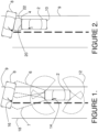
- FIG. 1 depicts a first embodiment of the impact mitigation system installed on a first vehicle 2 involved in a collision threat scenario with a second vehicle 8, which is spunout and stationary in the roadway ahead.
- the forward radiation pattern 6 of a long range ladar sensor embedded in a headlight assembly of first vehicle 2 is shown by dashed lines where it intersects with the driver's side of second vehicle 8, which is positioned laterally across the lane and the right edge of the roadway 9.
- Second vehicle 8 obstructs part of the second lane of traffic, but does not extend over the left edge of the roadway 18.
- a second forward radiation pattern 7 from a second long range ladar sensor embedded in a second headlight assembly is shown overlapping first radiation pattern 6.
- the radiation pattern 12 of a short range ladar sensor embedded in an auxiliary lamp assembly is shown projecting radially from a corner of first vehicle 2 and also at the other three corners of first vehicle 2.
- First vehicle 2 also has a radio antenna 14 for communicating with second vehicle 8 which also has a radio antenna 16 for receiving radio communications and transmitting responses. Communication may also take the form of optical pulses.
- FIG. 2 shows the evolution of FIG. 1 in a situation where first vehicle 2 is unable to stop in time to avoid a collision with second vehicle 8.
- This scenario could easily evolve on a rain-slickened or icy roadway, or in the case of a second vehicle 8 emerging from a blind alley perpendicular and to the right of the roadway edge 9.
- the headlight assembly 4 containing a long range ladar sensor is shown on first vehicle 2.
- the auxiliary lamp assembly 10 containing a short range ladar sensor typically positioned at the four corners of first vehicle 2.
- An external airbag 22 has been deployed from airbag panel 20 mounted in the front bumper area of first vehicle 2.
- the first vehicle 2 has determined an impact is likely from analyzing object data developed from an array of available data, including long range and short range ladar sensors, video/still cameras, GPS or relative position references, and two way communications with second vehicle 8, and has deployed airbag 22 to reduce the closing speed between the vehicles in an unavoidable impact. It is also possible that second vehicle 8 by means of a side sensor could detect the danger and deploy an external side air bag. The situation would be similar to Figure 2 .
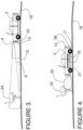
- FIG. 3 shows a collision threat scenario involving first vehicle 2 and a biped 24 in the roadway 18 ahead.
- first vehicle 2 has a conical radiation pattern 6 emanating from a long range ladar sensor embedded in headlight assembly 4, for example, and which illuminates biped 24 and returns range data sufficient to create a 3D model.
- the 3D range data derived from the reflections of the modulated laser light allows for some object identification to take place in a processor of the impact mitigation system installed on first vehicle 2.
- Short range radiation pattern 12 issues from a short range ladar sensor which is embedded in auxiliary lamp assembly 10, and covers the ground immediately in front of first vehicle 2.
- Auxiliary lamp assembly 10 in this diagram is embedded in a corner mounted turn signal, as depicted in Figure 1 .
- An airbag system is contained in airbag panel 20 located in the front bumper of first vehicle 2.
- FIG. 4 shows a side view of the moment of impact between first vehicle 2 and biped 24.
- Airbag 22 is fully deployed and ready to absorb the impact to reduce damage to the vehicle 2 and to soften the blow delivered to biped 24.
- Front wheel 21 may actively lower to prevent the possibility of first vehicle 2 knocking biped 24 over and running over it or dragging it.
- Rear wheel 17 may lower as well, or may remain in position.
- auxiliary lamp assembly 10 a tail light in this case, which may have a short range ladar sensor embedded.
- Ladar sensors may be mounted at many points on the vehicle 2; door panels, rear view mirrors, bumpers, etc.
- Rear bumper 26 and door panels 19 may also have external airbag systems as well which may be activated in the event of a rear or side impact to first vehicle 2.
- FIG. 8 is another embodiment of a gas venting system for the external airbag 22.
- Airbag panel 20 is configured with a series of slots 53 which may be covered by solid sections of sliding plate 49, or opened to a partially open position when the slots 51 and 53 are partially overlapping.
- a maximum gas venting aperture is created by the fully open position when the slots 51 of sliding plate 49 are directly atop the slots 53 of airbag panel 20.
- a U-shaped channel 59 at the bottom of airbag panel 20 guides sliding plate 49, and holds it in position to act as a variable gas valve for venting external airbag 22 after deployment.
- a second U-shaped channel (not shown) at the top of airbag panel 20 retains and guides sliding plate 49, and retains it in position to be effective as a variable aperture gas valve.
- Bidirectional electrical connections 112 serve to transfer 3D data maps, status, and control signals between ladar system controller 104 and the vehicle electrical systems and central processing unit (CPU) 114.
- CPU central processing unit
- an electronic brain may control all functioning of the vehicle 2, and typically controls all other subsystems and co-processors.
- the electronic brain, or central processing unit (CPU 114) is here lumped together with the basic electrical systems of the vehicle, including battery, headlights, wiring harness, etc.
- the vehicle suspension system 116 receives control commands and returns status through bidirectional electrical connections, and is capable of modifying the ride height, spring rate, and damping rate of each of the four wheels independently.
- An inertial reference 120 also has a vertical reference, or gravity sensor as an input to the CPU 114.
- a collision processor and airbag control unit 118 connects bidirectionally to CPU 114 as well, receiving inputs from a number of accelerometers, brake sensors, wheel rotational sensors, ladar sensors, etc. and makes decisions on the timing and deployment of both internal and external airbags 22.
- ACU 118 also controls the venting of external airbags 22 through bidirectional electrical connections to a number of vent controls 99 situated in the various external airbag units on the vehicle 2.
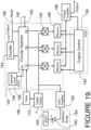
- FIG 17 shows additional details of the ladar system controller 104 and interconnections to the suite of ladar sensors.
- the ladar system controller 104 comprises a sensor interface 126, which transmits commands to the short range ladar sensors SRU1-4 ( 100, 102, 106, and 108), and to the long range ladar sensors LRU1 94, and LRU2 96.
- a fiber cable and wire harness 124 provides the physical media for the transfer of the commands from the sensor interface 126 to the various ladar sensors. 3D data and status signals are returned from the various ladar sensors to sensor interface 126 through fiber cable and wire harness 124.
- command signals are sent to a number (n) of 2D cameras 97, and status and image data are returned therefrom, via wire harness 124 to ladar system controller 104.
- Each long range sensor unit (94, 96) connects through a set of bidirectional connections 98 which logically include the transmitters and receivers within each long range sensor unit (94, 96), the physical media of fiber cable and wire harness 124, and the transmitters and receivers of sensor interface 126.
- Each short range sensor unit (100,102,106,108) connects through a set of bidirectional connections 110 which logically include the transmitters and receivers within each short range sensor unit (100,102,106,108), the physical media of fiber cable and wire harness 124, and the transmitters and receivers of sensor interface 126.
- sampling frequency of sample clock 196 would also be selected to produce 10 or perhaps 20, analog samples during each pulse width.
- the sampling impedance control 193 When the sampling impedance control 193 is set to a minimum, the sample controls S1, S2, S3... turn on with full voltage during a sampling cycle. Since each sampling gate 190 is a field effect transistor, increasing the sample control voltage S1-S3 will increase the gate-source voltage on the sampling FET, thus lowering the impedance of the channel between source and drain, and setting the sampling gate impedance to a minimum.
- the sampling gate 190 impedance is set to a minimum, the storage capacitor serving as analog memory cell 188 charges rapidly to the voltage present at the output of input amplifier 182.
- This second sampling mode may be very useful when a sinusoidal modulation is applied to the pulsed laser transmitter 146 in the case where the laser is a semiconductor laser, typically a high efficiency VCSEL.
- a sampling clock to the sampling gate 190 driven by S1
- S1 the same frequency as the sinusoidal modulation
- a sum frequency and a difference frequency will be in the sampled signal
- the analog memory cell 188 storage capacitor will filter out the sum frequency, and the difference frequency will be zero, leaving only a DC voltage component, which will be a trigonometric function of the phase difference.
- this DC voltage Over a number of cycles of the sinusoidal modulation from the output of input amplifier 182, this DC voltage will emerge as the sine or cosine of the phase difference. This phase difference is proportional to the range to a reflecting surface.
- a modulation signal In a third modulation case, two and perhaps three sinewaves of different frequencies are superimposed as a modulation signal on a semiconductor laser, and the received waveform output from input amplifier 182 is sampled by 2 or 3 unit cell sampling structures 197 arranged in parallel, and operating at the 2 or 3 different frequencies of the modulation signal. Each frequency is demodulated and the phase measured by the unit cell sampling structure tuned to the frequency of interest by feeding the appropriate sampling frequency from sample clock 196, typically a copy of the modulation frequency.
- the ladar When measuring the phase of reflected laser energy with respect to a transmitted laser sinewave modulation, certain limits must be observed. If the ladar should have a maximum range capability of 150 meters in free space, the total round trip delay from transmit to receive would be around 1 microsecond. For the phase measurement to be meaningful, the frequency of transmission must therefore be less than 1MHz to avoid spatial (distance) aliasing of targets at the 150 meter limit. In other words, the further the target, the lower the frequency of modulation must be for a single modulation frequency phase measurement to be meaningful. In a conventional sweep radar, the dwell time on the target is limited, so return signals beyond the maximum design range often do not appear as aliased, or "ghost" signals at a shorter apparent range.
- the typical mode is a staring mode, and there is no sweep of the illuminating beam or receiving antenna across the target space. Therefore, in the ladar sensor (94,100) of the present design, responses from targets beyond the designed maximum range could produce an aliased response (one in which the phase shift is greater than 2 ⁇ ).
- a method for resolving these aliased, or "ghost" images is to illuminate the target in a second or third transmission with a slightly different frequency; for example .99MHz versus the 1.0MHz in a first gated sinewave illuminating pulse. If the target image remains at the same apparent range, it is likely a real target at a range less than the design maximum range limit.
- the ladar sensor (94, 100) of the instant invention makes use of a frequency agile transmitter which can rapidly tune from a first transmission frequency to a second transmission frequency, and more if necessary.
- the unit cell sampling structure 197 is doubled or tripled, and operated in parallel, and two or three sinewave modulation signals are superimposed on the semiconductor laser transmitter.
- the individual frequencies should not be simple harmonics of each other; i.e., they should not be related by fractions of low value integers.
- the ladar sensor (94, 100 ) in a preferred embodiment makes use of a semiconductor VCSEL laser, enabling the use of shaped single pulses, shaped multiple pulses, shaped and encoded multiple pulses, gated sinewave, gated chirped sinewave, and multi-frequency gated sinewave modulation schemes.
- a low power semiconductor laser may be electronically modulated, and the resulting modulated optical output amplified by an optical amplifier.
- Figure 20 is a diagram showing the mating of detector array 154 with readout IC 156.
- Row amplifiers 206 and column amplifiers 204 allow the output from a unit cell electrical circuit 208 to be output as part of a row output or column output read cycle. All signals to and from readout IC 156 are communicated through bond pads 202 at the periphery of the ROIC 156.
- Atop each unit cell electrical circuit 208 is an indium bump 210 which is compressed and deformed under temperature and pressure as part of the bonding process which mates detector array 154 to readout IC 156.
- the indium bump 210 may instead be a low temperature solder bump, which may be reflowed to permanently bond detector array 154 to readout IC 156.
- the arrow shows the direction of mating, and the top of detector array 154 shows the grid pattern of an optional microlens array comprised of lens elements 200 which collect and focus light into each of the individual detector elements of detector array 154 formed on the anterior surface.
Landscapes
- Engineering & Computer Science (AREA)
- Physics & Mathematics (AREA)
- Radar, Positioning & Navigation (AREA)
- Remote Sensing (AREA)
- General Physics & Mathematics (AREA)
- Mechanical Engineering (AREA)
- Computer Networks & Wireless Communication (AREA)
- Electromagnetism (AREA)
- Traffic Control Systems (AREA)
- Multimedia (AREA)
- Air Bags (AREA)
- Lighting Device Outwards From Vehicle And Optical Signal (AREA)
- Optical Radar Systems And Details Thereof (AREA)
- Vehicle Body Suspensions (AREA)
- Automation & Control Theory (AREA)
Claims (10)
- Aufprallmilderungssystem, das Folgendes umfasst:ein Fahrzeug miteiner aktiven Aufhängungskomponente (61), wobei die aktive Aufhängungskomponente an einem Lenker (46) wenigstens eines Rads (36) des Fahrzeugs angebracht ist,wobei die aktive Aufhängungskomponente außerdem an einem Fahrwerk des Fahrzeugs angebracht ist und wobei die aktive Aufhängungskomponente in der Lage ist, das Rad in Reaktion auf eine Aufhängungssteuereingabe von einer Zentraleinheit aktiv anzuheben oder abzusenken,einem ersten langreichweitigen Lidarsensor (94) und einem zweiten langreichweitigen Lidarsensor (96), wovon sich jeder in jeweiligen Scheinwerferanordnungen (4) befindet und ein konisches Strahlungsmuster aufweist und ein erstes Blickfeld aufweist und einen langreichweitigen 3D-Rahmen erzeugt,einem ersten kurzreichweitigen Lidarsensor (102, 100) und einem zweiten kurzreichweitigen Lidarsensor (106, 108), wovon sich jeder in jeweiligen Zusatzleuchtenanordnungen (10) befindet und ein kurzreichweitiges Strahlungsmuster ausgibt, das den Boden unmittelbar vor dem Fahrzeug überdeckt, wobei die kurzreichweitigen Lidarsensoren einen weiteren Divergenzwinkel als die langreichweitigen Lidarsensoren (94, 96) aufweisen und einen kurzreichweitigen 3D-Rahmen erzeugen,wobei jeder der langreichweitigen und kurzreichweitigen Lidarsensoren Folgendes umfasst:eine Empfangslinsenanordnung (152),einen Lasersender (146) mit einem Ausgang für moduliertes Laserlicht und mit einer Streuoptik zum Beleuchten einer Szene in dem jeweiligen Blickfeld der Lidarsensoren,eine zweidimensionale Anordnung lichtempfindlicher Detektoren (154), die in einer Brennebene der Empfangslinsenanordnung positioniert sind, wobei jeder der lichtempfindlichen Detektoren einen Ausgang hat, der aus einem reflektierten Teil der modulierten Laserlichtausgabe ein elektrisches Antwortsignal erzeugt,einen Detektorvorspannungsumsetzer (166), der mit wenigstens einem Spannungsverteilungsgitter der Anordnung lichtempfindlicher Detektoren verbunden ist,eine integrierte Ausleseschaltung (156) mit mehreren elektrischen Einheitszellenschaltungen, wobei jede der elektrischen Einheitszellenschaltungen einen Eingang, der mit einem der Ausgänge lichtempfindlicher Detektoren verbunden ist, aufweist, wobei jede elektrische Einheitszellenschaltung einen Demodulator für elektrische Antwortsignale und eine Einheitszellen-Entfernungsmessschaltung, die mit einem Ausgang des Demodulators für elektrische Antwortsignale verbunden ist, aufweist, wobei die Einheitszellen-Entfernungsmessschaltung ferner mit einem Referenzsignal, das für die Entfernungsmessschaltung eine Null-Entfernungsreferenz bereitstellt, verbunden ist, wobei jede Einheitszellen-Entfernungsmessschaltung eine digitale Ausgabe (162) für den 3D-Rahmen bereitstellt, wobei die digitale Ausgabe (162) eine digitale Darstellung unkorrigierter analoger Abtastwerte ist, wobei ein Datenreduktionsprozessor (164) die digitale Ausgabe (162) empfängt, wobei der Datenreduktionsprozessor den Nennentfernungsmesswert, der von jeder Einheitszelle empfangen wird, durch eine Kurve, die die analogen Abtastwerte an eine Form eines abgehenden Laserbeleuchtungsimpulses anpasst, verfeinert und ein volles Einzelbild ausgibt,einen Speicher (176) für langreichweitige Rahmen, der in den langreichweitigen Lidarsensor eingebaut ist und zum Empfangen des langreichweitigen 3D-Rahmens verbunden ist und der ausgelegt ist, langreichweitige Daten zu speichern,einen Speicher (176) für kurzreichweitige Rahmen, der in den kurzreichweitigen Lidarsensor eingebaut ist und zum Empfangen des kurzreichweitigen 3D-Rahmens verbunden ist und der ausgelegt ist, kurzreichweitige Entfernungsdaten zu speichern,einen digitalen Prozessor (132), der zum Empfangen von 3D-Daten von dem Speicher für kurzreichweitige Rahmen undvon dem Speicher für langreichweitige Rahmen angeschlossen ist und ausgelegt ist, eine Eingabe in den Aufhängungssteuerungsprozessor bereitzustellen, undeine temperaturstabilisierte Frequenzreferenz (168), die mit dem digitalen Prozessor (136) verbunden ist, um Taktsignale bereitzustellen.
- Aufprallmilderungssystem nach Anspruch 1, das ferner eine Duplexfunkverbindung (115) umfasst, die mit dem digitalen Prozessor verbunden ist, um ihn mit einem zweiten digitalen Prozessor in einem zweiten Fahrzeug zu verbinden.
- Aufprallmilderungssystem nach Anspruch 1, wobei der Lasersender (146) einen oberflächenemittierenden Laser mit vertikalem Hohlraum umfasst, der in einem Halbleiterverstärkungsmedium mit wenigstens einem Element, das aus der Gruppe ausgewählt ist, die Indium, Gallium, Arsen, Phosphor enthält, gebildet ist.
- Aufprallmilderungssystem nach Anspruch 1, wobei die modulierte Laserlichtausgabe mit einer Signalform moduliert ist, die aus der Gruppe ausgewählt ist, die ein einzelnes Gauß-Impuls-Profil, mehrere Gauß-Profil-Impulse, ein einzelnes abgeflachtes Impulsprofil, mehrere abgeflachte Impulse, eine gepulste Sinusschwingung und einen gechirpten Sinusschwingungsimpuls enthält.
- Aufprallmilderungssystem nach Anspruch 1, wobei der Lasersender (146) einen optisch gepumpten Festkörperlaser umfasst, der in einem Verstärkungsmedium gebildet ist, das aus der Gruppe ausgewählt ist, die Yttrium-Aluminium-Granat, mit Erbium dotierten Glas, mit Neodym dotierten Yttrium-Aluminium-Granat und mit Erbium dotierten Yttrium-Aluminium-Granat enthält.
- Aufprallmilderungssystem nach Anspruch 1, wobei die langreichweitigen und/oder die kurzreichweitigen Lidarsensoren (94, 96, 102, 100, 106, 108) in eine Scheinwerferanordnung (4) integriert sind.
- Aufprallmilderungssystem nach Anspruch 1, wobei die kurzreichweitigen Lidarsensoren (94, 96, 102, 100, 106, 108) in eine Zusatzleuchtenanordnung (10) integriert sind, die aus der Gruppe ausgewählt ist, die einen Fahrtrichtungsanzeiger, eine Rückleuchte, eine Parkleuchte, eine Spiegelanordnung und eine Bremsleuchte enthält.
- Aufprallmilderungssystem nach Anspruch 1, wobei das Fahrzeug ferner wenigstens eine zweidimensionale Bilderzeugungskamera (97) aufweist, die so sieht, dass sie ein Blickfeld aufweist, das mit dem Blickfeld wenigstens eines der langreichweitigen oder der kurzreichweitigen Lidarsensoren (94, 96, 102, 100, 106, 108) überlappt, wobei der digitale Prozessor in der Lage ist, die Daten von dem Lidarsensor mit Daten von der wenigstens einen zweidimensionalen Bilderzeugungskamera (97) zu vereinigen.
- System nach Anspruch 1, wobei der Demodulator für elektrische Antwortsignale Folgendes umfasst:einen Eingangsverstärker (182) mit einem Ausgang, der mit einer Auslöseschaltung (170) verbunden ist,eine Reihe analoger Abtastgatter (190), wobei jedes Abtastgatter eine zugeordnete analogen Speicherzelle (188) enthält und wobei jedes der Abtastgatter mit einem Ausgang des Eingangsverstärkers (182) verbunden ist,einen Abtasttaktgeber (196), der die Zeiteinstellung jedes der Abtastgatter (190) steuert,eine Auswahleinrichtung (192) zum Auswählen jedes der Abtastgatter (190) in einer Folge,einen Zähler (194) zum Zählen der Anzahl der Abtastwerte,einen Ausgangsverstärker mit einem Eingang, der mit jeder der analogen Speicherzellen verbunden ist,eine Ausgabesteuerung zum Auswählen einer Folge der analogen Speicherzelleninhalte, die über den Ausgangsverstärker (186) ausgegeben werden sollen,und wobei ein Eingang eines Analog/Digital-Umsetzers (144) mit dem Ausgangsverstärker (186) verbunden ist,wobei ein Ausgang des Analog/Digital-Umsetzers (144) mit einem Eingang eines digitalen Prozessors verbunden ist und wobei der Analog/Digital-Umsetzer (144) eine Folge digitalisierter analoger Abtastwerte des elektrischen Antwortsignals erzeugt und wobei der digitale Prozessor programmiert ist, das elektrische Antwortsignal durch Bearbeiten der Folge digitaler analoger Abtastwerte unter Verwendung eines digitalen Verarbeitungsalgorithmus zu demodulieren.
- System nach Anspruch 1, wobei die Aufhängungssteuerungseingabe pneumatisch, hydraulisch oder elektrisch ist.
Applications Claiming Priority (2)
| Application Number | Priority Date | Filing Date | Title |
|---|---|---|---|
| US13/791,180 US9110169B2 (en) | 2013-03-08 | 2013-03-08 | LADAR enabled impact mitigation system |
| EP14157718.9A EP2775316A3 (de) | 2013-03-08 | 2014-03-04 | LADAR-aktiviertes Zusammenprallabschwächungssystem |
Related Parent Applications (1)
| Application Number | Title | Priority Date | Filing Date |
|---|---|---|---|
| EP14157718.9A Division EP2775316A3 (de) | 2013-03-08 | 2014-03-04 | LADAR-aktiviertes Zusammenprallabschwächungssystem |
Publications (2)
| Publication Number | Publication Date |
|---|---|
| EP3663793A1 EP3663793A1 (de) | 2020-06-10 |
| EP3663793B1 true EP3663793B1 (de) | 2025-06-25 |
Family
ID=50230932
Family Applications (2)
| Application Number | Title | Priority Date | Filing Date |
|---|---|---|---|
| EP14157718.9A Withdrawn EP2775316A3 (de) | 2013-03-08 | 2014-03-04 | LADAR-aktiviertes Zusammenprallabschwächungssystem |
| EP19204079.8A Active EP3663793B1 (de) | 2013-03-08 | 2014-03-04 | Ladar-aktiviertes auswirkungsabschwächungssystem |
Family Applications Before (1)
| Application Number | Title | Priority Date | Filing Date |
|---|---|---|---|
| EP14157718.9A Withdrawn EP2775316A3 (de) | 2013-03-08 | 2014-03-04 | LADAR-aktiviertes Zusammenprallabschwächungssystem |
Country Status (3)
| Country | Link |
|---|---|
| US (5) | US9110169B2 (de) |
| EP (2) | EP2775316A3 (de) |
| JP (1) | JP2014174176A (de) |
Families Citing this family (135)
| Publication number | Priority date | Publication date | Assignee | Title |
|---|---|---|---|---|
| USRE46672E1 (en) | 2006-07-13 | 2018-01-16 | Velodyne Lidar, Inc. | High definition LiDAR system |
| US8285447B2 (en) * | 2007-03-20 | 2012-10-09 | Enpulz, L.L.C. | Look ahead vehicle suspension system |
| WO2012137332A1 (ja) * | 2011-04-07 | 2012-10-11 | パイオニア株式会社 | 移動体の周囲状況検知システム |
| US9383753B1 (en) * | 2012-09-26 | 2016-07-05 | Google Inc. | Wide-view LIDAR with areas of special attention |
| DE102013100522A1 (de) * | 2013-01-18 | 2014-08-07 | Huf Hülsbeck & Fürst Gmbh & Co. Kg | Universelle Sensoranordnung zur Erfassung von Bediengesten an Fahrzeugen |
| US9110169B2 (en) * | 2013-03-08 | 2015-08-18 | Advanced Scientific Concepts, Inc. | LADAR enabled impact mitigation system |
| AU2014239979B2 (en) | 2013-03-15 | 2017-06-22 | Aurora Operations, Inc. | Methods, systems, and apparatus for multi-sensory stereo vision for robotics |
| US10132626B2 (en) * | 2013-09-18 | 2018-11-20 | Infineon Technologies Ag | Adaptive distance estimation |
| JP6524472B2 (ja) * | 2014-01-23 | 2019-06-05 | ジョイソン セイフティ システムズ アクイジション エルエルシー | 車両用の乗員識別システム、並びに車両用の乗員識別およびシートヒータシステム |
| US9407319B2 (en) * | 2014-03-24 | 2016-08-02 | Sital Technology Ltd. | Fault tolerant transceiver |
| US20150336546A1 (en) * | 2014-05-19 | 2015-11-26 | Umm Al-Qura University | Method and system for vehicle to sense roadblock |
| GB2527510B (en) * | 2014-06-23 | 2016-12-14 | Jaguar Land Rover Ltd | Launch speed ratio selection in an automatic transmission |
| US10088558B2 (en) | 2014-08-15 | 2018-10-02 | Aeye, Inc. | Method and system for ladar transmission with spiral dynamic scan patterns |
| US9994184B2 (en) * | 2015-03-31 | 2018-06-12 | Ford Global Technologies, Llc | Vehicle side airbag with secondary chamber |
| US9505404B2 (en) * | 2015-04-10 | 2016-11-29 | Jaguar Land Rover Limited | Collision avoidance system |
| US9598078B2 (en) | 2015-05-27 | 2017-03-21 | Dov Moran | Alerting predicted accidents between driverless cars |
| US10031522B2 (en) | 2015-05-27 | 2018-07-24 | Dov Moran | Alerting predicted accidents between driverless cars |
| WO2017017967A1 (ja) * | 2015-07-29 | 2017-02-02 | 京セラ株式会社 | 検出装置、撮像装置、車両および検出方法 |
| US10691958B1 (en) * | 2015-07-30 | 2020-06-23 | Ambarella International Lp | Per-lane traffic data collection and/or navigation |
| US9746852B1 (en) | 2015-08-17 | 2017-08-29 | X Development Llc | Using laser sensors to augment stereo sensor readings for robotic devices |
| US9886035B1 (en) | 2015-08-17 | 2018-02-06 | X Development Llc | Ground plane detection to verify depth sensor status for robot navigation |
| KR20170028126A (ko) * | 2015-09-03 | 2017-03-13 | 엘지전자 주식회사 | 차량 운전 보조 장치 및 차량 |
| JP6555056B2 (ja) * | 2015-09-30 | 2019-08-07 | アイシン精機株式会社 | 周辺監視装置 |
| US11067689B2 (en) | 2015-10-06 | 2021-07-20 | Pioneer Corporation | Information processing device, information processing method and program |
| SE1551370A1 (sv) * | 2015-10-22 | 2017-02-07 | Uniquesec Ab | Testing method with virtual radar signatures for an automotive safety radar system |
| DE102015013802B4 (de) * | 2015-10-23 | 2019-12-24 | Audi Ag | Situationserkennung bei aktiven Fahrwerken |
| US10338225B2 (en) | 2015-12-15 | 2019-07-02 | Uber Technologies, Inc. | Dynamic LIDAR sensor controller |
| US9946259B2 (en) * | 2015-12-18 | 2018-04-17 | Raytheon Company | Negative obstacle detector |
| EP3396410A4 (de) | 2015-12-21 | 2019-08-21 | Koito Manufacturing Co., Ltd. | Bilderfassungsvorrichtung für fahrzeuge, steuerungsvorrichtung, mit der bilderfassungsvorrichtung für fahrzeuge und der steuerungsvorrichtung ausgestattetes fahrzeug bilderfassungsverfahren für fahrzeuge |
| EP3396413A4 (de) | 2015-12-21 | 2019-08-21 | Koito Manufacturing Co., Ltd. | Bilderfassungsvorrichtung für fahrzeuge, steuerungsvorrichtung, mit der bilderfassungsvorrichtung für fahrzeuge und der steuerungsvorrichtung ausgestattetes fahrzeug bilderfassungsverfahren für fahrzeuge |
| EP3396414A4 (de) | 2015-12-21 | 2019-08-21 | Koito Manufacturing Co., Ltd. | Bilderfassungsvorrichtung zur verwendung durch ein fahrzeug, steuerungsvorrichtung, fahrzeug mit der steuerungsvorrichtung oder bilderfassungsvorrichtung zur verwendung durch ein fahrzeug und bilderfassungsverfahren zur verwendung durch ein fahrzeug |
| JP6766072B2 (ja) * | 2015-12-21 | 2020-10-07 | 株式会社小糸製作所 | 車両用センサおよびそれを備えた車両 |
| JP6766071B2 (ja) * | 2015-12-21 | 2020-10-07 | 株式会社小糸製作所 | 車両用画像取得装置およびそれを備えた車両 |
| US10627490B2 (en) | 2016-01-31 | 2020-04-21 | Velodyne Lidar, Inc. | Multiple pulse, LIDAR based 3-D imaging |
| US12399279B1 (en) | 2016-02-15 | 2025-08-26 | Red Creamery Llc | Enhanced hybrid LIDAR with high-speed scanning |
| US12123950B2 (en) | 2016-02-15 | 2024-10-22 | Red Creamery, LLC | Hybrid LADAR with co-planar scanning and imaging field-of-view |
| US12399278B1 (en) | 2016-02-15 | 2025-08-26 | Red Creamery Llc | Hybrid LIDAR with optically enhanced scanned laser |
| US11556000B1 (en) | 2019-08-22 | 2023-01-17 | Red Creamery Llc | Distally-actuated scanning mirror |
| US9933513B2 (en) | 2016-02-18 | 2018-04-03 | Aeye, Inc. | Method and apparatus for an adaptive ladar receiver |
| US20170242102A1 (en) | 2016-02-18 | 2017-08-24 | Aeye, Inc. | Ladar System with Dichroic Photodetector for Tracking the Targeting of a Scanning Ladar Transmitter |
| WO2017143217A1 (en) * | 2016-02-18 | 2017-08-24 | Aeye, Inc. | Adaptive ladar receiver |
| US10042159B2 (en) | 2016-02-18 | 2018-08-07 | Aeye, Inc. | Ladar transmitter with optical field splitter/inverter |
| US20170242104A1 (en) | 2016-02-18 | 2017-08-24 | Aeye, Inc. | Ladar Transmitter with Induced Phase Drift for Improved Gaze on Scan Area Portions |
| US9902229B2 (en) * | 2016-02-19 | 2018-02-27 | GM Global Technology Operations LLC | Methods and systems for optimizing vehicle ride using road preview |
| US10281923B2 (en) | 2016-03-03 | 2019-05-07 | Uber Technologies, Inc. | Planar-beam, light detection and ranging system |
| CA3017735C (en) | 2016-03-19 | 2023-03-14 | Velodyne Lidar, Inc. | Integrated illumination and detection for lidar based 3-d imaging |
| US10120385B2 (en) * | 2016-03-30 | 2018-11-06 | Intel Corporation | Comfort ride vehicle control system |
| US9701307B1 (en) * | 2016-04-11 | 2017-07-11 | David E. Newman | Systems and methods for hazard mitigation |
| US10761195B2 (en) | 2016-04-22 | 2020-09-01 | OPSYS Tech Ltd. | Multi-wavelength LIDAR system |
| US9952317B2 (en) | 2016-05-27 | 2018-04-24 | Uber Technologies, Inc. | Vehicle sensor calibration system |
| WO2017210418A1 (en) | 2016-06-01 | 2017-12-07 | Velodyne Lidar, Inc. | Multiple pixel scanning lidar |
| US10035555B2 (en) * | 2016-07-06 | 2018-07-31 | International Business Machines Corporation | Cognitive stabilizer wheels for vehicles |
| US10488520B2 (en) * | 2016-10-11 | 2019-11-26 | Mitsubishi Electric Research Laboratories, Inc. | Time-of-flight sensor |
| US10379540B2 (en) * | 2016-10-17 | 2019-08-13 | Waymo Llc | Light detection and ranging (LIDAR) device having multiple receivers |
| KR102406502B1 (ko) * | 2016-12-14 | 2022-06-10 | 현대자동차주식회사 | 차량의 협로 주행 안내 장치 및 방법 |
| DE102017201936A1 (de) * | 2017-02-08 | 2018-08-09 | Robert Bosch Gmbh | Verfahren zur Reduzierung eines Kollisionsschadens |
| US10379205B2 (en) | 2017-02-17 | 2019-08-13 | Aeye, Inc. | Ladar pulse deconfliction method |
| KR102592139B1 (ko) | 2017-03-13 | 2023-10-23 | 옵시스 테크 엘티디 | 눈-안전 스캐닝 lidar 시스템 |
| US10479376B2 (en) | 2017-03-23 | 2019-11-19 | Uatc, Llc | Dynamic sensor selection for self-driving vehicles |
| KR102020993B1 (ko) * | 2017-03-29 | 2019-09-11 | 한남대학교 산학협력단 | 초음파 위치 측정 장치 |
| JP7290571B2 (ja) | 2017-03-31 | 2023-06-13 | ベロダイン ライダー ユーエスエー,インコーポレイテッド | 統合化されたlidar照明出力制御 |
| JP2020519881A (ja) | 2017-05-08 | 2020-07-02 | ベロダイン ライダー, インク. | Lidarデータ収集及び制御 |
| US10491807B2 (en) | 2017-06-27 | 2019-11-26 | GM Global Technology Operations LLC | Method to use vehicle information and sensors for photography and video viewing recording |
| US10754033B2 (en) | 2017-06-30 | 2020-08-25 | Waymo Llc | Light detection and ranging (LIDAR) device range aliasing resilience by multiple hypotheses |
| KR102435970B1 (ko) | 2017-07-28 | 2022-08-25 | 옵시스 테크 엘티디 | 작은 각도 발산을 갖는 vcsel 어레이 lidar 송신기 |
| US10627492B2 (en) | 2017-08-01 | 2020-04-21 | Waymo Llc | Use of extended detection periods for range aliasing detection and mitigation in a light detection and ranging (LIDAR) system |
| US10746858B2 (en) | 2017-08-17 | 2020-08-18 | Uatc, Llc | Calibration for an autonomous vehicle LIDAR module |
| US10775488B2 (en) | 2017-08-17 | 2020-09-15 | Uatc, Llc | Calibration for an autonomous vehicle LIDAR module |
| JP6689006B2 (ja) * | 2017-08-25 | 2020-04-28 | ベイジン・ボイジャー・テクノロジー・カンパニー・リミテッド | 車両の環境情報を検出するための方法およびシステム |
| EP3682308B1 (de) | 2017-09-15 | 2024-04-10 | Aeye, Inc. | Intelligentes ladar-system mit aktualisierungen der bewegungsplanung mit geringer latenz |
| US10739444B2 (en) * | 2017-09-18 | 2020-08-11 | Velodyne Lidar, Inc. | LIDAR signal acquisition |
| KR102589319B1 (ko) | 2017-11-15 | 2023-10-16 | 옵시스 테크 엘티디 | 잡음 적응형 솔리드-스테이트 lidar 시스템 |
| US11294041B2 (en) * | 2017-12-08 | 2022-04-05 | Velodyne Lidar Usa, Inc. | Systems and methods for improving detection of a return signal in a light ranging and detection system |
| US20190204845A1 (en) | 2017-12-29 | 2019-07-04 | Waymo Llc | Sensor integration for large autonomous vehicles |
| CN108162850B (zh) * | 2018-01-03 | 2019-10-29 | 京东方科技集团股份有限公司 | 一种灯光控制方法、装置及车辆 |
| US11167709B2 (en) * | 2018-01-22 | 2021-11-09 | Will John Temple | Extendable vehicle bumper |
| US10914820B2 (en) | 2018-01-31 | 2021-02-09 | Uatc, Llc | Sensor assembly for vehicles |
| JP6965784B2 (ja) * | 2018-02-13 | 2021-11-10 | 株式会社リコー | 距離測定装置、およびこれを用いた移動体 |
| KR102192436B1 (ko) * | 2018-03-05 | 2020-12-16 | 주식회사 만도 | 레이다 기반의 타겟 각도 결정 장치 및 방법 |
| KR102604050B1 (ko) | 2018-04-01 | 2023-11-22 | 옵시스 테크 엘티디 | 잡음 적응형 솔리드-스테이트 lidar 시스템 |
| KR102537873B1 (ko) * | 2018-05-08 | 2023-05-30 | 현대자동차주식회사 | 노면 정보를 이용한 차량의 전자제어 서스펜션 제어시스템 및 그를 이용한 제어방법 |
| JP7240657B2 (ja) * | 2018-05-15 | 2023-03-16 | Tokyo Artisan Intelligence株式会社 | ニューラルネットワーク回路装置、ニューラルネットワーク、ニューラルネットワーク処理方法およびニューラルネットワークの実行プログラム |
| US12153163B2 (en) | 2018-08-03 | 2024-11-26 | OPSYS Tech Ltd. | Distributed modular solid-state lidar system |
| US11971507B2 (en) | 2018-08-24 | 2024-04-30 | Velodyne Lidar Usa, Inc. | Systems and methods for mitigating optical crosstalk in a light ranging and detection system |
| CN109163707B (zh) * | 2018-09-06 | 2019-11-26 | 百度在线网络技术(北京)有限公司 | 障碍物感知方法、系统、计算机设备、计算机存储介质 |
| US10712434B2 (en) | 2018-09-18 | 2020-07-14 | Velodyne Lidar, Inc. | Multi-channel LIDAR illumination driver |
| US11121302B2 (en) | 2018-10-11 | 2021-09-14 | SeeQC, Inc. | System and method for superconducting multi-chip module |
| EP3640671B1 (de) * | 2018-10-15 | 2025-01-29 | Integrated Device Technology, Inc. | Lichtdetektions- und entfernungsmesssystem und verfahren zum betreiben und prüfen eines lichtdetektions- und entfernungsmesssystems, insbesondere für sicherheitsrelevante anwendungen |
| US10656252B1 (en) | 2018-10-25 | 2020-05-19 | Aeye, Inc. | Adaptive control of Ladar systems using spatial index of prior Ladar return data |
| US11082010B2 (en) | 2018-11-06 | 2021-08-03 | Velodyne Lidar Usa, Inc. | Systems and methods for TIA base current detection and compensation |
| US20200150238A1 (en) * | 2018-11-13 | 2020-05-14 | Continental Automotive Systems, Inc. | Non-interfering long- and short-range lidar systems |
| US10884419B2 (en) * | 2018-12-18 | 2021-01-05 | Gm Cruise Holdings Llc | Filter for noise reduction in detection in remote sensing systems |
| US10820349B2 (en) | 2018-12-20 | 2020-10-27 | Autonomous Roadway Intelligence, Llc | Wireless message collision avoidance with high throughput |
| US11947038B2 (en) | 2018-12-21 | 2024-04-02 | Continental Automotive Systems, Inc. | Wavelength adaptive narrow band optical filter for a LIDAR system |
| US11885958B2 (en) | 2019-01-07 | 2024-01-30 | Velodyne Lidar Usa, Inc. | Systems and methods for a dual axis resonant scanning mirror |
| US12061263B2 (en) | 2019-01-07 | 2024-08-13 | Velodyne Lidar Usa, Inc. | Systems and methods for a configurable sensor system |
| US10793094B2 (en) * | 2019-02-20 | 2020-10-06 | Ford Global Technologies, Llc | Communication grille assembly |
| FR3093483B1 (fr) | 2019-03-05 | 2022-04-01 | Seva Tech | Interface de communication pour une structure gonflable externe de sécurité piéton équipant un véhicule, protocole de communication structure gonflable-véhicule et module de sécurité associés |
| US10893213B2 (en) * | 2019-04-02 | 2021-01-12 | ACV Auctions Inc. | Vehicle undercarriage imaging system |
| US11770493B2 (en) | 2019-04-02 | 2023-09-26 | ACV Auctions Inc. | Vehicle undercarriage imaging system |
| EP3953727A4 (de) | 2019-04-09 | 2023-01-04 | Opsys Tech Ltd. | Festkörperlidar-sender mit lasersteuerung |
| US10641897B1 (en) | 2019-04-24 | 2020-05-05 | Aeye, Inc. | Ladar system and method with adaptive pulse duration |
| KR20220003600A (ko) | 2019-05-30 | 2022-01-10 | 옵시스 테크 엘티디 | 액추에이터를 사용하는 눈-안전 장거리 lidar 시스템 |
| EP3980808A4 (de) | 2019-06-10 | 2023-05-31 | Opsys Tech Ltd. | Augensicheres festkörper-lidar-system mit grosser reichweite |
| US10820182B1 (en) | 2019-06-13 | 2020-10-27 | David E. Newman | Wireless protocols for emergency message transmission |
| US10939471B2 (en) | 2019-06-13 | 2021-03-02 | David E. Newman | Managed transmission of wireless DAT messages |
| US11390129B1 (en) * | 2019-06-17 | 2022-07-19 | Zoox, Inc. | Pneumatic vehicle suspension system |
| JP7620330B2 (ja) | 2019-06-25 | 2025-01-23 | オプシス テック リミテッド | 適応型多重パルスlidarシステム |
| US10613203B1 (en) | 2019-07-01 | 2020-04-07 | Velodyne Lidar, Inc. | Interference mitigation for light detection and ranging |
| US11334089B1 (en) | 2019-07-26 | 2022-05-17 | Jeffrey W. Bryce | Infrastructure markers for autonomous vehicles |
| KR20220038691A (ko) | 2019-07-31 | 2022-03-29 | 옵시스 테크 엘티디 | 고-해상도 솔리드-상태 lidar 송신기 |
| US11597104B2 (en) | 2019-07-31 | 2023-03-07 | X Development Llc | Mobile robot sensor configuration |
| KR20190104478A (ko) * | 2019-08-20 | 2019-09-10 | 엘지전자 주식회사 | 라이다 시스템과 이를 이용한 자율 주행 시스템 |
| US11624836B2 (en) | 2019-09-24 | 2023-04-11 | Continental Autonomous Mobility US, LLC | Detection of damage to optical element of illumination system |
| US12339390B2 (en) * | 2019-12-04 | 2025-06-24 | Apothym Technologies Group, Llc | Software based cloud computing radar |
| US11579265B2 (en) | 2020-08-19 | 2023-02-14 | Continental Autonomous Mobility US, LLC | Lidar system with crosstalk reduction comprising a power supply circuit layer stacked between an avalanche-type diode layer and a read-out circuit layer |
| KR102896011B1 (ko) * | 2020-10-20 | 2025-12-03 | 현대모비스 주식회사 | 외장 에어백 장치 |
| US12307578B2 (en) * | 2020-11-25 | 2025-05-20 | Nec Corporation | Traffic event reproduction system, server, traffic event reproduction method, and non-transitory computer readable medium |
| WO2022185376A1 (ja) * | 2021-03-01 | 2022-09-09 | パイオニア株式会社 | 情報処理装置、制御方法、プログラム及び記憶媒体 |
| US11486977B2 (en) | 2021-03-26 | 2022-11-01 | Aeye, Inc. | Hyper temporal lidar with pulse burst scheduling |
| US11822016B2 (en) | 2021-03-26 | 2023-11-21 | Aeye, Inc. | Hyper temporal lidar using multiple matched filters to orient a lidar system to a frame of reference |
| US20230044929A1 (en) | 2021-03-26 | 2023-02-09 | Aeye, Inc. | Multi-Lens Lidar Receiver with Multiple Readout Channels |
| US11635495B1 (en) | 2021-03-26 | 2023-04-25 | Aeye, Inc. | Hyper temporal lidar with controllable tilt amplitude for a variable amplitude scan mirror |
| US11630188B1 (en) | 2021-03-26 | 2023-04-18 | Aeye, Inc. | Hyper temporal lidar with dynamic laser control using safety models |
| US11300667B1 (en) | 2021-03-26 | 2022-04-12 | Aeye, Inc. | Hyper temporal lidar with dynamic laser control for scan line shot scheduling |
| US20220308214A1 (en) | 2021-03-26 | 2022-09-29 | Aeye, Inc. | Hyper Temporal Lidar with Controllable Detection Intervals Based on Range Estimates |
| DE102021110820B3 (de) * | 2021-04-28 | 2022-08-04 | Audi Aktiengesellschaft | Radarsensorvorrichtung, Radarsystem mit einer entsprechenden Radarsensorvorrichtung, Kraftfahrzeug, sowie je ein Verfahren zum Betreiben und Herstellen einer Radarsensorvorrichtung |
| US20220396113A1 (en) * | 2021-06-11 | 2022-12-15 | Hak Soo Kim | Advanced electronically controlled air suspension (ecas) system with image sensors |
| US11947050B2 (en) * | 2021-07-07 | 2024-04-02 | Beijing Voyager Technology Co., Ltd. | Temperature control through thermal recycle |
| KR20230021487A (ko) | 2021-08-05 | 2023-02-14 | 현대자동차주식회사 | 차량용 헤드램프의 레벨링 장치 |
| CN113561911B (zh) * | 2021-08-12 | 2023-03-17 | 森思泰克河北科技有限公司 | 车辆控制方法、装置、毫米波雷达及存储介质 |
| CN119159942B (zh) * | 2023-06-19 | 2025-11-07 | 广州汽车集团股份有限公司 | 半主动悬架控制方法、车载控制器、系统、汽车及介质 |
| CN116930668B (zh) * | 2023-09-15 | 2023-12-05 | 国科大杭州高等研究院 | 电推力器响应时间测量的检测系统与运行方法 |
| US12392730B1 (en) | 2024-08-30 | 2025-08-19 | ACV Auctions Inc. | Systems and techniques for vehicle inspection and condition analysis |
| US20260097734A1 (en) * | 2024-10-08 | 2026-04-09 | Nxp B.V. | Physical collision protection |
Family Cites Families (39)
| Publication number | Priority date | Publication date | Assignee | Title |
|---|---|---|---|---|
| CA1235773A (en) * | 1983-12-23 | 1988-04-26 | Shigeto Nakayama | Device for detecting road surface condition |
| JPH0450015A (ja) * | 1990-06-19 | 1992-02-19 | Mitsubishi Motors Corp | 車両用アクティブサスペンション装置 |
| US5446529A (en) * | 1992-03-23 | 1995-08-29 | Advanced Scientific Concepts, Inc. | 3D imaging underwater laser radar |
| US6133989A (en) * | 1993-02-09 | 2000-10-17 | Advanced Scientific Concepts, Inc. | 3D imaging laser radar |
| JPH0725357A (ja) | 1993-07-09 | 1995-01-27 | Toyota Motor Corp | 車両の前部車体構造 |
| JPH07167954A (ja) * | 1993-12-15 | 1995-07-04 | Nikon Corp | 距離測定装置 |
| JPH07320963A (ja) | 1994-05-19 | 1995-12-08 | Japan Aviation Electron Ind Ltd | 非接触コネクタ |
| US5629524A (en) * | 1995-02-21 | 1997-05-13 | Advanced Scientific Concepts, Inc. | High speed crystallography detector |
| US5646613A (en) * | 1996-05-20 | 1997-07-08 | Cho; Myungeun | System for minimizing automobile collision damage |
| US6362482B1 (en) * | 1997-09-16 | 2002-03-26 | Advanced Scientific Concepts, Inc. | High data rate smart sensor technology |
| JPH1198707A (ja) | 1997-09-25 | 1999-04-09 | Sanyo Electric Co Ltd | 非接触型充電装置 |
| US6414746B1 (en) * | 1999-11-24 | 2002-07-02 | Advanced Scientific Concepts, Inc. | 3-D imaging multiple target laser radar |
| JP2001291400A (ja) | 2000-04-07 | 2001-10-19 | Mitsubishi Electric Corp | 半導体メモリ用のテスト回路 |
| EP1275208B1 (de) | 2000-04-18 | 2004-10-06 | Schleifring und Apparatebau GmbH | Anordnung zur kontaktlosen übertragung elektrischer signale bzw. energie |
| US20020117340A1 (en) * | 2001-01-31 | 2002-08-29 | Roger Stettner | Laser radar based collision avoidance system for stationary or moving vehicles, automobiles, boats and aircraft |
| DE10107273B4 (de) * | 2001-02-16 | 2018-01-11 | Volkswagen Ag | Verfahren zum Steuern einer Sicherheitsvorrichtung für Insassen eines Fahrzeuges sowie Steuergerät |
| USD463383S1 (en) | 2001-06-21 | 2002-09-24 | Hon Hai Precision Ind. Co., Ltd. | GBIC cage |
| JP2003151092A (ja) | 2001-11-12 | 2003-05-23 | Keisuke Kuroda | 実質的に人間が運転状態を制御する機械的または/および電気的な動力により走行する移動体、および、その運転制御システム。 |
| US6950014B2 (en) * | 2002-02-13 | 2005-09-27 | Ford Global Technologies Llc | Method for operating a pre-crash sensing system in a vehicle having external airbags |
| GB2389342A (en) * | 2002-06-05 | 2003-12-10 | Autoliv Dev | Air-bag with vent opened by pivoting gas generator |
| DE10392601B4 (de) * | 2002-08-09 | 2023-01-19 | Conti Temic Microelectronic Gmbh | Verkehrsmittel mit einer 3D-Entfernungsbildkamera und Verfahren zu dessen Betrieb |
| US6860350B2 (en) * | 2002-12-20 | 2005-03-01 | Motorola, Inc. | CMOS camera with integral laser ranging and velocity measurement |
| JP2005238992A (ja) * | 2004-02-26 | 2005-09-08 | Hitachi Ltd | 車両の制御装置 |
| US7320478B2 (en) * | 2004-10-18 | 2008-01-22 | Ford Global Technologies Llc | Smart airbag for vehicular applications |
| JP2006273262A (ja) * | 2005-03-30 | 2006-10-12 | Mazda Motor Corp | エアバッグシステム |
| KR101321303B1 (ko) * | 2005-12-08 | 2013-10-25 | 어드밴스트 사이언티픽 컨셉츠 인크. | 3d 초점면을 사용하는 레이저 범위측정과 추적 및 지정 |
| US20090254779A1 (en) | 2006-06-23 | 2009-10-08 | Mitsubishi Electric Corporation | Control apparatus |
| EP1901093B1 (de) | 2006-09-15 | 2018-11-14 | Triple-IN Holding AG | Aufnahme von Entfernungsbildern |
| US8285447B2 (en) * | 2007-03-20 | 2012-10-09 | Enpulz, L.L.C. | Look ahead vehicle suspension system |
| EP2026246A1 (de) * | 2007-08-03 | 2009-02-18 | Harman/Becker Automotive Systems GmbH | Verfahren und Vorrichtung zur Auswertung eines Bildes |
| US8027029B2 (en) * | 2007-11-07 | 2011-09-27 | Magna Electronics Inc. | Object detection and tracking system |
| JP2009143435A (ja) * | 2007-12-14 | 2009-07-02 | Toyota Motor Corp | 車両制御装置 |
| US8031062B2 (en) * | 2008-01-04 | 2011-10-04 | Smith Alexander E | Method and apparatus to improve vehicle situational awareness at intersections |
| US8305270B2 (en) | 2009-04-27 | 2012-11-06 | Texas Instruments Incorporated | Antenna selection for GNSS receivers |
| JP2011037308A (ja) * | 2009-08-06 | 2011-02-24 | Aisin Seiki Co Ltd | 車両用乗員保護システム |
| US8306672B2 (en) * | 2009-09-09 | 2012-11-06 | GM Global Technology Operations LLC | Vehicular terrain detection system and method |
| US9277204B2 (en) * | 2013-01-23 | 2016-03-01 | Advanced Scientific Concepts, Inc. | Modular LADAR sensor |
| US9110169B2 (en) * | 2013-03-08 | 2015-08-18 | Advanced Scientific Concepts, Inc. | LADAR enabled impact mitigation system |
| KR20240010531A (ko) | 2017-04-27 | 2024-01-23 | 스냅 인코포레이티드 | 변칙성 포스팅에 대한 대상물을 표면화하는 방법 및 시스템 |
-
2013
- 2013-03-08 US US13/791,180 patent/US9110169B2/en active Active
-
2014
- 2014-03-04 EP EP14157718.9A patent/EP2775316A3/de not_active Withdrawn
- 2014-03-04 EP EP19204079.8A patent/EP3663793B1/de active Active
- 2014-03-07 JP JP2014045082A patent/JP2014174176A/ja active Pending
-
2015
- 2015-07-30 US US14/813,591 patent/US10295670B2/en active Active
-
2019
- 2019-02-28 US US16/289,087 patent/US10802149B2/en active Active
-
2020
- 2020-09-14 US US17/019,457 patent/US11400877B2/en active Active
-
2022
- 2022-06-28 US US17/851,875 patent/US11702022B2/en active Active
Also Published As
| Publication number | Publication date |
|---|---|
| US9110169B2 (en) | 2015-08-18 |
| EP3663793A1 (de) | 2020-06-10 |
| EP2775316A2 (de) | 2014-09-10 |
| US20190196021A1 (en) | 2019-06-27 |
| US20220348158A1 (en) | 2022-11-03 |
| US11702022B2 (en) | 2023-07-18 |
| US20150202939A1 (en) | 2015-07-23 |
| JP2014174176A (ja) | 2014-09-22 |
| EP2775316A3 (de) | 2015-09-30 |
| US10295670B2 (en) | 2019-05-21 |
| US10802149B2 (en) | 2020-10-13 |
| US20210003713A1 (en) | 2021-01-07 |
| US20150331113A1 (en) | 2015-11-19 |
| US11400877B2 (en) | 2022-08-02 |
Similar Documents
| Publication | Publication Date | Title |
|---|---|---|
| US11702022B2 (en) | Ladar enabled impact mitigation system | |
| US12162475B2 (en) | Automotive auxiliary LADAR sensor | |
| US12292533B2 (en) | Beam steering LADAR sensor | |
| US11846707B2 (en) | Ultrasonic vibrations on a window in a lidar system | |
| CN115087882B (zh) | 用于lidar传感器的高动态范围接收器 | |
| JP2014174176A5 (de) | ||
| US9575184B2 (en) | LADAR sensor for a dense environment | |
| US20180284244A1 (en) | Method for Dynamically Controlling Laser Power |
Legal Events
| Date | Code | Title | Description |
|---|---|---|---|
| PUAI | Public reference made under article 153(3) epc to a published international application that has entered the european phase |
Free format text: ORIGINAL CODE: 0009012 |
|
| STAA | Information on the status of an ep patent application or granted ep patent |
Free format text: STATUS: THE APPLICATION HAS BEEN PUBLISHED |
|
| AC | Divisional application: reference to earlier application |
Ref document number: 2775316 Country of ref document: EP Kind code of ref document: P |
|
| AK | Designated contracting states |
Kind code of ref document: A1 Designated state(s): AL AT BE BG CH CY CZ DE DK EE ES FI FR GB GR HR HU IE IS IT LI LT LU LV MC MK MT NL NO PL PT RO RS SE SI SK SM TR |
|
| STAA | Information on the status of an ep patent application or granted ep patent |
Free format text: STATUS: REQUEST FOR EXAMINATION WAS MADE |
|
| 17P | Request for examination filed |
Effective date: 20201207 |
|
| RBV | Designated contracting states (corrected) |
Designated state(s): AL AT BE BG CH CY CZ DE DK EE ES FI FR GB GR HR HU IE IS IT LI LT LU LV MC MK MT NL NO PL PT RO RS SE SI SK SM TR |
|
| STAA | Information on the status of an ep patent application or granted ep patent |
Free format text: STATUS: EXAMINATION IS IN PROGRESS |
|
| 17Q | First examination report despatched |
Effective date: 20220311 |
|
| GRAP | Despatch of communication of intention to grant a patent |
Free format text: ORIGINAL CODE: EPIDOSNIGR1 |
|
| STAA | Information on the status of an ep patent application or granted ep patent |
Free format text: STATUS: GRANT OF PATENT IS INTENDED |
|
| INTG | Intention to grant announced |
Effective date: 20241127 |
|
| RIN1 | Information on inventor provided before grant (corrected) |
Inventor name: DUERNER, ANDREW Inventor name: GOLDSTEIN, BARTON Inventor name: GILLILAND, PATRICK Inventor name: STETTNER, ROGER |
|
| GRAS | Grant fee paid |
Free format text: ORIGINAL CODE: EPIDOSNIGR3 |
|
| RAP1 | Party data changed (applicant data changed or rights of an application transferred) |
Owner name: CONTINENTAL ADVANCED LIDAR SOLUTIONS US, LLC |
|
| GRAA | (expected) grant |
Free format text: ORIGINAL CODE: 0009210 |
|
| STAA | Information on the status of an ep patent application or granted ep patent |
Free format text: STATUS: THE PATENT HAS BEEN GRANTED |
|
| AC | Divisional application: reference to earlier application |
Ref document number: 2775316 Country of ref document: EP Kind code of ref document: P |
|
| AK | Designated contracting states |
Kind code of ref document: B1 Designated state(s): AL AT BE BG CH CY CZ DE DK EE ES FI FR GB GR HR HU IE IS IT LI LT LU LV MC MK MT NL NO PL PT RO RS SE SI SK SM TR |
|
| REG | Reference to a national code |
Ref country code: GB Ref legal event code: FG4D |
|
| REG | Reference to a national code |
Ref country code: CH Ref legal event code: EP |
|
| REG | Reference to a national code |
Ref country code: CH Ref legal event code: EP |
|
| REG | Reference to a national code |
Ref country code: IE Ref legal event code: FG4D |
|
| REG | Reference to a national code |
Ref country code: DE Ref legal event code: R096 Ref document number: 602014092078 Country of ref document: DE |
|
| PG25 | Lapsed in a contracting state [announced via postgrant information from national office to epo] |
Ref country code: FI Free format text: LAPSE BECAUSE OF FAILURE TO SUBMIT A TRANSLATION OF THE DESCRIPTION OR TO PAY THE FEE WITHIN THE PRESCRIBED TIME-LIMIT Effective date: 20250625 |
|
| REG | Reference to a national code |
Ref country code: LT Ref legal event code: MG9D |
|
| PG25 | Lapsed in a contracting state [announced via postgrant information from national office to epo] |
Ref country code: NO Free format text: LAPSE BECAUSE OF FAILURE TO SUBMIT A TRANSLATION OF THE DESCRIPTION OR TO PAY THE FEE WITHIN THE PRESCRIBED TIME-LIMIT Effective date: 20250925 Ref country code: GR Free format text: LAPSE BECAUSE OF FAILURE TO SUBMIT A TRANSLATION OF THE DESCRIPTION OR TO PAY THE FEE WITHIN THE PRESCRIBED TIME-LIMIT Effective date: 20250926 |
|
| PG25 | Lapsed in a contracting state [announced via postgrant information from national office to epo] |
Ref country code: BG Free format text: LAPSE BECAUSE OF FAILURE TO SUBMIT A TRANSLATION OF THE DESCRIPTION OR TO PAY THE FEE WITHIN THE PRESCRIBED TIME-LIMIT Effective date: 20250625 |
|
| PG25 | Lapsed in a contracting state [announced via postgrant information from national office to epo] |
Ref country code: HR Free format text: LAPSE BECAUSE OF FAILURE TO SUBMIT A TRANSLATION OF THE DESCRIPTION OR TO PAY THE FEE WITHIN THE PRESCRIBED TIME-LIMIT Effective date: 20250625 |
|
| PG25 | Lapsed in a contracting state [announced via postgrant information from national office to epo] |
Ref country code: RS Free format text: LAPSE BECAUSE OF FAILURE TO SUBMIT A TRANSLATION OF THE DESCRIPTION OR TO PAY THE FEE WITHIN THE PRESCRIBED TIME-LIMIT Effective date: 20250925 |
|
| PG25 | Lapsed in a contracting state [announced via postgrant information from national office to epo] |
Ref country code: LV Free format text: LAPSE BECAUSE OF FAILURE TO SUBMIT A TRANSLATION OF THE DESCRIPTION OR TO PAY THE FEE WITHIN THE PRESCRIBED TIME-LIMIT Effective date: 20250625 |
|
| REG | Reference to a national code |
Ref country code: NL Ref legal event code: MP Effective date: 20250625 |
|
| PG25 | Lapsed in a contracting state [announced via postgrant information from national office to epo] |
Ref country code: NL Free format text: LAPSE BECAUSE OF FAILURE TO SUBMIT A TRANSLATION OF THE DESCRIPTION OR TO PAY THE FEE WITHIN THE PRESCRIBED TIME-LIMIT Effective date: 20250625 |
|
| PG25 | Lapsed in a contracting state [announced via postgrant information from national office to epo] |
Ref country code: PT Free format text: LAPSE BECAUSE OF FAILURE TO SUBMIT A TRANSLATION OF THE DESCRIPTION OR TO PAY THE FEE WITHIN THE PRESCRIBED TIME-LIMIT Effective date: 20251027 |
|
| REG | Reference to a national code |
Ref country code: AT Ref legal event code: MK05 Ref document number: 1807003 Country of ref document: AT Kind code of ref document: T Effective date: 20250625 |
|
| PG25 | Lapsed in a contracting state [announced via postgrant information from national office to epo] |
Ref country code: IS Free format text: LAPSE BECAUSE OF FAILURE TO SUBMIT A TRANSLATION OF THE DESCRIPTION OR TO PAY THE FEE WITHIN THE PRESCRIBED TIME-LIMIT Effective date: 20251025 |
|
| PG25 | Lapsed in a contracting state [announced via postgrant information from national office to epo] |
Ref country code: AT Free format text: LAPSE BECAUSE OF FAILURE TO SUBMIT A TRANSLATION OF THE DESCRIPTION OR TO PAY THE FEE WITHIN THE PRESCRIBED TIME-LIMIT Effective date: 20250625 Ref country code: SM Free format text: LAPSE BECAUSE OF FAILURE TO SUBMIT A TRANSLATION OF THE DESCRIPTION OR TO PAY THE FEE WITHIN THE PRESCRIBED TIME-LIMIT Effective date: 20250625 |
|
| PG25 | Lapsed in a contracting state [announced via postgrant information from national office to epo] |
Ref country code: CZ Free format text: LAPSE BECAUSE OF FAILURE TO SUBMIT A TRANSLATION OF THE DESCRIPTION OR TO PAY THE FEE WITHIN THE PRESCRIBED TIME-LIMIT Effective date: 20250625 |
|
| PG25 | Lapsed in a contracting state [announced via postgrant information from national office to epo] |
Ref country code: PL Free format text: LAPSE BECAUSE OF FAILURE TO SUBMIT A TRANSLATION OF THE DESCRIPTION OR TO PAY THE FEE WITHIN THE PRESCRIBED TIME-LIMIT Effective date: 20250625 |
|
| PG25 | Lapsed in a contracting state [announced via postgrant information from national office to epo] |
Ref country code: EE Free format text: LAPSE BECAUSE OF FAILURE TO SUBMIT A TRANSLATION OF THE DESCRIPTION OR TO PAY THE FEE WITHIN THE PRESCRIBED TIME-LIMIT Effective date: 20250625 |
|
| PG25 | Lapsed in a contracting state [announced via postgrant information from national office to epo] |
Ref country code: SK Free format text: LAPSE BECAUSE OF FAILURE TO SUBMIT A TRANSLATION OF THE DESCRIPTION OR TO PAY THE FEE WITHIN THE PRESCRIBED TIME-LIMIT Effective date: 20250625 |
|
| PG25 | Lapsed in a contracting state [announced via postgrant information from national office to epo] |
Ref country code: ES Free format text: LAPSE BECAUSE OF FAILURE TO SUBMIT A TRANSLATION OF THE DESCRIPTION OR TO PAY THE FEE WITHIN THE PRESCRIBED TIME-LIMIT Effective date: 20250625 |
|
| PG25 | Lapsed in a contracting state [announced via postgrant information from national office to epo] |
Ref country code: DK Free format text: LAPSE BECAUSE OF FAILURE TO SUBMIT A TRANSLATION OF THE DESCRIPTION OR TO PAY THE FEE WITHIN THE PRESCRIBED TIME-LIMIT Effective date: 20250625 |
|
| PG25 | Lapsed in a contracting state [announced via postgrant information from national office to epo] |
Ref country code: IT Free format text: LAPSE BECAUSE OF FAILURE TO SUBMIT A TRANSLATION OF THE DESCRIPTION OR TO PAY THE FEE WITHIN THE PRESCRIBED TIME-LIMIT Effective date: 20250625 |
|
| PLBE | No opposition filed within time limit |
Free format text: ORIGINAL CODE: 0009261 |
|
| STAA | Information on the status of an ep patent application or granted ep patent |
Free format text: STATUS: NO OPPOSITION FILED WITHIN TIME LIMIT |
|
| REG | Reference to a national code |
Ref country code: CH Ref legal event code: L10 Free format text: ST27 STATUS EVENT CODE: U-0-0-L10-L00 (AS PROVIDED BY THE NATIONAL OFFICE) Effective date: 20260507 |