EP3663700A1 - Darts-spielvorrichtung - Google Patents
Darts-spielvorrichtung Download PDFInfo
- Publication number
- EP3663700A1 EP3663700A1 EP18842106.9A EP18842106A EP3663700A1 EP 3663700 A1 EP3663700 A1 EP 3663700A1 EP 18842106 A EP18842106 A EP 18842106A EP 3663700 A1 EP3663700 A1 EP 3663700A1
- Authority
- EP
- European Patent Office
- Prior art keywords
- dart
- board
- photo
- brightness
- sensors
- Prior art date
- Legal status (The legal status is an assumption and is not a legal conclusion. Google has not performed a legal analysis and makes no representation as to the accuracy of the status listed.)
- Granted
Links
Images


Classifications
-
- F—MECHANICAL ENGINEERING; LIGHTING; HEATING; WEAPONS; BLASTING
- F41—WEAPONS
- F41J—TARGETS; TARGET RANGES; BULLET CATCHERS
- F41J5/00—Target indicating systems; Target-hit or score detecting systems
- F41J5/02—Photo-electric hit-detector systems
-
- A—HUMAN NECESSITIES
- A63—SPORTS; GAMES; AMUSEMENTS
- A63B—APPARATUS FOR PHYSICAL TRAINING, GYMNASTICS, SWIMMING, CLIMBING, OR FENCING; BALL GAMES; TRAINING EQUIPMENT
- A63B65/00—Implements for throwing ; Mechanical projectors, e.g. using spring force
- A63B65/02—Spears or the like ; Javelins
-
- F—MECHANICAL ENGINEERING; LIGHTING; HEATING; WEAPONS; BLASTING
- F41—WEAPONS
- F41J—TARGETS; TARGET RANGES; BULLET CATCHERS
- F41J3/00—Targets for arrows or darts, e.g. for sporting or amusement purposes
- F41J3/0009—Dartboards
- F41J3/0061—Target faces
-
- F—MECHANICAL ENGINEERING; LIGHTING; HEATING; WEAPONS; BLASTING
- F41—WEAPONS
- F41J—TARGETS; TARGET RANGES; BULLET CATCHERS
- F41J3/00—Targets for arrows or darts, e.g. for sporting or amusement purposes
- F41J3/0009—Dartboards
-
- F—MECHANICAL ENGINEERING; LIGHTING; HEATING; WEAPONS; BLASTING
- F41—WEAPONS
- F41J—TARGETS; TARGET RANGES; BULLET CATCHERS
- F41J3/00—Targets for arrows or darts, e.g. for sporting or amusement purposes
- F41J3/02—Indicators or score boards for arrow or dart games
Definitions
- the present invention relates to a dart game apparatus.
- a dart game apparatus where light-emitting sensors and light-receiving sensors are disposed around a dart board, and a position (coordinates) of a dart that hits the dart board is calculated by detecting the interruption of the light emitted from the light-emitting sensors, caused by the dart, is conventionally known (see Patent Document 1).
- Patent Document 2 discloses a technique to calculate a position of a dart by triangulation, based on the brightness of the light (shade of the dart) generated by the dart, out of the brightness of the lights detected by photo-sensors. Patent Document 2 also discloses that all positions of three darts can be calculated by using five photo-sensors.
- Fig. 6 of this application is a diagram depicting an example of calculating each position where three darts hit when five photo-sensors S1 to S5 are disposed on a dart board at equal intervals.
- a dart D1 of the first throw hits a line connecting two photo-sensors S2 and S4
- a dart D2 of the second throw hits a line connecting the other two photo-sensors S3 and S5
- a dart D3 of the third throw hits an intersection of these lines, for example, only one photo-sensor S1, out of the five photo-sensors S1 to S5, can detect the shade of the darts.
- a position of a dart cannot be calculated unless two photo-sensors S can detect the shade of this dart. Therefore, the position of the dart D3 of the third throw cannot be calculated if only one photo-sensor S1 can detect the shade of the dart.
- a number of photo-sensors is n ⁇ 2.
- the positions of all the darts can be calculated.
- Fig. 1 is an external perspective view of a dart game apparatus 10 according to Embodiment 1 of the present invention.
- the dart game apparatus 10 is formed in a vertical rectangular parallelepiped, for example.
- This dart game apparatus 10 provides a player with a dart game in which one player successively throws n number of darts in one round, for example.
- the dart game may include a plurality of game modes in which a number of darts that one player successively throws is different in accordance with the rules.
- n is a maximum number of darts that one player successively throws in each game mode.
- the dart type is not especially limited, and may be a soft tip dart, a hard tip dart or the like, but in Embodiment 1, a case of using soft tip darts will be described.
- the dart game apparatus 10 includes a dart board 12 and a display device 30.
- the dart board 12 is disposed on the front face of the dart game apparatus 10 approximately at a line of sight position when the player is standing.
- the display device 30 displays a still image or a moving image .
- a coin slot, a mode selecting switch and the like are disposed on the front face of the dart game apparatus 10.
- the player inserts coins into the coin slot for game payment, presses a mode selecting switch to select a game mode, and plays a dart game.
- the player stands at a predetermined position facing the dart game apparatus 10, and throws a dart at a predetermined target on the dart board 12.
- the tip of the dart that reaches the dart board 12 hits the dart board 12, the coordinates of the hit position of the dart (hereafter simply called "position") is detected, and the score based on the hit position is displayed on the display device 30.
- position the coordinates of the hit position of the dart
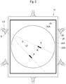
- Fig. 2 is a front view of the dart board 12.
- the dart board 12 includes a plurality of light sources LS, a plurality of photo-sensors S, a board main body 20 and a frame 22.
- the plurality of light sources LS are installed in the frame 22 respectively at equal intervals, for example.
- the plurality of light sources LS are disposed around the dart board 12, approximately at the same height in the board thickness direction from a board face 20A of the dart board 12.
- a number of lights sources LS is the same as a number of the photo-sensors S.
- Each light source LS emits light L in the inward direction from the frame 22.
- a plurality of photo-sensors S are installed in the frame 22 respectively at equal intervals, for example.
- Each of the plurality of photo-sensors S and each of the plurality of light sources LS form a pair, and the photo-sensor S and the light source LS forming a pair are disposed adjacent to each other in the board thickness direction.
- Each photo-sensor S receives light L emitted from a light source LS and converts the received light L into an electric signal, whereby the brightness of the light L is detected from a plurality of angles.
- the number of photo-sensors S is derived from a later mentioned theoretical formula.
- the board main body 20 is formed by a board of which front view is square, for example. On the surface of the board face 20A, a plurality of holes (not illustrated) are formed, so that a dart D hits and engages with the board.
- the frame 22 surrounds and holds the board main body 20.
- the frame 22 extends from the board face 20A in the board thickness direction of the board main body 20, so as to form an inner wall 22A and an outer wall 22B. Thereby one side of the inner wall 22A of the frame 22 faces another side of the inner wall 22A.
- An opening (not illustrated) is formed in each portion of the inner wall 22A facing the light source LS, so that the light L can transmit through the frame 22.
- a retro-reflector 24 is disposed along the circumferential direction of the board main body 20.
- the retro-reflector 24 has a function so that when the reflective surface thereof receives the incident light L from the light source LS, this light L is reflected back in the direction toward the light source LS (e.g. direction A in Fig. 2 ).
- the retro-reflector 24 has a function to reflect incident light, so that the intensity of the reflected light becomes strongest in the incident direction of the light.
- a glass beads reflector, a micro-prism reflector or the like is used.
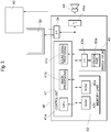
- Fig. 3 is a block diagram of hardware of the dart game apparatus 10.
- the dart game apparatus 10 includes a control circuit 40.
- the control circuit 40 is constituted of a control unit 41, a memory unit 42 and an operation input unit 43.
- the control unit 41 includes a CPU 41a that controls the entire system, an image processor 41b that performs image processing (e.g. processing of display position and size) of the image to be displayed on the screen, and a sound signal processing processor 41c that generates sound.
- the memory unit 42 is constituted of a ROM 42a in which programs and data used for the control unit 41 are stored, and a RAM 42b that temporarily stores various data in mid-game.
- an operation panel 43a In the operation input unit 43, an operation panel 43a, where various operation signals of a coin switch to detect the game payment, a select switch to select a game mode, a start switch and the like are inputted, is connected to the control unit 41 and the memory unit 42 via an interface 43b.
- the CPU 41a When the power is turned ON, the CPU 41a reads a game program according to a boot program in the ROM 42a, and causes the image processor 41b and the sound signal processing processor 41c to read and process the image and sound data stored in the ROM 42a, and outputs the image signals and sound signals to the display device 30 and an acoustic device 44 via the interfaces 3a and 44a respectively.
- the CPU 41a controls the progress of the dirt game according to the game program read from the ROM 42a, and progresses the game in the game mode desired by the player based on a coin entry signal from the operation input unit 43 and the input signals from the select switch and start switch.
- the player plays a game by throwing a dart D aiming at a target on the dart board 12 from a position that is distant from the dart game apparatus 10 by a predetermined distance, so that the dart D hits the board face 20A of the dart board 12.
- the dart D which the player threw aiming at the target on the board face 20A, hits the board face 20A, the dart D interrupts the light L, thereby the brightness of the light L directed to the photo-sensors S changes, and at least two photo-sensors S detect the change in the brightness of the light.
- These detection signals are sent to the control unit 41, and based on the brightness of the lights detected by the two photo-sensors S, and the CPU 41a specifies the brightness of the light caused by the dart D ("peak” or "shade of dart D"), specifies the direction of the shade of the dart D as angles ⁇ and ⁇ , for example, and calculates the hit position of the dart D by triangulation using the angles ⁇ and ⁇ .
- the CPU 41a reads a score, which corresponds to the calculated position, from a table stored in the ROM 42a, and causes the image processor 41b to display the change in the image of the target and the score on the display device 30, and also causes the sound signal processing processor 41c to generate a sound indicating a score increase, and outputs the sound from the acoustic device 44.
- the control circuit 40 uses the detection signals received from the photo-sensors S, calculates the hit position, adds up the score, and outputs the sound.
- the hit position of a dart D, score information, number of darts D that hit, a number of rounds and the like are sequentially stored in the RAM 42b, and the game progresses while outputting images and sounds based on this data.
- the image processor 41b Based on the arithmetic operation result of the program, the image processor 41b writes the image data to the RAM 42b.
- the written image data is sent to the display device 30 via the interface (I/F) circuit 3a. Further, the sound data that is outputted from the sound signal processing processor 41c is also sent to the acoustic device 44 via the interface (I/F) circuit 44a.
- a logical formula to determine a number of photo-sensors S which can calculate each position of all n number of darts D that hit the board face 20A of the dart board 12, will be described.
- one player normally throws three darts D sequentially, collects the darts D after all three darts are thrown, then another player takes their turn.
- four or more (especially four) darts D may be thrown (e.g. in the case of determining the turn of the players to throw darts).
- the above mentioned "n" is 3 or more (n ⁇ 3).
- Fig. 4 is a diagram depicting a case of calculating each hit position of three darts D (D1, D2, D3) when three photo-sensors S (S1, S2, S3) are disposed on the dart board 12 at equal intervals.
- the dart D3 of the third throw hit an intersection between a line connecting the photo-sensor S1 and the dart D1 of the first throw, and a line connecting the photo-sensor S2 and the dart D2 of the second throw, the shade of the dart D3, which overlaps with the shade of the dart D1 and the shade of the dart D2, cannot be detected by the photo-sensor S1 and the photo-sensor S2, but can be detected only by the photo-sensor S3. As a consequence, the position of the dart D3 cannot be calculated by triangulation.
- the dart D1 of the first throw and the dart D2 of the second throw hit the line connecting the photo-sensor S1 and the photo-sensor S2 respectively, for example, unlike the positions of the darts D illustrated in Fig. 4 , the shade of the dart D2 of the second throw can be detected only by the photo-sensor S3. As a consequence, the position of the dart D2 cannot be calculated by triangulation.
- Fig. 5 is a diagram depicting a case of calculating each hit position of three darts D (D1, D2, D3) when four photo-sensors S (S1, S2, S3, S4) are disposed on the dart board 12 at equal intervals.
- the dart D1 of the first throw hits the line connecting the photo-sensors S2 and S4
- the dart D2 of the second throw hits the line connecting the photo-sensors S1 and S3
- the dart D3 of the third throw hits the intersection of the above two lines
- the shade of the dart D3 of the third throw which overlaps with the shades of the dart D1 and the dart D2
- the positions of the darts D cannot be calculated by triangulation.
- Fig. 6 is a diagram depicting a case of calculating each hit position of three dots D (D1, D2, D3) when five photo-sensors S (S1, S2, S3, S4, S5) are disposed on the dart board 12 at equal intervals.
- the dart D1 of the first throw hits the line connecting the photo-sensors S2 and S4
- the dart D2 of the second throw hits the line connecting the photo-sensors S3 and S5
- the dart D3 of the third throw hits the intersection of the above two lines
- the shade of the dart D3 of the third throw which overlaps with the shades of the dart D1 and the dart D2 cannot be detected by the photo-sensors S2, S3, S4 and S5, but can be detected only by the photo-sensor S1.
- the position of the dart D3 of the third throw is in a region near the intersection of the line connecting S2 and S4 and the line connecting S3 and S5, but the precise position in the region cannot be recognized.
- the positions of the dart D1 of the first throw and the dart D2 of the second throw can be calculated by triangulation. Therefore each position of all the darts D cannot be calculated if the five photo-sensors S are used.
- Fig. 7 is a diagram depicting a case of calculating each hit position of three darts D (D1, D2, D3) when six photo-sensors S (S1, S2, S3, S4, S5, S6) are disposed on the dart board 12 at equal intervals.
- the shade of the dart D3 of the third throw can be detected by the two photo-sensors S1 and S4.
- the positions of the darts D1 to D3 can be calculated by triangulation. Therefore each position of all the darts D can be calculated if the six photo-sensors S are used.
- the dart D1 of the first throw hits the line connecting two photo-sensors S and the dart D2 of the second throw hits the same line, the shade of the dart D2, which overlaps with the shade of the dart D1 of the first throw (hidden by shade), cannot be detected by these two photo-sensors S at both ends of this line.
- the dart D of the first throw makes it impossible for two photo-sensors S to accurately detect the shade of the dart D of a subsequent throw.
- two photo-sensors S are required, that is, in order to detect the dart of the second throw without fail after the dart of the first throw hits a line connecting two photo-sensors S, four photo-sensors S are required. Further, in order to detect the dart of the third throw without fail after the dart of the second throw hits the line connecting the photo-sensors S, six photo-sensors S are required.
- n number of darts D which are successively thrown is four, and the three darts D thereof hit lines connecting mutually different photo-sensors S at points close to each other, two more photo-sensors S are required to detect the dart of the fourth throw without fail, in addition to the six photo-sensors S. This means that a total of eight photo-sensors S are required (not illustrated).
- a number of required photo-sensors S is determined by the theoretical formula 2 ⁇ n (1 ⁇ n).
- Fig. 8 is a diagram depicting a case of calculating each hit position of five darts D (D1 to D5) when the ten photo-sensors S (S1 to S10) are disposed on the dart board 12 at equal intervals.
- the shade of the dart D5 which overlaps with a shade of any one of the darts D1 to D4 (hidden by shade), cannot be detected by any of the photo-sensors S1 to S10.
- the shade of the dart D5 overlaps with a shade of any one of the darts D1 to D4 (hidden by shade), and cannot be detected by any of the photo-sensors S.
- n number of darts D to be thrown is five, the shade of the dart D of the fifth throw may not be detected in some cases, even if the number of photo-sensors S is increased, that is, a number of darts D of which positions can be detected and calculated is four at the maximum (n ⁇ 4).
- Embodiment 1 a dart game in which each player throws one or two darts in one round is not assumed, therefore an n number of darts D that are successively thrown in one round is three or four, and a number of photo-sensors S is six or eight, based on the theoretical formula 2 ⁇ n.
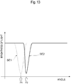
- Fig. 9A to Fig. 9C are graphs depicting a change in the brightness of the light detected by a photo-sensor S, where Fig. 9A is an example of a graph depicting the brightness of light detected by the photo-sensor S when the dart D of the first throw hits, Fig. 9B is an example of a graph depicting the brightness of light detected by the photo-sensor S when the dart D of the second throw successively hits after the first throw, and Fig. 9C is an example of a graph depicting the brightness of light when the photo-sensor S performed the difference processing of the brightness of light after the dart D of the second throw hits.
- the photo-sensor S is constituted of a plurality of image pickup elements to implement a required resolution, and each image pickup element performs photoelectric conversion from the brightness of the light into a charge amount, sequentially reads the charge amount, and converts the charge amount into an electric signal.
- each image pickup element performs photoelectric conversion from the brightness of the light into a charge amount, sequentially reads the charge amount, and converts the charge amount into an electric signal.
- the ordinate indicates the brightness of the light L measured by the photo-sensor S
- the abscissa indicates the position (angle) of the image pickup element that is sequentially read by the photo-sensor S, whereby the angle of the generated shade viewed from the photo-sensor S is known.
- the brightness of the light detected by the photo-sensor S includes a peak at which the brightness of the light drops. This peak indicates the shade of the dart D.
- the position of the dart D is calculated by triangulation based on the angle indicated by the arrow in Fig. 9A , at which the center line O of the width of the peak is located.
- the dart D of the second throw hits right next to the dart D of the first throw, as illustrated in Fig. 2 .
- the peak of the dart D of the second throw overlaps with the peak of the dart D of the first throw, and only one wide peak is detected, as illustrated in Fig. 9B .
- the angle indicated by the arrow in Fig. 9B at which the center line O1 of the width of the peak is located, is regarded as the angle of the dart D of the second throw, and the position of the dart D of the second throw is calculated based on this angle, an error is generated between the calculated position and the actual position of the dart D of the second throw.
- Embodiment 1 when a dart D hits the dart board 12, the CPU 41a stores the brightness of the light detected by the photo-sensor S in the RAM 42b as reference. Then if the next dart D hits the dart board 12 as indicated in Fig. 9C , the CPU 41a calculates the difference between this brightness of the light detected by the photo-sensor S and the stored brightness of the light. This difference is a peak (shade) of only the next dart D, hence the CPU 41a regards the angle indicated by the arrow in Fig. 9C , at which the center line of the width of this peak is located, as the angle of the dart D of the second throw, and calculates the hit position of the dart D of the second throw based on this angle. Thereby the generation of error between the calculated position and the actual position of the dart D of the second throw can be prevented.
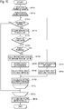
- Fig. 10 is a flow chart depicting a processing flow of the CPU 41a based on the game program that is executed by the dart game apparatus 10 according to Embodiment 1 of the present invention.
- the CPU 41a repeats the processing in step SP12 to step SP34 for a number of players that will play the dart game.
- n 3
- n 3
- the CPU 41a determines whether the change button was pressed. The CPU 41a advances to the processing in step SP36 if the result is Yes, or to step SP16 if No.
- the CPU 41a acquires a respective detection signal from six photo-sensors S, that is, the brightness of the light detected by each photo-sensor S. Then the CPU 41a advances to the processing in step SP18.
- the CPU 41a determines whether a dart D was thrown based on the brightness of light of each photo-sensor S. In concrete terms, the CPU 41a determines whether brightness changed in at least two lights, out of the lights of each photo-sensor S, and determines that the dart D was thrown (Yes) if the brightness changed in the at least two lights, or determines that the dart D was not thrown (No) if the brightness did not change in the at least two lights. If Yes, the CPU 41a increases the total number of darts D that were thrown and advances to the processing in step SP20, and if No, the CPU 41a returns to the processing in step SP14.
- the CPU 41a determines whether the dart D is the dart of the first throw by a player. The CPU 41a advances to the processing in step SP22 if Yes, or to the processing in step SP26 if No.
- the CPU 41a digitizes the brightness of each light and stores the brightness in the RAM 42b. Then the CPU 41a advances to the processing in step SP24.
- the CPU 41a calculates the position of the dart D by triangulation, based on the brightness of each light, particularly based on the brightness of the light generated by the dart D (shade of the dart D) out of the brightness of at least two lights that changed. Then the CPU 41a advances to the processing in step SP32.
- the CPU 41a calculates the difference between the brightness of each light detected by the photo-sensors S this time (brightness of light this time) and the brightness of each light detected by the photo-sensors S the last time (brightness of light last time) respectively, as indicated in Fig. 9C , for example. Then the CPU 41a advances to the processing in step SP28.
- the CPU 41a stores each difference in the RAM 42b. Then the CPU 41a advances to the processing in step SP30.
- the CPU 41a calculates the position of the dart D by triangulation based on each difference, particularly based on the difference of the brightness of the light caused by the dart D out of the brightness of at least two lights that changed. Then the CPU 41a advances to the processing in step SP32.
- the CPU 41a calculates the score based on the calculated position of the dart D and stores it in the RAM 42b in association with the player, whereby the player is provided with their score.
- the CPU 41a also makes a performance of the scoring based on the calculated score, such as reproducing an image on the display device 30 or outputting a sound from the acoustic device 44. Then the CPU 41a advances to the processing in step SP34.
- the CPU 41a returns to the processing in step SP12 until the processing in step SP14 to step SP32 are repeatedly performed for all the n number of darts D respectively, and advances to the processing in step SP36 when the repeat of the processing ends.
- the CPU 41a returns to the processing in step SP10 until the processing in step SP12 to step SP34 are repeatedly performed for a number of players, and advances to the processing in SP38 when the repeat of the processing end.
- the CPU 41a calculates the total score for each player, and determines the winner and the loser among the players based on each calculated total score. Further, based on the determination of the winner / loser, the CPU 41a makes a performance of the determination, such as reproducing an image on the display device 30 or outputting a sound from the acoustic device 44.
- the retro-reflector 24 is also provided, hence the light L emitted by the light source LS can be reflected back toward the light source LS, and the reflected light can be utilized to detect the shade of the dart D. Since the retro-reflector 24 functions like a light source LS as just described, a number of light sources LS can be kept to a minimum. If the number of light sources LS can be kept to a minimum, the manufacturing cost of the dart game apparatus 10 can be kept to a minimum as well.
- the hit position of the dart D is calculated based on the difference of the brightness of the light this time and the brightness of the light last time, hence even if two darts D hit positions close to each other, as illustrated in Fig. 2 , the positions of the darts D can be accurately calculated.
- Embodiment 2 is different from Embodiment 1 in terms of the position calculation processing of the CPU 41a, such as calculating an inclination of a dart D with respect to the dart board 12, and calculating the hit position of the dart D based on the determined inclination.
- the configuration of the dart game apparatus according to Embodiment 2 is the same as the dart game apparatus 10 according to Embodiment 1, except for the configuration of the retro-reflector 24 to calculate the inclination and the configuration of the photo-sensors S.
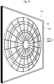
- Fig. 11 is a perspective view of the dart board 12A of the dart game apparatus according to Embodiment 2.
- the dart board 12A includes the retro-reflector 24.
- the retro-reflector 24 includes two reflectors 24A and 24B, which are disposed next to each other with a space in the board thickness direction of the dart board 12A.
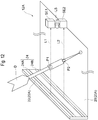
- Fig. 12 is a diagram depicting a configuration of the dart board 12A illustrated in Fig. 11 .
- two long and thin reflectors 24A and 24B exist on the inner wall 22A of the frame 22 in the circumferential direction of the board main body 20 of the dart board 12A.
- Photo-sensors SE1 and SE2 are disposed on both ends of the light sources S in the board thickness direction of the dart board 12A. In other words, two stages of the photo-sensors SE1 and SE2 are disposed in the board thickness direction. This combination of the photo-sensors SE1 and SE2 is disposed at six locations on the dart board 12A at equal intervals (not illustrated), and as a result, a total of twelve photo-sensors S are disposed two-dimensionally.
- the light emitted from the light source LS is reflected back by the reflectors 24A and 24B toward the light source LS, and is separated into two lights (light along the optical axis L1 and light along the optical axis L2), and these lights pass along the board face 20A of the dart board 12A at different heights from the board face 20A of the dart board 12A in the board thickness direction.
- the brightness of each passed light is detected by the photo-sensors SE1 and SE2.
- the photo-sensor SE1 detects the brightness of the light along the optical axis L1
- the photo-sensor SE2 detects the brightness of the light along the optical axis L2.
- the photo-sensors SE1 and SE2 can detect the shades of this one dart D respectively at two positions P1 and P2, where the distance (height) from the board face 20A is different.
- the CPU 41a acquires the angles of the shades (peaks) at the two positions P1 and P2 of the dart D, based on the brightness of the lights along the optical axes L1 and L2 respectively, which are outputted from the photo-sensors SE1 and SE2, and calculates the two positions P1 and P2 of the dart D based on these angles. Then the CPU 41a calculates the inclination of the dart D with respect to the dart board 12A, based on the calculated two positions P1 and P2 of the dart D.
- the CPU 41a calculates the hit position of the tip of the dart D.
- the method of calculating the position of the tip is not especially limited, but as shown in Fig. 14 , for example, the CPU 41a may calculate the coordinates of an intersection P3 between a virtual line l1 based on the calculated inclination and the board face 20A, and determine the coordinates of this point as the hit position of the dart D.
- the dart D is a soft dart of which tip portion is made of resin
- this tip portion may be bent for such reasons as the impact of hitting the board face 20A, the influence of the weight of the dart, and the contact with an adjacent dart D.
- the coordinates of the intersection P3 between the virtual line l1 of the inclination of the dart D and the board face 20A are determined as the hit position of the dart D, an error from the actual hit position may be generated.
- a position closer to the rear end of the dart D compared with the position of the intersection P1 between the virtual line l1 of the inclination and the board face 20A, that is, a position closer to the optical axes L1 and L2, is determined as the hit position of the dart D.
- the length of the tip portion of the dart D that enters the hole is known in advance, hence the position P4 determined by subtracting the length of the tip portion from the position of the intersection P3 may be regarded as the position closer to the optical axes L1 and L2, as illustrated in Fig. 14 .
- the characteristic of the dart D changes depending on the material, thickness, bending rigidity of the material and the like of the dart. Further, the tip portion of the dart D is often replaced by the player, so the thickness, bending rigidity of the material and the like the tip position of the dart D may vary. Therefore, the CPU 41a may calculate the curvature based on the average characteristic of the thickness of the tip portion of the dart, bending rigidity of the material and the like, and determine the hit position of the dart D based on the calculated curvature.
- the dart D hits the board face 20A at a specific location so that the dart D is inclined by 90° to 40°.
- a 90° inclination means that the inclination of the dart D is vertical to the board face 20A.
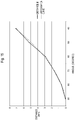
- Table 1 indicates the relationship between the angle of the dart D and the distance d.
- Fig. 15 is a graph depicting the relationship between the angle of the dart D and the distance d.
- the approximation curve indicated in Fig. 15 is a quadratic curve.
- the distance d with respect to the angle of the dart D, can be approximated by a quadratic curve, where the ordinate is the distance d and the abscissa is the angle of the dart D.
- the distance d depends on the thickness and rigidity of the material of the tip portion of the dart D to be used, hence the quadratic curve (approximation formula) is determined in accordance with the environment in which the dart game apparatus is used.
- the quadratic curve is determined in accordance with the environment in which the dart game apparatus is used.
- the retro-reflector 24 includes two reflectors 24A and 24B, which are disposed next to each other with a space in the board thickness direction of the dart board 12, and the light emitted from the light source LS can be separated into two lights (light along the optical axis L1 and light along the optical axis L2). By using the brightness of these two lights, the shades of the dart D at positions, of which distances from the board face 20A are different, can be acquired.
- the CPU 41a calculates the inclination of the dart D with respect to the dart board 12 based on the brightness of the two lights, and calculates the hit position of the dart D based on the calculated inclination, hence compared with the case of not calculating the inclination, the position of the dart D can be calculated more accurately.
- the CPU 41a calculates the position P4, which is on the rear side of the dart D, compared with the position of the intersection P3 between the virtual line l1 of the dart D along the inclination of the dart D and the board face 20A of the dart board 12, hence the position of the dart D, considering the bending of the dart D, can be calculated more accurately.
- the present invention is not limited to the above embodiments. In other words, modifications of the above embodiments, which a person skilled in the art can perform by appropriately changing the design, are included in the scope of the present invention, as long as the characteristics of the present invention are included. Further, each element of the above-mentioned embodiments may be combined if technically possible, and these combinations are also included in the scope of the present invention, as long as the characteristics of the present invention are included.
- Embodiment 1 a case of disposing the retro-reflector 24 was described, but the retro-reflector 24 may be omitted.
- the position of the dart D may be detected in the same manner as Embodiment 1 by disposing a plurality of light sources LS so as to surround the dart board 12, as illustrated in Fig. 16 , for example.
- Embodiment 2 a case of disposing the two reflectors 24A and 24B, to acquire the two optical axes L1 and L2, was described, but the light sources LS which are stacked in two levels in the board thickness direction may be disposed instead, as illustrated in Fig. 17 , for example.
- Embodiment 2 a case of disposing the two photo-sensors SE1 and SE2 in the board thickness direction was described, but a photo-sensor SE3, which has a width to receive the light along the optical axis L1 and the light along the optical axis L2 respectively, may be disposed instead, as illustrated in Fig. 17 , for example.
- Embodiment 2 a case of the CPU 41a calculating the inclination of the dart D with respect to the dart board 12, based on the peaks at two locations of the dart D, was described, but the following additional processing may be added to this calculation. That is, in the case where a new dart D hits the dart board 12A and the brightness of one light detected by the photo-sensor SE1 or SE2 has a plurality of peaks (shades of the dart D),CPU 41a may specify the current peak of the previous dart out of the plurality of peaks, based on the peaks of the previous dart D in the past stored in the RAM 42b, and calculate the inclination of the dart D based on the peaks other than the specified current peak of the previous dart.
- a peak based on the position P12 on the rear end side of the previous dart D10 exists in the brightness of the light along the optical axis L1 detected by the photo-sensor SE1, besides the peak based on the position P13 of the new dart D11, even if the difference of the brightness from the previous time is determined.
- a peak based on the position P11 on the rear end side of the previous dart D10 exists in the brightness of the light long the optical axis L2 detected by the photo-sensor SE2, besides the peak based on the position P14 of the new dart D11, even if the difference of the brightness from the previous time is determined.
- the CPU 41a specifies the peak at the position P11 and the peak at the position P12 of the previous dart D10, out of a plurality of peaks, based on the peaks of the previous dart D10 in the past, and calculates the inclination of the new dart D based on the peaks other than the specified peaks, that is, based on the peak at the position P13 and the peak at the position P14. Then the current position P15 can be calculated.
Landscapes
- Engineering & Computer Science (AREA)
- General Engineering & Computer Science (AREA)
- Mechanical Engineering (AREA)
- Health & Medical Sciences (AREA)
- General Health & Medical Sciences (AREA)
- Physical Education & Sports Medicine (AREA)
- Aiming, Guidance, Guns With A Light Source, Armor, Camouflage, And Targets (AREA)
- Vending Machines For Individual Products (AREA)
- Control Of Vending Devices And Auxiliary Devices For Vending Devices (AREA)
Applications Claiming Priority (2)
| Application Number | Priority Date | Filing Date | Title |
|---|---|---|---|
| JP2017148514A JP6966677B2 (ja) | 2017-07-31 | 2017-07-31 | ダーツゲーム装置 |
| PCT/JP2018/028503 WO2019026856A1 (ja) | 2017-07-31 | 2018-07-30 | ダーツゲーム装置 |
Publications (3)
| Publication Number | Publication Date |
|---|---|
| EP3663700A1 true EP3663700A1 (de) | 2020-06-10 |
| EP3663700A4 EP3663700A4 (de) | 2021-04-28 |
| EP3663700B1 EP3663700B1 (de) | 2026-02-25 |
Family
ID=65233847
Family Applications (1)
| Application Number | Title | Priority Date | Filing Date |
|---|---|---|---|
| EP18842106.9A Active EP3663700B1 (de) | 2017-07-31 | 2018-07-30 | Darts-spielvorrichtung |
Country Status (7)
| Country | Link |
|---|---|
| US (1) | US11112220B2 (de) |
| EP (1) | EP3663700B1 (de) |
| JP (1) | JP6966677B2 (de) |
| CN (1) | CN110959098B (de) |
| SG (1) | SG11202000355SA (de) |
| TW (1) | TWI784033B (de) |
| WO (1) | WO2019026856A1 (de) |
Families Citing this family (7)
| Publication number | Priority date | Publication date | Assignee | Title |
|---|---|---|---|---|
| WO2021021123A1 (en) * | 2019-07-30 | 2021-02-04 | Archery Intelligence, LLC | Archery tuning system |
| CN114935282A (zh) * | 2022-06-10 | 2022-08-23 | 河海大学 | 一种用于飞镖训练的语音报分系统 |
| KR102548105B1 (ko) * | 2022-08-16 | 2023-06-27 | 주식회사 피닉스다트 | 다트핀 히트 위치 식별 방법, 컴퓨터 프로그램, 및 장치 |
| USD1001894S1 (en) * | 2023-03-29 | 2023-10-17 | Guochao Chen | Inflatable dart board |
| USD1006880S1 (en) * | 2023-03-29 | 2023-12-05 | Guochao Chen | Inflatable dart board |
| USD1057829S1 (en) * | 2024-05-31 | 2025-01-14 | Bo Huang | Inflatable game target |
| USD1118753S1 (en) * | 2025-05-06 | 2026-03-17 | Brett Jackowski | Inflatable bullseye |
Family Cites Families (12)
| Publication number | Priority date | Publication date | Assignee | Title |
|---|---|---|---|---|
| US4789932A (en) * | 1984-09-21 | 1988-12-06 | Austin T. Musselman | Apparatus and method for automatically scoring a dart game |
| DE19800441C2 (de) * | 1997-01-20 | 2002-10-31 | Domotec Systemtechnik Gmbh | Vorrichtung zum Ermitteln des Auftreffpunktes von Wurfpfeilen auf einer Zielscheibe |
| US6717684B1 (en) * | 2000-06-09 | 2004-04-06 | Dynetics, Inc. | Target scoring system |
| EP1832836B8 (de) | 2004-12-31 | 2014-01-08 | Sega Corporation | Dartsspielvorrichtung |
| KR101032407B1 (ko) * | 2008-09-24 | 2011-05-03 | 주식회사 지닌 | 발광 소자 및 수광 소자를 이용한 다트 게임의 스코어링 장치 및 방법 |
| KR101517348B1 (ko) * | 2013-01-07 | 2015-05-04 | 주식회사 홍인터내셔날 | 다트 게임을 촬영하기 위한 촬영 장치를 포함하는 다트 게임 장치 |
| WO2016203194A1 (en) * | 2015-06-18 | 2016-12-22 | Flight Path Ip Limited | Automatic dartboard scoring system |
| KR101627264B1 (ko) * | 2015-08-10 | 2016-06-03 | 주식회사 홍인터내셔날 | 복수의 카메라를 구비한 다트 게임 장치 및 컴퓨터-판독가능 매체에 저장된 컴퓨터 프로그램 |
| CN105180721B (zh) * | 2015-08-11 | 2017-10-31 | 中国船舶重工集团公司第七0九研究所 | 自动报靶及测速装置及其定位测速方法 |
| CN205699365U (zh) * | 2016-04-14 | 2016-11-23 | 薛梓瑗 | 飞镖游戏设备 |
| CN106323097A (zh) * | 2016-08-25 | 2017-01-11 | 中国人民解放军总参谋部第六十研究所 | 一种共面三边感光的光电靶装置 |
| CN106595396A (zh) * | 2016-12-15 | 2017-04-26 | 深圳分汇科技有限公司 | 一种红外电子计分飞镖靶 |
-
2017
- 2017-07-31 JP JP2017148514A patent/JP6966677B2/ja active Active
-
2018
- 2018-07-30 SG SG11202000355SA patent/SG11202000355SA/en unknown
- 2018-07-30 CN CN201880048455.7A patent/CN110959098B/zh active Active
- 2018-07-30 WO PCT/JP2018/028503 patent/WO2019026856A1/ja not_active Ceased
- 2018-07-30 US US16/631,108 patent/US11112220B2/en active Active
- 2018-07-30 EP EP18842106.9A patent/EP3663700B1/de active Active
- 2018-07-31 TW TW107126482A patent/TWI784033B/zh active
Also Published As
| Publication number | Publication date |
|---|---|
| TWI784033B (zh) | 2022-11-21 |
| TW201919742A (zh) | 2019-06-01 |
| WO2019026856A1 (ja) | 2019-02-07 |
| EP3663700B1 (de) | 2026-02-25 |
| SG11202000355SA (en) | 2020-02-27 |
| JP2019027703A (ja) | 2019-02-21 |
| CN110959098B (zh) | 2022-07-15 |
| JP6966677B2 (ja) | 2021-11-17 |
| CN110959098A (zh) | 2020-04-03 |
| US11112220B2 (en) | 2021-09-07 |
| US20200132419A1 (en) | 2020-04-30 |
| EP3663700A4 (de) | 2021-04-28 |
Similar Documents
| Publication | Publication Date | Title |
|---|---|---|
| EP3663700B1 (de) | Darts-spielvorrichtung | |
| JP4682986B2 (ja) | ダーツゲーム装置 | |
| CN101198383B (zh) | 位置检测系统 | |
| EP0182397B1 (de) | Gerät und Methode zur automatischen Resultatauswertung eines Wurfpfeilspiels | |
| JP5016049B2 (ja) | 対象の方向性の決定 | |
| KR101475120B1 (ko) | 빔프로젝트를 구비한 다트 게임 장치 | |
| US20060105842A1 (en) | Shooting game machine and method for performing it | |
| WO1998017361A1 (fr) | Dispositif de commande de jeux et support de stockage d'informations | |
| WO2001000285A1 (en) | Method and apparatus for a portable golf training system with an optical sensor net | |
| US20100178967A1 (en) | Shooting game processing method | |
| JP2023129676A (ja) | 標的システム、およびプログラム | |
| WO2019107146A1 (ja) | ダーツゲーム装置、ダーツ不正判定方法及びプログラム | |
| KR20140062611A (ko) | 디스플레이를 구비한 다트 게임 장치 | |
| CN110945313B (zh) | 飞镖游戏装置以及存储介质 | |
| US20080199047A1 (en) | Indication position calculation system, indicator for indication position calculation system, game system, and indication position calculation method | |
| US20140024470A1 (en) | Golf analysis system with frameless optical sensor net | |
| KR101032407B1 (ko) | 발광 소자 및 수광 소자를 이용한 다트 게임의 스코어링 장치 및 방법 | |
| HK40017103A (en) | Darts game device | |
| HK40017103B (en) | Darts game device | |
| WO2007001051A1 (ja) | ネットワークゲームシステム、ゲーム装置、ゲーム装置の制御方法及び情報記憶媒体 | |
| JPH07225100A (ja) | 電子式射的用標的 | |
| TWI754769B (zh) | 飛鏢遊戲裝置及方法 | |
| JP3496064B2 (ja) | 国際射撃競技用高性能光線銃の電子標的装置 | |
| US20160231424A1 (en) | Laser distance measure | |
| WO2018106179A1 (en) | Method for calibrating a shooting target system, method for determing an impact position on a shooting target, and a shooting target system |
Legal Events
| Date | Code | Title | Description |
|---|---|---|---|
| STAA | Information on the status of an ep patent application or granted ep patent |
Free format text: STATUS: THE INTERNATIONAL PUBLICATION HAS BEEN MADE |
|
| PUAI | Public reference made under article 153(3) epc to a published international application that has entered the european phase |
Free format text: ORIGINAL CODE: 0009012 |
|
| STAA | Information on the status of an ep patent application or granted ep patent |
Free format text: STATUS: REQUEST FOR EXAMINATION WAS MADE |
|
| 17P | Request for examination filed |
Effective date: 20200123 |
|
| AK | Designated contracting states |
Kind code of ref document: A1 Designated state(s): AL AT BE BG CH CY CZ DE DK EE ES FI FR GB GR HR HU IE IS IT LI LT LU LV MC MK MT NL NO PL PT RO RS SE SI SK SM TR |
|
| AX | Request for extension of the european patent |
Extension state: BA ME |
|
| DAV | Request for validation of the european patent (deleted) | ||
| DAX | Request for extension of the european patent (deleted) | ||
| A4 | Supplementary search report drawn up and despatched |
Effective date: 20210330 |
|
| RIC1 | Information provided on ipc code assigned before grant |
Ipc: F41J 3/02 20060101AFI20210324BHEP Ipc: A63B 65/02 20060101ALI20210324BHEP Ipc: F41J 5/02 20060101ALI20210324BHEP |
|
| STAA | Information on the status of an ep patent application or granted ep patent |
Free format text: STATUS: EXAMINATION IS IN PROGRESS |
|
| 17Q | First examination report despatched |
Effective date: 20231106 |
|
| GRAP | Despatch of communication of intention to grant a patent |
Free format text: ORIGINAL CODE: EPIDOSNIGR1 |
|
| STAA | Information on the status of an ep patent application or granted ep patent |
Free format text: STATUS: GRANT OF PATENT IS INTENDED |
|
| INTG | Intention to grant announced |
Effective date: 20251112 |
|
| GRAS | Grant fee paid |
Free format text: ORIGINAL CODE: EPIDOSNIGR3 |
|
| GRAA | (expected) grant |
Free format text: ORIGINAL CODE: 0009210 |
|
| STAA | Information on the status of an ep patent application or granted ep patent |
Free format text: STATUS: THE PATENT HAS BEEN GRANTED |
|
| AK | Designated contracting states |
Kind code of ref document: B1 Designated state(s): AL AT BE BG CH CY CZ DE DK EE ES FI FR GB GR HR HU IE IS IT LI LT LU LV MC MK MT NL NO PL PT RO RS SE SI SK SM TR |
|
| REG | Reference to a national code |
Ref country code: CH Ref legal event code: F10 Free format text: ST27 STATUS EVENT CODE: U-0-0-F10-F00 (AS PROVIDED BY THE NATIONAL OFFICE) Effective date: 20260225 Ref country code: GB Ref legal event code: FG4D |
|
| REG | Reference to a national code |
Ref country code: DE Ref legal event code: R096 Ref document number: 602018089434 Country of ref document: DE |
|
| REG | Reference to a national code |
Ref country code: IE Ref legal event code: FG4D |