EP3663636B1 - Leuchte mit befestigungsvorrichtung zur mastmontage - Google Patents
Leuchte mit befestigungsvorrichtung zur mastmontage Download PDFInfo
- Publication number
- EP3663636B1 EP3663636B1 EP19212408.9A EP19212408A EP3663636B1 EP 3663636 B1 EP3663636 B1 EP 3663636B1 EP 19212408 A EP19212408 A EP 19212408A EP 3663636 B1 EP3663636 B1 EP 3663636B1
- Authority
- EP
- European Patent Office
- Prior art keywords
- mounting
- fastening
- luminaire
- axis
- rotation
- Prior art date
- Legal status (The legal status is an assumption and is not a legal conclusion. Google has not performed a legal analysis and makes no representation as to the accuracy of the status listed.)
- Active
Links
Images

Classifications
-
- F—MECHANICAL ENGINEERING; LIGHTING; HEATING; WEAPONS; BLASTING
- F21—LIGHTING
- F21V—FUNCTIONAL FEATURES OR DETAILS OF LIGHTING DEVICES OR SYSTEMS THEREOF; STRUCTURAL COMBINATIONS OF LIGHTING DEVICES WITH OTHER ARTICLES, NOT OTHERWISE PROVIDED FOR
- F21V21/00—Supporting, suspending, or attaching arrangements for lighting devices; Hand grips
- F21V21/10—Pendants, arms, or standards; Fixing lighting devices to pendants, arms, or standards
- F21V21/116—Fixing lighting devices to arms or standards
-
- F—MECHANICAL ENGINEERING; LIGHTING; HEATING; WEAPONS; BLASTING
- F21—LIGHTING
- F21S—NON-PORTABLE LIGHTING DEVICES; SYSTEMS THEREOF; VEHICLE LIGHTING DEVICES SPECIALLY ADAPTED FOR VEHICLE EXTERIORS
- F21S8/00—Lighting devices intended for fixed installation
- F21S8/08—Lighting devices intended for fixed installation with a standard
- F21S8/085—Lighting devices intended for fixed installation with a standard of high-built type, e.g. street light
- F21S8/086—Lighting devices intended for fixed installation with a standard of high-built type, e.g. street light with lighting device attached sideways of the standard, e.g. for roads and highways
-
- F—MECHANICAL ENGINEERING; LIGHTING; HEATING; WEAPONS; BLASTING
- F21—LIGHTING
- F21V—FUNCTIONAL FEATURES OR DETAILS OF LIGHTING DEVICES OR SYSTEMS THEREOF; STRUCTURAL COMBINATIONS OF LIGHTING DEVICES WITH OTHER ARTICLES, NOT OTHERWISE PROVIDED FOR
- F21V17/00—Fastening of component parts of lighting devices, e.g. shades, globes, refractors, reflectors, filters, screens, grids or protective cages
- F21V17/10—Fastening of component parts of lighting devices, e.g. shades, globes, refractors, reflectors, filters, screens, grids or protective cages characterised by specific fastening means or way of fastening
- F21V17/12—Fastening of component parts of lighting devices, e.g. shades, globes, refractors, reflectors, filters, screens, grids or protective cages characterised by specific fastening means or way of fastening by screwing
-
- F—MECHANICAL ENGINEERING; LIGHTING; HEATING; WEAPONS; BLASTING
- F21—LIGHTING
- F21V—FUNCTIONAL FEATURES OR DETAILS OF LIGHTING DEVICES OR SYSTEMS THEREOF; STRUCTURAL COMBINATIONS OF LIGHTING DEVICES WITH OTHER ARTICLES, NOT OTHERWISE PROVIDED FOR
- F21V21/00—Supporting, suspending, or attaching arrangements for lighting devices; Hand grips
- F21V21/14—Adjustable mountings
- F21V21/30—Pivoted housings or frames
Definitions
- the invention relates to a lamp with a fastening device for mounting on a component according to the preamble of claim 1.
- Generic lights are designed to be attached to a component, such as a wall or a lamp post.
- a component such as a wall or a lamp post.
- generic lights have a light housing with a light exit side, in which a light source is arranged, and a fastening device by means of which the light can be mounted on the component.
- a fastening device has at least two parts, namely a first fastening part and a second fastening part.
- the first fastening part serves to mount the fastening device on the component
- the second fastening part serves to ensure that the lamp housing can be connected to the first fastening part and thus to the component.
- the second fastening part is integrated in the lamp housing in one piece.
- the second attachment part is an element that is separate from the lamp housing and can be connected to it.
- the first fastening part has a mounting section which is suitable for receiving a pole spigot.
- this assembly section can then be designed in the manner of a hollow cylinder.
- the mounting section is designed in the manner of a plate that can be attached to a wall or a ceiling in a simple manner, for example using screws.
- the first and second fastening parts are designed to correspond to one another in such a way that they make it possible for the lamp housing to assume different angular positions relative to the component when it is fixed to the component.
- the first fastening part has a first fastening section, which has a first contact surface
- the second fastening part has a second fastening section, which has a second contact surface designed to correspond to the first contact surface.
- the first and second fastening parts can be rotated about an axis of rotation relative to one another over an angular range into different angular positions relative to one another, with the first and second contact surfaces bearing against one another in the different relative angular positions that can be set within the angular range, and the two fastening parts being fixed in position against one another are fixable.
- One of the fastening parts has at least one passage within its contact surface, through which a fastening means, for example a screw or a bolt with an eccentric device, is inserted in an intended operating position and is fixed to a fastening anchor provided on the other of the two fastening parts.
- a fastening means for example a screw or a bolt with an eccentric device
- the fastening anchor can be designed as an external thread for receiving the thread of a screw or as a seat for a holding part of the fastening means designed to correspond to the seat, so that, for example, latching or clamping between the holding part and seat can be realized.
- the person skilled in the art is familiar with common fastening means and common corresponding ones Fastening anchor known.
- a fastening means is inserted through the bushing, which is fixed to the fastening anchor provided on the other of the two fastening parts and which has a fastening head against one of the bushings surrounding curved surface portion, wherein the passage and / or the mounting anchor extends elongated in a direction perpendicular to the axis of rotation.
- fastening head of the fastening means it is of course necessary for the fastening head of the fastening means to be able to press against the surface section in all relative angular positions of the first and second fastening parts that can be set within the angular range when the fastening means is fixed to the fastening anchor of the other of the fastening parts. Because by pressing against the surface section of one fastening part, which of course takes place with a force direction towards the fastening anchor, the first fastening part is pressed with its first contact surface against the second contact surface of the second fastening part.
- the approaches known in the prior art require a very large-volume provision of fastening means, fastening anchors and/or surface section, as a result of which the design of the light fixture becomes large-volume overall, which is detrimental to the design of the light fixture.
- the approaches described in the prior art have the disadvantages described to a large extent.
- approaches known in the prior art are often difficult for the installer to handle when fixing the luminaire to a component.
- a lamp that has a fastening device by means of which a lamp housing of the lamp can assume different angular positions relative to a component of the lamp, displacement being possible about an axis of rotation over an angular range into different relative angular positions.
- the present invention is based on the object of at least partially eliminating at least one of the above-described disadvantages of generic luminaires.
- the invention proposes a lamp with the features of claim 1 .
- the lamp according to the invention has a lamp housing with a light exit side, in which a light source is arranged.
- the lamp according to the invention also has a fastening device which comprises a first fastening part and a second fastening part.
- the first attachment part has a mounting portion for mounting to a component, and the second attachment part is arranged on the lamp housing.
- the second fastening part can be fixed in a fixed position on the lamp housing or can be integrated in one piece in the lamp housing.
- the first fastening part has a first fastening section, which has a first contact surface
- the second fastening part has a second fastening section, which has a second contact surface designed to correspond to the first contact surface.
- the first and the second fastening part can be rotated relative to one another about an axis of rotation over an angular range in different angular positions relative to one another.
- the first and the second contact surface are in contact with one another and the two fastening parts can be fixed in a fixed position on one another.
- the two fastening parts are fixed in position to one another and are in a relative angular position previously determined by the fitter.
- One of the two fastening parts has at least one passage within its contact surface, and the other of the two fastening parts has a fastening anchor.
- the lamp according to the invention also comprises a fastening means which is inserted in the operating position through the passage of one of the two fastening parts and which is fixed to the fastening anchor of the other of the two fastening parts and which has a fastening head against a bushing surrounding it Surface section presses.
- the fastening head is encompassed by the fastening means.
- the bushing and/or the fastening anchor extends in a direction perpendicular to the axis of rotation.
- the feedthrough can be designed as a slot, for example the feedthrough can have several feedthrough sections arranged next to one another and possibly spaced apart perpendicularly to the axis of rotation, with a web provided by the surface section being provided between the feedthrough sections.
- the elongate passage is realized by a plurality of separate passage sections, in particular only discrete angular positions are possible between the two fastening parts, which are then predetermined by the various passage sections.
- the mounting anchor may also be either continuous and elongated perpendicular to the axis of rotation or may have discrete, spaced mounting anchor sections.
- the lamp according to the invention can have further features which are explained above in connection with lamps of the generic type.
- the surface section is curved
- the fastening head has a curved fastening surface on its side facing the surface section, with which it presses against the surface section in the operating position, which is curved in the same direction as the surface section.
- the fastening head presses against the surface section with a certain proportion of its fastening surface.
- This proportion of the fastening surface is particularly preferably at least 50 mm 2 , in particular at least 80 mm 2 .
- the amount of the area of this section varies of the mounting surface by less than 10%, in particular by less than 5%, in particular not at all, if the different angular positions are adjusted within the angular range and thus different operating positions are realized.
- the curved surface section whose curvature corresponds to the curvature of the fastening surface of the fastening head, particularly preferably extends over at least 70%, in particular at least 90% of the length of the passage perpendicular to the axis of rotation, in particular at least at one end of the passage perpendicular to the extension of the passage to the axis of rotation.
- both the surface section and the portion of the fastening surface with which the fastening head presses against the surface section in the operating position extend in any angular position within the angular range on both sides of the bushing, in relation to the direction of the axis of rotation, beyond the bushing a length along the direction of the axis of rotation which is at least 0.5 times, in particular at least 1 times, the width of the passage along the direction of the axis of rotation.
- the surface section extends in the direction of the axis of rotation on both sides of the passage over the entire length of the passage perpendicular to the axis of rotation over at least 0.5 times, in particular at least 1 times, the width of the passage in the direction of the axis of rotation .
- the surface section extends on both sides of the passage in relation to the direction perpendicular to the axis of rotation over the passage with a length that corresponds to at least 0.5 times, in particular at least 1 time, the width of the passage in the direction of the axis of rotation .
- the lamp according to the invention has significant advantages compared to lamps of the generic type.
- the fastening head can press against the surface section over the angular range with the largest possible surface and can thus fix the two fastening parts to one another with high contact pressure. After all, the contact pressure between the two fastening parts is applied by the fastening head, so that the surface with which the fastening head bears against the surface section represents the surface with which a force for generating the contact pressure between the two fastening parts can be generated.
- the installation of the lamp on a component can also be simplified, since a fitter can very easily align the mounting head in any adjustable angular position within the angular range relative to the surface section that it rests against the surface portion with a large area.
- the bushing is provided on the first attachment part and the attachment anchor is provided on the second attachment part.
- the passage is provided on the second attachment part and the attachment anchor on the first attachment part. If the leadthrough is provided in the first fastening part, the ability to mount the lamp on a component can be particularly simplified, since the fastening means or the fastening head of the fastening means can be easily accessible from the outside.
- the fastening anchor which is provided on the second fastening part, is particularly preferably designed in the manner of a blind hole so that water and other contaminants cannot penetrate the environment in the lamp housing can be prevented in a very simple manner.
- the fastening head can be arranged, for example, in the lamp housing, as a result of which it can be optically concealed in the lamp housing.
- a plurality of bushings offset from one another and a plurality of fastening anchors offset from one another can be provided, with one fastening anchor each being assigned to one bushing.
- all the passages can be provided on one of the fastening parts and all the fastening anchors on the other of the two fastening parts, or the various passages and the various fastening anchors can be provided partly on the first fastening part and partly on the second fastening part.
- the fastening surface and the surface section have a circular arc-shaped curvature about an axis of curvature running parallel to the axis of rotation.
- the arcuate curvature can ensure in a particularly reliable and simple manner that the fastening head always bears against the surface section in the operating position with an at least substantially equally large area in every possible relative angular position within the angular range.
- the fastening head rests with more than 70% of its fastening surface on the surface section, in particular with more than 90% its mounting surface.
- the mounting surface of the mounting head is the surface of the side of the mounting head that faces the surface portion in the operative position.
- the radius of curvature of the arcuate curvature deviates by less than 20%, in particular by less than 10%, from the length of an imaginary connecting line, which can be defined in any relative angular position within the angular range and which is perpendicular to the axis of rotation and perpendicular to the surface section strikes and one end is defined by the axis of rotation and the other end by the surface portion.
- the radius of curvature particularly preferably corresponds to the length of this imaginary line.
- the attachment surfaces and the surface portion have a spherical curvature. They therefore have the shape of a spherical segment.
- the configuration of the fastening surfaces and surface section in the form of a segment of a sphere has particular advantages. On the one hand, this can ensure, as explained with regard to the arcuate curvature, that the fastening head presses against the surface section with a large area in the operating position in any relative angular position within the angular range. On the other hand, the installation of the lamp on a component can be simplified even further.
- the fastening head can be aligned in any way relative to the surface section without significantly reducing the area with which the fastening head presses against the surface section in a specific relative angular position.
- the fastening head lies within the angular range with more than 70% of its Mounting surface on the surface portion, in particular with over 90% of its mounting surface.
- the radius of curvature of the spherical curvature particularly preferably deviates by less than 20%, in particular by less than 10%, from the length of an imaginary connecting line, which can be defined in any relative angular position within the angular range and which is perpendicular to the axis of rotation and perpendicular to the surface section strikes and one end is defined by the axis of rotation and the other end by the surface portion.
- the radius of curvature particularly preferably corresponds to the length of this imaginary line.
- a first guide section is provided on the fastening head, which corresponds to a second guide section, which is provided in the bushing or on the surface section for fixing a rotational position of the fastening head relative to the fastening part having the bushing, with a rotational position about a rotational axis is turned off, which runs perpendicular to the axis of rotation.
- the provision of such guide sections can simplify the assembly of the lamp even further and thereby ensure that the fastening head always presses against the surface section with a sufficiently large area in the operating position.
- the second guiding portion can be provided in the bushing such that it is provided by the bushing itself, the first guiding portion being a pin to be placed in the bushing to reach the operative position.
- the second guide section can be ensured via elevations of the surface section, between which the first guide section is to be arranged in order to reach the operating position.
- the first and second contact surfaces each have an upper side facing the other of the two contact surfaces, the envelope of which is a circular arc curved around the axis of rotation.
- the first and/or second contact surface can have indentations on their upper side facing the other of the two contact surfaces, which can be useful for setting discrete angular positions, the envelope of the indentations having the shape of a circular arc.
- the upper sides of the contact surfaces, with which the contact surfaces face each other and rest against one another in the operating position are each designed as a circular arc section.
- the cross-section of the contact surfaces perpendicular to the axis of rotation is taken into account.
- the fastener head includes a head portion integral with a bolt and a separate washer, the washer having the curved mounting surface on one side and the head portion abutting the opposite side of the washer.
- This embodiment can have the particular advantage that commercially available components, for example screws, can be used to implement the fastening means, whereas only the washer has to be specifically designed to implement the lamp according to the invention.
- the fastening means is particularly preferably designed such that it has a bolt which is connected in one piece to a head part, the head part forming at least part of the fastening head, and the bolt being inserted through the bushing in the operating position.
- this washer particularly preferably has a receptacle for receiving the head part, with the receptacle being designed in particular as a cylindrical recess in the side opposite the curved sides.
- This receptacle can, for example, provide guidance for the head part and, for example, contribute to mounting the lamp on a component that is as little visible as possible and, moreover, simple.
- the fastening means is particularly preferably designed as a screw, with a thread being provided in the other fastening part as a fastening anchor, into which the fastening means is screwed in the operating position in order to achieve the pressing of its fastening head against the surface section.
- two passages that are offset relative to one another along the axis of rotation are provided within the contact surface of one fastening part.
- two fastening anchors offset from one another along the axis of rotation are preferably provided in the other of the two fastening parts.
- the lamp has two fastening means, two bushings, two fastening anchors and two surface sections, one fastening means being assigned to one bushing, one fastening anchor and one surface section, and each combination of assigned fastening means, assigned bushing, assigned fastening anchor and assigned surface section in particular can be configured, as shown here using various exemplary embodiments with reference to a bushing, a fastening anchor Fasteners and a surface section explained.
- the two passages are particularly preferably spaced apart from one another along the axis of rotation by at least five times their width along the axis of rotation.
- the assembly section of the first fastening part is particularly preferably arranged at least in sections, in particular over at least 50%, in particular at least 805% of its extension along the axis of rotation between the two passages.
- the fastening device is suitable for setting at least two relative angular positions of the first and second fastening parts about the axis of rotation in relation to one another, with the two fastening parts being pivoted relative to one another around the axis of curvature by at least 10°, in particular at least 20°, starting from the first angular position, wherein in both angular positions the fastening head presses with more than 70%, in particular more than 80% of its fastening surface against the surface section surrounding the passage.
- the fastening device and the fastening means are particularly preferably designed in such a way that the angular range within which various angular positions can be set for the fastening part, in which they can be fixed in the operating position to one another, is at least 10°, in particular at least 20° around the axis of rotation.
- the contact surfaces of both fastening parts curve by at least 20° within a section along a direction perpendicular to the axis of rotation, with this section having an extension in this direction perpendicular to the axis of rotation that is less than 10 cm, in particular less than 7 cm.
- This section of the contact surfaces is therefore short and thus extends only over a short length perpendicular to the axis of rotation, whereas at the same time the contact surfaces with this section ensure a considerable degree of twistability relative to one another.
- the contact surfaces must have correspondingly small radii of curvature, in particular about an axis of curvature running parallel to the axis of rotation.
- the inventors have recognized that, based on the idea underlying the invention, such a design can be realized and it can be ensured that the fastening head presses against the surface section with a sufficiently large area in the operating position, specifically in different angular positions within the angular range.
- corresponding discretization devices are provided on the abutting contact surfaces, which are distributed over an angular range of at least 10°, in particular at least 20° around the axis of rotation on the two contact surfaces to ensure that the two fastening parts can be fixed to one another via their corresponding discretization devices in different positions angular positions to each other.
- Such discretization devices can be formed, for example, via the grids explained above.
- the discretization devices can, for example, be designed in such a way that one of the fastening parts has at least one elevation on its contact surface and the other of the fastening parts has at least one elevation on its contact surface Has depression, wherein elevation and depression are designed to correspond to each other, so that they can be engaged.
- the discretization devices are designed in such a way that in a specific operating position, in which the fastening parts are in a specific angular position relative to one another, the discretization devices form a form fit.
- the discretization devices are designed in such a way that they are only useful for finding discrete angular positions, whereas the fastening parts are fixed to one another in the operating position to a large extent, in particular practically completely, by means of a frictional connection between the two fastening parts is generated by the contact pressure present between their contact surfaces.
- the attachment head is designed in the manner of a teardrop.
- the fastening head thus has a thickened section which tapers off. It has been found that such a fastening head is suitable both for realizing a high contact pressure on the surface section and also has such a streamlined shape that excessive loading of the lamp and thus the fastening device is prevented as far as possible when the wind picks up.
- the fastening anchor is particularly preferably designed as a blind hole in which the fastening means can be fixed, with the closed end of the blind hole being closed has an interior of the lamp housing.
- the lamp housing is particularly preferably sealed watertight, in particular according to the IP65 standard, with the provision of a fastening anchor in the form of a blind hole being particularly advantageous for this purpose.
- the fastening means preferably has a fastening head and a bolt which extends from the fastening head in a longitudinal direction and which extends with its longitudinal extent through the passage and to the fastening anchor, the longitudinal direction preferably being perpendicular to the first contact surface, the second contact surface, strikes the surface portion and/or the mounting surface.
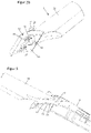
- Lamp 1 has a lamp housing 2 and a first fastening part 3 and a second fastening part 4.
- the lamp 1 is shown in its operating position.
- the first fastening part 3 and the second fastening part 4 are shown.
- the interaction of the first and second fastening parts 3, 4 is shown in the operating position.
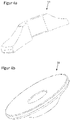
- the washer 51 is shown, which is part of the fastener 5 of the present embodiment.
- the second fastening part 4 is integrated in the lamp housing 2 in one piece.
- the first attachment part 3 is a separate element from the lamp housing 2 .
- the fastening means 5 are also separate elements in each case.
- the first fastening part 3 has a mounting section 31 and a first fastening section 32 .
- the first mounting section 31 is designed in the manner of a hollow cylinder and is suitable for attaching the lamp 1 to a lamp mast by placing the mounting section 31 on the spigot of the lamp mast.
- the first fastening section 32 has a first contact surface 35 which is curved about an imaginary axis of rotation not shown in the figures.
- the second fastening part 4 has a second contact surface 45 which is curved in a manner corresponding to the first contact surface 35 .
- Both contact surfaces 35, 45 are each formed as a circular arc section whose center coincides with the axis of rotation.
- the design of the first and second contact surfaces 35, 45 allows the two fastening parts 3, 4 to rotate relative to one another about the axis of rotation in such a way that the contact surfaces 35, 45 can be in different angular positions between the two fastening parts 3, 4 with respect to an angle about the axis of rotation can be adjusted, in each case abut each other over a large area.
- a first discretization device 33 is provided on the first contact surface 35 and is designed to correspond to a second discretization device 43 that is provided on the second contact surface 45 .
- these discretization devices 33, 43 makes it easier for a fitter to align the lamp 1 in a discrete, desired angular position relative to a component. In the exemplary embodiment shown, this is made possible by the fact that if the fastening means 52 designed as screws are loosely screwed into fastening anchors 44, the two fastening parts 3, 4 can still be twisted relative to one another, while the discretization devices 33, 43 can be felt by the fitter when the fastening parts are twisted 3, 4 specify angular positions relative to one another.
- the first fastening part 3 has two passages 34 in its first fastening section 32, each of which extends longitudinally in a direction perpendicular to the axis of rotation, with the passages 34 in the present case being designed as oblong holes.
- the bushings 34 are spaced apart from one another in the direction of the axis of rotation by a distance within the extent of which along the axis of rotation the mounting section 31 of the first fastening part 3 is arranged in the present case.
- the second fastening part 4 has two fastening anchors 44 in its second fastening section 45, which in the present case are designed as a blind hole, with a thread being provided in each of the blind holes.
- Each of the fastening anchors 44 is assigned to exactly one of the bushings 34 .
- the fastening means 5 are identical in the present case and are designed as a screw with a bolt 53 and a head part 52 and also include a washer 51. Washer 51 and head part 52 together form the fastening head of the fastening means 5.
- the washer 51 forms the fastening surface of the fastening means 5, with this fastening surface being, in particular, of figure 4 including the Figures 4a and 4b can be seen, is spherically curved and is thus formed in the manner of a spherical segment.
- the first attachment section 32 forms surface sections 320 , with each of the surface sections 320 enclosing exactly one of the passages 34 .
- the surface sections 320 each extend beyond the passage 34 both in the direction of the axis of rotation and in a direction perpendicular to the axis of rotation.
- the surface section 320 has a spherical curvature, which is designed to correspond to the spherical curvature of the fastening surface formed by the washer 51 . In the present case, therefore, the mutually facing sides of surface section 320 and the associated fastening surface are curved to correspond to one another, in this case spherically curved with the same radius of curvature.
- this radius of curvature corresponds to the length of an imaginary line that runs perpendicular to the axis of rotation and strikes surface section 320 perpendicularly and whose length is defined by axis of rotation and surface section 320 . It is obvious to the person skilled in the art that this enables a very simple and very reliable installation of the lamp 1 on a component in different angular positions of the two fastening parts 3, 4 relative to one another.
- the washer 51 in all of the Angular range adjustable relative angular position of the first and second fastening part 3, 4 to each other with the same surface on top of the surface section 320 and can therefore easily allow sufficient contact pressure on the first fastening section 32 in the direction of the second fastening section 42 thanks to the sufficiently large surface.
- the spherical configuration of surface section 320 and washer 51 it is possible to arrange washer 51 in different rotational positions relative to surface section 320 without changing the area with which washer 51 presses against surface section 320.
- a fitter can thus use the fastening means 5 to fasten the two fastening parts 3, 4 to one another in a particularly simple manner, without having to pay attention to a particular alignment of the fastening means 5.
Landscapes
- Engineering & Computer Science (AREA)
- General Engineering & Computer Science (AREA)
- Non-Portable Lighting Devices Or Systems Thereof (AREA)
- Fastening Of Light Sources Or Lamp Holders (AREA)
Applications Claiming Priority (1)
| Application Number | Priority Date | Filing Date | Title |
|---|---|---|---|
| DE102018131419.1A DE102018131419A1 (de) | 2018-12-07 | 2018-12-07 | Leuchte mit Befestigungsvorrichtung zur Mastmontage |
Publications (2)
| Publication Number | Publication Date |
|---|---|
| EP3663636A1 EP3663636A1 (de) | 2020-06-10 |
| EP3663636B1 true EP3663636B1 (de) | 2022-11-16 |
Family
ID=68732837
Family Applications (1)
| Application Number | Title | Priority Date | Filing Date |
|---|---|---|---|
| EP19212408.9A Active EP3663636B1 (de) | 2018-12-07 | 2019-11-29 | Leuchte mit befestigungsvorrichtung zur mastmontage |
Country Status (3)
| Country | Link |
|---|---|
| EP (1) | EP3663636B1 (pl) |
| DE (1) | DE102018131419A1 (pl) |
| PL (1) | PL3663636T3 (pl) |
Family Cites Families (11)
| Publication number | Priority date | Publication date | Assignee | Title |
|---|---|---|---|---|
| DE7538038U (de) * | 1976-03-25 | Hans Knuerr Kg Mechanik Fuer Die Elektronik, 8000 Muenchen | Profilträger-SchnellverschluB | |
| US1254068A (en) * | 1917-01-25 | 1918-01-22 | Henry E Procunier | Lamp holder and adjuster. |
| US5251118A (en) * | 1991-08-16 | 1993-10-05 | Devine Lighting, Inc. | Modular lighting system and method |
| DE19612182C1 (de) * | 1996-03-27 | 1997-08-21 | Langmatz Lic Gmbh | Vorrichtung zum Befestigen einer Signalkammer am Mast einer Signalanlage |
| DE102007054997B4 (de) * | 2007-11-17 | 2019-05-16 | Volkswagen Ag | Fahrzeugaußenspiegelanordnung, insbesondere Brüstungsspiegelanordnung |
| DE202009003239U1 (de) * | 2009-03-06 | 2009-07-02 | Autev Ag | Leuchte mit schwenkbaren Leuchtenflügeln |
| KR100966582B1 (ko) * | 2009-08-13 | 2010-06-29 | (주)파트라 | 등주용 등기구 |
| MY164271A (en) * | 2010-06-08 | 2017-11-30 | Dongguan Kingsun Optoelect Co | Led street lamp |
| KR101263724B1 (ko) * | 2011-06-08 | 2013-05-13 | 서울특별시시설관리공단 | 가로등 조사각 조절장치 |
| US10274177B2 (en) * | 2014-05-23 | 2019-04-30 | Hubbell Incorpoated | Luminaire with adjustable lamp modules |
| WO2016172924A1 (zh) * | 2015-04-30 | 2016-11-03 | 浙江晶日照明科技有限公司 | 一种灯体与灯杆的连接结构 |
-
2018
- 2018-12-07 DE DE102018131419.1A patent/DE102018131419A1/de not_active Withdrawn
-
2019
- 2019-11-29 EP EP19212408.9A patent/EP3663636B1/de active Active
- 2019-11-29 PL PL19212408.9T patent/PL3663636T3/pl unknown
Also Published As
| Publication number | Publication date |
|---|---|
| EP3663636A1 (de) | 2020-06-10 |
| DE102018131419A1 (de) | 2020-06-10 |
| PL3663636T3 (pl) | 2023-05-22 |
Similar Documents
| Publication | Publication Date | Title |
|---|---|---|
| EP0086937B1 (de) | Lösbare Verbindung von zwei rechtwinklig zueinander stehenden Platten, vorzugsweise Möbelplatten | |
| EP0064290B1 (de) | Vorrichtung zur Halterung von Verkleidungsplatten und dgl. an Bauwerksteilen | |
| DE3521783C1 (de) | Abstandsbüchse für die Befestigung eines Beschlagteils an einem mit einem vorgesetzten Profilteil versehenen Hohlprofil | |
| EP1222406B1 (de) | Halter für kopfschrauben | |
| EP3586012B1 (de) | Befestigungsvorrichtung und befestigungsbaugruppe | |
| EP3663636B1 (de) | Leuchte mit befestigungsvorrichtung zur mastmontage | |
| WO2009103535A1 (de) | Montagevorrichtung für deckeneinbau- bzw. deckenanbauleuchte | |
| EP0652401A2 (de) | Aussenleuchte mit einer Vorrichtung zur Mastbefestigung | |
| EP0882898A1 (de) | Verankerungseinheit | |
| DE29714671U1 (de) | Lochscheibe | |
| EP1085257A1 (de) | Beleuchtungsscheinwerfer mit Verdrehschutz | |
| DE3437089A1 (de) | Klemmvorrichtung | |
| DE202021003302U1 (de) | Befestigungssystem, insbesondere für den Markisenfuß einer Camping-Markisenausstellstange | |
| DE102004022279B4 (de) | Vorrichtung zur Befestigung von Dämmstoffelementen an ebenen Flächen | |
| EP0907032B1 (de) | Halteelement | |
| DE2416887B2 (de) | Befestigungsvorrichtung fuer eine deckeneinbauleuchte | |
| DE202014010156U1 (de) | Befestigungselement zur Befestigung von Anbauteilen an gedämmten Gebäudewänden | |
| DE202010001441U1 (de) | Justiersystem für Bauelemente | |
| DE202025104335U1 (de) | Vorrichtung zur Montage eines Fensterrahmens an einem Rolladenkasten | |
| WO2018167044A1 (de) | Batterieklemme | |
| DE2834375C2 (pl) | ||
| DE202023100950U1 (de) | Drehmechanismus und dessen Beleuchtungseinrichtung | |
| CH656178A5 (en) | Hinge for the adjustable fastening of a door wing or window wing having an overlap | |
| DE9311146U1 (de) | Einbaueinheit für eine Deckenleuchte | |
| DE3685961T2 (de) | Externe fixateuranordnung. |
Legal Events
| Date | Code | Title | Description |
|---|---|---|---|
| PUAI | Public reference made under article 153(3) epc to a published international application that has entered the european phase |
Free format text: ORIGINAL CODE: 0009012 |
|
| STAA | Information on the status of an ep patent application or granted ep patent |
Free format text: STATUS: THE APPLICATION HAS BEEN PUBLISHED |
|
| AK | Designated contracting states |
Kind code of ref document: A1 Designated state(s): AL AT BE BG CH CY CZ DE DK EE ES FI FR GB GR HR HU IE IS IT LI LT LU LV MC MK MT NL NO PL PT RO RS SE SI SK SM TR |
|
| AX | Request for extension of the european patent |
Extension state: BA ME |
|
| STAA | Information on the status of an ep patent application or granted ep patent |
Free format text: STATUS: REQUEST FOR EXAMINATION WAS MADE |
|
| 17P | Request for examination filed |
Effective date: 20201210 |
|
| RBV | Designated contracting states (corrected) |
Designated state(s): AL AT BE BG CH CY CZ DE DK EE ES FI FR GB GR HR HU IE IS IT LI LT LU LV MC MK MT NL NO PL PT RO RS SE SI SK SM TR |
|
| GRAP | Despatch of communication of intention to grant a patent |
Free format text: ORIGINAL CODE: EPIDOSNIGR1 |
|
| STAA | Information on the status of an ep patent application or granted ep patent |
Free format text: STATUS: GRANT OF PATENT IS INTENDED |
|
| INTG | Intention to grant announced |
Effective date: 20220603 |
|
| GRAS | Grant fee paid |
Free format text: ORIGINAL CODE: EPIDOSNIGR3 |
|
| GRAA | (expected) grant |
Free format text: ORIGINAL CODE: 0009210 |
|
| STAA | Information on the status of an ep patent application or granted ep patent |
Free format text: STATUS: THE PATENT HAS BEEN GRANTED |
|
| AK | Designated contracting states |
Kind code of ref document: B1 Designated state(s): AL AT BE BG CH CY CZ DE DK EE ES FI FR GB GR HR HU IE IS IT LI LT LU LV MC MK MT NL NO PL PT RO RS SE SI SK SM TR |
|
| REG | Reference to a national code |
Ref country code: GB Ref legal event code: FG4D Free format text: NOT ENGLISH |
|
| REG | Reference to a national code |
Ref country code: CH Ref legal event code: EP |
|
| REG | Reference to a national code |
Ref country code: DE Ref legal event code: R096 Ref document number: 502019006280 Country of ref document: DE |
|
| REG | Reference to a national code |
Ref country code: IE Ref legal event code: FG4D Free format text: LANGUAGE OF EP DOCUMENT: GERMAN |
|
| REG | Reference to a national code |
Ref country code: AT Ref legal event code: REF Ref document number: 1531965 Country of ref document: AT Kind code of ref document: T Effective date: 20221215 |
|
| REG | Reference to a national code |
Ref country code: LT Ref legal event code: MG9D |
|
| REG | Reference to a national code |
Ref country code: NL Ref legal event code: MP Effective date: 20221116 |
|
| PG25 | Lapsed in a contracting state [announced via postgrant information from national office to epo] |
Ref country code: SE Free format text: LAPSE BECAUSE OF FAILURE TO SUBMIT A TRANSLATION OF THE DESCRIPTION OR TO PAY THE FEE WITHIN THE PRESCRIBED TIME-LIMIT Effective date: 20221116 Ref country code: PT Free format text: LAPSE BECAUSE OF FAILURE TO SUBMIT A TRANSLATION OF THE DESCRIPTION OR TO PAY THE FEE WITHIN THE PRESCRIBED TIME-LIMIT Effective date: 20230316 Ref country code: NO Free format text: LAPSE BECAUSE OF FAILURE TO SUBMIT A TRANSLATION OF THE DESCRIPTION OR TO PAY THE FEE WITHIN THE PRESCRIBED TIME-LIMIT Effective date: 20230216 Ref country code: LT Free format text: LAPSE BECAUSE OF FAILURE TO SUBMIT A TRANSLATION OF THE DESCRIPTION OR TO PAY THE FEE WITHIN THE PRESCRIBED TIME-LIMIT Effective date: 20221116 Ref country code: FI Free format text: LAPSE BECAUSE OF FAILURE TO SUBMIT A TRANSLATION OF THE DESCRIPTION OR TO PAY THE FEE WITHIN THE PRESCRIBED TIME-LIMIT Effective date: 20221116 Ref country code: ES Free format text: LAPSE BECAUSE OF FAILURE TO SUBMIT A TRANSLATION OF THE DESCRIPTION OR TO PAY THE FEE WITHIN THE PRESCRIBED TIME-LIMIT Effective date: 20221116 |
|
| PG25 | Lapsed in a contracting state [announced via postgrant information from national office to epo] |
Ref country code: RS Free format text: LAPSE BECAUSE OF FAILURE TO SUBMIT A TRANSLATION OF THE DESCRIPTION OR TO PAY THE FEE WITHIN THE PRESCRIBED TIME-LIMIT Effective date: 20221116 Ref country code: LV Free format text: LAPSE BECAUSE OF FAILURE TO SUBMIT A TRANSLATION OF THE DESCRIPTION OR TO PAY THE FEE WITHIN THE PRESCRIBED TIME-LIMIT Effective date: 20221116 Ref country code: IS Free format text: LAPSE BECAUSE OF FAILURE TO SUBMIT A TRANSLATION OF THE DESCRIPTION OR TO PAY THE FEE WITHIN THE PRESCRIBED TIME-LIMIT Effective date: 20230316 Ref country code: HR Free format text: LAPSE BECAUSE OF FAILURE TO SUBMIT A TRANSLATION OF THE DESCRIPTION OR TO PAY THE FEE WITHIN THE PRESCRIBED TIME-LIMIT Effective date: 20221116 Ref country code: GR Free format text: LAPSE BECAUSE OF FAILURE TO SUBMIT A TRANSLATION OF THE DESCRIPTION OR TO PAY THE FEE WITHIN THE PRESCRIBED TIME-LIMIT Effective date: 20230217 |
|
| PG25 | Lapsed in a contracting state [announced via postgrant information from national office to epo] |
Ref country code: NL Free format text: LAPSE BECAUSE OF FAILURE TO SUBMIT A TRANSLATION OF THE DESCRIPTION OR TO PAY THE FEE WITHIN THE PRESCRIBED TIME-LIMIT Effective date: 20221116 |
|
| P01 | Opt-out of the competence of the unified patent court (upc) registered |
Effective date: 20230527 |
|
| PG25 | Lapsed in a contracting state [announced via postgrant information from national office to epo] |
Ref country code: SM Free format text: LAPSE BECAUSE OF FAILURE TO SUBMIT A TRANSLATION OF THE DESCRIPTION OR TO PAY THE FEE WITHIN THE PRESCRIBED TIME-LIMIT Effective date: 20221116 Ref country code: RO Free format text: LAPSE BECAUSE OF FAILURE TO SUBMIT A TRANSLATION OF THE DESCRIPTION OR TO PAY THE FEE WITHIN THE PRESCRIBED TIME-LIMIT Effective date: 20221116 Ref country code: EE Free format text: LAPSE BECAUSE OF FAILURE TO SUBMIT A TRANSLATION OF THE DESCRIPTION OR TO PAY THE FEE WITHIN THE PRESCRIBED TIME-LIMIT Effective date: 20221116 Ref country code: DK Free format text: LAPSE BECAUSE OF FAILURE TO SUBMIT A TRANSLATION OF THE DESCRIPTION OR TO PAY THE FEE WITHIN THE PRESCRIBED TIME-LIMIT Effective date: 20221116 Ref country code: CZ Free format text: LAPSE BECAUSE OF FAILURE TO SUBMIT A TRANSLATION OF THE DESCRIPTION OR TO PAY THE FEE WITHIN THE PRESCRIBED TIME-LIMIT Effective date: 20221116 |
|
| REG | Reference to a national code |
Ref country code: DE Ref legal event code: R097 Ref document number: 502019006280 Country of ref document: DE |
|
| PG25 | Lapsed in a contracting state [announced via postgrant information from national office to epo] |
Ref country code: SK Free format text: LAPSE BECAUSE OF FAILURE TO SUBMIT A TRANSLATION OF THE DESCRIPTION OR TO PAY THE FEE WITHIN THE PRESCRIBED TIME-LIMIT Effective date: 20221116 Ref country code: LU Free format text: LAPSE BECAUSE OF NON-PAYMENT OF DUE FEES Effective date: 20221129 Ref country code: AL Free format text: LAPSE BECAUSE OF FAILURE TO SUBMIT A TRANSLATION OF THE DESCRIPTION OR TO PAY THE FEE WITHIN THE PRESCRIBED TIME-LIMIT Effective date: 20221116 |
|
| PLBE | No opposition filed within time limit |
Free format text: ORIGINAL CODE: 0009261 |
|
| STAA | Information on the status of an ep patent application or granted ep patent |
Free format text: STATUS: NO OPPOSITION FILED WITHIN TIME LIMIT |
|
| 26N | No opposition filed |
Effective date: 20230817 |
|
| PG25 | Lapsed in a contracting state [announced via postgrant information from national office to epo] |
Ref country code: IE Free format text: LAPSE BECAUSE OF NON-PAYMENT OF DUE FEES Effective date: 20221129 |
|
| PG25 | Lapsed in a contracting state [announced via postgrant information from national office to epo] |
Ref country code: SI Free format text: LAPSE BECAUSE OF FAILURE TO SUBMIT A TRANSLATION OF THE DESCRIPTION OR TO PAY THE FEE WITHIN THE PRESCRIBED TIME-LIMIT Effective date: 20221116 |
|
| PG25 | Lapsed in a contracting state [announced via postgrant information from national office to epo] |
Ref country code: HU Free format text: LAPSE BECAUSE OF FAILURE TO SUBMIT A TRANSLATION OF THE DESCRIPTION OR TO PAY THE FEE WITHIN THE PRESCRIBED TIME-LIMIT; INVALID AB INITIO Effective date: 20191129 |
|
| PG25 | Lapsed in a contracting state [announced via postgrant information from national office to epo] |
Ref country code: CY Free format text: LAPSE BECAUSE OF FAILURE TO SUBMIT A TRANSLATION OF THE DESCRIPTION OR TO PAY THE FEE WITHIN THE PRESCRIBED TIME-LIMIT Effective date: 20221116 |
|
| PG25 | Lapsed in a contracting state [announced via postgrant information from national office to epo] |
Ref country code: MK Free format text: LAPSE BECAUSE OF FAILURE TO SUBMIT A TRANSLATION OF THE DESCRIPTION OR TO PAY THE FEE WITHIN THE PRESCRIBED TIME-LIMIT Effective date: 20221116 Ref country code: IT Free format text: LAPSE BECAUSE OF FAILURE TO SUBMIT A TRANSLATION OF THE DESCRIPTION OR TO PAY THE FEE WITHIN THE PRESCRIBED TIME-LIMIT Effective date: 20221116 |
|
| PG25 | Lapsed in a contracting state [announced via postgrant information from national office to epo] |
Ref country code: MC Free format text: LAPSE BECAUSE OF FAILURE TO SUBMIT A TRANSLATION OF THE DESCRIPTION OR TO PAY THE FEE WITHIN THE PRESCRIBED TIME-LIMIT Effective date: 20221116 |
|
| PG25 | Lapsed in a contracting state [announced via postgrant information from national office to epo] |
Ref country code: MC Free format text: LAPSE BECAUSE OF FAILURE TO SUBMIT A TRANSLATION OF THE DESCRIPTION OR TO PAY THE FEE WITHIN THE PRESCRIBED TIME-LIMIT Effective date: 20221116 |
|
| PG25 | Lapsed in a contracting state [announced via postgrant information from national office to epo] |
Ref country code: BG Free format text: LAPSE BECAUSE OF FAILURE TO SUBMIT A TRANSLATION OF THE DESCRIPTION OR TO PAY THE FEE WITHIN THE PRESCRIBED TIME-LIMIT Effective date: 20221116 |
|
| PG25 | Lapsed in a contracting state [announced via postgrant information from national office to epo] |
Ref country code: MT Free format text: LAPSE BECAUSE OF FAILURE TO SUBMIT A TRANSLATION OF THE DESCRIPTION OR TO PAY THE FEE WITHIN THE PRESCRIBED TIME-LIMIT Effective date: 20221116 |
|
| PGFP | Annual fee paid to national office [announced via postgrant information from national office to epo] |
Ref country code: DE Payment date: 20250122 Year of fee payment: 6 |
|
| REG | Reference to a national code |
Ref country code: CH Ref legal event code: U11 Free format text: ST27 STATUS EVENT CODE: U-0-0-U10-U11 (AS PROVIDED BY THE NATIONAL OFFICE) Effective date: 20251201 |
|
| PG25 | Lapsed in a contracting state [announced via postgrant information from national office to epo] |
Ref country code: TR Free format text: LAPSE BECAUSE OF FAILURE TO SUBMIT A TRANSLATION OF THE DESCRIPTION OR TO PAY THE FEE WITHIN THE PRESCRIBED TIME-LIMIT Effective date: 20221116 |
|
| PGFP | Annual fee paid to national office [announced via postgrant information from national office to epo] |
Ref country code: GB Payment date: 20251120 Year of fee payment: 7 |
|
| PGFP | Annual fee paid to national office [announced via postgrant information from national office to epo] |
Ref country code: AT Payment date: 20251117 Year of fee payment: 7 |
|
| PGFP | Annual fee paid to national office [announced via postgrant information from national office to epo] |
Ref country code: FR Payment date: 20251125 Year of fee payment: 7 |
|
| PGFP | Annual fee paid to national office [announced via postgrant information from national office to epo] |
Ref country code: BE Payment date: 20251118 Year of fee payment: 7 |
|
| PGFP | Annual fee paid to national office [announced via postgrant information from national office to epo] |
Ref country code: CH Payment date: 20251201 Year of fee payment: 7 |
|
| PGFP | Annual fee paid to national office [announced via postgrant information from national office to epo] |
Ref country code: PL Payment date: 20251119 Year of fee payment: 7 |