EP3663598B1 - Lager- und lenkmechanismus - Google Patents
Lager- und lenkmechanismus Download PDFInfo
- Publication number
- EP3663598B1 EP3663598B1 EP18840701.9A EP18840701A EP3663598B1 EP 3663598 B1 EP3663598 B1 EP 3663598B1 EP 18840701 A EP18840701 A EP 18840701A EP 3663598 B1 EP3663598 B1 EP 3663598B1
- Authority
- EP
- European Patent Office
- Prior art keywords
- radius
- bearing
- bush
- elastic ring
- rack
- Prior art date
- Legal status (The legal status is an assumption and is not a legal conclusion. Google has not performed a legal analysis and makes no representation as to the accuracy of the status listed.)
- Active
Links
Images


Classifications
-
- B—PERFORMING OPERATIONS; TRANSPORTING
- B62—LAND VEHICLES FOR TRAVELLING OTHERWISE THAN ON RAILS
- B62D—MOTOR VEHICLES; TRAILERS
- B62D3/00—Steering gears
- B62D3/02—Steering gears mechanical
- B62D3/12—Steering gears mechanical of rack-and-pinion type
- B62D3/126—Steering gears mechanical of rack-and-pinion type characterised by the rack
-
- F—MECHANICAL ENGINEERING; LIGHTING; HEATING; WEAPONS; BLASTING
- F16—ENGINEERING ELEMENTS AND UNITS; GENERAL MEASURES FOR PRODUCING AND MAINTAINING EFFECTIVE FUNCTIONING OF MACHINES OR INSTALLATIONS; THERMAL INSULATION IN GENERAL
- F16C—SHAFTS; FLEXIBLE SHAFTS; ELEMENTS OR CRANKSHAFT MECHANISMS; ROTARY BODIES OTHER THAN GEARING ELEMENTS; BEARINGS
- F16C17/00—Sliding-contact bearings for exclusively rotary movement
- F16C17/02—Sliding-contact bearings for exclusively rotary movement for radial load only
-
- F—MECHANICAL ENGINEERING; LIGHTING; HEATING; WEAPONS; BLASTING
- F16—ENGINEERING ELEMENTS AND UNITS; GENERAL MEASURES FOR PRODUCING AND MAINTAINING EFFECTIVE FUNCTIONING OF MACHINES OR INSTALLATIONS; THERMAL INSULATION IN GENERAL
- F16C—SHAFTS; FLEXIBLE SHAFTS; ELEMENTS OR CRANKSHAFT MECHANISMS; ROTARY BODIES OTHER THAN GEARING ELEMENTS; BEARINGS
- F16C25/00—Bearings for exclusively rotary movement adjustable for wear or play
- F16C25/02—Sliding-contact bearings
- F16C25/04—Sliding-contact bearings self-adjusting
-
- F—MECHANICAL ENGINEERING; LIGHTING; HEATING; WEAPONS; BLASTING
- F16—ENGINEERING ELEMENTS AND UNITS; GENERAL MEASURES FOR PRODUCING AND MAINTAINING EFFECTIVE FUNCTIONING OF MACHINES OR INSTALLATIONS; THERMAL INSULATION IN GENERAL
- F16C—SHAFTS; FLEXIBLE SHAFTS; ELEMENTS OR CRANKSHAFT MECHANISMS; ROTARY BODIES OTHER THAN GEARING ELEMENTS; BEARINGS
- F16C27/00—Elastic or yielding bearings or bearing supports, for exclusively rotary movement
- F16C27/06—Elastic or yielding bearings or bearing supports, for exclusively rotary movement by means of parts of rubber or like materials
- F16C27/063—Sliding contact bearings
-
- F—MECHANICAL ENGINEERING; LIGHTING; HEATING; WEAPONS; BLASTING
- F16—ENGINEERING ELEMENTS AND UNITS; GENERAL MEASURES FOR PRODUCING AND MAINTAINING EFFECTIVE FUNCTIONING OF MACHINES OR INSTALLATIONS; THERMAL INSULATION IN GENERAL
- F16C—SHAFTS; FLEXIBLE SHAFTS; ELEMENTS OR CRANKSHAFT MECHANISMS; ROTARY BODIES OTHER THAN GEARING ELEMENTS; BEARINGS
- F16C29/00—Bearings for parts moving only linearly
- F16C29/002—Elastic or yielding linear bearings or bearing supports
-
- F—MECHANICAL ENGINEERING; LIGHTING; HEATING; WEAPONS; BLASTING
- F16—ENGINEERING ELEMENTS AND UNITS; GENERAL MEASURES FOR PRODUCING AND MAINTAINING EFFECTIVE FUNCTIONING OF MACHINES OR INSTALLATIONS; THERMAL INSULATION IN GENERAL
- F16C—SHAFTS; FLEXIBLE SHAFTS; ELEMENTS OR CRANKSHAFT MECHANISMS; ROTARY BODIES OTHER THAN GEARING ELEMENTS; BEARINGS
- F16C29/00—Bearings for parts moving only linearly
- F16C29/02—Sliding-contact bearings
-
- B—PERFORMING OPERATIONS; TRANSPORTING
- B62—LAND VEHICLES FOR TRAVELLING OTHERWISE THAN ON RAILS
- B62D—MOTOR VEHICLES; TRAILERS
- B62D3/00—Steering gears
- B62D3/02—Steering gears mechanical
- B62D3/12—Steering gears mechanical of rack-and-pinion type
-
- F—MECHANICAL ENGINEERING; LIGHTING; HEATING; WEAPONS; BLASTING
- F16—ENGINEERING ELEMENTS AND UNITS; GENERAL MEASURES FOR PRODUCING AND MAINTAINING EFFECTIVE FUNCTIONING OF MACHINES OR INSTALLATIONS; THERMAL INSULATION IN GENERAL
- F16C—SHAFTS; FLEXIBLE SHAFTS; ELEMENTS OR CRANKSHAFT MECHANISMS; ROTARY BODIES OTHER THAN GEARING ELEMENTS; BEARINGS
- F16C2326/00—Articles relating to transporting
- F16C2326/20—Land vehicles
- F16C2326/24—Steering systems, e.g. steering rods or columns
-
- F—MECHANICAL ENGINEERING; LIGHTING; HEATING; WEAPONS; BLASTING
- F16—ENGINEERING ELEMENTS AND UNITS; GENERAL MEASURES FOR PRODUCING AND MAINTAINING EFFECTIVE FUNCTIONING OF MACHINES OR INSTALLATIONS; THERMAL INSULATION IN GENERAL
- F16C—SHAFTS; FLEXIBLE SHAFTS; ELEMENTS OR CRANKSHAFT MECHANISMS; ROTARY BODIES OTHER THAN GEARING ELEMENTS; BEARINGS
- F16C2361/00—Apparatus or articles in engineering in general
- F16C2361/61—Toothed gear systems, e.g. support of pinion shafts
-
- F—MECHANICAL ENGINEERING; LIGHTING; HEATING; WEAPONS; BLASTING
- F16—ENGINEERING ELEMENTS AND UNITS; GENERAL MEASURES FOR PRODUCING AND MAINTAINING EFFECTIVE FUNCTIONING OF MACHINES OR INSTALLATIONS; THERMAL INSULATION IN GENERAL
- F16C—SHAFTS; FLEXIBLE SHAFTS; ELEMENTS OR CRANKSHAFT MECHANISMS; ROTARY BODIES OTHER THAN GEARING ELEMENTS; BEARINGS
- F16C35/00—Rigid support of bearing units; Housings, e.g. caps, covers
- F16C35/02—Rigid support of bearing units; Housings, e.g. caps, covers in the case of sliding-contact bearings
-
- F—MECHANICAL ENGINEERING; LIGHTING; HEATING; WEAPONS; BLASTING
- F16—ENGINEERING ELEMENTS AND UNITS; GENERAL MEASURES FOR PRODUCING AND MAINTAINING EFFECTIVE FUNCTIONING OF MACHINES OR INSTALLATIONS; THERMAL INSULATION IN GENERAL
- F16C—SHAFTS; FLEXIBLE SHAFTS; ELEMENTS OR CRANKSHAFT MECHANISMS; ROTARY BODIES OTHER THAN GEARING ELEMENTS; BEARINGS
- F16C43/00—Assembling bearings
- F16C43/02—Assembling sliding-contact bearings
-
- F—MECHANICAL ENGINEERING; LIGHTING; HEATING; WEAPONS; BLASTING
- F16—ENGINEERING ELEMENTS AND UNITS; GENERAL MEASURES FOR PRODUCING AND MAINTAINING EFFECTIVE FUNCTIONING OF MACHINES OR INSTALLATIONS; THERMAL INSULATION IN GENERAL
- F16H—GEARING
- F16H55/00—Elements with teeth or friction surfaces for conveying motion; Worms, pulleys or sheaves for gearing mechanisms
- F16H55/02—Toothed members; Worms
- F16H55/26—Racks
- F16H55/28—Special devices for taking up backlash
- F16H2055/281—Cylindrical or half-cylindrical bushings around the rack, e.g. using special wedges to reduce play
Definitions
- the present invention relates to a bearing, and in particular to a bearing suitable for a rack bush used in a rack-and-pinion steering mechanism.
- the Patent Literature 1 describes a rack bush used in a rack-and-pinion steering mechanism.
- This rack bush is housed in a circular cylindrical housing in a state that movement in the axial direction is restricted, and supports the load applied to a rack bar while allowing movement of the rack bar in the axial direction.
- the rack bush comprises: a circular cylindrical bearing body, which can be freely expanded and contracted in the radial direction, and into which the rack bar is inserted; and elastic rings, which are mounted on the bearing body and bias the bearing body inward in the radial direction.
- the bearing body is made of synthetic resin, and mounting grooves for mounting the elastic rings are formed in the outer peripheral surface of the bearing body, each in the circumferential direction.
- the bearing body is contracted in diameter by the elastic rings so that the rack bar inserted in the bearing body is tightened.
- the clearance between the inner peripheral surface of the bearing body and the outer peripheral surface of the rack bar is made to be zero, and thus it is possible to prevent generation of unpleasant sound owing to collision between the inner peripheral surface of the bearing body and the outer peripheral surface of the rack bar. Further, it is possible to prevent variation in the friction torque caused by a dimension error of the outer diameter of the rack bar.
- US 2015/204381 shows a rack and pinion steering mechanism comprising a bearing according to the preamble of claim 1.
- Patent Literature 1 Japanese Unexamined Patent Application Laid-Open No. 2008-151289
- the rack bush described in the Patent Literature 1 is housed in the housing with the elastic rings mounted on the bearing body being abutted against the inner peripheral surface of the housing, the elastic rings are compressively deformed and moved within the housing owing to the reaction force from the tires inputted into the rack bar. Accordingly, the time lag from the steering operation to actual change of the directions of the tires becomes larger, and this affects feeling of steering operation unfavorably.
- the present invention has been made taking the above conditions into consideration, and an object of the invention is to provide a bearing suitable for a rack bush that can reduce a bad effect on the feeling of steering operation.
- a mounting groove for mounting an elastic ring is formed in the circumferential direction in the outer peripheral surface of a bush body through which a rack bar is inserted, so as to be provided with a large-diameter part where the groove bottom in the circumferential direction has a first radius and a small-diameter part where the groove bottom in the circumferential direction has a second radius smaller than the first radius.
- a sum of the first radius and the wire diameter of the elastic body forming the elastic ring is larger than the radius of the outer peripheral surface of the bush body while a sum of the second radius and the wire diameter of the elastic body forming the elastic ring is smaller than or equal to the radius of the outer peripheral surface of the bush body.
- the present invention provides a bearing, comprising:
- a rack-and-pinion steering mechanism comprising:
- the mounting groove for mounting the elastic ring has the large-diameter part where the groove bottom in the circumferential direction has a first radius and a small diameter part where the groove bottom in the circumferential direction has a second radius smaller than the first radius.
- an elastic ring protruding part where the elastic ring protrudes largely from the outer peripheral surface of the bush body and an elastic ring embedded part where the elastic ring is embedded in or protrudes small from the outer peripheral part of the bush body.
- the present invention can provide a rack bush that can reduce the effect on the feeling of steering operation.
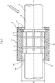
- Fig. 1 is a partial cross-section view of a part of a rack-and-pinion steering mechanism according to the present embodiment.
- the rack-and-pinion steering mechanism of the present embodiment comprises: a rack bush 1, which supports a load applied to a rack bar 5 while allowing movement of the rack bar 5 in the direction of the axis O; and a cylindrical housing 4, which houses the rack bush 1 while restricting movement of the rack bush 1 in the direction of the axis O.
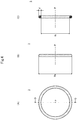
- Figs. 2(A) and 2(B) are respectively a front view and a side view of the rack bush 1
- Fig. 2(C) is an A-A cross-section view of the rack bush 1 shown in Fig. 2(B) .
- the rack bush 1 comprises: a bush body 2 through which the rack bar 5 is inserted; and elastic rings 3 mounted on the bush body 2.
- the present embodiment shows an example in which two elastic rings 3 are mounted on the bush body 2, it is possible that one, three, or more elastic rings 3 are mounted on the bush body 2.
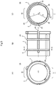
- Figs. 3(A), 3(B), and 3(C) are respectively a front view, a side view, and a back view of the bush body 2
- Fig. 3(D) is a B-B cross-section view of the bush body 2 shown in Fig. 3(A)
- Fig. 3(E) is a C-C cross-section view of the bush body 2 shown in Fig. 3(B) .
- the bush body 2 is formed of synthetic resin having good sliding characteristics such as polyacetal resin, polyamide resin, or polyethylene resin, and is a cylindrical member which can be freely expanded and contracted in the radial direction.
- the bush body 2 comprises: a sliding surface 21, which is formed in an inner peripheral surface 20 and comes in sliding contact with an outer peripheral surface 50 of the rack bar 5 inserted; a plurality of first slits 25 and second slits 26, which are arranged alternately in the circumferential direction at regular intervals; an engagement protrusion 27, which is formed on an outer peripheral surface 22; and mounting grooves 28, which are formed in the outer peripheral surface 22 in the circumferential direction in order to mount the elastic rings 3.
- the first slits 25 are each formed along the direction of the axis O from one end surface 23 toward the other end surface 24, and the second slits 26 are each formed along the direction of the axis O from the other end surface 24 toward the one end surface 23.
- the bush body 2 can be deformed in the diameter contracting direction owing to the plurality of first slits 25 and second slits 26 arranged alternately in the circumferential direction at regular intervals.
- the engagement protrusion 27 protrudes outward in the radial direction from the outer peripheral surface 22 on the side of the one end surface 23, and is received in an engagement recess (not shown) which is formed to cut off the inner peripheral surface 40 at one end surface 41 of the housing 4.
- the rack bush 1 housed in the housing 4 is restricted in rotation around the axis O.
- a ring-shaped lid 6 is attached to the one end surface 41 of the housing 4 in a state that the engagement protrusion 27 is received in the engagement recess of the housing 4.
- the rack bush 1 housed in the housing 4 is restricted in movement in the direction of the axis O (See Fig. 1 ).
- Each of the mounting grooves 28 is formed in the outer peripheral surface 22 along the circumferential direction, and has a large-diameter part 280 where the groove bottom 29 in the circumferential direction has a first radius r1 and a small-diameter part 281 where the groove bottom 29 in the circumferential direction has a second radius r2 smaller than the first radius r1.
- the radius of the outer peripheral surface 22 as r0 and the wire diameter of the elastic body forming the elastic ring 3 as d (See Fig. 4 )
- the first radius r1 is set so that r1 + d > r0.
- Figs. 4(A) and 4(B) are respectively a front view and a side view of each elastic ring 3, and Fig. 4(C) is a D-D cross-section view of the elastic ring 3 shown in Fig. 4(A) .
- Each elastic ring 3 is an annular member formed of an elastic body such as synthetic resin, thermoplastic elastomer, or the like, and the inner circumference nRi on the side of the inner diameter Ri is shorter than the circumference of the groove bottom 29 of the mounting groove 28 of the bush body 2. Further, the outer diameter Re is larger than the inner diameter Rj of the housing 4 (See Fig. 1 ).
- the circumference nRi of the elastic ring 3 on the side of the inner diameter Ri is shorter than the circumference of the groove bottom 29 of the mounting groove 28 of the bush body 2.
- the elastic ring 3 biases the bush body 2 in the direction of contracting the diameter of the bush body 2 and tightens the rack bar 5 inserted in the bush body 2.
- the outer diameter Re of the elastic ring 3 is larger than the inner diameter Rj of the housing 4. Therefore, when the rack bush 1 is housed in the housing 4, the elastic ring 3 comes in pressed contact with the inner peripheral surface 40 of the housing 4, and accordingly is compressively deformed. As a result, the rack bush 1 is fitted in the housing 4.
- a reaction force supporting surface 42 is the inner peripheral surface 40 of the housing 4 opposed to the input direction of the reaction force N inputted to the rack bar 5 from a tire (not shown) via a tie rod (not shown) linked to the rack bar 5, and is an area including the site that generates the greatest reaction force to the reaction force N inputted to the rack bar 5 in the inner peripheral surface 40 of the housing 4.
- the rack bush 1 of the above configuration is positioned by the engagement between the engagement protrusion 27 of the bush body 2 and the engagement recess (not shown) of the housing 4 so that the small-diameter parts 281 of the mounting grooves 28 of the bush body 2 are positioned on the side of the reaction force supporting surface 42, or in other words, the elastic ring embedded parts 11 are positioned on the side of the reaction force supporting surface 42.
- each of the mounting grooves 28 of the bush body 2 has the large-diameter part 280 where the groove bottom in the circumferential direction has the first radius r1 and the small-diameter part 281 where the groove bottom in the circumferential direction has the second radius r2 smaller than the first radius r1.
- the rack bush 1 has the elastic protruding parts 10, in each of which the elastic ring 3 protrudes largely from the outer peripheral surface 22 of the bush body 2, and the elastic ring embedded parts 11, in each of which the elastic ring 3 is embedded in the outer peripheral surface 22 of the bush body 2.
- the rack bush 1 is housed in the housing 4, being positioned so that the elastic ring embedded parts 11 are positioned on the side of the reaction force supporting surface 42.
- the outer peripheral surface 22 of the bush body 2 is abutted against the inner peripheral surface 40 of the housing 4 without intervention of the elastic rings 3, and there is no gap between the outer peripheral surface 22 of the bush body 2 and the inner peripheral surface 40 of the housing 4.
- This improves the rigidity on the side of the reaction force supporting surface 42 and can suppress movement of the rack bar 5 within the housing 4 owing to the reaction force N of a tire. Thereby, the time lag from steering operation to actual change of the tire direction is reduced.
- the present embodiment can provide the rack bush 1 that reduces the effect on the feeling of steering operation.
- the present invention is not limited to the above embodiment, and can be varied variously.
- the present invention is not limited to this.
- the second radius r2 of the groove bottom 29 in the circumferential direction at the small-diameter part 281 of the mounting groove 28 is set so that the elastic ring 3 is embedded in the outer peripheral surface 22 of the bush body 2 at the elastic ring embedded part 11 or the amount of protrusion of the elastic ring 3 from the outer peripheral surface 22 of the bush body 2 is smaller than that at the elastic ring protruding part 10.
- the gap between the outer peripheral surface 22 of the bush body 2 and the inner peripheral surface 40 of the housing 4 is made smaller on the side of the reaction force supporting surface 42 of the housing 4, and movement of the rack bar 5 inside the housing 4 owing to the tire' s reaction force N is suppressed. Accordingly, the time lag from steering operation to actual change of the tire direction is reduced.
- the first slits 25 and the second slits 26 can be omitted from the bush body 2 on the side of the elastic ring protruding parts 10 (the large-diameter parts 280 of the mounting grooves 28).
- the first slits 25 and the second slits 26 can be arranged only on the side of the elastic ring embedded parts 11 (the small-diameter parts 281 of the mounting grooves 28).
- a plurality of first slits 25 are formed in the bush body 2 along the direction of the axis O from the one end surface 23 toward the other end surface 24, and a plurality of second slits 26 are formed along the direction of the axis O from the other end surface 24 toward the one end surface 23.
- the present invention is not limited to this. It is good enough if the bush body 2 can be freely expanded and contracted in radial direction.
- the bush body 2 may have only the first slits 25 or only the second slits 26.
- the bush body 2 has the cylindrical shape. However, it is good enough if the bush body 2 has a tubular shape adapted to the shape of the rack bar 5 to be inserted.
- 1, 1A rack bush; 2: bush body; 3: elastic ring; 4: housing; 5: rack bar; 6: lid; 10: elastic ring protruding part; 11: elastic ring embedded part; 20: inner peripheral surface of the bush body 2; 21: sliding surface of the bush body 2; 22: outer peripheral surface of the bush body 2; 23, 24: end surface of the bush body 2; 25: first slit; 26: second slit; 27: engagement part; 28: mounting groove; 29: groove bottom of the mounting groove 28; 40: inner peripheral surface of the housing 4; 41: end surface of the housing 4; 42: reaction force supporting surface of the housing 4; 43: reaction force supporting surface opposed surface of the housing 4; 280: large-diameter part of the mounting groove 28; and 281: small-diameter part of the mounting groove.
Landscapes
- Engineering & Computer Science (AREA)
- General Engineering & Computer Science (AREA)
- Mechanical Engineering (AREA)
- Chemical & Material Sciences (AREA)
- Combustion & Propulsion (AREA)
- Transportation (AREA)
- Support Of The Bearing (AREA)
- Sliding-Contact Bearings (AREA)
- Bearings For Parts Moving Linearly (AREA)
Claims (6)
- Lager (1), umfassend:einen Buchsenkörper (2), der sich in radialer Richtung frei ausdehnen und zusammenziehen kann; undeinen elastischen Ring (3), der auf dem Buchsenkörper (2) angebracht ist;wobei der Buchsenkörper (2) eine Montagenut (28) aufweist, die in einer äußeren Umfangsfläche (22) in einer Umfangsrichtung zum Anbringen des elastischen Rings (3) ausgebildet ist;dadurch gekennzeichnet, dass die Montagenut (28) aufweist:ein Teil (280) mit großem Durchmesser, bei dem ein Radius eines Nutbodens (29) der Montagenut (28) ein erster Radius (r1) ist; undein Teil (281) mit kleinem Durchmesser, bei dem der Radius des Nutbodens (29) ein zweiter Radius (r2) ist, der kleiner ist als der erste Radius (r1).
- Lager (1) nach Anspruch 1, wobei das Ausmaß des Vorsprungs des elastischen Rings (3) aus dem Teil mit großem Durchmesser (280) größer ist als das Ausmaß des Vorsprungs aus dem Teil mit kleinem Durchmesser (281).
- Lager (1) nach Anspruch 1, wobeieine Summe aus dem ersten Radius (r1) und einem Drahtdurchmesser (d) eines den elastischen Ring (3) bildenden elastischen Körpers größer ist als ein Radius (r0) der äußeren Umfangsfläche (22) des Buchsenkörpers (2); undeine Summe aus dem zweiten Radius (r2) und dem Drahtdurchmesser (d) des den elastischen Ring (3) bildenden elastischen Körpers kleiner oder gleich dem Radius (r0) der äußeren Umfangsfläche (22) des Buchsenkörpers (2) ist.
- Lager (1) nach einem der Ansprüche 1 bis 3, wobei der Buchsenkörper (2) Schlitze (26) aufweist, die jeweils von einer Endfläche (26) zur anderen Endfläche (24) hin ausgebildet sind.
- Lager (1) nach Anspruch 4, wobei die Schlitze (26) in einer Umfangsrichtung des Buchsenkörpers (2) auf der Seite des Teils (281) mit kleinem Durchmesser der Montagenut (28) angeordnet sind.
- Zahnstangenlenkmechanismus, umfassend:ein Lager (1) nach einem der Ansprüche 1 bis 5, das eine auf eine Zahnstange (5) ausgeübte Last abstützt und dabei eine Bewegung der Zahnstange (5) in einer axialen Richtung (O) zulässt; undein zylindrisches Gehäuse (4), in dem das Lager (1) untergebracht ist und das die Bewegung des Lagers (1) in der axialen Richtung (O) begrenzt;wobei das Lager (1) in dem Gehäuse (4) so untergebracht ist, dass der Teil (281) mit kleinem Durchmesser der Montagenut (28) einer Reaktionskraftstützfläche (42) zugewandt ist, die eine innere Umfangsfläche (40) des Gehäuses (4) ist, die einer Eingangsrichtung einer Reaktionskraft (N) entgegengesetzt ist, die von einem Reifen über eine mit der Zahnstange (5) verbundene Spurstange in die Zahnstange (5) eingegeben wird.
Applications Claiming Priority (2)
| Application Number | Priority Date | Filing Date | Title |
|---|---|---|---|
| JP2017151134A JP6783719B2 (ja) | 2017-08-03 | 2017-08-03 | 軸受およびステアリング機構 |
| PCT/JP2018/028735 WO2019026928A1 (ja) | 2017-08-03 | 2018-07-31 | 軸受およびステアリング機構 |
Publications (3)
| Publication Number | Publication Date |
|---|---|
| EP3663598A1 EP3663598A1 (de) | 2020-06-10 |
| EP3663598A4 EP3663598A4 (de) | 2021-05-05 |
| EP3663598B1 true EP3663598B1 (de) | 2021-11-17 |
Family
ID=65232795
Family Applications (1)
| Application Number | Title | Priority Date | Filing Date |
|---|---|---|---|
| EP18840701.9A Active EP3663598B1 (de) | 2017-08-03 | 2018-07-31 | Lager- und lenkmechanismus |
Country Status (5)
| Country | Link |
|---|---|
| US (1) | US11548546B2 (de) |
| EP (1) | EP3663598B1 (de) |
| JP (1) | JP6783719B2 (de) |
| CN (1) | CN110998110B (de) |
| WO (1) | WO2019026928A1 (de) |
Families Citing this family (7)
| Publication number | Priority date | Publication date | Assignee | Title |
|---|---|---|---|---|
| JP6934801B2 (ja) * | 2017-10-20 | 2021-09-15 | マツダ株式会社 | ラックブッシュおよびステアリング機構 |
| US10837677B2 (en) * | 2018-09-05 | 2020-11-17 | Ojjo, Inc. | Multi-piece truss legs and related couplers |
| JP7324607B2 (ja) * | 2019-04-15 | 2023-08-10 | マツダ株式会社 | ステアリング装置 |
| JP7344027B2 (ja) * | 2019-07-12 | 2023-09-13 | Kyb株式会社 | ステアリング装置 |
| US11313508B2 (en) * | 2019-09-04 | 2022-04-26 | Raytheon Company | Radial positioning device |
| US11293488B1 (en) | 2021-07-02 | 2022-04-05 | Alfredo A. Ciotola | Compressively resilient bushing |
| CN114537508A (zh) * | 2022-02-28 | 2022-05-27 | 重庆长安汽车股份有限公司 | 汽车机械转向器总成 |
Family Cites Families (21)
| Publication number | Priority date | Publication date | Assignee | Title |
|---|---|---|---|---|
| JP2005178482A (ja) | 2003-12-17 | 2005-07-07 | Koyo Seiko Co Ltd | ステアリング装置 |
| JP4935080B2 (ja) * | 2006-01-16 | 2012-05-23 | 株式会社ジェイテクト | ブッシュ軸受及びそれを用いた自動車のラック−ピニオン式操舵装置 |
| US7665747B2 (en) * | 2006-10-13 | 2010-02-23 | Gm Global Technology Operations, Inc. | Steering gear assembly having rack bushing |
| JP4940931B2 (ja) | 2006-12-19 | 2012-05-30 | オイレス工業株式会社 | 滑り軸受 |
| JP5167754B2 (ja) * | 2007-10-18 | 2013-03-21 | オイレス工業株式会社 | ブッシュ軸受 |
| JP5481777B2 (ja) * | 2007-10-23 | 2014-04-23 | 株式会社ジェイテクト | 滑り軸受を具備した軸受機構 |
| JP5141339B2 (ja) | 2008-03-31 | 2013-02-13 | オイレス工業株式会社 | ブッシュ軸受及びそれを用いた自動車のラック−ピニオン式操舵装置 |
| JP5461350B2 (ja) * | 2010-09-08 | 2014-04-02 | 株式会社ショーワ | 滑り軸受 |
| JP2014047833A (ja) * | 2012-08-30 | 2014-03-17 | Oiles Ind Co Ltd | ブッシュ軸受及びそれを用いた自動車のラック−ピニオン式操舵装置 |
| CN105074238B (zh) | 2013-06-05 | 2017-07-28 | 日本精工株式会社 | 导向衬套及齿条齿轮式转向齿轮单元 |
| JP2015013562A (ja) | 2013-07-04 | 2015-01-22 | 株式会社ジェイテクト | ステアリング装置 |
| JP6150119B2 (ja) * | 2013-07-22 | 2017-06-21 | 株式会社ジェイテクト | ラックブッシュ |
| JP6034812B2 (ja) * | 2014-01-23 | 2016-11-30 | 株式会社ショーワ | ブッシュ軸受の構造 |
| JP6434327B2 (ja) * | 2015-02-03 | 2018-12-05 | オイレス工業株式会社 | 滑り軸受 |
| JP6572624B2 (ja) * | 2015-05-20 | 2019-09-11 | オイレス工業株式会社 | 滑り軸受及びそれを具備した軸受機構 |
| JP2017019414A (ja) * | 2015-07-10 | 2017-01-26 | 株式会社ジェイテクト | ラックブッシュ |
| JP2017087972A (ja) * | 2015-11-10 | 2017-05-25 | 株式会社ジェイテクト | 転舵軸支持構造 |
| JP2019027559A (ja) * | 2017-08-02 | 2019-02-21 | オイレス工業株式会社 | 軸受およびステアリング機構 |
| JP6934801B2 (ja) * | 2017-10-20 | 2021-09-15 | マツダ株式会社 | ラックブッシュおよびステアリング機構 |
| CN109131535A (zh) * | 2018-08-15 | 2019-01-04 | 重庆长安汽车股份有限公司 | 一种转向器齿条衬套及包含该衬套的转向器总成 |
| JP7324607B2 (ja) * | 2019-04-15 | 2023-08-10 | マツダ株式会社 | ステアリング装置 |
-
2017
- 2017-08-03 JP JP2017151134A patent/JP6783719B2/ja active Active
-
2018
- 2018-07-31 CN CN201880048476.9A patent/CN110998110B/zh active Active
- 2018-07-31 EP EP18840701.9A patent/EP3663598B1/de active Active
- 2018-07-31 WO PCT/JP2018/028735 patent/WO2019026928A1/ja not_active Ceased
- 2018-07-31 US US16/635,184 patent/US11548546B2/en active Active
Also Published As
| Publication number | Publication date |
|---|---|
| US20200346681A1 (en) | 2020-11-05 |
| EP3663598A4 (de) | 2021-05-05 |
| CN110998110A (zh) | 2020-04-10 |
| WO2019026928A1 (ja) | 2019-02-07 |
| US11548546B2 (en) | 2023-01-10 |
| CN110998110B (zh) | 2021-12-17 |
| JP6783719B2 (ja) | 2020-11-11 |
| EP3663598A1 (de) | 2020-06-10 |
| JP2019027575A (ja) | 2019-02-21 |
Similar Documents
| Publication | Publication Date | Title |
|---|---|---|
| EP3663598B1 (de) | Lager- und lenkmechanismus | |
| US11254347B2 (en) | Rack bush and steering mechanism | |
| US10259488B2 (en) | Steering system | |
| EP1394426B1 (de) | Gleitlager und damit versehene Lagervorrichtung | |
| EP2202129B1 (de) | Lagermechanismus mit gleitlager | |
| US9995337B2 (en) | Steered shaft support structure | |
| JP7156379B2 (ja) | ラックアンドピニオン式ステアリングギヤユニット | |
| EP3299647B1 (de) | Gleitlager und lagermechanismus damit | |
| US11035454B2 (en) | Rotational-force transmitting part | |
| US11873031B2 (en) | Rack and pinion steering gear unit | |
| JP4899374B2 (ja) | 軸受装置及びこれに用いられる滑り軸受 | |
| JP2019027559A (ja) | 軸受およびステアリング機構 | |
| JP2017007428A (ja) | ラックアンドピニオン式ステアリング装置 | |
| JPH0425610A (ja) | 球面すべりブッシュ | |
| JP2019019952A (ja) | 滑り軸受 | |
| US20160186851A1 (en) | Gear wheel |
Legal Events
| Date | Code | Title | Description |
|---|---|---|---|
| STAA | Information on the status of an ep patent application or granted ep patent |
Free format text: STATUS: THE INTERNATIONAL PUBLICATION HAS BEEN MADE |
|
| PUAI | Public reference made under article 153(3) epc to a published international application that has entered the european phase |
Free format text: ORIGINAL CODE: 0009012 |
|
| STAA | Information on the status of an ep patent application or granted ep patent |
Free format text: STATUS: REQUEST FOR EXAMINATION WAS MADE |
|
| 17P | Request for examination filed |
Effective date: 20200122 |
|
| AK | Designated contracting states |
Kind code of ref document: A1 Designated state(s): AL AT BE BG CH CY CZ DE DK EE ES FI FR GB GR HR HU IE IS IT LI LT LU LV MC MK MT NL NO PL PT RO RS SE SI SK SM TR |
|
| AX | Request for extension of the european patent |
Extension state: BA ME |
|
| DAV | Request for validation of the european patent (deleted) | ||
| DAX | Request for extension of the european patent (deleted) | ||
| A4 | Supplementary search report drawn up and despatched |
Effective date: 20210406 |
|
| RIC1 | Information provided on ipc code assigned before grant |
Ipc: F16C 25/04 20060101AFI20210329BHEP Ipc: B62D 3/12 20060101ALI20210329BHEP Ipc: F16C 17/02 20060101ALI20210329BHEP Ipc: F16C 29/02 20060101ALI20210329BHEP Ipc: F16C 29/00 20060101ALI20210329BHEP |
|
| GRAP | Despatch of communication of intention to grant a patent |
Free format text: ORIGINAL CODE: EPIDOSNIGR1 |
|
| STAA | Information on the status of an ep patent application or granted ep patent |
Free format text: STATUS: GRANT OF PATENT IS INTENDED |
|
| RIC1 | Information provided on ipc code assigned before grant |
Ipc: F16C 25/04 20060101AFI20210614BHEP Ipc: B62D 3/12 20060101ALI20210614BHEP Ipc: F16C 17/02 20060101ALI20210614BHEP Ipc: F16C 29/02 20060101ALI20210614BHEP Ipc: F16C 29/00 20060101ALI20210614BHEP |
|
| INTG | Intention to grant announced |
Effective date: 20210705 |
|
| GRAS | Grant fee paid |
Free format text: ORIGINAL CODE: EPIDOSNIGR3 |
|
| GRAA | (expected) grant |
Free format text: ORIGINAL CODE: 0009210 |
|
| STAA | Information on the status of an ep patent application or granted ep patent |
Free format text: STATUS: THE PATENT HAS BEEN GRANTED |
|
| AK | Designated contracting states |
Kind code of ref document: B1 Designated state(s): AL AT BE BG CH CY CZ DE DK EE ES FI FR GB GR HR HU IE IS IT LI LT LU LV MC MK MT NL NO PL PT RO RS SE SI SK SM TR |
|
| REG | Reference to a national code |
Ref country code: GB Ref legal event code: FG4D |
|
| REG | Reference to a national code |
Ref country code: DE Ref legal event code: R096 Ref document number: 602018026966 Country of ref document: DE |
|
| REG | Reference to a national code |
Ref country code: IE Ref legal event code: FG4D |
|
| REG | Reference to a national code |
Ref country code: AT Ref legal event code: REF Ref document number: 1448291 Country of ref document: AT Kind code of ref document: T Effective date: 20211215 |
|
| REG | Reference to a national code |
Ref country code: LT Ref legal event code: MG9D |
|
| REG | Reference to a national code |
Ref country code: NL Ref legal event code: MP Effective date: 20211117 |
|
| REG | Reference to a national code |
Ref country code: AT Ref legal event code: MK05 Ref document number: 1448291 Country of ref document: AT Kind code of ref document: T Effective date: 20211117 |
|
| PG25 | Lapsed in a contracting state [announced via postgrant information from national office to epo] |
Ref country code: RS Free format text: LAPSE BECAUSE OF FAILURE TO SUBMIT A TRANSLATION OF THE DESCRIPTION OR TO PAY THE FEE WITHIN THE PRESCRIBED TIME-LIMIT Effective date: 20211117 Ref country code: LT Free format text: LAPSE BECAUSE OF FAILURE TO SUBMIT A TRANSLATION OF THE DESCRIPTION OR TO PAY THE FEE WITHIN THE PRESCRIBED TIME-LIMIT Effective date: 20211117 Ref country code: FI Free format text: LAPSE BECAUSE OF FAILURE TO SUBMIT A TRANSLATION OF THE DESCRIPTION OR TO PAY THE FEE WITHIN THE PRESCRIBED TIME-LIMIT Effective date: 20211117 Ref country code: BG Free format text: LAPSE BECAUSE OF FAILURE TO SUBMIT A TRANSLATION OF THE DESCRIPTION OR TO PAY THE FEE WITHIN THE PRESCRIBED TIME-LIMIT Effective date: 20220217 Ref country code: AT Free format text: LAPSE BECAUSE OF FAILURE TO SUBMIT A TRANSLATION OF THE DESCRIPTION OR TO PAY THE FEE WITHIN THE PRESCRIBED TIME-LIMIT Effective date: 20211117 |
|
| PG25 | Lapsed in a contracting state [announced via postgrant information from national office to epo] |
Ref country code: IS Free format text: LAPSE BECAUSE OF FAILURE TO SUBMIT A TRANSLATION OF THE DESCRIPTION OR TO PAY THE FEE WITHIN THE PRESCRIBED TIME-LIMIT Effective date: 20220317 Ref country code: SE Free format text: LAPSE BECAUSE OF FAILURE TO SUBMIT A TRANSLATION OF THE DESCRIPTION OR TO PAY THE FEE WITHIN THE PRESCRIBED TIME-LIMIT Effective date: 20211117 Ref country code: PT Free format text: LAPSE BECAUSE OF FAILURE TO SUBMIT A TRANSLATION OF THE DESCRIPTION OR TO PAY THE FEE WITHIN THE PRESCRIBED TIME-LIMIT Effective date: 20220317 Ref country code: PL Free format text: LAPSE BECAUSE OF FAILURE TO SUBMIT A TRANSLATION OF THE DESCRIPTION OR TO PAY THE FEE WITHIN THE PRESCRIBED TIME-LIMIT Effective date: 20211117 Ref country code: NO Free format text: LAPSE BECAUSE OF FAILURE TO SUBMIT A TRANSLATION OF THE DESCRIPTION OR TO PAY THE FEE WITHIN THE PRESCRIBED TIME-LIMIT Effective date: 20220217 Ref country code: NL Free format text: LAPSE BECAUSE OF FAILURE TO SUBMIT A TRANSLATION OF THE DESCRIPTION OR TO PAY THE FEE WITHIN THE PRESCRIBED TIME-LIMIT Effective date: 20211117 Ref country code: LV Free format text: LAPSE BECAUSE OF FAILURE TO SUBMIT A TRANSLATION OF THE DESCRIPTION OR TO PAY THE FEE WITHIN THE PRESCRIBED TIME-LIMIT Effective date: 20211117 Ref country code: HR Free format text: LAPSE BECAUSE OF FAILURE TO SUBMIT A TRANSLATION OF THE DESCRIPTION OR TO PAY THE FEE WITHIN THE PRESCRIBED TIME-LIMIT Effective date: 20211117 Ref country code: GR Free format text: LAPSE BECAUSE OF FAILURE TO SUBMIT A TRANSLATION OF THE DESCRIPTION OR TO PAY THE FEE WITHIN THE PRESCRIBED TIME-LIMIT Effective date: 20220218 Ref country code: ES Free format text: LAPSE BECAUSE OF FAILURE TO SUBMIT A TRANSLATION OF THE DESCRIPTION OR TO PAY THE FEE WITHIN THE PRESCRIBED TIME-LIMIT Effective date: 20211117 |
|
| PG25 | Lapsed in a contracting state [announced via postgrant information from national office to epo] |
Ref country code: SM Free format text: LAPSE BECAUSE OF FAILURE TO SUBMIT A TRANSLATION OF THE DESCRIPTION OR TO PAY THE FEE WITHIN THE PRESCRIBED TIME-LIMIT Effective date: 20211117 Ref country code: SK Free format text: LAPSE BECAUSE OF FAILURE TO SUBMIT A TRANSLATION OF THE DESCRIPTION OR TO PAY THE FEE WITHIN THE PRESCRIBED TIME-LIMIT Effective date: 20211117 Ref country code: RO Free format text: LAPSE BECAUSE OF FAILURE TO SUBMIT A TRANSLATION OF THE DESCRIPTION OR TO PAY THE FEE WITHIN THE PRESCRIBED TIME-LIMIT Effective date: 20211117 Ref country code: EE Free format text: LAPSE BECAUSE OF FAILURE TO SUBMIT A TRANSLATION OF THE DESCRIPTION OR TO PAY THE FEE WITHIN THE PRESCRIBED TIME-LIMIT Effective date: 20211117 Ref country code: DK Free format text: LAPSE BECAUSE OF FAILURE TO SUBMIT A TRANSLATION OF THE DESCRIPTION OR TO PAY THE FEE WITHIN THE PRESCRIBED TIME-LIMIT Effective date: 20211117 Ref country code: CZ Free format text: LAPSE BECAUSE OF FAILURE TO SUBMIT A TRANSLATION OF THE DESCRIPTION OR TO PAY THE FEE WITHIN THE PRESCRIBED TIME-LIMIT Effective date: 20211117 |
|
| REG | Reference to a national code |
Ref country code: DE Ref legal event code: R097 Ref document number: 602018026966 Country of ref document: DE |
|
| PLBE | No opposition filed within time limit |
Free format text: ORIGINAL CODE: 0009261 |
|
| STAA | Information on the status of an ep patent application or granted ep patent |
Free format text: STATUS: NO OPPOSITION FILED WITHIN TIME LIMIT |
|
| 26N | No opposition filed |
Effective date: 20220818 |
|
| PG25 | Lapsed in a contracting state [announced via postgrant information from national office to epo] |
Ref country code: AL Free format text: LAPSE BECAUSE OF FAILURE TO SUBMIT A TRANSLATION OF THE DESCRIPTION OR TO PAY THE FEE WITHIN THE PRESCRIBED TIME-LIMIT Effective date: 20211117 |
|
| PG25 | Lapsed in a contracting state [announced via postgrant information from national office to epo] |
Ref country code: SI Free format text: LAPSE BECAUSE OF FAILURE TO SUBMIT A TRANSLATION OF THE DESCRIPTION OR TO PAY THE FEE WITHIN THE PRESCRIBED TIME-LIMIT Effective date: 20211117 |
|
| PG25 | Lapsed in a contracting state [announced via postgrant information from national office to epo] |
Ref country code: MC Free format text: LAPSE BECAUSE OF FAILURE TO SUBMIT A TRANSLATION OF THE DESCRIPTION OR TO PAY THE FEE WITHIN THE PRESCRIBED TIME-LIMIT Effective date: 20211117 |
|
| REG | Reference to a national code |
Ref country code: CH Ref legal event code: PL |
|
| GBPC | Gb: european patent ceased through non-payment of renewal fee |
Effective date: 20220731 |
|
| REG | Reference to a national code |
Ref country code: BE Ref legal event code: MM Effective date: 20220731 |
|
| PG25 | Lapsed in a contracting state [announced via postgrant information from national office to epo] |
Ref country code: LU Free format text: LAPSE BECAUSE OF NON-PAYMENT OF DUE FEES Effective date: 20220731 Ref country code: LI Free format text: LAPSE BECAUSE OF NON-PAYMENT OF DUE FEES Effective date: 20220731 Ref country code: FR Free format text: LAPSE BECAUSE OF NON-PAYMENT OF DUE FEES Effective date: 20220731 Ref country code: CH Free format text: LAPSE BECAUSE OF NON-PAYMENT OF DUE FEES Effective date: 20220731 |
|
| PG25 | Lapsed in a contracting state [announced via postgrant information from national office to epo] |
Ref country code: IT Free format text: LAPSE BECAUSE OF FAILURE TO SUBMIT A TRANSLATION OF THE DESCRIPTION OR TO PAY THE FEE WITHIN THE PRESCRIBED TIME-LIMIT Effective date: 20211117 Ref country code: GB Free format text: LAPSE BECAUSE OF NON-PAYMENT OF DUE FEES Effective date: 20220731 Ref country code: BE Free format text: LAPSE BECAUSE OF NON-PAYMENT OF DUE FEES Effective date: 20220731 |
|
| PG25 | Lapsed in a contracting state [announced via postgrant information from national office to epo] |
Ref country code: IE Free format text: LAPSE BECAUSE OF NON-PAYMENT OF DUE FEES Effective date: 20220731 |
|
| PG25 | Lapsed in a contracting state [announced via postgrant information from national office to epo] |
Ref country code: MK Free format text: LAPSE BECAUSE OF FAILURE TO SUBMIT A TRANSLATION OF THE DESCRIPTION OR TO PAY THE FEE WITHIN THE PRESCRIBED TIME-LIMIT Effective date: 20211117 Ref country code: CY Free format text: LAPSE BECAUSE OF FAILURE TO SUBMIT A TRANSLATION OF THE DESCRIPTION OR TO PAY THE FEE WITHIN THE PRESCRIBED TIME-LIMIT Effective date: 20211117 |
|
| PG25 | Lapsed in a contracting state [announced via postgrant information from national office to epo] |
Ref country code: HU Free format text: LAPSE BECAUSE OF FAILURE TO SUBMIT A TRANSLATION OF THE DESCRIPTION OR TO PAY THE FEE WITHIN THE PRESCRIBED TIME-LIMIT; INVALID AB INITIO Effective date: 20180731 |
|
| PG25 | Lapsed in a contracting state [announced via postgrant information from national office to epo] |
Ref country code: MT Free format text: LAPSE BECAUSE OF FAILURE TO SUBMIT A TRANSLATION OF THE DESCRIPTION OR TO PAY THE FEE WITHIN THE PRESCRIBED TIME-LIMIT Effective date: 20211117 |
|
| PGFP | Annual fee paid to national office [announced via postgrant information from national office to epo] |
Ref country code: DE Payment date: 20250604 Year of fee payment: 8 |
|
| PG25 | Lapsed in a contracting state [announced via postgrant information from national office to epo] |
Ref country code: TR Free format text: LAPSE BECAUSE OF FAILURE TO SUBMIT A TRANSLATION OF THE DESCRIPTION OR TO PAY THE FEE WITHIN THE PRESCRIBED TIME-LIMIT Effective date: 20211117 |