EP3662283B1 - Fasermischungsidentifizierung und/oder -messung - Google Patents
Fasermischungsidentifizierung und/oder -messung Download PDFInfo
- Publication number
- EP3662283B1 EP3662283B1 EP18785247.0A EP18785247A EP3662283B1 EP 3662283 B1 EP3662283 B1 EP 3662283B1 EP 18785247 A EP18785247 A EP 18785247A EP 3662283 B1 EP3662283 B1 EP 3662283B1
- Authority
- EP
- European Patent Office
- Prior art keywords
- electromagnetic radiation
- preparatory
- input material
- fiber
- radiation sensor
- Prior art date
- Legal status (The legal status is an assumption and is not a legal conclusion. Google has not performed a legal analysis and makes no representation as to the accuracy of the status listed.)
- Active
Links
Images


Classifications
-
- D—TEXTILES; PAPER
- D01—NATURAL OR MAN-MADE THREADS OR FIBRES; SPINNING
- D01G—PRELIMINARY TREATMENT OF FIBRES, e.g. FOR SPINNING
- D01G31/00—Warning or safety devices, e.g. automatic fault detectors, stop motions
- D01G31/006—On-line measurement and recording of process and product parameters
-
- D—TEXTILES; PAPER
- D01—NATURAL OR MAN-MADE THREADS OR FIBRES; SPINNING
- D01H—SPINNING OR TWISTING
- D01H13/00—Other common constructional features, details or accessories
- D01H13/32—Counting, measuring, recording or registering devices
-
- D—TEXTILES; PAPER
- D06—TREATMENT OF TEXTILES OR THE LIKE; LAUNDERING; FLEXIBLE MATERIALS NOT OTHERWISE PROVIDED FOR
- D06H—MARKING, INSPECTING, SEAMING OR SEVERING TEXTILE MATERIALS
- D06H3/00—Inspecting textile materials
-
- D—TEXTILES; PAPER
- D06—TREATMENT OF TEXTILES OR THE LIKE; LAUNDERING; FLEXIBLE MATERIALS NOT OTHERWISE PROVIDED FOR
- D06H—MARKING, INSPECTING, SEAMING OR SEVERING TEXTILE MATERIALS
- D06H3/00—Inspecting textile materials
- D06H3/16—Inspecting hosiery or other tubular fabric; Inspecting in combination with turning inside-out, classifying, or other handling
- D06H3/165—Devices for supplying, removing or stacking the work
-
- G—PHYSICS
- G01—MEASURING; TESTING
- G01N—INVESTIGATING OR ANALYSING MATERIALS BY DETERMINING THEIR CHEMICAL OR PHYSICAL PROPERTIES
- G01N21/00—Investigating or analysing materials by the use of optical means, i.e. using sub-millimetre waves, infrared, visible or ultraviolet light
- G01N21/84—Systems specially adapted for particular applications
- G01N21/88—Investigating the presence of flaws or contamination
- G01N21/89—Investigating the presence of flaws or contamination in moving material, e.g. running paper or textiles
- G01N21/8914—Investigating the presence of flaws or contamination in moving material, e.g. running paper or textiles characterised by the material examined
- G01N21/8915—Investigating the presence of flaws or contamination in moving material, e.g. running paper or textiles characterised by the material examined non-woven textile material
-
- G—PHYSICS
- G01—MEASURING; TESTING
- G01N—INVESTIGATING OR ANALYSING MATERIALS BY DETERMINING THEIR CHEMICAL OR PHYSICAL PROPERTIES
- G01N33/00—Investigating or analysing materials by specific methods not covered by groups G01N1/00 - G01N31/00
- G01N33/36—Textiles
- G01N33/365—Filiform textiles, e.g. yarns
Definitions
- This invention relates to the field of textile fiber characteristic measurement. More particularly, this invention relates to measurement of blended textile fiber characteristics. Even more particularly, it relates to a measurement instrument for identifying fiber blend composition and/or fiber blend ratio in an input material comprising fibers, and to a method for identifying fiber blend composition and/or fiber blend ratio in an input material comprising fibers.
- Textile fiber is the raw material for making textiles or textile intermediate products, such as yarn and fabric. Historically, cotton and other natural fibers have been the most important and utilized textile raw material. In recent years, however, synthetic or manmade fibers have gained popularity and utilization. As the name implies, synthetic fibers such as polyester and rayon are made artificially using chemical process.
- Blends may offer a cost and performance advantage that might not be matched by cotton alone for a given application. In such case, the choice of fiber type and the ratio of different fiber types (blend ratio) in the blend plays an important role in cost and performance of the yarn produced.
- the current blend ratio measurement method is based on chemical techniques where a blend sample is initially weighed and then weighed again, sometimes iteratively so, after chemically removing each of the blend components one at a time (in those cases where more than one additional component is present). This is an offline and time-consuming method.
- US-5,355,561 describes measuring a characteristic of a sliver to determine fiber blend. However, the fibers must be compressed at the location where they pass a commercially available measuring instrument.
- US-5,270,787 describes electro-optical measurement of individual entities in fibers that are delivered one at a time to a fluid stream. Each fiber is generally parallel with the direction of fluid flow.
- a sensor senses data such as the speed of the entity, length, fiber ribbon width, fineness, cross-sectional area, maturity, cross-sectional circularity, shape, surface roughness, etc.
- Optical filtering provides information about composition (natural or man-made) and appearance (color and polarization). However, additional, simpler, or other characteristics of fiber blend composition are desired.
- WO-93/13407 A1 relates to a process and device for detecting foreign fibers in a moving yarn.
- Modulated light is directed from a light source at a fixed position on the moving yarn.
- a first sensor receives the light reflected from the yarn and a second sensor receives the light transmitted by the yarn at the same time.
- a first embodiment comprises a single polychromatic light source and two sensors receiving different light wavelengths each.
- a second embodiment comprises several light sources emitting different light wavelengths and two sensors each detecting all of the wavelengths emitted by the multiple light sources.
- the electric signals emitted by the sensors are processed by electronic means in such a way that there is a signal at an output if there is a foreign fiber at the fixed position in the yarn.
- the measurement instrument has a sample sensing module and a control module.
- the sample sensing module comprises a set of fiber movements for drawing the input material through the sample sensing module at a sensing speed.
- the sample sensing module further comprises an electromagnetic radiation source disposed on an adjacent side of the input material for directing a beam of electromagnetic radiation toward the input material at a sensing location within the sample sensing module, the beam of electromagnetic radiation containing at least two clearly distinct wavelengths of the electromagnetic spectrum.
- the sample sensing module further comprises a first electromagnetic radiation sensor disposed on an opposite side of the input material opposite the electromagnetic radiation source such that the first electromagnetic radiation sensor can receive transmitted portions of the beam of electromagnetic radiation that pass through the input material, and/or a second electromagnetic radiation sensor disposed on a same side of the input material as the electromagnetic radiation source such that the second electromagnetic radiation sensor can receive reflected portions of the beam of electromagnetic radiation that reflect off of the input material, wherein the second and/or the second electromagnetic radiation sensor are each configured to receive electromagnetic radiation at at least two clearly distinct wavelengths of the electromagnetic spectrum.
- the control module comprises a controller configured for receiving data signals from the first electromagnetic radiation sensor and/or the second electromagnetic radiation sensor, sending control signals to the electromagnetic radiation source and the set of fiber movements, and processing the data signals from the first electromagnetic radiation sensor and/or the second electromagnetic radiation sensor to determine the fiber blend composition and/or the fiber blend ratio in the input material.
- the measurement instrument further comprises a sample preparation module for receiving and preparing the input material.
- the sample preparation module comprises a first preparatory set of fiber movements for receiving the input material and providing the input material at a preparatory speed that is less than or equal to the sensing speed
- the sample preparation module further comprises a second preparatory set of fiber movements for receiving the input material from the first preparatory set of fiber movements at the preparatory speed and providing the input material so received to the sample sensing module at the sensing speed, whereby a differential between the preparatory speed and the sensing speed is operable to dynamically adjust a density of the input material provided by the second preparatory set of fiber movements.
- the sample preparation module further comprises a preparatory electromagnetic radiation source disposed on a side adjacent the input material for directing a preparatory beam of electromagnetic radiation toward the input material at a preparatory location between the first preparatory set of fiber movements and the second preparatory set of fiber movements within the sample preparation module.
- the sample preparation module further comprises a preparatory electromagnetic radiation sensor disposed on an opposite side of the input material from the preparatory electromagnetic radiation source such that the preparatory electromagnetic radiation sensor can receive preparatory transmitted portions of the preparatory beam of electromagnetic radiation that pass through the input material.
- the controller of this embodiment is further configured for receiving data signals from the preparatory electromagnetic radiation sensor, sending control signals to the preparatory electromagnetic radiation source, the first preparatory set of fiber movements, and the second preparatory set of fiber movements, and processing the data signals from the preparatory electromagnetic radiation sensor and adjusting the control signals to the first preparatory set of fiber movements and the second preparatory set of fiber movements to provide a desired density of input material from the sample preparation module to the sample sensing module.
- the measurement instrument further comprises a hopper in the sample preparation module for holding the input material prior to delivery of the input material to the first preparatory set of fiber movements.
- the measurement instrument further comprises a source set of optics for delivering the beam of electromagnetic radiation to the input material.
- the measurement instrument further comprises a machine interface in the control module configured for communicating the fiber blend composition and/or the fiber blend ratio to at least one of prior processing equipment and post processing equipment.
- the machine interface in the control module can be configured for communicating the fiber blend composition and/or the fiber blend ratio to a prior fiber blending machine.
- the measurement instrument further comprises an information database in the control module for providing electromagnetic radiation transmission and reflectance data for a variety of fibers to the controller for use in determining fiber blend composition and/or fiber blend ratio.
- the electromagnetic radiation transmission and reflectance data can comprise data for manmade fibers and for natural fibers.
- the spectral illumination source comprises one or more of LED, halogen lamp, mercury vapor lamp, incandescent lamp, deuterium lamp, and xenon lamp.
- the first electromagnetic radiation sensor and/or the second electromagnetic radiation sensor comprise one or more of a spectrometer, photodiode, photodiode coupled with filter-wheel including band pass filters, photodiode array, each covered by narrow band filters, and hyper-spectral one-dimensional or two-dimensional imagers.
- the first electromagnetic radiation sensor and/or the second electromagnetic radiation sensor comprises a plurality of electromagnetic radiation sensors disposed at differing positions along a surface of the input material in a direction perpendicular to the direction of movement of the input material.
- the first electromagnetic radiation sensor and/or the second electromagnetic radiation sensor is movable along a surface of the input material in a direction perpendicular to the direction of movement of the input material.
- the fiber movements comprise at least one roller and/or at least one belt.
- the method for identifying fiber blend composition and/or fiber blend ratio in an input material comprising fibers comprises the steps of:
- the method further comprises communicating the fiber blend composition and/or the fiber blend ratio to at least one of prior processing equipment and post processing equipment.
- the fiber blend composition and/or the fiber blend ratio can be communicated to a prior fiber blending machine.
- the first electromagnetic radiation sensor and/or the second electromagnetic radiation sensor comprises a plurality of electromagnetic radiation sensors disposed at differing positions along a surface of the input material in a direction perpendicular to the direction of movement of the input material.
- the method further comprises moving the first electromagnetic radiation sensor and/or the second electromagnetic radiation sensor along a surface of the input material in a direction perpendicular to the direction of movement of the input material.
- Fig. 1 there is depicted a functional block diagram of a blend ratio measurement instrument 100 according to an embodiment of the present invention.
- the measurement instrument 100 as described herein can be used for either online or offline measurement.
- the measurement instrument 100 includes the following modules:
- Fig. 1 also depicts the main components of the measurement instrument 100, including the following:
- the preparation module 102 brings the fibrous input material 108 into the measurement instrument 100 and prepares the input material 108 for presentation to the sensors 116, 122, and 124, as described in more detail below.
- the input hopper 110 receives the input material 108 in batch form and provides it to the first set of input fiber movements 112, and in other embodiments the input material 108 is received by the first preparatory set of fiber movements 112 in a continuous feed, such as a sliver.
- the input material 108 can be received in various formats, such as bale, carding mat, sliver, and so forth.
- the preparation module 102 converts the input material 108 to a web format, such as a sliver, if it is not already presented as such.
- One form is to present each fiber in the input material 108 to the sensors 116, 122, and 124 in an individualized form, and the other form is to present the input material 108 in the web format, which in some embodiments is of a consistent density, as described in more detail below.
- One way to achieve these various forms is by having variably-controlled drafting between the first preparatory set of fiber movements 112 and the second set of output fiber movements 118.
- the input material 108 can be stretched thinner, allowing for the presentation of a thinner web of fibers.
- the fibers can be presented in an almost individualized form.
- the density or thickness of the web of the input material 108 can be controlled in this manner.
- the density of the input material 108 is monitored by evaluating the transmission level of electromagnetic radiation from the electromagnetic radiation source 114 through the web of input material 108 as received by the electromagnetic radiation sensor 116.
- the spectral range of emitted and sensed electromagnetic radiation can include, but is not limited to, ultraviolet, visible, and infrared.
- Examples of the electromagnetic source 114 include, but are not limited to, one or more of LED, halogen lamp, mercury vapor lamp, incandescent lamp, deuterium lamp, and xenon lamp.
- Examples of the electromagnetic sensor 116 include, but are not limited to, one or more of a spectrometer, photodiode, photodiode coupled with filter-wheel including band pass filters, photodiode array, each covered by narrow band filters, and hyper-spectral one-dimensional or two-dimensional imagers.
- a closed-loop feedback control instrument in the controller 128 uses the transmission level information from the electromagnetic radiation sensor 116 to control the relative speed of the two sets of fiber movements 112 and 118, and thus the density of the web of input material 108.
- the preparation module 102 uses the transmission level information from the electromagnetic radiation sensor 116 to control the relative speed of the two sets of fiber movements 112 and 118, and thus the density of the web of input material 108.
- one important function of the preparation module 102 is to control the density of the web of input material 108 that is delivered to the sensing module 104, as next described.
- the sensing module 104 senses different fiber types and the different amounts of different fiber types that are present in the input material 108. This is accomplished by irradiating the web of input material 108 with electromagnetic radiation from the spectral illumination source 120, and then using at least one of a spectral transmission sensor 122 that detects the spectral transmission of the input material 108 and a spectral reflection sensor 124 that detects the spectral reflection of the input material 108.
- the spectral range of emitted and sensed electromagnetic radiation can include, but is not limited to, ultraviolet, visible, and infrared.
- the spectral illumination source 120 is configured to emit electromagnetic radiation that contains at least two clearly distinct wavelengths of the electromagnetic spectrum. It is preferably a broadband electromagnetic source 120. Examples of the spectral illumination source 120 include, but are not limited to, one or more of LED, halogen lamp, mercury vapor lamp, incandescent lamp, deuterium lamp, and xenon lamp.
- the electromagnetic sensors 122 and 124 are each configured to receive electromagnetic radiation at at least two clearly distinct wavelengths of the electromagnetic spectrum.
- the received wavelengths can be wavelengths emitted by the spectral illumination source 120, or can at least partly differ from them.
- Examples of the electromagnetic sensors 122 and 124 include, but are not limited to, one or more of a spectrometer, photodiode, photodiode coupled with filter-wheel including band pass filters, photodiode array, each covered by narrow band filters, and hyper-spectral one-dimensional or two-dimensional imagers.
- the illumination from the source 120 is controlled by the controller 128 to be relatively uniform over the sensing area that is presented by the web of the input material 108.
- all of the radiation that attains either the sensor 124 or the sensor 122 is captured and sensed. In one embodiment this is accomplished with the use of optical elements 136 that receive and shape the radiation delivered by the source 120, while other sets of optics 138 and 140 are used to capture the reflected and transmitted radiation and direct it to the sensors 122 and 124.
- FIG. 2 Another embodiment uses an integrating sphere 242, as depicted in Fig. 2 , which embeds the illumination source 120, thus providing a uniform illumination output.
- the integrating sphere is an optical component consisting of a hollow spherical cavity with its interior covered with a diffuse reflective coating that uniformly scatters the radiation. Electromagnetic radiation that is incident on any point on the inner surface is, by multiple scattering reflections, distributed equally to all other points on the sphere. The effects of the original direction of the electromagnetic radiation are thus reduced or even eliminated.
- the integrating sphere 242a is used to both illuminate and receive the reflected illumination from the input material 108.
- the radiation enters the sphere 242a from the source 120, reflects around the sphere 242a, reflects from the input material 108 through the port 246, is eventually collected by the optics 138, and is then directly measured by the sensor 124.
- the baffle sets 244 prevent direct sensing of input radiation from the source 120.
- some of the radiation from the source 120 is transmitted through the input material 108 and enters the sphere 242b.
- baffle set 244b prevents direct reception of the illumination by the collection optics 140.
- the radiation received by the optics 140 is passed to the sensor 122 via an optical waveguide 248.
- the same or different integrating spheres 242 can be used to capture reflected and transmitted signals, and optical waveguides can be used in either, none, or both of the integrating spheres 242.
- the sensing of the reflected or transmitted radiation is performed in either a static or dynamic mode, under the control of the controller 128.
- static mode a desired portion of the web of input material 108 is brought into the field of view of at least one of the sensors 122 and 124 and is stopped for measurement.
- dynamic mode the web of input material 108 continues to move while at least one of the sensors 122 and 124 operates at a sensing speed that, in one embodiment, is faster than the speed of the moving web of input material 108.
- the movement of the web of input material 108 through the sensing module 104 is maintained in one embodiment by the set of fiber movements 126.
- the fiber movement sets 112, 118, and 126 are rotating rollers, where either one or both of the rollers are driven.
- one of the rollers in each set could be passive.
- the fiber movement sets 112, 118, and 126 are sets of belts, where again, one belt could be driven and the other belt could be passive, or both belts could be driven.
- each set includes a single driven belt and on the other side of the input material 108 there is disposed a fixed or floating pressure plate.
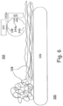
- Fig. 6 depicts a basic embodiment of the instrument 100, where a belt 126 draws the input material 108 past an integration sphere 242a, illumination source 120, and sensor 124, which operate in the manner as described elsewhere herein.
- the preparation module 102 and the control module 106 are not depicted in Fig. 6 , but the preparation module 102, the control module 106 and control lines are used in such an embodiment.
- control module 106 includes hardware to perform at least three functions, which are:
- the controller and signal processor 128, such as a personal computer or other computing device.
- the control functions include, but are not limited to, controlling the drafting operation between the two sets of fiber movements 112 and 118 in the preparation module 102, and controlling the movement of the web of input material 108 through the sensing instrument 104, such as with the fiber movements 126. It also processes the output of sensor 116, and provides feedback control to the drafting operation. Furthermore, it controls the spectral illumination source 120 and the input material fiber movement set 126, and processes the output of the sensors 122 and 124 via a measurement algorithm. The results of the measurement algorithm are communicated by the controller 128 to at least one of a human user interface 130 and a machine interface 132, which in some embodiments includes, but is not limited to, at least one of another type of textile machine.
- the measurement concept is based on the understanding that each different type of material that fibers can be made of, and which may be included in the input material 108, has unique spectral transmissive and reflective signatures, which are used for detecting, differentiating, and measuring the amounts of the different fiber materials in a blend of such in the web that is tested.
- two types of blend ratio measurements can be used:
- the instrument can be trained to determine k j .
- the following example describes a method to determine k f for a two-component blend, such as a blend of cotton-polyester fibers. This method can be expanded to multi-components blends as well.
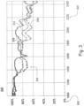
- Fig. 3 depicts a chart 300 for the relative spectral response 302 at different radiation wavelengths 304 (in nm) for natural cotton 306, polyester 308, and a 50-50 blend 310 by weight of cotton-polyester fibers.
- the first part is seeding, which includes collecting and maintaining the spectral signatures of all single components of interest throughout time for different fibers and materials. This can be achieved by either obtaining the spectral signatures from external sources (such as fiber manufacturers) or using the described instrument (during the training process) to create the spectral signatures of all single components of interest. These spectral signatures are maintained in a database, which can be connected to the controller 128 via the information database interface 134 as shown in Fig. 1 .
- the third part is matching criteria, which is a quantified measure of how close an unknown material is to the outcome of the searching process described in the previous step.
- Various mathematical goodness-of-fit measures such as a determination coefficient (R 2 ) or sum of squared errors (SSE), may be used to assess the match for every possible linear combination of components.
- R 2 determination coefficient
- SSE sum of squared errors
Landscapes
- Engineering & Computer Science (AREA)
- Textile Engineering (AREA)
- Chemical & Material Sciences (AREA)
- Health & Medical Sciences (AREA)
- Life Sciences & Earth Sciences (AREA)
- General Health & Medical Sciences (AREA)
- Analytical Chemistry (AREA)
- Biochemistry (AREA)
- Physics & Mathematics (AREA)
- General Physics & Mathematics (AREA)
- Immunology (AREA)
- Pathology (AREA)
- Food Science & Technology (AREA)
- Medicinal Chemistry (AREA)
- Materials Engineering (AREA)
- Mechanical Engineering (AREA)
- Investigating Or Analysing Materials By Optical Means (AREA)
- Treatment Of Fiber Materials (AREA)
Claims (13)
- Messinstrument (100) zum Identifizieren einer Fasermischungszusammensetzung und/oder eines Fasermischungsverhältnisses in einem Fasern enthaltenden Eingangsmaterial (108), wobei das Messinstrument (100) Folgendes umfasst:a. ein Probenabtastmodul (104), umfassend:i. eine Quelle für elektromagnetische Strahlung (120), die an einer zu dem Eingangsmaterial (108) benachbarten Seite angeordnet ist, um einen Strahl elektromagnetischer Strahlung an einer Abtaststelle in dem Probenabtastmodul (104) auf das Eingangsmaterial (108) zu richten, wobei der Strahl elektromagnetischer Strahlung wenigstens zwei deutlich unterschiedliche Wellenlängen des elektromagnetischen Spektrums enthält, undii. einen ersten Sensor für elektromagnetische Strahlung (122), der an einer dem Eingangsmaterial (108) gegenüberliegenden Seite gegenüber der Quelle für elektromagnetische Strahlung (120) angeordnet ist, sodass der erste Sensor für elektromagnetische Strahlung (122) transmittierte Teile des Strahls elektromagnetischer Strahlung, die durch das Eingangsmaterial (108) hindurchgehen, empfangen kann, und/oder einen zweiten Sensor für elektromagnetische Strahlung (124), der an der gleichen Seite des Eingangsmaterials (108) wie die Quelle für elektromagnetische Strahlung (120) angeordnet ist, sodass der zweite Sensor für elektromagnetische Strahlung (124) reflektierte Teile des Strahls elektromagnetischer Strahlung, die von dem Eingangsmaterial (108) reflektiert werden, empfangen kann, wobei der erste Sensor für elektromagnetische Strahlung (122) und/oder der zweite Sensor für elektromagnetische Strahlung (124) jeweils dafür ausgelegt sind, elektromagnetische Strahlung mit wenigstens zwei deutlich unterschiedlichen Wellenlängen des elektromagnetischen Spektrums zu empfangen, undb. ein Steuermodul (106), umfassend eine Steuereinrichtung (128), die dafür ausgelegt ist,i. Datensignale von dem ersten Sensor für elektromagnetische Strahlung (122) und/oder dem zweiten Sensor für elektromagnetische Strahlung (124) zu empfangen,ii. Steuersignale an die Quelle für elektromagnetische Strahlung (120) zu senden, undiii. die Datensignale von dem ersten Sensor für elektromagnetische Strahlung (122) und/oder dem zweiten Sensor für elektromagnetische Strahlung (124) zu verarbeiten, um die Fasermischungszusammensetzung und/oder das Fasermischungsverhältnis in dem Eingangsmaterial (108) zu bestimmen,dadurch gekennzeichnet, dassc. das Probenabtastmodul (104) ferner einen Satz von Faserantriebsmechanismen (126a, 126b) umfasst, um das Eingangsmaterial (108) mit einer Abtastgeschwindigkeit durch das Probenabtastmodul (104) zu ziehen,d. das Messinstrument (100) ferner ein Probenvorbereitungsmodul (102) zum Empfangen und Vorbereiten des Eingangsmaterials (108) umfasst, wobei das Probenvorbereitungsmodul (102) Folgendes umfasst:i. einen ersten vorbereitenden Satz von Faserantriebsmechanismen (112a, 112b) zum Empfangen des Eingangsmaterials (108) und zum Bereitstellen des Eingangsmaterials (108) mit einer vorbereitenden Geschwindigkeit, die kleiner als die oder gleich der Abtastgeschwindigkeit ist,ii. einen zweiten vorbereitenden Satz von Faserantriebsmechanismen (118a, 118b) zum Empfangen des Eingangsmaterials (108) von dem ersten vorbereitenden Satz von Faserantriebsmechanismen (112a, 112b) mit der vorbereitenden Geschwindigkeit und zum Bereitstellen des auf diese Weise empfangenen Eingangsmaterials (108) an das Probenabtastmodul (104) mit der Abtastgeschwindigkeit, wobei ein Unterschied zwischen der vorbereitenden Geschwindigkeit und der Abtastgeschwindigkeit dazu nutzbar ist, eine Dichte des von dem zweiten vorbereitenden Satz von Faserantriebsmechanismen (118a, 118b) bereitgestellten Eingangsmaterials (108) dynamisch anzupassen,iii. eine vorbereitende Quelle für elektromagnetische Strahlung (114), die an einer zu dem Eingangsmaterial (108) benachbarten Seite angeordnet ist, um einen vorbereitenden Strahl elektromagnetischer Strahlung an einer vorbereitenden Stelle zwischen dem ersten vorbereitenden Satz von Faserantriebsmechanismen (112a, 112b) und dem zweiten vorbereitenden Satz von Faserantriebsmechanismen (118a, 118b) in dem Probenvorbereitungsmodul (102) auf das Eingangsmaterial (108) zu richten, undiv. einen vorbereitenden Sensor für elektromagnetische Strahlung (116), der an einer Seite des Eingangsmaterials (108) angeordnet ist, die der vorbereitenden Quelle für elektromagnetische Strahlung (114) gegenüberliegt, sodass der vorbereitende Sensor für elektromagnetische Strahlung (116) vorbereitende transmittierte Teile des vorbereitenden Strahls elektromagnetischer Strahlung, die durch das Eingangsmaterial (108) hindurchgehen, empfangen kann, unde. die Steuereinrichtung (128) ferner dafür ausgelegt ist,i. Datensignale von dem vorbereitenden Sensor für elektromagnetische Strahlung (116) zu empfangen,ii. Steuersignale an die vorbereitende Quelle für elektromagnetische Strahlung (114), den ersten vorbereitenden Satz von Faserantriebsmechanismen (112a, 112b) und den zweiten vorbereitenden Satz von Faserantriebsmechanismen (118a, 118b) zu senden,iii. Steuersignale an den Satz von Faserantriebsmechanismen (126a, 126b) zu senden, undiv. die Datensignale von dem vorbereitenden Sensor für elektromagnetische Strahlung (116) zu verarbeiten und die Steuersignale an den ersten vorbereitenden Satz von Faserantriebsmechanismen (112a, 112b) und den zweiten vorbereitenden Satz von Faserantriebsmechanismen (118a, 118b) anzupassen, um eine gewünschte Dichte an Eingangsmaterial von dem Probenvorbereitungsmodul (102) an das Probenabtastmodul (104) bereitzustellen.
- Messinstrument (100) nach Anspruch 1, ferner umfassend einen Zuführbehälter (110) in dem Probenvorbereitungsmodul (102) zum Aufnehmen des Eingangsmaterials (108) vor der Abgabe des Eingangsmaterials (108) an den ersten vorbereitenden Satz von Faserantriebsmechanismen (112a, 112b).
- Messinstrument (100) nach einem der vorhergehenden Ansprüche, ferner umfassend:einen Quellen-Optiksatz (136) zum Abgeben des Strahls elektromagnetischer Strahlung an das Eingangsmaterial (108), und/odereinen ersten Sensor-Optiksatz (140) zum Abgeben des transmittierten Teils des Strahls elektromagnetischer Strahlung an den ersten Sensor für elektromagnetische Strahlung (122), und/odereinen zweiten Sensor-Optiksatz (138) zum Abgeben des reflektierten Teils des Strahls elektromagnetischer Strahlung an den zweiten Sensor für elektromagnetische Strahlung (124).
- Messinstrument (100) nach einem der vorhergehenden Ansprüche, ferner umfassend eine Maschinenschnittstelle (132) in dem Steuermodul (106), die dafür ausgelegt ist, die Fasermischungszusammensetzung und/oder das Fasermischungsverhältnis an wenigstens eine aus einer Vorverarbeitungseinrichtung und einer Nachverarbeitungseinrichtung zu übermitteln.
- Messinstrument (100) nach einem der vorhergehenden Ansprüche, ferner umfassend eine Informationsdatenbankschnittstelle (134) in dem Steuermodul (106) zum Bereitstellen von Daten zur Transmission und Reflexion elektromagnetischer Strahlung für eine Vielzahl von Fasern an die Steuereinrichtung (128) zur Verwendung bei der Bestimmung der Fasermischungszusammensetzung und/oder des Fasermischungsverhältnisses.
- Messinstrument (100) nach Anspruch 5, wobei die Daten zur Transmission und Reflexion elektromagnetischer Strahlung Daten für synthetische Fasern und für natürliche Fasern umfassen.
- Messinstrument (100) nach einem der vorhergehenden Ansprüche, wobei die spektrale Beleuchtungsquelle (120) eines oder mehreres von Folgendemumfasst: LED, Halogenlampe, Quecksilberdampflampe, Glühlampe, Deuteriumlampe und Xenonlampe.
- Messinstrument (100) nach einem der vorhergehenden Ansprüche, wobei der erste Sensor für elektromagnetische Strahlung (122) und/oder der zweiten Sensor für elektromagnetische Strahlung (124) eines oder mehreres von Folgendem umfassen: ein Spektrometer, eine Photodiode, eine Photodiode, die mit einem Filterrad gekoppelt ist, das Bandpassfilter enthält, eine Anordnung von Photodioden, die jeweils mit Schmalbandfiltern abgedeckt sind, und hyper-spektrale eindimensionale oder zweidimensionale Bildgeber.
- Messinstrument (100) nach einem der vorhergehenden Ansprüche, wobei der erste Sensor für elektromagnetische Strahlung (122) und/oder der zweite Sensor für elektromagnetische Strahlung (124) eine Mehrzahl von Sensoren für elektromagnetische Strahlung (450a, 450b, 450c) umfassen, die entlang einer Oberfläche des Eingangsmaterials an unterschiedlichen Positionen in einer Richtung (Y) senkrecht zur Bewegungsrichtung (X) des Eingangsmaterials (108) angeordnet sind.
- Messinstrument (100) nach einem der vorhergehenden Ansprüche, wobei der erste Sensor für elektromagnetische Strahlung (122, 450d) und/oder der zweite Sensor für elektromagnetische Strahlung (124, 450d) entlang einer Oberfläche des Eingangsmaterials (108) in einer Richtung (Y) senkrecht zur Bewegungsrichtung (X) des Eingangsmaterials (108) beweglich sind.
- Messinstrument (100) nach einem der vorhergehenden Ansprüche, wobei die Faserantriebsmechanismen (112a, 112b; 118a, 118b; 126a, 126b; 126) wenigstens eine Rolle (112a, 112b; 118a, 118b; 126a, 126b) und/oder wenigstens ein Band (126) umfassen.
- Verfahren zum Identifizieren einer Fasermischungszusammensetzung und/oder eines Fasermischungsverhältnisses in einem Fasern enthaltenden Eingangsmaterial (108), wobei das Verfahren die folgenden Schritte umfasst:a.i. Empfangen des Eingangsmaterials (108) mit einem ersten vorbereitenden Satz von Faserantriebsmechanismen (112a, 112b), der sich mit einer vorbereitenden Geschwindigkeit bewegt, die kleiner als die oder gleich der Abtastgeschwindigkeit ist,ii. Empfangen des Eingangsmaterials (108) von dem ersten vorbereitenden Satz von Faserantriebsmechanismen (112a, 112b) mit einem zweiten vorbereitenden Satz von Faserantriebsmechanismen (118a, 118b), der sich mit der Abtastgeschwindigkeit bewegt, wobei ein Unterschied zwischen der vorbereitenden Geschwindigkeit und der Abtastgeschwindigkeit dazu nutzbar ist, eine Dichte des von dem zweiten vorbereitenden Satz von Faserantriebsmechanismen (118a, 118b) bereitgestellten Eingangsmaterials (108) dynamisch anzupassen,iii. Richten eines vorbereitenden Strahls elektromagnetischer Strahlung auf das Eingangsmaterial (108) unter Verwendung einer vorbereitenden Quelle für elektromagnetische Strahlung (114), die auf einer zu dem Eingangsmaterial (108) benachbarten Seite und an einer vorbereitenden Stelle zwischen dem ersten vorbereitenden Satz von Faserantriebsmechanismen (112a, 112b) und dem zweiten vorbereitenden Satz von Faserantriebsmechanismen (118a, 118b) angeordnet ist, undiv. Empfangen von vorbereitenden transmittierten Teilen des vorbereitenden Strahls elektromagnetischer Strahlung, die durch das Eingangsmaterial (108) hindurchgehen, unter Verwendung eines vorbereitenden Sensors für elektromagnetische Strahlung (116), der auf einer Seite des Eingangsmaterials (108) angeordnet ist, die jener der vorbereitenden Quelle für elektromagnetische Strahlung (114) gegenüberliegt,b. Ziehen des Eingangsmaterials (108) mit einer Abtastgeschwindigkeit unter Verwendung eines Satzes von Faserantriebsmechanismen (126a, 126b),c. Richten eines Strahls elektromagnetischer Strahlung auf das Eingangsmaterial (108) an einer Abtaststelle unter Verwendung einer Quelle für elektromagnetische Strahlung (120), die auf einer zu dem Eingangsmaterial (108) benachbarten Seite angeordnet ist, wobei der Strahl elektromagnetischer Strahlung wenigstens zwei deutlich unterschiedliche Wellenlängen des elektromagnetischen Spektrums enthält,d. Empfangen von transmittierten Teilen des Strahls elektromagnetischer Strahlung, die durch das Eingangsmaterial (108) hindurchgehen, unter Verwendung eines ersten Sensors für elektromagnetische Strahlung (122), der an einer dem Eingangsmaterial (108) gegenüberliegenden Seite gegenüber der Quelle für elektromagnetische Strahlung (120) angeordnet ist, und/oder Empfangen von reflektierten Teilen des Strahls elektromagnetischer Strahlung, die von dem Eingangsmaterial (108) reflektiert werden, unter Verwendung eines zweiten Sensors für elektromagnetische Strahlung (124), der an der gleichen Seite des Eingangsmaterials (108) wie die Quelle für elektromagnetische Strahlung (120) angeordnet ist, wobei der erste Sensor für elektromagnetische Strahlung (122) und/oder der zweite Sensor für elektromagnetische Strahlung (124) jeweils dafür ausgelegt sind, elektromagnetische Strahlung mit wenigstens zwei deutlich unterschiedlichen Wellenlängen des elektromagnetischen Spektrums zu empfangen,e. Empfangen von Datensignalen von dem vorbereitenden Sensor für elektromagnetische Strahlung (116) und von dem ersten Sensor für elektromagnetische Strahlung (122) und/oder dem zweiten Sensor für elektromagnetische Strahlung (124),f. Senden von Steuersignalen an die vorbereitende Quelle für elektromagnetische Strahlung (114), den ersten vorbereitenden Satz von Faserantriebsmechanismen (112a, 112b), den zweiten vorbereitenden Satz von Faserantriebsmechanismen (118a, 118b), die Quelle für elektromagnetische Strahlung (120) und den Satz von Faserantriebsmechanismen (126a, 126b),g. Verarbeiten der Datensignale von dem vorbereitenden Sensor für elektromagnetische Strahlung (116) und Anpassen der Steuersignale an den ersten vorbereitenden Satz von Faserantriebsmechanismen (112a, 112b) und den zweiten vorbereitenden Satz von Faserantriebsmechanismen (118a, 118b), um eine gewünschte Dichte des Eingangsmaterials (108) an der Abtaststelle bereitzustellen, undh. Verarbeiten der Datensignale von dem ersten Sensor für elektromagnetische Strahlung (122) und/oder dem zweiten Sensor für elektromagnetische Strahlung (124), um die Fasermischungszusammensetzung und/oder das Fasermischungsverhältnis im Eingangsmaterial (108) zu bestimmen.
- Verfahren nach Anspruch 12, ferner umfassend das Übermitteln der Fasermischungszusammensetzung und/oder des Fasermischungsverhältnisses an wenigstens eine aus einer Vorverarbeitungseinrichtung und einer Nachverarbeitungseinrichtung.
Applications Claiming Priority (2)
| Application Number | Priority Date | Filing Date | Title |
|---|---|---|---|
| US201762558506P | 2017-09-14 | 2017-09-14 | |
| PCT/CH2018/000038 WO2019051620A1 (en) | 2017-09-14 | 2018-09-11 | IDENTIFICATION AND / OR MEASUREMENT OF FIBER MIXING RATIO |
Publications (2)
| Publication Number | Publication Date |
|---|---|
| EP3662283A1 EP3662283A1 (de) | 2020-06-10 |
| EP3662283B1 true EP3662283B1 (de) | 2025-07-02 |
Family
ID=63832158
Family Applications (1)
| Application Number | Title | Priority Date | Filing Date |
|---|---|---|---|
| EP18785247.0A Active EP3662283B1 (de) | 2017-09-14 | 2018-09-11 | Fasermischungsidentifizierung und/oder -messung |
Country Status (4)
| Country | Link |
|---|---|
| US (1) | US11402335B2 (de) |
| EP (1) | EP3662283B1 (de) |
| CN (1) | CN111133310B (de) |
| WO (1) | WO2019051620A1 (de) |
Families Citing this family (7)
| Publication number | Priority date | Publication date | Assignee | Title |
|---|---|---|---|---|
| CN117242332A (zh) * | 2021-03-26 | 2023-12-15 | 乌斯特技术股份公司 | 检测纺织纤维结构中两种成分的混合比例 |
| EP4419907A4 (de) * | 2021-10-18 | 2025-08-27 | Refiberd Inc | Intelligente erkennung der faserzusammensetzung von textilien durch automatisierte analyse durch maschinenlernmodelle |
| WO2024031201A1 (de) * | 2022-08-08 | 2024-02-15 | Uster Technologies Ag | Untersuchung eines zwei bestandteile enthaltenden textilen fasergebildes |
| US12029537B2 (en) * | 2022-08-23 | 2024-07-09 | Samsung Electronics Co., Ltd | Polarized photoplethysmography (PPG) biosensors, arrays and systems |
| CH720833A1 (de) * | 2023-06-06 | 2024-12-13 | Rieter Ag Maschf | Verfahren zur Kontrolle und Einstellung der Fasermischung einer Faservorbereitungsmaschine |
| LU505551B1 (en) * | 2023-11-16 | 2025-05-19 | Saurer Intelligent Technology AG | Illumination receiving system and method for measuring |
| LU505549B1 (en) * | 2023-11-16 | 2025-05-19 | Saurer Intelligent Technology AG | Illumination projector, method of manufacturing and method of projection |
Family Cites Families (34)
| Publication number | Priority date | Publication date | Assignee | Title |
|---|---|---|---|---|
| BE704412A (de) * | 1967-09-28 | 1968-02-01 | ||
| GB2095828B (en) * | 1981-03-31 | 1985-12-18 | Wool Dev Int | Detection of defects in fibrous arrays |
| US5270787A (en) | 1990-03-14 | 1993-12-14 | Zellweger Uster Inc. | Electro-optical methods and apparatus for high speed, multivariate measurement of individual entities in fiber or other samples |
| US5321496A (en) | 1990-03-14 | 1994-06-14 | Zellweger Uster, Inc. | Apparatus for monitoring trash in a fiber sample |
| DE59108679D1 (de) * | 1990-11-02 | 1997-05-28 | Rieter Ag Maschf | Verfahren zum Feststellen einer Eigenschaft eines Faserverbandes |
| EP0602145B1 (de) | 1991-09-06 | 1999-03-03 | Commonwealth Scientific And Industrial Research Organisation | Messverfahren und -vorrichtung |
| DE4131664A1 (de) * | 1991-09-23 | 1993-03-25 | Rieter Ingolstadt Spinnerei | Verfahren und vorrichtung zum erfassen von garnfehlern |
| CH683293A5 (de) * | 1991-12-20 | 1994-02-15 | Peyer Ag Siegfried | Fremdfasererkennung in Garnen. |
| CH683035A5 (de) * | 1992-01-31 | 1993-12-31 | Loepfe Ag Geb | Verfahren und Vorrichtung zur Detektion von Verunreinigungen, insbesondere Fremdfasern in langgestreckten, textilen Gebilden. |
| CH683378A5 (de) * | 1992-03-17 | 1994-02-28 | Zellweger Uster Ag | Verfahren und Vorrichtung zur Detektion von Verunreinigungen in einem textilen Prüfgut sowie Verwendung der Vorrichtung. |
| US5311290A (en) | 1992-09-30 | 1994-05-10 | Pulp And Paper Research Institute Of Canada | Imaging apparatus and method of fiber analysis |
| US5367747A (en) | 1992-12-31 | 1994-11-29 | Zellweger Uster, Inc. | Needle-based apparatus for individualizing fibers and other textile entities for testing purposes |
| DE69324557T2 (de) * | 1992-12-31 | 1999-09-23 | Zellweger Uster, Inc. | Kontinuierliche zweidimensionale Überwachung von dünnem Gewebe textilen Materials |
| JPH07120375A (ja) | 1993-10-21 | 1995-05-12 | Hitachi Ltd | フロー式粒子画像解析方法及び装置 |
| EP0652432A1 (de) | 1993-11-04 | 1995-05-10 | BARCO nv/Automation | Vorrichtung zum Erkennen von Fremdmaterial, insbesondere von Fremdfasern, in einem längsbewegten textilen Gebilde |
| AUPM533094A0 (en) | 1994-04-27 | 1994-05-19 | Commonwealth Scientific And Industrial Research Organisation | Methods and apparatus for determining a first parameter(s) of an object |
| US5786894A (en) | 1996-10-25 | 1998-07-28 | International Paper Company | Measurement of paper pulp and fiber visual characteristics |
| AU2828699A (en) | 1998-01-22 | 1999-08-09 | Maschinenfabrik Rieter A.G. | Method and device for measuring fibre length |
| US5991046A (en) * | 1998-07-14 | 1999-11-23 | Valmet Automation Inc. | Method and apparatus for optically measuring properties of a moving web |
| US6040905A (en) | 1998-08-05 | 2000-03-21 | Zellweger Uster, Inc. | Fiber color grading system |
| DE19939711B4 (de) * | 1999-08-21 | 2015-03-12 | Saurer Germany Gmbh & Co. Kg | Verfahren und Vorrichtung zur Detektierung von Fremdkörpern in einem längsbewegten Faden |
| DE10009131A1 (de) * | 2000-02-26 | 2001-08-30 | Schlafhorst & Co W | Verfahren und Vorrichtung zur optischen Detektion von Verunreinigungen, insbesondere Fremdfasern, in längsbewegten Garn |
| JP4811813B2 (ja) * | 2000-05-31 | 2011-11-09 | ウステル・テヒノロジーズ・アクチエンゲゼルシヤフト | 長手方向に動かされる糸状製品中の夾雑物を確認する方法及び装置 |
| WO2002035308A2 (en) * | 2000-10-23 | 2002-05-02 | Am Vision Technologies Ltd. | Method and device for optically determining bulk density and uniformity of web configured material during in-line processing |
| JP2004535582A (ja) * | 2001-07-12 | 2004-11-25 | ウステル・テヒノロジーズ・アクチエンゲゼルシヤフト | 繊維材料中の夾雑物を識別する方法及び装置 |
| US7307729B2 (en) * | 2002-08-19 | 2007-12-11 | Green Vision Systems Ltd. | Electro-optically inspecting and determining internal properties and characteristics of a longitudinally moving rod of material |
| AU2003222403A1 (en) | 2003-03-28 | 2004-10-18 | Premier Polytronics, Pvt. Ltd. | Automatic fiber processing system including method and apparatus for producing end-aligned fiber samples |
| DE102004030967A1 (de) | 2004-06-26 | 2006-01-12 | Trützschler GmbH & Co KG | Vorrichtung zur Messung der Masse eines eine Spinnereivorbereitungsmaschine oder -anlage durchlaufenden Fasermaterials |
| US7880156B2 (en) * | 2006-12-27 | 2011-02-01 | Honeywell International Inc. | System and method for z-structure measurements using simultaneous multi-band tomography |
| CN101246121B (zh) * | 2008-03-21 | 2010-09-08 | 东华大学 | 一种基于偏振光显微镜的纱线成分检测方法 |
| CH699219A1 (de) * | 2008-07-25 | 2010-01-29 | Uster Technologies Ag | Verfahren und Vorrichtung zur Garnreinigung. |
| EP2730914B1 (de) * | 2011-10-28 | 2016-07-13 | Toray Industries, Inc. | Verfahren zur herstellung von prepreg |
| FR3005042B1 (fr) * | 2013-04-26 | 2016-01-01 | Snecma | Machine a tisser ou enrouler une texture fibreuse permettant un controle d'anomalies par analyse d'images |
| CN104865218B (zh) * | 2015-05-06 | 2017-06-23 | 江西出入境检验检疫局检验检疫综合技术中心 | 快速测定棉麻混纺纤维含量的方法 |
-
2018
- 2018-09-11 US US16/644,845 patent/US11402335B2/en active Active
- 2018-09-11 CN CN201880057493.9A patent/CN111133310B/zh active Active
- 2018-09-11 WO PCT/CH2018/000038 patent/WO2019051620A1/en not_active Ceased
- 2018-09-11 EP EP18785247.0A patent/EP3662283B1/de active Active
Also Published As
| Publication number | Publication date |
|---|---|
| CN111133310B (zh) | 2023-01-24 |
| US11402335B2 (en) | 2022-08-02 |
| WO2019051620A1 (en) | 2019-03-21 |
| EP3662283A1 (de) | 2020-06-10 |
| CN111133310A (zh) | 2020-05-08 |
| US20210199593A1 (en) | 2021-07-01 |
Similar Documents
| Publication | Publication Date | Title |
|---|---|---|
| EP3662283B1 (de) | Fasermischungsidentifizierung und/oder -messung | |
| EP0758083B1 (de) | Vorrichtung zur spektralen Remissions- und Transmissionsmessung | |
| CN101784883B (zh) | 用于纤维网的制造的电磁检测方法和装置 | |
| US20030038938A1 (en) | Apparatus and method for measuring optical characteristics of an object or material | |
| US20020001078A1 (en) | Optical measuring arrangement, in particular for quality control in continuous processes | |
| EP1242811B1 (de) | Verfahren und vorrichtung zum kontrollieren der herstellungsqualität einer bewegten bahn | |
| WO2005038443A1 (ja) | 平面分光器を用いた異種品検出装置 | |
| CN106959307A (zh) | 测量纺织纤维含水量、长度和测力特征的测量方法和装置 | |
| EP1624302A2 (de) | Messen und Testen kontinuierlichen länglichen Textilmaterials | |
| JP2013044729A (ja) | 塗布状態測定方法 | |
| EP2475978A1 (de) | Vorrichtung und verfahren zur optischen abtastung eines bewegten textilmaterials | |
| EP1907830B1 (de) | Nachweis von fremdstoffen in einem textilmaterial | |
| ITTO950796A1 (it) | Procedimento e sistema per rilevare parametri chimico-fisici. | |
| Montalvo Jr et al. | Analysis of cotton | |
| US20240175806A1 (en) | Detecting a Mixture Ratio of Two Components of a Textile Fiber Structure | |
| DE102017108552A1 (de) | Spektrometrischer Messkopf mit mehreren Transmissionslicht-Eintrittsfenstern | |
| ITMI20001954A1 (it) | Dispositivo di una carda o macchina cardatrice, in qui e' formato un pelo fibroso da fibre tessili, per esempio cotone, fibre chimiche e sim | |
| KR20010101831A (ko) | 폴리에틸렌 테레프탈레이트 섬유의 염착량 측정방법 | |
| Ghosh | On-line measurement of polyvinyl alcohol size on warp yarns using a near-IR diffuse reflectance spectroscopy method | |
| DE29512646U1 (de) | Vorrichtung zur spektralen Farbwertemessung | |
| CN113970522B (zh) | 一种在线分析用于生产吸收性卫生用品的机器中的复合产品的方法 | |
| JP2005321349A (ja) | 材質判断装置 | |
| EP4314769B1 (de) | Optische vorrichtung | |
| EP1247078A4 (de) | Vorrichtung und verfahren zur messung optischer eigenschaften eines objekts oder materials | |
| WO2011086380A2 (en) | Spectrometric characterization of heterogeneity |
Legal Events
| Date | Code | Title | Description |
|---|---|---|---|
| STAA | Information on the status of an ep patent application or granted ep patent |
Free format text: STATUS: UNKNOWN |
|
| STAA | Information on the status of an ep patent application or granted ep patent |
Free format text: STATUS: THE INTERNATIONAL PUBLICATION HAS BEEN MADE |
|
| PUAI | Public reference made under article 153(3) epc to a published international application that has entered the european phase |
Free format text: ORIGINAL CODE: 0009012 |
|
| STAA | Information on the status of an ep patent application or granted ep patent |
Free format text: STATUS: REQUEST FOR EXAMINATION WAS MADE |
|
| 17P | Request for examination filed |
Effective date: 20200128 |
|
| AK | Designated contracting states |
Kind code of ref document: A1 Designated state(s): AL AT BE BG CH CY CZ DE DK EE ES FI FR GB GR HR HU IE IS IT LI LT LU LV MC MK MT NL NO PL PT RO RS SE SI SK SM TR |
|
| AX | Request for extension of the european patent |
Extension state: BA ME |
|
| DAV | Request for validation of the european patent (deleted) | ||
| DAX | Request for extension of the european patent (deleted) | ||
| STAA | Information on the status of an ep patent application or granted ep patent |
Free format text: STATUS: EXAMINATION IS IN PROGRESS |
|
| 17Q | First examination report despatched |
Effective date: 20220804 |
|
| REG | Reference to a national code |
Ref country code: DE Ref legal event code: R079 Free format text: PREVIOUS MAIN CLASS: G01N0033360000 Ipc: D01G0031000000 Ref document number: 602018083216 Country of ref document: DE |
|
| RIC1 | Information provided on ipc code assigned before grant |
Ipc: G01N 21/89 20060101ALI20230822BHEP Ipc: D06H 3/00 20060101ALI20230822BHEP Ipc: G01N 33/36 20060101ALI20230822BHEP Ipc: D01H 13/32 20060101ALI20230822BHEP Ipc: D01G 31/00 20060101AFI20230822BHEP |
|
| GRAP | Despatch of communication of intention to grant a patent |
Free format text: ORIGINAL CODE: EPIDOSNIGR1 |
|
| STAA | Information on the status of an ep patent application or granted ep patent |
Free format text: STATUS: GRANT OF PATENT IS INTENDED |
|
| INTG | Intention to grant announced |
Effective date: 20241206 |
|
| GRAJ | Information related to disapproval of communication of intention to grant by the applicant or resumption of examination proceedings by the epo deleted |
Free format text: ORIGINAL CODE: EPIDOSDIGR1 |
|
| STAA | Information on the status of an ep patent application or granted ep patent |
Free format text: STATUS: EXAMINATION IS IN PROGRESS |
|
| INTC | Intention to grant announced (deleted) | ||
| GRAP | Despatch of communication of intention to grant a patent |
Free format text: ORIGINAL CODE: EPIDOSNIGR1 |
|
| STAA | Information on the status of an ep patent application or granted ep patent |
Free format text: STATUS: GRANT OF PATENT IS INTENDED |
|
| INTG | Intention to grant announced |
Effective date: 20250331 |
|
| GRAS | Grant fee paid |
Free format text: ORIGINAL CODE: EPIDOSNIGR3 |
|
| GRAA | (expected) grant |
Free format text: ORIGINAL CODE: 0009210 |
|
| STAA | Information on the status of an ep patent application or granted ep patent |
Free format text: STATUS: THE PATENT HAS BEEN GRANTED |
|
| AK | Designated contracting states |
Kind code of ref document: B1 Designated state(s): AL AT BE BG CH CY CZ DE DK EE ES FI FR GB GR HR HU IE IS IT LI LT LU LV MC MK MT NL NO PL PT RO RS SE SI SK SM TR |
|
| REG | Reference to a national code |
Ref country code: GB Ref legal event code: FG4D |
|
| REG | Reference to a national code |
Ref country code: CH Ref legal event code: EP |
|
| REG | Reference to a national code |
Ref country code: DE Ref legal event code: R096 Ref document number: 602018083216 Country of ref document: DE |
|
| REG | Reference to a national code |
Ref country code: IE Ref legal event code: FG4D |
|
| REG | Reference to a national code |
Ref country code: CH Ref legal event code: U11 Free format text: ST27 STATUS EVENT CODE: U-0-0-U10-U11 (AS PROVIDED BY THE NATIONAL OFFICE) Effective date: 20251015 |
|
| REG | Reference to a national code |
Ref country code: NL Ref legal event code: MP Effective date: 20250702 |
|
| PG25 | Lapsed in a contracting state [announced via postgrant information from national office to epo] |
Ref country code: PT Free format text: LAPSE BECAUSE OF FAILURE TO SUBMIT A TRANSLATION OF THE DESCRIPTION OR TO PAY THE FEE WITHIN THE PRESCRIBED TIME-LIMIT Effective date: 20251103 |
|
| PG25 | Lapsed in a contracting state [announced via postgrant information from national office to epo] |
Ref country code: NL Free format text: LAPSE BECAUSE OF FAILURE TO SUBMIT A TRANSLATION OF THE DESCRIPTION OR TO PAY THE FEE WITHIN THE PRESCRIBED TIME-LIMIT Effective date: 20250702 |
|
| REG | Reference to a national code |
Ref country code: AT Ref legal event code: MK05 Ref document number: 1809347 Country of ref document: AT Kind code of ref document: T Effective date: 20250702 |
|
| PG25 | Lapsed in a contracting state [announced via postgrant information from national office to epo] |
Ref country code: IS Free format text: LAPSE BECAUSE OF FAILURE TO SUBMIT A TRANSLATION OF THE DESCRIPTION OR TO PAY THE FEE WITHIN THE PRESCRIBED TIME-LIMIT Effective date: 20251102 |
|
| PGFP | Annual fee paid to national office [announced via postgrant information from national office to epo] |
Ref country code: DE Payment date: 20250929 Year of fee payment: 8 |
|
| PG25 | Lapsed in a contracting state [announced via postgrant information from national office to epo] |
Ref country code: NO Free format text: LAPSE BECAUSE OF FAILURE TO SUBMIT A TRANSLATION OF THE DESCRIPTION OR TO PAY THE FEE WITHIN THE PRESCRIBED TIME-LIMIT Effective date: 20251002 |
|
| REG | Reference to a national code |
Ref country code: LT Ref legal event code: MG9D |
|
| PG25 | Lapsed in a contracting state [announced via postgrant information from national office to epo] |
Ref country code: AT Free format text: LAPSE BECAUSE OF FAILURE TO SUBMIT A TRANSLATION OF THE DESCRIPTION OR TO PAY THE FEE WITHIN THE PRESCRIBED TIME-LIMIT Effective date: 20250702 |
|
| PG25 | Lapsed in a contracting state [announced via postgrant information from national office to epo] |
Ref country code: FI Free format text: LAPSE BECAUSE OF FAILURE TO SUBMIT A TRANSLATION OF THE DESCRIPTION OR TO PAY THE FEE WITHIN THE PRESCRIBED TIME-LIMIT Effective date: 20250702 |
|
| PGFP | Annual fee paid to national office [announced via postgrant information from national office to epo] |
Ref country code: IT Payment date: 20251030 Year of fee payment: 8 |
|
| PG25 | Lapsed in a contracting state [announced via postgrant information from national office to epo] |
Ref country code: HR Free format text: LAPSE BECAUSE OF FAILURE TO SUBMIT A TRANSLATION OF THE DESCRIPTION OR TO PAY THE FEE WITHIN THE PRESCRIBED TIME-LIMIT Effective date: 20250702 |
|
| PG25 | Lapsed in a contracting state [announced via postgrant information from national office to epo] |
Ref country code: GR Free format text: LAPSE BECAUSE OF FAILURE TO SUBMIT A TRANSLATION OF THE DESCRIPTION OR TO PAY THE FEE WITHIN THE PRESCRIBED TIME-LIMIT Effective date: 20251003 |
|
| PGFP | Annual fee paid to national office [announced via postgrant information from national office to epo] |
Ref country code: CH Payment date: 20251015 Year of fee payment: 8 |
|
| PG25 | Lapsed in a contracting state [announced via postgrant information from national office to epo] |
Ref country code: SE Free format text: LAPSE BECAUSE OF FAILURE TO SUBMIT A TRANSLATION OF THE DESCRIPTION OR TO PAY THE FEE WITHIN THE PRESCRIBED TIME-LIMIT Effective date: 20250702 Ref country code: CZ Free format text: LAPSE BECAUSE OF FAILURE TO SUBMIT A TRANSLATION OF THE DESCRIPTION OR TO PAY THE FEE WITHIN THE PRESCRIBED TIME-LIMIT Effective date: 20250702 |
|
| PG25 | Lapsed in a contracting state [announced via postgrant information from national office to epo] |
Ref country code: LV Free format text: LAPSE BECAUSE OF FAILURE TO SUBMIT A TRANSLATION OF THE DESCRIPTION OR TO PAY THE FEE WITHIN THE PRESCRIBED TIME-LIMIT Effective date: 20250702 |
|
| PG25 | Lapsed in a contracting state [announced via postgrant information from national office to epo] |
Ref country code: PL Free format text: LAPSE BECAUSE OF FAILURE TO SUBMIT A TRANSLATION OF THE DESCRIPTION OR TO PAY THE FEE WITHIN THE PRESCRIBED TIME-LIMIT Effective date: 20250702 Ref country code: BG Free format text: LAPSE BECAUSE OF FAILURE TO SUBMIT A TRANSLATION OF THE DESCRIPTION OR TO PAY THE FEE WITHIN THE PRESCRIBED TIME-LIMIT Effective date: 20250702 |
|
| PG25 | Lapsed in a contracting state [announced via postgrant information from national office to epo] |
Ref country code: RS Free format text: LAPSE BECAUSE OF FAILURE TO SUBMIT A TRANSLATION OF THE DESCRIPTION OR TO PAY THE FEE WITHIN THE PRESCRIBED TIME-LIMIT Effective date: 20251002 |
|
| PG25 | Lapsed in a contracting state [announced via postgrant information from national office to epo] |
Ref country code: ES Free format text: LAPSE BECAUSE OF FAILURE TO SUBMIT A TRANSLATION OF THE DESCRIPTION OR TO PAY THE FEE WITHIN THE PRESCRIBED TIME-LIMIT Effective date: 20250702 |
|
| PG25 | Lapsed in a contracting state [announced via postgrant information from national office to epo] |
Ref country code: RO Free format text: LAPSE BECAUSE OF FAILURE TO SUBMIT A TRANSLATION OF THE DESCRIPTION OR TO PAY THE FEE WITHIN THE PRESCRIBED TIME-LIMIT Effective date: 20250702 |