EP3662283B1 - Fiber blend identification and/or ratio measurement - Google Patents
Fiber blend identification and/or ratio measurement Download PDFInfo
- Publication number
- EP3662283B1 EP3662283B1 EP18785247.0A EP18785247A EP3662283B1 EP 3662283 B1 EP3662283 B1 EP 3662283B1 EP 18785247 A EP18785247 A EP 18785247A EP 3662283 B1 EP3662283 B1 EP 3662283B1
- Authority
- EP
- European Patent Office
- Prior art keywords
- electromagnetic radiation
- preparatory
- input material
- fiber
- radiation sensor
- Prior art date
- Legal status (The legal status is an assumption and is not a legal conclusion. Google has not performed a legal analysis and makes no representation as to the accuracy of the status listed.)
- Active
Links
Images


Classifications
-
- D—TEXTILES; PAPER
- D01—NATURAL OR MAN-MADE THREADS OR FIBRES; SPINNING
- D01G—PRELIMINARY TREATMENT OF FIBRES, e.g. FOR SPINNING
- D01G31/00—Warning or safety devices, e.g. automatic fault detectors, stop motions
- D01G31/006—On-line measurement and recording of process and product parameters
-
- D—TEXTILES; PAPER
- D01—NATURAL OR MAN-MADE THREADS OR FIBRES; SPINNING
- D01H—SPINNING OR TWISTING
- D01H13/00—Other common constructional features, details or accessories
- D01H13/32—Counting, measuring, recording or registering devices
-
- D—TEXTILES; PAPER
- D06—TREATMENT OF TEXTILES OR THE LIKE; LAUNDERING; FLEXIBLE MATERIALS NOT OTHERWISE PROVIDED FOR
- D06H—MARKING, INSPECTING, SEAMING OR SEVERING TEXTILE MATERIALS
- D06H3/00—Inspecting textile materials
-
- D—TEXTILES; PAPER
- D06—TREATMENT OF TEXTILES OR THE LIKE; LAUNDERING; FLEXIBLE MATERIALS NOT OTHERWISE PROVIDED FOR
- D06H—MARKING, INSPECTING, SEAMING OR SEVERING TEXTILE MATERIALS
- D06H3/00—Inspecting textile materials
- D06H3/16—Inspecting hosiery or other tubular fabric; Inspecting in combination with turning inside-out, classifying, or other handling
- D06H3/165—Devices for supplying, removing or stacking the work
-
- G—PHYSICS
- G01—MEASURING; TESTING
- G01N—INVESTIGATING OR ANALYSING MATERIALS BY DETERMINING THEIR CHEMICAL OR PHYSICAL PROPERTIES
- G01N21/00—Investigating or analysing materials by the use of optical means, i.e. using sub-millimetre waves, infrared, visible or ultraviolet light
- G01N21/84—Systems specially adapted for particular applications
- G01N21/88—Investigating the presence of flaws or contamination
- G01N21/89—Investigating the presence of flaws or contamination in moving material, e.g. running paper or textiles
- G01N21/8914—Investigating the presence of flaws or contamination in moving material, e.g. running paper or textiles characterised by the material examined
- G01N21/8915—Investigating the presence of flaws or contamination in moving material, e.g. running paper or textiles characterised by the material examined non-woven textile material
-
- G—PHYSICS
- G01—MEASURING; TESTING
- G01N—INVESTIGATING OR ANALYSING MATERIALS BY DETERMINING THEIR CHEMICAL OR PHYSICAL PROPERTIES
- G01N33/00—Investigating or analysing materials by specific methods not covered by groups G01N1/00 - G01N31/00
- G01N33/36—Textiles
- G01N33/365—Filiform textiles, e.g. yarns
Definitions
- This invention relates to the field of textile fiber characteristic measurement. More particularly, this invention relates to measurement of blended textile fiber characteristics. Even more particularly, it relates to a measurement instrument for identifying fiber blend composition and/or fiber blend ratio in an input material comprising fibers, and to a method for identifying fiber blend composition and/or fiber blend ratio in an input material comprising fibers.
- Textile fiber is the raw material for making textiles or textile intermediate products, such as yarn and fabric. Historically, cotton and other natural fibers have been the most important and utilized textile raw material. In recent years, however, synthetic or manmade fibers have gained popularity and utilization. As the name implies, synthetic fibers such as polyester and rayon are made artificially using chemical process.
- Blends may offer a cost and performance advantage that might not be matched by cotton alone for a given application. In such case, the choice of fiber type and the ratio of different fiber types (blend ratio) in the blend plays an important role in cost and performance of the yarn produced.
- the current blend ratio measurement method is based on chemical techniques where a blend sample is initially weighed and then weighed again, sometimes iteratively so, after chemically removing each of the blend components one at a time (in those cases where more than one additional component is present). This is an offline and time-consuming method.
- US-5,355,561 describes measuring a characteristic of a sliver to determine fiber blend. However, the fibers must be compressed at the location where they pass a commercially available measuring instrument.
- US-5,270,787 describes electro-optical measurement of individual entities in fibers that are delivered one at a time to a fluid stream. Each fiber is generally parallel with the direction of fluid flow.
- a sensor senses data such as the speed of the entity, length, fiber ribbon width, fineness, cross-sectional area, maturity, cross-sectional circularity, shape, surface roughness, etc.
- Optical filtering provides information about composition (natural or man-made) and appearance (color and polarization). However, additional, simpler, or other characteristics of fiber blend composition are desired.
- WO-93/13407 A1 relates to a process and device for detecting foreign fibers in a moving yarn.
- Modulated light is directed from a light source at a fixed position on the moving yarn.
- a first sensor receives the light reflected from the yarn and a second sensor receives the light transmitted by the yarn at the same time.
- a first embodiment comprises a single polychromatic light source and two sensors receiving different light wavelengths each.
- a second embodiment comprises several light sources emitting different light wavelengths and two sensors each detecting all of the wavelengths emitted by the multiple light sources.
- the electric signals emitted by the sensors are processed by electronic means in such a way that there is a signal at an output if there is a foreign fiber at the fixed position in the yarn.
- the measurement instrument has a sample sensing module and a control module.
- the sample sensing module comprises a set of fiber movements for drawing the input material through the sample sensing module at a sensing speed.
- the sample sensing module further comprises an electromagnetic radiation source disposed on an adjacent side of the input material for directing a beam of electromagnetic radiation toward the input material at a sensing location within the sample sensing module, the beam of electromagnetic radiation containing at least two clearly distinct wavelengths of the electromagnetic spectrum.
- the sample sensing module further comprises a first electromagnetic radiation sensor disposed on an opposite side of the input material opposite the electromagnetic radiation source such that the first electromagnetic radiation sensor can receive transmitted portions of the beam of electromagnetic radiation that pass through the input material, and/or a second electromagnetic radiation sensor disposed on a same side of the input material as the electromagnetic radiation source such that the second electromagnetic radiation sensor can receive reflected portions of the beam of electromagnetic radiation that reflect off of the input material, wherein the second and/or the second electromagnetic radiation sensor are each configured to receive electromagnetic radiation at at least two clearly distinct wavelengths of the electromagnetic spectrum.
- the control module comprises a controller configured for receiving data signals from the first electromagnetic radiation sensor and/or the second electromagnetic radiation sensor, sending control signals to the electromagnetic radiation source and the set of fiber movements, and processing the data signals from the first electromagnetic radiation sensor and/or the second electromagnetic radiation sensor to determine the fiber blend composition and/or the fiber blend ratio in the input material.
- the measurement instrument further comprises a sample preparation module for receiving and preparing the input material.
- the sample preparation module comprises a first preparatory set of fiber movements for receiving the input material and providing the input material at a preparatory speed that is less than or equal to the sensing speed
- the sample preparation module further comprises a second preparatory set of fiber movements for receiving the input material from the first preparatory set of fiber movements at the preparatory speed and providing the input material so received to the sample sensing module at the sensing speed, whereby a differential between the preparatory speed and the sensing speed is operable to dynamically adjust a density of the input material provided by the second preparatory set of fiber movements.
- the sample preparation module further comprises a preparatory electromagnetic radiation source disposed on a side adjacent the input material for directing a preparatory beam of electromagnetic radiation toward the input material at a preparatory location between the first preparatory set of fiber movements and the second preparatory set of fiber movements within the sample preparation module.
- the sample preparation module further comprises a preparatory electromagnetic radiation sensor disposed on an opposite side of the input material from the preparatory electromagnetic radiation source such that the preparatory electromagnetic radiation sensor can receive preparatory transmitted portions of the preparatory beam of electromagnetic radiation that pass through the input material.
- the controller of this embodiment is further configured for receiving data signals from the preparatory electromagnetic radiation sensor, sending control signals to the preparatory electromagnetic radiation source, the first preparatory set of fiber movements, and the second preparatory set of fiber movements, and processing the data signals from the preparatory electromagnetic radiation sensor and adjusting the control signals to the first preparatory set of fiber movements and the second preparatory set of fiber movements to provide a desired density of input material from the sample preparation module to the sample sensing module.
- the measurement instrument further comprises a hopper in the sample preparation module for holding the input material prior to delivery of the input material to the first preparatory set of fiber movements.
- the measurement instrument further comprises a source set of optics for delivering the beam of electromagnetic radiation to the input material.
- the measurement instrument further comprises a machine interface in the control module configured for communicating the fiber blend composition and/or the fiber blend ratio to at least one of prior processing equipment and post processing equipment.
- the machine interface in the control module can be configured for communicating the fiber blend composition and/or the fiber blend ratio to a prior fiber blending machine.
- the measurement instrument further comprises an information database in the control module for providing electromagnetic radiation transmission and reflectance data for a variety of fibers to the controller for use in determining fiber blend composition and/or fiber blend ratio.
- the electromagnetic radiation transmission and reflectance data can comprise data for manmade fibers and for natural fibers.
- the spectral illumination source comprises one or more of LED, halogen lamp, mercury vapor lamp, incandescent lamp, deuterium lamp, and xenon lamp.
- the first electromagnetic radiation sensor and/or the second electromagnetic radiation sensor comprise one or more of a spectrometer, photodiode, photodiode coupled with filter-wheel including band pass filters, photodiode array, each covered by narrow band filters, and hyper-spectral one-dimensional or two-dimensional imagers.
- the first electromagnetic radiation sensor and/or the second electromagnetic radiation sensor comprises a plurality of electromagnetic radiation sensors disposed at differing positions along a surface of the input material in a direction perpendicular to the direction of movement of the input material.
- the first electromagnetic radiation sensor and/or the second electromagnetic radiation sensor is movable along a surface of the input material in a direction perpendicular to the direction of movement of the input material.
- the fiber movements comprise at least one roller and/or at least one belt.
- the method for identifying fiber blend composition and/or fiber blend ratio in an input material comprising fibers comprises the steps of:
- the method further comprises communicating the fiber blend composition and/or the fiber blend ratio to at least one of prior processing equipment and post processing equipment.
- the fiber blend composition and/or the fiber blend ratio can be communicated to a prior fiber blending machine.
- the first electromagnetic radiation sensor and/or the second electromagnetic radiation sensor comprises a plurality of electromagnetic radiation sensors disposed at differing positions along a surface of the input material in a direction perpendicular to the direction of movement of the input material.
- the method further comprises moving the first electromagnetic radiation sensor and/or the second electromagnetic radiation sensor along a surface of the input material in a direction perpendicular to the direction of movement of the input material.
- Fig. 1 there is depicted a functional block diagram of a blend ratio measurement instrument 100 according to an embodiment of the present invention.
- the measurement instrument 100 as described herein can be used for either online or offline measurement.
- the measurement instrument 100 includes the following modules:
- Fig. 1 also depicts the main components of the measurement instrument 100, including the following:
- the preparation module 102 brings the fibrous input material 108 into the measurement instrument 100 and prepares the input material 108 for presentation to the sensors 116, 122, and 124, as described in more detail below.
- the input hopper 110 receives the input material 108 in batch form and provides it to the first set of input fiber movements 112, and in other embodiments the input material 108 is received by the first preparatory set of fiber movements 112 in a continuous feed, such as a sliver.
- the input material 108 can be received in various formats, such as bale, carding mat, sliver, and so forth.
- the preparation module 102 converts the input material 108 to a web format, such as a sliver, if it is not already presented as such.
- One form is to present each fiber in the input material 108 to the sensors 116, 122, and 124 in an individualized form, and the other form is to present the input material 108 in the web format, which in some embodiments is of a consistent density, as described in more detail below.
- One way to achieve these various forms is by having variably-controlled drafting between the first preparatory set of fiber movements 112 and the second set of output fiber movements 118.
- the input material 108 can be stretched thinner, allowing for the presentation of a thinner web of fibers.
- the fibers can be presented in an almost individualized form.
- the density or thickness of the web of the input material 108 can be controlled in this manner.
- the density of the input material 108 is monitored by evaluating the transmission level of electromagnetic radiation from the electromagnetic radiation source 114 through the web of input material 108 as received by the electromagnetic radiation sensor 116.
- the spectral range of emitted and sensed electromagnetic radiation can include, but is not limited to, ultraviolet, visible, and infrared.
- Examples of the electromagnetic source 114 include, but are not limited to, one or more of LED, halogen lamp, mercury vapor lamp, incandescent lamp, deuterium lamp, and xenon lamp.
- Examples of the electromagnetic sensor 116 include, but are not limited to, one or more of a spectrometer, photodiode, photodiode coupled with filter-wheel including band pass filters, photodiode array, each covered by narrow band filters, and hyper-spectral one-dimensional or two-dimensional imagers.
- a closed-loop feedback control instrument in the controller 128 uses the transmission level information from the electromagnetic radiation sensor 116 to control the relative speed of the two sets of fiber movements 112 and 118, and thus the density of the web of input material 108.
- the preparation module 102 uses the transmission level information from the electromagnetic radiation sensor 116 to control the relative speed of the two sets of fiber movements 112 and 118, and thus the density of the web of input material 108.
- one important function of the preparation module 102 is to control the density of the web of input material 108 that is delivered to the sensing module 104, as next described.
- the sensing module 104 senses different fiber types and the different amounts of different fiber types that are present in the input material 108. This is accomplished by irradiating the web of input material 108 with electromagnetic radiation from the spectral illumination source 120, and then using at least one of a spectral transmission sensor 122 that detects the spectral transmission of the input material 108 and a spectral reflection sensor 124 that detects the spectral reflection of the input material 108.
- the spectral range of emitted and sensed electromagnetic radiation can include, but is not limited to, ultraviolet, visible, and infrared.
- the spectral illumination source 120 is configured to emit electromagnetic radiation that contains at least two clearly distinct wavelengths of the electromagnetic spectrum. It is preferably a broadband electromagnetic source 120. Examples of the spectral illumination source 120 include, but are not limited to, one or more of LED, halogen lamp, mercury vapor lamp, incandescent lamp, deuterium lamp, and xenon lamp.
- the electromagnetic sensors 122 and 124 are each configured to receive electromagnetic radiation at at least two clearly distinct wavelengths of the electromagnetic spectrum.
- the received wavelengths can be wavelengths emitted by the spectral illumination source 120, or can at least partly differ from them.
- Examples of the electromagnetic sensors 122 and 124 include, but are not limited to, one or more of a spectrometer, photodiode, photodiode coupled with filter-wheel including band pass filters, photodiode array, each covered by narrow band filters, and hyper-spectral one-dimensional or two-dimensional imagers.
- the illumination from the source 120 is controlled by the controller 128 to be relatively uniform over the sensing area that is presented by the web of the input material 108.
- all of the radiation that attains either the sensor 124 or the sensor 122 is captured and sensed. In one embodiment this is accomplished with the use of optical elements 136 that receive and shape the radiation delivered by the source 120, while other sets of optics 138 and 140 are used to capture the reflected and transmitted radiation and direct it to the sensors 122 and 124.
- FIG. 2 Another embodiment uses an integrating sphere 242, as depicted in Fig. 2 , which embeds the illumination source 120, thus providing a uniform illumination output.
- the integrating sphere is an optical component consisting of a hollow spherical cavity with its interior covered with a diffuse reflective coating that uniformly scatters the radiation. Electromagnetic radiation that is incident on any point on the inner surface is, by multiple scattering reflections, distributed equally to all other points on the sphere. The effects of the original direction of the electromagnetic radiation are thus reduced or even eliminated.
- the integrating sphere 242a is used to both illuminate and receive the reflected illumination from the input material 108.
- the radiation enters the sphere 242a from the source 120, reflects around the sphere 242a, reflects from the input material 108 through the port 246, is eventually collected by the optics 138, and is then directly measured by the sensor 124.
- the baffle sets 244 prevent direct sensing of input radiation from the source 120.
- some of the radiation from the source 120 is transmitted through the input material 108 and enters the sphere 242b.
- baffle set 244b prevents direct reception of the illumination by the collection optics 140.
- the radiation received by the optics 140 is passed to the sensor 122 via an optical waveguide 248.
- the same or different integrating spheres 242 can be used to capture reflected and transmitted signals, and optical waveguides can be used in either, none, or both of the integrating spheres 242.
- the sensing of the reflected or transmitted radiation is performed in either a static or dynamic mode, under the control of the controller 128.
- static mode a desired portion of the web of input material 108 is brought into the field of view of at least one of the sensors 122 and 124 and is stopped for measurement.
- dynamic mode the web of input material 108 continues to move while at least one of the sensors 122 and 124 operates at a sensing speed that, in one embodiment, is faster than the speed of the moving web of input material 108.
- the movement of the web of input material 108 through the sensing module 104 is maintained in one embodiment by the set of fiber movements 126.
- the fiber movement sets 112, 118, and 126 are rotating rollers, where either one or both of the rollers are driven.
- one of the rollers in each set could be passive.
- the fiber movement sets 112, 118, and 126 are sets of belts, where again, one belt could be driven and the other belt could be passive, or both belts could be driven.
- each set includes a single driven belt and on the other side of the input material 108 there is disposed a fixed or floating pressure plate.
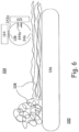
- Fig. 6 depicts a basic embodiment of the instrument 100, where a belt 126 draws the input material 108 past an integration sphere 242a, illumination source 120, and sensor 124, which operate in the manner as described elsewhere herein.
- the preparation module 102 and the control module 106 are not depicted in Fig. 6 , but the preparation module 102, the control module 106 and control lines are used in such an embodiment.
- control module 106 includes hardware to perform at least three functions, which are:
- the controller and signal processor 128, such as a personal computer or other computing device.
- the control functions include, but are not limited to, controlling the drafting operation between the two sets of fiber movements 112 and 118 in the preparation module 102, and controlling the movement of the web of input material 108 through the sensing instrument 104, such as with the fiber movements 126. It also processes the output of sensor 116, and provides feedback control to the drafting operation. Furthermore, it controls the spectral illumination source 120 and the input material fiber movement set 126, and processes the output of the sensors 122 and 124 via a measurement algorithm. The results of the measurement algorithm are communicated by the controller 128 to at least one of a human user interface 130 and a machine interface 132, which in some embodiments includes, but is not limited to, at least one of another type of textile machine.
- the measurement concept is based on the understanding that each different type of material that fibers can be made of, and which may be included in the input material 108, has unique spectral transmissive and reflective signatures, which are used for detecting, differentiating, and measuring the amounts of the different fiber materials in a blend of such in the web that is tested.
- two types of blend ratio measurements can be used:
- the instrument can be trained to determine k j .
- the following example describes a method to determine k f for a two-component blend, such as a blend of cotton-polyester fibers. This method can be expanded to multi-components blends as well.
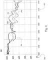
- Fig. 3 depicts a chart 300 for the relative spectral response 302 at different radiation wavelengths 304 (in nm) for natural cotton 306, polyester 308, and a 50-50 blend 310 by weight of cotton-polyester fibers.
- the first part is seeding, which includes collecting and maintaining the spectral signatures of all single components of interest throughout time for different fibers and materials. This can be achieved by either obtaining the spectral signatures from external sources (such as fiber manufacturers) or using the described instrument (during the training process) to create the spectral signatures of all single components of interest. These spectral signatures are maintained in a database, which can be connected to the controller 128 via the information database interface 134 as shown in Fig. 1 .
- the third part is matching criteria, which is a quantified measure of how close an unknown material is to the outcome of the searching process described in the previous step.
- Various mathematical goodness-of-fit measures such as a determination coefficient (R 2 ) or sum of squared errors (SSE), may be used to assess the match for every possible linear combination of components.
- R 2 determination coefficient
- SSE sum of squared errors
Landscapes
- Engineering & Computer Science (AREA)
- Textile Engineering (AREA)
- Chemical & Material Sciences (AREA)
- Health & Medical Sciences (AREA)
- Life Sciences & Earth Sciences (AREA)
- General Health & Medical Sciences (AREA)
- Analytical Chemistry (AREA)
- Biochemistry (AREA)
- Physics & Mathematics (AREA)
- General Physics & Mathematics (AREA)
- Immunology (AREA)
- Pathology (AREA)
- Food Science & Technology (AREA)
- Medicinal Chemistry (AREA)
- Materials Engineering (AREA)
- Mechanical Engineering (AREA)
- Investigating Or Analysing Materials By Optical Means (AREA)
- Treatment Of Fiber Materials (AREA)
Description
- This invention relates to the field of textile fiber characteristic measurement. More particularly, this invention relates to measurement of blended textile fiber characteristics. Even more particularly, it relates to a measurement instrument for identifying fiber blend composition and/or fiber blend ratio in an input material comprising fibers, and to a method for identifying fiber blend composition and/or fiber blend ratio in an input material comprising fibers.
- Textile fiber is the raw material for making textiles or textile intermediate products, such as yarn and fabric. Historically, cotton and other natural fibers have been the most important and utilized textile raw material. In recent years, however, synthetic or manmade fibers have gained popularity and utilization. As the name implies, synthetic fibers such as polyester and rayon are made artificially using chemical process.
- One of the most basic textile processes is converting fibers into yarn which is typically performed by spinning mills. A typical spinning mill may process only cotton fiber, only manmade fiber, or a blended combination of natural/manmade or manmade/manmade fibers (blends). Blends may offer a cost and performance advantage that might not be matched by cotton alone for a given application. In such case, the choice of fiber type and the ratio of different fiber types (blend ratio) in the blend plays an important role in cost and performance of the yarn produced.
- Therefore, material type and blend ratio are important parameters to maintain, monitor, and control in processing facilities such as a spinning mill. The current blend ratio measurement method is based on chemical techniques where a blend sample is initially weighed and then weighed again, sometimes iteratively so, after chemically removing each of the blend components one at a time (in those cases where more than one additional component is present). This is an offline and time-consuming method.
-
US-5,355,561 describes measuring a characteristic of a sliver to determine fiber blend. However, the fibers must be compressed at the location where they pass a commercially available measuring instrument. -
US-5,270,787 describes electro-optical measurement of individual entities in fibers that are delivered one at a time to a fluid stream. Each fiber is generally parallel with the direction of fluid flow. A sensor senses data such as the speed of the entity, length, fiber ribbon width, fineness, cross-sectional area, maturity, cross-sectional circularity, shape, surface roughness, etc. Optical filtering provides information about composition (natural or man-made) and appearance (color and polarization). However, additional, simpler, or other characteristics of fiber blend composition are desired. -
WO-93/13407 A1 - What is needed, therefore, is a measurement instrument and a method for identifying fiber blend composition and/or fiber blend ratio that address issues such as those described above, at least in part.
- The above and other needs are met by a measurement instrument and a method for identifying fiber blend composition and/or fiber blend ratio in an input material comprising fibers according to the independent claims. Advantageous embodiments are defined in the dependent claims.
- The measurement instrument according to the invention has a sample sensing module and a control module.
- The sample sensing module comprises a set of fiber movements for drawing the input material through the sample sensing module at a sensing speed. The sample sensing module further comprises an electromagnetic radiation source disposed on an adjacent side of the input material for directing a beam of electromagnetic radiation toward the input material at a sensing location within the sample sensing module, the beam of electromagnetic radiation containing at least two clearly distinct wavelengths of the electromagnetic spectrum. The sample sensing module further comprises a first electromagnetic radiation sensor disposed on an opposite side of the input material opposite the electromagnetic radiation source such that the first electromagnetic radiation sensor can receive transmitted portions of the beam of electromagnetic radiation that pass through the input material, and/or a second electromagnetic radiation sensor disposed on a same side of the input material as the electromagnetic radiation source such that the second electromagnetic radiation sensor can receive reflected portions of the beam of electromagnetic radiation that reflect off of the input material, wherein the second and/or the second electromagnetic radiation sensor are each configured to receive electromagnetic radiation at at least two clearly distinct wavelengths of the electromagnetic spectrum.
- The control module comprises a controller configured for receiving data signals from the first electromagnetic radiation sensor and/or the second electromagnetic radiation sensor, sending control signals to the electromagnetic radiation source and the set of fiber movements, and processing the data signals from the first electromagnetic radiation sensor and/or the second electromagnetic radiation sensor to determine the fiber blend composition and/or the fiber blend ratio in the input material.
- The measurement instrument according to the invention further comprises a sample preparation module for receiving and preparing the input material. The sample preparation module comprises a first preparatory set of fiber movements for receiving the input material and providing the input material at a preparatory speed that is less than or equal to the sensing speed The sample preparation module further comprises a second preparatory set of fiber movements for receiving the input material from the first preparatory set of fiber movements at the preparatory speed and providing the input material so received to the sample sensing module at the sensing speed, whereby a differential between the preparatory speed and the sensing speed is operable to dynamically adjust a density of the input material provided by the second preparatory set of fiber movements. The sample preparation module further comprises a preparatory electromagnetic radiation source disposed on a side adjacent the input material for directing a preparatory beam of electromagnetic radiation toward the input material at a preparatory location between the first preparatory set of fiber movements and the second preparatory set of fiber movements within the sample preparation module. The sample preparation module further comprises a preparatory electromagnetic radiation sensor disposed on an opposite side of the input material from the preparatory electromagnetic radiation source such that the preparatory electromagnetic radiation sensor can receive preparatory transmitted portions of the preparatory beam of electromagnetic radiation that pass through the input material. The controller of this embodiment is further configured for receiving data signals from the preparatory electromagnetic radiation sensor, sending control signals to the preparatory electromagnetic radiation source, the first preparatory set of fiber movements, and the second preparatory set of fiber movements, and processing the data signals from the preparatory electromagnetic radiation sensor and adjusting the control signals to the first preparatory set of fiber movements and the second preparatory set of fiber movements to provide a desired density of input material from the sample preparation module to the sample sensing module.
- In one embodiment, the measurement instrument further comprises a hopper in the sample preparation module for holding the input material prior to delivery of the input material to the first preparatory set of fiber movements.
- In one embodiment, the measurement instrument further comprises a source set of optics for delivering the beam of electromagnetic radiation to the input material.
- In one embodiment, the measurement instrument further comprises a first sensor set of optics for delivering the transmitted portion of the beam of electromagnetic radiation to the first electromagnetic radiation sensor, and/or further comprising a second sensor set of optics for delivering the reflected portion of the beam of electromagnetic radiation to the second electromagnetic radiation sensor.
- In one embodiment, the measurement instrument further comprises a machine interface in the control module configured for communicating the fiber blend composition and/or the fiber blend ratio to at least one of prior processing equipment and post processing equipment. The machine interface in the control module can be configured for communicating the fiber blend composition and/or the fiber blend ratio to a prior fiber blending machine.
- In one embodiment, the measurement instrument further comprises an information database in the control module for providing electromagnetic radiation transmission and reflectance data for a variety of fibers to the controller for use in determining fiber blend composition and/or fiber blend ratio. The electromagnetic radiation transmission and reflectance data can comprise data for manmade fibers and for natural fibers.
- In one embodiment, the spectral illumination source comprises one or more of LED, halogen lamp, mercury vapor lamp, incandescent lamp, deuterium lamp, and xenon lamp.
- In one embodiment, the first electromagnetic radiation sensor and/or the second electromagnetic radiation sensor comprise one or more of a spectrometer, photodiode, photodiode coupled with filter-wheel including band pass filters, photodiode array, each covered by narrow band filters, and hyper-spectral one-dimensional or two-dimensional imagers.
- In one embodiment, the first electromagnetic radiation sensor and/or the second electromagnetic radiation sensor comprises a plurality of electromagnetic radiation sensors disposed at differing positions along a surface of the input material in a direction perpendicular to the direction of movement of the input material.
- In one embodiment, the first electromagnetic radiation sensor and/or the second electromagnetic radiation sensor is movable along a surface of the input material in a direction perpendicular to the direction of movement of the input material.
- In one embodiment, the fiber movements comprise at least one roller and/or at least one belt.
- The method for identifying fiber blend composition and/or fiber blend ratio in an input material comprising fibers comprises the steps of:
- a.
- i. receiving the input material with a first preparatory set of fiber movements moving at a preparatory speed that is less than or equal to the sensing speed,
- ii. receiving the input material from the first preparatory set of fiber movements with a second preparatory set of fiber movements moving at the sensing speed, whereby a differential between the preparatory speed and the sensing speed is operable to dynamically adjust a density of the input material provided by the second preparatory set of fiber movements,
- iii. directing a preparatory beam of electromagnetic radiation toward the input material using a preparatory electromagnetic radiation source disposed on a side adjacent the input material and at a preparatory location between the first preparatory set of fiber movements and the second preparatory set of fiber movements, and
- iv. receiving preparatory transmitted portions of the preparatory beam of electromagnetic radiation that pass through the input material using a preparatory electromagnetic radiation sensor that is disposed on an opposite side of the input material from the preparatory electromagnetic radiation source,
- b. drawing the input material at a sensing speed using a set of fiber movements,
- c. directing a beam of electromagnetic radiation toward the input material at a sensing location using an electromagnetic radiation source disposed on an adjacent side of the input material, the beam of electromagnetic radiation containing at least two clearly distinct wavelengths of the electromagnetic spectrum,
- d. receiving transmitted portions of the beam of electromagnetic radiation that pass through the input material using a first electromagnetic radiation sensor disposed on an opposite side of the input material opposite the electromagnetic radiation source, and/or receiving reflected portions of the beam of electromagnetic radiation that reflect off of the input material using a second electromagnetic radiation sensor disposed on a same side of the input material as the electromagnetic radiation source, wherein the first electromagnetic radiation sensor and/or the second electromagnetic radiation sensor are each configured to receive electromagnetic radiation at at least two clearly distinct wavelengths of the electromagnetic spectrum,
- e. receiving data signals from the preparatory electromagnetic radiation sensor, and from the first electromagnetic radiation sensor and/or the second electromagnetic radiation sensor,
- f. sending control signals to the preparatory electromagnetic radiation source, the first preparatory set of fiber movements, the second preparatory set of fiber movements, the electromagnetic radiation source and the set of fiber movements,
- g. processing the data signals from the preparatory electromagnetic radiation sensor and adjusting the control signals to the first preparatory set of fiber movements and the second preparatory set of fiber movements to provide a desired density of input material to the sensing location, and
- h. processing the data signals from the first electromagnetic radiation sensor and/or the second electromagnetic radiation sensor to determine the fiber blend composition and/or the fiber blend ratio in the input material.
- In one embodiment, the method further comprises communicating the fiber blend composition and/or the fiber blend ratio to at least one of prior processing equipment and post processing equipment. The fiber blend composition and/or the fiber blend ratio can be communicated to a prior fiber blending machine.
- In one embodiment, the first electromagnetic radiation sensor and/or the second electromagnetic radiation sensor comprises a plurality of electromagnetic radiation sensors disposed at differing positions along a surface of the input material in a direction perpendicular to the direction of movement of the input material.
- In one embodiment, the method further comprises moving the first electromagnetic radiation sensor and/or the second electromagnetic radiation sensor along a surface of the input material in a direction perpendicular to the direction of movement of the input material.
- Further advantages of the invention are apparent by reference to the detailed description when considered in conjunction with the drawings, which are not to scale so as to more clearly show the details, wherein like reference numbers indicate like elements throughout the several views, and wherein:
-
Fig. 1 is a functional block diagram of a measurement instrument according to an embodiment of the present invention. -
Fig. 2 is a functional block diagram of a measurement instrument according to another embodiment of the present invention. -
Fig. 3 is a plot of a spectral response for cotton, polyester, and a 50-50 cotton/polyester blend according to an embodiment of the present invention. -
Fig. 4 is a functional block diagram of multiple sensors that are positioned within a mat of input material according to an embodiment of the present invention. -
Fig. 5 is a functional block diagram of a moving sensor that is positioned with a mat of input material according to another embodiment of the present invention. -
Fig. 6 is a functional block diagram of a measurement instrument using belts, according to another embodiment of the present invention. - With reference now to
Fig. 1 , there is depicted a functional block diagram of a blendratio measurement instrument 100 according to an embodiment of the present invention. Themeasurement instrument 100 as described herein can be used for either online or offline measurement. Themeasurement instrument 100 includes the following modules: -
Preparation module 102 -
Sensing module 104 -
Control module 106 -
Fig. 1 also depicts the main components of themeasurement instrument 100, including the following: -
Input material 108 for which blend composition and/or blend ratio is to be determined -
Input hopper 110 - Material preparation input fiber movement set 112
- Material
preparation illumination source 114 -
Material preparation sensor 116 - Material preparation output fiber movement set 118
-
Spectral illumination source 120 - Spectral
illumination transmission sensor 122 - Spectral
illumination reflection sensor 124 - Material sensing output fiber movement set 126
- Signal processor and
controller 128 -
Human user interface 130 -
Machine interface 132 -
Information database interface 134 - The
preparation module 102 brings thefibrous input material 108 into themeasurement instrument 100 and prepares theinput material 108 for presentation to thesensors input hopper 110 receives theinput material 108 in batch form and provides it to the first set of input fiber movements 112, and in other embodiments theinput material 108 is received by the first preparatory set of fiber movements 112 in a continuous feed, such as a sliver. Theinput material 108 can be received in various formats, such as bale, carding mat, sliver, and so forth. Thepreparation module 102 converts theinput material 108 to a web format, such as a sliver, if it is not already presented as such. - In some embodiments, there are two presentation forms for the
input material 108. One form is to present each fiber in theinput material 108 to thesensors input material 108 in the web format, which in some embodiments is of a consistent density, as described in more detail below. One way to achieve these various forms is by having variably-controlled drafting between the first preparatory set of fiber movements 112 and the second set of output fiber movements 118. By having the second preparatory set of fiber movements 118 rotating at a slightly faster speed than the first preparatory set of fiber movements 112, theinput material 108 can be stretched thinner, allowing for the presentation of a thinner web of fibers. At a certain speed differential, the fibers can be presented in an almost individualized form. Thus, the density or thickness of the web of theinput material 108 can be controlled in this manner. - The density of the
input material 108 is monitored by evaluating the transmission level of electromagnetic radiation from theelectromagnetic radiation source 114 through the web ofinput material 108 as received by theelectromagnetic radiation sensor 116. The spectral range of emitted and sensed electromagnetic radiation can include, but is not limited to, ultraviolet, visible, and infrared. - Examples of the
electromagnetic source 114 include, but are not limited to, one or more of LED, halogen lamp, mercury vapor lamp, incandescent lamp, deuterium lamp, and xenon lamp. Examples of theelectromagnetic sensor 116 include, but are not limited to, one or more of a spectrometer, photodiode, photodiode coupled with filter-wheel including band pass filters, photodiode array, each covered by narrow band filters, and hyper-spectral one-dimensional or two-dimensional imagers. - A closed-loop feedback control instrument in the
controller 128 uses the transmission level information from theelectromagnetic radiation sensor 116 to control the relative speed of the two sets of fiber movements 112 and 118, and thus the density of the web ofinput material 108. Thus, one important function of thepreparation module 102 is to control the density of the web ofinput material 108 that is delivered to thesensing module 104, as next described. - The
sensing module 104 senses different fiber types and the different amounts of different fiber types that are present in theinput material 108. This is accomplished by irradiating the web ofinput material 108 with electromagnetic radiation from thespectral illumination source 120, and then using at least one of aspectral transmission sensor 122 that detects the spectral transmission of theinput material 108 and aspectral reflection sensor 124 that detects the spectral reflection of theinput material 108. The spectral range of emitted and sensed electromagnetic radiation can include, but is not limited to, ultraviolet, visible, and infrared. - The
spectral illumination source 120 is configured to emit electromagnetic radiation that contains at least two clearly distinct wavelengths of the electromagnetic spectrum. It is preferably a broadbandelectromagnetic source 120. Examples of thespectral illumination source 120 include, but are not limited to, one or more of LED, halogen lamp, mercury vapor lamp, incandescent lamp, deuterium lamp, and xenon lamp. - The
electromagnetic sensors spectral illumination source 120, or can at least partly differ from them. Examples of theelectromagnetic sensors - In some embodiments, the illumination from the
source 120 is controlled by thecontroller 128 to be relatively uniform over the sensing area that is presented by the web of theinput material 108. In some embodiments, all of the radiation that attains either thesensor 124 or thesensor 122 is captured and sensed. In one embodiment this is accomplished with the use ofoptical elements 136 that receive and shape the radiation delivered by thesource 120, while other sets ofoptics sensors - Another embodiment uses an integrating sphere 242, as depicted in
Fig. 2 , which embeds theillumination source 120, thus providing a uniform illumination output. The integrating sphere is an optical component consisting of a hollow spherical cavity with its interior covered with a diffuse reflective coating that uniformly scatters the radiation. Electromagnetic radiation that is incident on any point on the inner surface is, by multiple scattering reflections, distributed equally to all other points on the sphere. The effects of the original direction of the electromagnetic radiation are thus reduced or even eliminated. - As depicted in
Fig. 2 , the integratingsphere 242a is used to both illuminate and receive the reflected illumination from theinput material 108. The radiation enters thesphere 242a from thesource 120, reflects around thesphere 242a, reflects from theinput material 108 through theport 246, is eventually collected by theoptics 138, and is then directly measured by thesensor 124. The baffle sets 244 prevent direct sensing of input radiation from thesource 120. - As indicated above, in one embodiment, some of the radiation from the
source 120 is transmitted through theinput material 108 and enters thesphere 242b. Again, baffle set 244b prevents direct reception of the illumination by thecollection optics 140. In this embodiment as depicted, the radiation received by theoptics 140 is passed to thesensor 122 via anoptical waveguide 248. In various embodiments, the same or different integrating spheres 242 can be used to capture reflected and transmitted signals, and optical waveguides can be used in either, none, or both of the integrating spheres 242. - In various embodiments, the sensing of the reflected or transmitted radiation is performed in either a static or dynamic mode, under the control of the
controller 128. In static mode, a desired portion of the web ofinput material 108 is brought into the field of view of at least one of thesensors input material 108 continues to move while at least one of thesensors input material 108. The movement of the web ofinput material 108 through thesensing module 104 is maintained in one embodiment by the set offiber movements 126. - In some embodiments the fiber movement sets 112, 118, and 126 are rotating rollers, where either one or both of the rollers are driven. In other words, in some embodiments, one of the rollers in each set could be passive. In other embodiments the fiber movement sets 112, 118, and 126 are sets of belts, where again, one belt could be driven and the other belt could be passive, or both belts could be driven. In yet another embodiment, each set includes a single driven belt and on the other side of the
input material 108 there is disposed a fixed or floating pressure plate. -
Fig. 6 depicts a basic embodiment of theinstrument 100, where abelt 126 draws theinput material 108 past anintegration sphere 242a,illumination source 120, andsensor 124, which operate in the manner as described elsewhere herein. Thepreparation module 102 and thecontrol module 106 are not depicted inFig. 6 , but thepreparation module 102, thecontrol module 106 and control lines are used in such an embodiment. - In some embodiments, the
control module 106 includes hardware to perform at least three functions, which are: - Process the gathered signals
- Control the hardware
- Interface with operators and other equipment
- This is accomplished by the controller and
signal processor 128, such as a personal computer or other computing device. The control functions include, but are not limited to, controlling the drafting operation between the two sets of fiber movements 112 and 118 in thepreparation module 102, and controlling the movement of the web ofinput material 108 through thesensing instrument 104, such as with thefiber movements 126. It also processes the output ofsensor 116, and provides feedback control to the drafting operation. Furthermore, it controls thespectral illumination source 120 and the input material fiber movement set 126, and processes the output of thesensors controller 128 to at least one of ahuman user interface 130 and amachine interface 132, which in some embodiments includes, but is not limited to, at least one of another type of textile machine. - The measurement concept is based on the understanding that each different type of material that fibers can be made of, and which may be included in the
input material 108, has unique spectral transmissive and reflective signatures, which are used for detecting, differentiating, and measuring the amounts of the different fiber materials in a blend of such in the web that is tested. - In one embodiment, two types of blend ratio measurements can be used:
- Blend.Ratioweight is the % of each unique fiber type in the blend by weight
- Blend.Ratiocount is the % of each unique fiber type in the blend by number of fibers
- For a given single unique fiber material (only one component fiber), the spectral signature of the fiber material can be presented as:

- Where:
- F(λi) is the spectral response of the fiber material for a single range or multiple ranges of wavelengths where λmin < λi < λmax, i = 1, 2, ..., n;
- R(λi) is the reflected or transmitting spectral response of the fiber material at wavelength λi , which is the only spectral response contributing to the spectral signature of the specific fiber material;
- S(λi) is the spectral response of the illumination source at wavelength λi ;
- P(λi) is the spectral response reduced along the optical path, such as by one or more of air, fiber optics, lens, window, mirror, filter, and grating, at wavelength λi ;
- D(λi) is spectral response of the sensor sensitivity at wavelength λi .
- Similarly, for a given blend of material with several component fibers, the spectral signature of the blend material can be the sum of spectral signatures of the components, presented as:

- Where:
- B(λi) is spectral response of the blend material for a single range or multiple ranges of wavelengths where λmin < λi < λmax, i = 1, 2, ..., n;
- m is the number of different component fiber types in the blend;
- kj is the percentage of each component fiber material type j in the blend;
- α is a constant due to the overall spectral response variation of light source, sensor, or sample presentation;
- Fj(λi) is the spectral response of the component fiber material type J in the blend, which expression is in the equation Math. 1.
- The instrument can be trained to determine kj . The following example describes a method to determine kf for a two-component blend, such as a blend of cotton-polyester fibers. This method can be expanded to multi-components blends as well.
Fig. 3 depicts achart 300 for the relativespectral response 302 at different radiation wavelengths 304 (in nm) fornatural cotton 306,polyester 308, and a 50-50blend 310 by weight of cotton-polyester fibers. A careful analysis of these spectra points to aspectral region 312 where equation Math. 2 may be solved for λmin = 1050 nm < λi < λmax =2500 nm to compute kj and thus Blend.Ratioweight or Blend.Ratiocount. - For a two-component blend, such as the polyester-cotton blend, equation Math. 2 can be expressed as:

- Where:


- To measure the blend ratio of a two-component blend in one embodiment, 1) a calibration algorithm, and 2) a measurement algorithm are used. One embodiment of a calibration algorithm is given below.
- 1. The intent of the calibration algorithm is to convert c1 and c2 to a known blend ratio Blend.Ratioweight or Blend.Ratiocount referred to as pw1 in following equations.
- 2. Train the instrument by collecting spectral response of at least three samples:
- a. 100 % component-1 (cotton in this case) referred to as F1measured(λi)
- b. 100 % component-2 (polyester in this case) referred to as F2measured(λi)
- c. Blend with known blend ratio pw1 (by weight or by fiber count) for component-1 and component-2 (cotton-polyester in this case) referred to as Bmeasured(λi)
- 3. Using a multiple regression method, compute Bpredicted(λi) using equation Math. 3, for λmin < λi < λmax, i = 1, 2, ..., n, to determine c1 and c2 to minimize

- 4. The internal blend ratio prior to calibration is defined as:


- 5. The calibration factor to convert internal blend ratio to Blend.Ratioweight or Blend.Ratiocount is computed as:

- Where:
- ps1 is the internal blend ratio per equation Math. 4;
- pw1 is the known calibration blend ratio in
Step 1; - SWC is a calibration factor for the two-component blend in blend ratio range of 0 % < ps1 < 100 %.
- Once SWC is determined via calibration, an unknown blend ratio of a given sample (assuming spectrally-similar component-1 and component-2 as used in calibration) can be computed as follows:
- 1. Capture the spectral response Bmeasured(λi) of the blend sample with unknown blend ratio;
- 2. Using a multiple regression method, compute Bpredicted(λi) using equation Math. 3, for λmin < λi < λmax, i = 1, 2, ..., n, to determine c1 and c2 to minimize

- 3. Compute the internal ps1 and ps2 per equations Math. 4 and Math. 5;
- 4. The unknown blend ratio is computed by:


- It is noted that the algorithm described above provides a blend ratio measurement for a single sensor field of view. The number of sensors, location of each sensor, and size of the sensor field of view depends on the width of the blend material, required blend ratio spatial resolution, required blend ratio uniformity spatial resolution, and cost considerations. For example,
Fig. 4 depicts an embodiment of ameasurement instrument 100 that containsinput material 108 moving along an X direction through multiple fields of view of stationary multiple sensors 450a, 450b, and 450c. The multiple sensors 450a, 450b, and 450c are disposed at differing positions along a surface of theinput material 108 in a Y direction, which is perpendicular to the X direction, so as to cover at least part of and preferably the whole width of theinput material 108. - Alternately,
Fig. 5 shows yet another embodiment of ameasurement instrument 100 that containsinput material 108 moving along an X direction through one field of view of a single sensor 450d, which in some embodiments is a movable sensor 450d. Simultaneously, theinput material 108 can also be sensed along the Y direction by either moving the sensor 450d or moving theinput material 108 in the Y direction along a surface of theinput material 108. The movement in the Y direction is such that at least part of and preferably the whole width of theinput material 108 is covered. In both embodiments, the result is an array of position-dependent blend ratio measurements that relates to different portions of theinput material 108. Thus, the position-stamped blend ratio can be presented as:
- Where:
- k is the index of the kth component, k = 1, 2, ..., l;
- i is the position index of X direction, i = 1, 2, ..., m;
- j is the position index of Y direction, j = 1, 2, ..., n.
- For the embodiment of
Fig. 4 , n = 3 if three sensors 450a, 450b, and 450c are present. For the embodiment ofFig. 5 , the data can be either one-dimensional or two-dimensional, that is n = 1 or n > 1. - Based on the testing data pk(i,j) in equation Math. 9, further statistical analysis can be done to reveal spatial distribution of blend ratio along X direction and Y direction. Thus, using the testing data pk(i,j) in equation Math 9, the further calculations and position values can be presented as:
Y1 Y2 ... Yn Avg_Y SD_Y X1 pk(1,1) pk(1,2) ... pk(1,n) pyk(1) dpyk(1) X2 pk(2,1) pk(2,2) ... pk(2,n) pyk(2) dpyk(2) : : : : : : Xm pk(m,1) pk(m,2) ... pk(m,n) pyk(m) dpyk(m) Avg_X pxk(1) pxk(2) ... pxk(n) pxyk SD_X dpxk(1) dpxk(2) ... dpxk(n) dpxyk - Where:
- k is the index of the kth component, k = 1, 2, ..., l;
- pxk(j), j = 1, 2, ..., n, is the average of test points along X direction with Y direction index ofj;
- dpxk(j), j = 1, 2, ..., n, is the standard deviation of test points along X direction with Y direction index ofj;
- pyk(i), i = 1, 2, ..., m, is the average of test points along Y direction with X direction index of i;
- dpyk(i), i = 1, 2, ..., m, is the standard deviation of test points along Y direction with X direction index of i;
- pxyk is the average of all test points of the sample;
- dpxyk is the standard deviation of all test points of the sample.
- pxyk reveals the overall blend ratio of the sample, and dpxyk reveals the overall blend ratio variation (uniformity) of the sample. pxk(j), j = 1, 2, ..., n, reveals the blend ratio distribution along the Y direction, but dpxk(j), j = 1, 2, ..., n, reveals the blend ratio variation (uniformity) along the X direction. Similarly, pyk(i), i = 1, 2, ..., m, reveals the blend ratio distribution along the X direction, but dpyk(i), i = 1, 2, ..., m, reveals the blend ratio variation (uniformity) along the Y direction.
- Plots of pk(i,j), pxk(j) and pyk(i), where i = 1, 2, ..., m and j = 1, 2, ..., n, graphically reveal the blend ratio distribution characters of the sample. For example, drawing a sliver of blended fibers usually has a stripe structure, so that the blend ratio varies in a certain period across the sliver (Y direction). The size of the blend ratio period across the sliver and blend variation levels along and across the sliver are valuable information for spinning process quality control.
- The
measurement instrument 100 can determine the blend ratio, assuming the main components of the blends are known in advance. Yet another capability of themeasurement instrument 100 is to predict the material type of an unknown single-component fiber and multi-component blend. A spectral signature of an unknown material can be compared to a single component or component combinations in a database, and the closest match can be found. - The component identification algorithm for an unknown material includes three major parts described in the following.
- The first part is seeding, which includes collecting and maintaining the spectral signatures of all single components of interest throughout time for different fibers and materials. This can be achieved by either obtaining the spectral signatures from external sources (such as fiber manufacturers) or using the described instrument (during the training process) to create the spectral signatures of all single components of interest. These spectral signatures are maintained in a database, which can be connected to the
controller 128 via theinformation database interface 134 as shown inFig. 1 . - The second part is searching, which includes searching for a match between the spectral signature of the unknown material and every possible single-component/multi-component blend using the linear combination expression in equation Math 2, which can also be expressed as:

- Where:

- m = 1, single-component;
- m = 2, 3, ..., M, multi-component blend, where M is the number of components in the calibration file.
- Take, for example, the case where there are only four components (M = 4) of interest, such as cotton, polyester, acrylic, and viscose. In this case, the total number of possible combinations is 15, which can be indexed as (1), (2), (3), (4), (1, 2), (1, 3), (1, 4), (2, 3), (2, 4), (3, 4), (1,2,3), (1,2,4), (1,3,4), (2,3,4), (1,2,3,4).
- The third part is matching criteria, which is a quantified measure of how close an unknown material is to the outcome of the searching process described in the previous step. Various mathematical goodness-of-fit measures, such as a determination coefficient (R2) or sum of squared errors (SSE), may be used to assess the match for every possible linear combination of components. In the case where no component combination has a goodness-of-fit calculation within the criterial ranges, the unknown material may have a component that is not included in the database of known materials (first part); otherwise, the best fit should reveal the component combinations for the unknown material.
- The methods described above can be implemented in the controller/
signal processor 128, as depicted inFigs. 1 and2 . However, the implementation does not depend on a specific embodiment of the blendratio measurement instrument 100 according to the invention. - The foregoing description of embodiments for this invention has been presented for purposes of illustration and description. It is not intended to be exhaustive or to limit the invention to the precise form disclosed. Obvious modifications or variations are possible in light of the above teachings. The embodiments are chosen and described in an effort to provide illustrations of the principles of the invention and its practical application, and to thereby enable one of ordinary skill in the art to utilize the invention in various embodiments and with various modifications as are suited to the particular use contemplated. All such modifications and variations are within the scope of the invention as determined by the appended claims.
Claims (13)
- A measurement instrument (100) for identifying fiber blend composition and/or fiber blend ratio in an input material (108) comprising fibers, the measurement instrument (100) comprising:a. a sample sensing module (104) comprising:i. an electromagnetic radiation source (120) disposed on an adjacent side of the input material (108) for directing a beam of electromagnetic radiation toward the input material (108) at a sensing location within the sample sensing module (104), the beam of electromagnetic radiation containing at least two clearly distinct wavelengths of the electromagnetic spectrum, andii. a first electromagnetic radiation sensor (122) disposed on an opposite side of the input material (108) opposite the electromagnetic radiation source (120) such that the first electromagnetic radiation sensor (122) can receive transmitted portions of the beam of electromagnetic radiation that pass through the input material (108), and/or a second electromagnetic radiation sensor (124) disposed on a same side of the input material (108) as the electromagnetic radiation source (120) such that the second electromagnetic radiation sensor (124) can receive reflected portions of the beam of electromagnetic radiation that reflect off of the input material (108), wherein the first electromagnetic radiation sensor (122) and/or the second electromagnetic radiation sensor (124) are each configured to receive electromagnetic radiation at at least two clearly distinct wavelengths of the electromagnetic spectrum, andb. a control module (106) comprising a controller (128) configured for:i. receiving data signals from the first electromagnetic radiation sensor (122) and/or the second electromagnetic radiation sensor (124),ii. sending control signals to the electromagnetic radiation source (120), andiii. processing the data signals from the first electromagnetic radiation sensor (122) and/or the second electromagnetic radiation sensor (124) to determine the fiber blend composition and/or the fiber blend ratio in the input material (108),characterized in thatc. the sample sensing module (104) further comprising a set of fiber movements (126a, 126b) for drawing the input material (108) through the sample sensing module (104) at a sensing speed,d. the measurement instrument (100) further comprising a sample preparation module (102) for receiving and preparing the input material (108), the sample preparation module (102) comprising:i. a first preparatory set of fiber movements (112a, 112b) for receiving the input material (108) and providing the input material (108) at a preparatory speed that is less than or equal to the sensing speed,ii. a second preparatory set of fiber movements (118a, 118b) for receiving the input material (108) from the first preparatory set of fiber movements (112a, 112b) at the preparatory speed and providing the input material (108) so received to the sample sensing module (104) at the sensing speed, whereby a differential between the preparatory speed and the sensing speed is operable to dynamically adjust a density of the input material (108) provided by the second preparatory set of fiber movements (118a, 118b),iii. a preparatory electromagnetic radiation source (114) disposed on a side adjacent the input material (108) for directing a preparatory beam of electromagnetic radiation toward the input material (108) at a preparatory location between the first preparatory set of fiber movements (112a, 112b) and the second preparatory set of fiber movements (118a, 118b) within the sample preparation module (102), andiv. a preparatory electromagnetic radiation sensor (116) disposed on an opposite side of the input material (108) from the preparatory electromagnetic radiation source (114) such that the preparatory electromagnetic radiation sensor (116) can receive preparatory transmitted portions of the preparatory beam of electromagnetic radiation that pass through the input material (108), ande. the controller (128) further configured for:i. receiving data signals from the preparatory electromagnetic radiation sensor (116),ii. sending control signals to the preparatory electromagnetic radiation source (114), the first preparatory set of fiber movements (112a, 112b), and the second preparatory set of fiber movements (118a, 118b),iii. sending control signals to the set of fiber movements (126a, 126b), andiv. processing the data signals from the preparatory electromagnetic radiation sensor (116) and adjusting the control signals to the first preparatory set of fiber movements (112a, 112b) and the second preparatory set of fiber movements (118a, 118b) to provide a desired density of input material from the sample preparation module (102) to the sample sensing module (104).
- The measurement instrument (100) of claim 1, further comprising a hopper (110) in the sample preparation module (102) for holding the input material (108) prior to delivery of the input material (108) to the first preparatory set of fiber movements (112a, 112b).
- The measurement instrument (100) of any of the preceding claims, further comprising:a source set of optics (136) for delivering the beam of electromagnetic radiation to the input material (108), and/ora first sensor set of optics (140) for delivering the transmitted portion of the beam of electromagnetic radiation to the first electromagnetic radiation sensor (122), and/ora second sensor set of optics (138) for delivering the reflected portion of the beam of electromagnetic radiation to the second electromagnetic radiation sensor (124).
- The measurement instrument (100) of any of the preceding claims, further comprising a machine interface (132) in the control module (106) configured for communicating the fiber blend composition and/or the fiber blend ratio to at least one of prior processing equipment and post processing equipment.
- The measurement instrument (100) of any of the preceding claims, further comprising an information database interface (134) in the control module (106) for providing electromagnetic radiation transmission and reflectance data for a variety of fibers to the controller (128) for use in determining fiber blend composition and/or fiber blend ratio.
- The measurement instrument (100) of claim 5, wherein the electromagnetic radiation transmission and reflectance data comprise data for manmade fibers and for natural fibers.
- The measurement instrument (100) of any of the preceding claims, wherein the spectral illumination source (120) comprises one or more of LED, halogen lamp, mercury vapor lamp, incandescent lamp, deuterium lamp, and xenon lamp.
- The measurement instrument (100) of any of the preceding claims, wherein the first electromagnetic radiation sensor (122) and/or the second electromagnetic radiation sensor (124) comprise one or more of a spectrometer, photodiode, photodiode coupled with filter-wheel including band pass filters, photodiode array, each covered by narrow band filters, and hyper-spectral one-dimensional or two-dimensional imagers.
- The measurement instrument (100) of any of the preceding claims, wherein the first electromagnetic radiation sensor (122) and/or the second electromagnetic radiation sensor (124) comprises a plurality of electromagnetic radiation sensors (450a, 450b, 450c) disposed along a surface of the input material at differing positions in a direction (Y) perpendicular to the direction of movement (X) of the input material (108).
- The measurement instrument (100) of any of the preceding claims, wherein the first electromagnetic radiation sensor (122, 450d) and/or the second electromagnetic radiation sensor (124, 450d) is movable along a surface of the input material (108) in a direction (Y) perpendicular to the direction of movement (X) of the input material (108).
- The measurement instrument (100) of any of the preceding claims, wherein the fiber movements (112a, 112b; 118a, 118b; 126a, 126b; 126) comprise at least one roller (112a, 112b; 118a, 118b; 126a, 126b) and/or at least one belt (126).
- A method for identifying fiber blend composition and/or fiber blend ratio in an input material (108) comprising fibers, the method comprising the steps of:a.i. receiving the input material (108) with a first preparatory set of fiber movements (112a, 112b) moving at a preparatory speed that is less than or equal to the sensing speed,ii. receiving the input material (108) from the first preparatory set of fiber movements (112a, 112b) with a second preparatory set of fiber movements (118a, 118b) moving at the sensing speed, whereby a differential between the preparatory speed and the sensing speed is operable to dynamically adjust a density of the input material (108) provided by the second preparatory set of fiber movements (118a, 118b),iii. directing a preparatory beam of electromagnetic radiation toward the input material (108) using a preparatory electromagnetic radiation source (114) disposed on a side adjacent the input material (108) and at a preparatory location between the first preparatory set of fiber movements (112a, 112b) and the second preparatory set of fiber movements (118a, 118b), andiv. receiving preparatory transmitted portions of the preparatory beam of electromagnetic radiation that pass through the input material (108) using a preparatory electromagnetic radiation sensor (116) that is disposed on an opposite side of the input material (108) from the preparatory electromagnetic radiation source (114),b. drawing the input material (108) at a sensing speed using a set of fiber movements (126a, 126b),c. directing a beam of electromagnetic radiation toward the input material (108) at a sensing location using an electromagnetic radiation source (120) disposed on an adjacent side of the input material (108), the beam of electromagnetic radiation containing at least two clearly distinct wavelengths of the electromagnetic spectrum,d. receiving transmitted portions of the beam of electromagnetic radiation that pass through the input material (108) using a first electromagnetic radiation sensor (122) disposed on an opposite side of the input material (108) opposite the electromagnetic radiation source (120), and/or receiving reflected portions of the beam of electromagnetic radiation that reflect off of the input material (108) using a second electromagnetic radiation sensor (124) disposed on a same side of the input material (108) as the electromagnetic radiation source (120), wherein the first electromagnetic radiation sensor (122) and/or the second electromagnetic radiation sensor (124) are each configured to receive electromagnetic radiation at at least two clearly distinct wavelengths of the electromagnetic spectrum,e. receiving data signals from the preparatory electromagnetic radiation sensor (116), and from the first electromagnetic radiation sensor (122) and/or the second electromagnetic radiation sensor (124),f. sending control signals to the preparatory electromagnetic radiation source (114), the first preparatory set of fiber movements (112a, 112b), the second preparatory set of fiber movements (118a, 118b), the electromagnetic radiation source (120) and the set of fiber movements (126a, 126b),g. processing the data signals from the preparatory electromagnetic radiation sensor (116) and adjusting the control signals to the first preparatory set of fiber movements (112a, 112b) and the second preparatory set of fiber movements (118a, 118b) to provide a desired density of input material (108) to the sensing location, andh. processing the data signals from the first electromagnetic radiation sensor (122) and/or the second electromagnetic radiation sensor (124) to determine the fiber blend composition and/or the fiber blend ratio in the input material (108).
- The method of claim 12, further comprising communicating the fiber blend composition and/or the fiber blend ratio to at least one of prior processing equipment and post processing equipment.
Applications Claiming Priority (2)
| Application Number | Priority Date | Filing Date | Title |
|---|---|---|---|
| US201762558506P | 2017-09-14 | 2017-09-14 | |
| PCT/CH2018/000038 WO2019051620A1 (en) | 2017-09-14 | 2018-09-11 | Fiber blend identification and/or ratio measurement |
Publications (2)
| Publication Number | Publication Date |
|---|---|
| EP3662283A1 EP3662283A1 (en) | 2020-06-10 |
| EP3662283B1 true EP3662283B1 (en) | 2025-07-02 |
Family
ID=63832158
Family Applications (1)
| Application Number | Title | Priority Date | Filing Date |
|---|---|---|---|
| EP18785247.0A Active EP3662283B1 (en) | 2017-09-14 | 2018-09-11 | Fiber blend identification and/or ratio measurement |
Country Status (4)
| Country | Link |
|---|---|
| US (1) | US11402335B2 (en) |
| EP (1) | EP3662283B1 (en) |
| CN (1) | CN111133310B (en) |
| WO (1) | WO2019051620A1 (en) |
Families Citing this family (7)
| Publication number | Priority date | Publication date | Assignee | Title |
|---|---|---|---|---|
| CN117242332A (en) * | 2021-03-26 | 2023-12-15 | 乌斯特技术股份公司 | Detection of the mixing ratio of two components in textile fiber structures |
| EP4419907A4 (en) * | 2021-10-18 | 2025-08-27 | Refiberd Inc | INTELLIGENT DETECTION OF THE FIBER COMPOSITION OF TEXTILES THROUGH AUTOMATED ANALYSIS USING MACHINE LEARNING MODELS |
| WO2024031201A1 (en) * | 2022-08-08 | 2024-02-15 | Uster Technologies Ag | Investigating a textile fibre structure containing two components |
| US12029537B2 (en) * | 2022-08-23 | 2024-07-09 | Samsung Electronics Co., Ltd | Polarized photoplethysmography (PPG) biosensors, arrays and systems |
| CH720833A1 (en) * | 2023-06-06 | 2024-12-13 | Rieter Ag Maschf | Method for controlling and adjusting the fiber mixture of a fiber preparation machine |
| LU505551B1 (en) * | 2023-11-16 | 2025-05-19 | Saurer Intelligent Technology AG | Illumination receiving system and method for measuring |
| LU505549B1 (en) * | 2023-11-16 | 2025-05-19 | Saurer Intelligent Technology AG | Illumination projector, method of manufacturing and method of projection |
Family Cites Families (34)
| Publication number | Priority date | Publication date | Assignee | Title |
|---|---|---|---|---|
| BE704412A (en) * | 1967-09-28 | 1968-02-01 | ||
| GB2095828B (en) * | 1981-03-31 | 1985-12-18 | Wool Dev Int | Detection of defects in fibrous arrays |
| US5270787A (en) | 1990-03-14 | 1993-12-14 | Zellweger Uster Inc. | Electro-optical methods and apparatus for high speed, multivariate measurement of individual entities in fiber or other samples |
| US5321496A (en) | 1990-03-14 | 1994-06-14 | Zellweger Uster, Inc. | Apparatus for monitoring trash in a fiber sample |
| DE59108679D1 (en) * | 1990-11-02 | 1997-05-28 | Rieter Ag Maschf | Method for determining a property of a fiber structure |
| EP0602145B1 (en) | 1991-09-06 | 1999-03-03 | Commonwealth Scientific And Industrial Research Organisation | Measurement method and apparatus |
| DE4131664A1 (en) * | 1991-09-23 | 1993-03-25 | Rieter Ingolstadt Spinnerei | METHOD AND DEVICE FOR DETECTING YARN ERRORS |
| CH683293A5 (en) * | 1991-12-20 | 1994-02-15 | Peyer Ag Siegfried | Foreign fiber detection in yarns. |
| CH683035A5 (en) * | 1992-01-31 | 1993-12-31 | Loepfe Ag Geb | Method and apparatus for detection of impurities, in particular foreign fibers, in elongate textile structures. |
| CH683378A5 (en) * | 1992-03-17 | 1994-02-28 | Zellweger Uster Ag | Method and apparatus for detecting impurities in a textile test material and using the apparatus. |
| US5311290A (en) | 1992-09-30 | 1994-05-10 | Pulp And Paper Research Institute Of Canada | Imaging apparatus and method of fiber analysis |
| US5367747A (en) | 1992-12-31 | 1994-11-29 | Zellweger Uster, Inc. | Needle-based apparatus for individualizing fibers and other textile entities for testing purposes |
| DE69324557T2 (en) * | 1992-12-31 | 1999-09-23 | Zellweger Uster, Inc. | Continuous two-dimensional monitoring of thin tissue of textile material |
| JPH07120375A (en) | 1993-10-21 | 1995-05-12 | Hitachi Ltd | Flow type particle image analysis method and apparatus |
| EP0652432A1 (en) | 1993-11-04 | 1995-05-10 | BARCO nv/Automation | Device for detecting foreign material, especially foreign fibres in textile articles in motion |
| AUPM533094A0 (en) | 1994-04-27 | 1994-05-19 | Commonwealth Scientific And Industrial Research Organisation | Methods and apparatus for determining a first parameter(s) of an object |
| US5786894A (en) | 1996-10-25 | 1998-07-28 | International Paper Company | Measurement of paper pulp and fiber visual characteristics |
| AU2828699A (en) | 1998-01-22 | 1999-08-09 | Maschinenfabrik Rieter A.G. | Method and device for measuring fibre length |
| US5991046A (en) * | 1998-07-14 | 1999-11-23 | Valmet Automation Inc. | Method and apparatus for optically measuring properties of a moving web |
| US6040905A (en) | 1998-08-05 | 2000-03-21 | Zellweger Uster, Inc. | Fiber color grading system |
| DE19939711B4 (en) * | 1999-08-21 | 2015-03-12 | Saurer Germany Gmbh & Co. Kg | Method and device for detecting foreign bodies in a longitudinally moved thread |
| DE10009131A1 (en) * | 2000-02-26 | 2001-08-30 | Schlafhorst & Co W | Method and device for the optical detection of impurities, in particular foreign fibers, in longitudinally moving yarn |
| JP4811813B2 (en) * | 2000-05-31 | 2011-11-09 | ウステル・テヒノロジーズ・アクチエンゲゼルシヤフト | Method and apparatus for confirming contaminants in filamentary product moved in the longitudinal direction |
| WO2002035308A2 (en) * | 2000-10-23 | 2002-05-02 | Am Vision Technologies Ltd. | Method and device for optically determining bulk density and uniformity of web configured material during in-line processing |
| JP2004535582A (en) * | 2001-07-12 | 2004-11-25 | ウステル・テヒノロジーズ・アクチエンゲゼルシヤフト | Method and apparatus for identifying contaminants in fiber material |
| US7307729B2 (en) * | 2002-08-19 | 2007-12-11 | Green Vision Systems Ltd. | Electro-optically inspecting and determining internal properties and characteristics of a longitudinally moving rod of material |
| AU2003222403A1 (en) | 2003-03-28 | 2004-10-18 | Premier Polytronics, Pvt. Ltd. | Automatic fiber processing system including method and apparatus for producing end-aligned fiber samples |
| DE102004030967A1 (en) | 2004-06-26 | 2006-01-12 | Trützschler GmbH & Co KG | Apparatus for measuring the mass of a fiber material passing through a spinning preparation machine or plant |
| US7880156B2 (en) * | 2006-12-27 | 2011-02-01 | Honeywell International Inc. | System and method for z-structure measurements using simultaneous multi-band tomography |
| CN101246121B (en) * | 2008-03-21 | 2010-09-08 | 东华大学 | A Yarn Composition Detection Method Based on Polarized Light Microscope |
| CH699219A1 (en) * | 2008-07-25 | 2010-01-29 | Uster Technologies Ag | Method and device for yarn cleaning. |
| EP2730914B1 (en) * | 2011-10-28 | 2016-07-13 | Toray Industries, Inc. | Prepreg production method |
| FR3005042B1 (en) * | 2013-04-26 | 2016-01-01 | Snecma | WEAVING OR WINDING MACHINE FOR FIBROUS TEXTURE FOR ANOMALY CONTROL BY IMAGE ANALYSIS |
| CN104865218B (en) * | 2015-05-06 | 2017-06-23 | 江西出入境检验检疫局检验检疫综合技术中心 | The quick method for determining cotton ramie blended spinning fiber content |
-
2018
- 2018-09-11 US US16/644,845 patent/US11402335B2/en active Active
- 2018-09-11 CN CN201880057493.9A patent/CN111133310B/en active Active
- 2018-09-11 WO PCT/CH2018/000038 patent/WO2019051620A1/en not_active Ceased
- 2018-09-11 EP EP18785247.0A patent/EP3662283B1/en active Active
Also Published As
| Publication number | Publication date |
|---|---|
| CN111133310B (en) | 2023-01-24 |
| US11402335B2 (en) | 2022-08-02 |
| WO2019051620A1 (en) | 2019-03-21 |
| EP3662283A1 (en) | 2020-06-10 |
| CN111133310A (en) | 2020-05-08 |
| US20210199593A1 (en) | 2021-07-01 |
Similar Documents
| Publication | Publication Date | Title |
|---|---|---|
| EP3662283B1 (en) | Fiber blend identification and/or ratio measurement | |
| EP0758083B1 (en) | Device for spectral remission and transmission measurement | |
| CN101784883B (en) | Electromagnetic detection method and apparatus for the manufacture of fiber webs | |
| US20030038938A1 (en) | Apparatus and method for measuring optical characteristics of an object or material | |
| US20020001078A1 (en) | Optical measuring arrangement, in particular for quality control in continuous processes | |
| EP1242811B1 (en) | Method and apparatus for controlling the manufacturing quality of a moving web | |
| WO2005038443A1 (en) | Different-kind-of-object detector employing plane spectrometer | |
| CN106959307A (en) | Measure the measuring method and device of textile fabric water content, length and dynamometry feature | |
| EP1624302A2 (en) | Measuring and testing continuous elongated textile material | |
| JP2013044729A (en) | Coating state measuring method | |
| EP2475978A1 (en) | Device and method for optically scanning a moving textile material | |
| EP1907830B1 (en) | Detecting foreign substances in a textile material | |
| ITTO950796A1 (en) | PROCEDURE AND SYSTEM FOR DETECTING CHEMICAL-PHYSICAL PARAMETERS. | |
| Montalvo Jr et al. | Analysis of cotton | |
| US20240175806A1 (en) | Detecting a Mixture Ratio of Two Components of a Textile Fiber Structure | |
| DE102017108552A1 (en) | Spectrometric measuring head with several transmission light entry windows | |
| ITMI20001954A1 (en) | DEVICE OF A CARDING MACHINE OR CARDING MACHINE, IN WHICH A FIBER HAIR FROM TEXTILE FIBERS IS FORMED, FOR EXAMPLE COTTON, CHEMICAL FIBERS AND SIM | |
| KR20010101831A (en) | Process for determining the dye uptake of polyethylene terephthalate fibres | |
| Ghosh | On-line measurement of polyvinyl alcohol size on warp yarns using a near-IR diffuse reflectance spectroscopy method | |
| DE29512646U1 (en) | Device for spectral color value measurement | |
| CN113970522B (en) | A method for online analysis of composite products in a machine for producing absorbent hygiene products | |
| JP2005321349A (en) | Material judgment device | |
| EP4314769B1 (en) | Optical device | |
| EP1247078A4 (en) | APPARATUS AND METHOD FOR MEASURING THE OPTICAL CHARACTERISTICS OF AN OBJECT OR MATERIAL | |
| WO2011086380A2 (en) | Spectrometric characterization of heterogeneity |
Legal Events
| Date | Code | Title | Description |
|---|---|---|---|
| STAA | Information on the status of an ep patent application or granted ep patent |
Free format text: STATUS: UNKNOWN |
|
| STAA | Information on the status of an ep patent application or granted ep patent |
Free format text: STATUS: THE INTERNATIONAL PUBLICATION HAS BEEN MADE |
|
| PUAI | Public reference made under article 153(3) epc to a published international application that has entered the european phase |
Free format text: ORIGINAL CODE: 0009012 |
|
| STAA | Information on the status of an ep patent application or granted ep patent |
Free format text: STATUS: REQUEST FOR EXAMINATION WAS MADE |
|
| 17P | Request for examination filed |
Effective date: 20200128 |
|
| AK | Designated contracting states |
Kind code of ref document: A1 Designated state(s): AL AT BE BG CH CY CZ DE DK EE ES FI FR GB GR HR HU IE IS IT LI LT LU LV MC MK MT NL NO PL PT RO RS SE SI SK SM TR |
|
| AX | Request for extension of the european patent |
Extension state: BA ME |
|
| DAV | Request for validation of the european patent (deleted) | ||
| DAX | Request for extension of the european patent (deleted) | ||
| STAA | Information on the status of an ep patent application or granted ep patent |
Free format text: STATUS: EXAMINATION IS IN PROGRESS |
|
| 17Q | First examination report despatched |
Effective date: 20220804 |
|
| REG | Reference to a national code |
Ref country code: DE Ref legal event code: R079 Free format text: PREVIOUS MAIN CLASS: G01N0033360000 Ipc: D01G0031000000 Ref document number: 602018083216 Country of ref document: DE |
|
| RIC1 | Information provided on ipc code assigned before grant |
Ipc: G01N 21/89 20060101ALI20230822BHEP Ipc: D06H 3/00 20060101ALI20230822BHEP Ipc: G01N 33/36 20060101ALI20230822BHEP Ipc: D01H 13/32 20060101ALI20230822BHEP Ipc: D01G 31/00 20060101AFI20230822BHEP |
|
| GRAP | Despatch of communication of intention to grant a patent |
Free format text: ORIGINAL CODE: EPIDOSNIGR1 |
|
| STAA | Information on the status of an ep patent application or granted ep patent |
Free format text: STATUS: GRANT OF PATENT IS INTENDED |
|
| INTG | Intention to grant announced |
Effective date: 20241206 |
|
| GRAJ | Information related to disapproval of communication of intention to grant by the applicant or resumption of examination proceedings by the epo deleted |
Free format text: ORIGINAL CODE: EPIDOSDIGR1 |
|
| STAA | Information on the status of an ep patent application or granted ep patent |
Free format text: STATUS: EXAMINATION IS IN PROGRESS |
|
| INTC | Intention to grant announced (deleted) | ||
| GRAP | Despatch of communication of intention to grant a patent |
Free format text: ORIGINAL CODE: EPIDOSNIGR1 |
|
| STAA | Information on the status of an ep patent application or granted ep patent |
Free format text: STATUS: GRANT OF PATENT IS INTENDED |
|
| INTG | Intention to grant announced |
Effective date: 20250331 |
|
| GRAS | Grant fee paid |
Free format text: ORIGINAL CODE: EPIDOSNIGR3 |
|
| GRAA | (expected) grant |
Free format text: ORIGINAL CODE: 0009210 |
|
| STAA | Information on the status of an ep patent application or granted ep patent |
Free format text: STATUS: THE PATENT HAS BEEN GRANTED |
|
| AK | Designated contracting states |
Kind code of ref document: B1 Designated state(s): AL AT BE BG CH CY CZ DE DK EE ES FI FR GB GR HR HU IE IS IT LI LT LU LV MC MK MT NL NO PL PT RO RS SE SI SK SM TR |
|
| REG | Reference to a national code |
Ref country code: GB Ref legal event code: FG4D |
|
| REG | Reference to a national code |
Ref country code: CH Ref legal event code: EP |
|
| REG | Reference to a national code |
Ref country code: DE Ref legal event code: R096 Ref document number: 602018083216 Country of ref document: DE |
|
| REG | Reference to a national code |
Ref country code: IE Ref legal event code: FG4D |
|
| REG | Reference to a national code |
Ref country code: CH Ref legal event code: U11 Free format text: ST27 STATUS EVENT CODE: U-0-0-U10-U11 (AS PROVIDED BY THE NATIONAL OFFICE) Effective date: 20251015 |
|
| REG | Reference to a national code |
Ref country code: NL Ref legal event code: MP Effective date: 20250702 |
|
| PG25 | Lapsed in a contracting state [announced via postgrant information from national office to epo] |
Ref country code: PT Free format text: LAPSE BECAUSE OF FAILURE TO SUBMIT A TRANSLATION OF THE DESCRIPTION OR TO PAY THE FEE WITHIN THE PRESCRIBED TIME-LIMIT Effective date: 20251103 |
|
| PG25 | Lapsed in a contracting state [announced via postgrant information from national office to epo] |
Ref country code: NL Free format text: LAPSE BECAUSE OF FAILURE TO SUBMIT A TRANSLATION OF THE DESCRIPTION OR TO PAY THE FEE WITHIN THE PRESCRIBED TIME-LIMIT Effective date: 20250702 |
|
| REG | Reference to a national code |
Ref country code: AT Ref legal event code: MK05 Ref document number: 1809347 Country of ref document: AT Kind code of ref document: T Effective date: 20250702 |
|
| PG25 | Lapsed in a contracting state [announced via postgrant information from national office to epo] |
Ref country code: IS Free format text: LAPSE BECAUSE OF FAILURE TO SUBMIT A TRANSLATION OF THE DESCRIPTION OR TO PAY THE FEE WITHIN THE PRESCRIBED TIME-LIMIT Effective date: 20251102 |
|
| PGFP | Annual fee paid to national office [announced via postgrant information from national office to epo] |
Ref country code: DE Payment date: 20250929 Year of fee payment: 8 |
|
| PG25 | Lapsed in a contracting state [announced via postgrant information from national office to epo] |
Ref country code: NO Free format text: LAPSE BECAUSE OF FAILURE TO SUBMIT A TRANSLATION OF THE DESCRIPTION OR TO PAY THE FEE WITHIN THE PRESCRIBED TIME-LIMIT Effective date: 20251002 |
|
| REG | Reference to a national code |
Ref country code: LT Ref legal event code: MG9D |
|
| PG25 | Lapsed in a contracting state [announced via postgrant information from national office to epo] |
Ref country code: AT Free format text: LAPSE BECAUSE OF FAILURE TO SUBMIT A TRANSLATION OF THE DESCRIPTION OR TO PAY THE FEE WITHIN THE PRESCRIBED TIME-LIMIT Effective date: 20250702 |
|
| PG25 | Lapsed in a contracting state [announced via postgrant information from national office to epo] |
Ref country code: FI Free format text: LAPSE BECAUSE OF FAILURE TO SUBMIT A TRANSLATION OF THE DESCRIPTION OR TO PAY THE FEE WITHIN THE PRESCRIBED TIME-LIMIT Effective date: 20250702 |
|
| PGFP | Annual fee paid to national office [announced via postgrant information from national office to epo] |
Ref country code: IT Payment date: 20251030 Year of fee payment: 8 |
|
| PG25 | Lapsed in a contracting state [announced via postgrant information from national office to epo] |
Ref country code: HR Free format text: LAPSE BECAUSE OF FAILURE TO SUBMIT A TRANSLATION OF THE DESCRIPTION OR TO PAY THE FEE WITHIN THE PRESCRIBED TIME-LIMIT Effective date: 20250702 |
|
| PG25 | Lapsed in a contracting state [announced via postgrant information from national office to epo] |
Ref country code: GR Free format text: LAPSE BECAUSE OF FAILURE TO SUBMIT A TRANSLATION OF THE DESCRIPTION OR TO PAY THE FEE WITHIN THE PRESCRIBED TIME-LIMIT Effective date: 20251003 |
|
| PGFP | Annual fee paid to national office [announced via postgrant information from national office to epo] |
Ref country code: CH Payment date: 20251015 Year of fee payment: 8 |
|
| PG25 | Lapsed in a contracting state [announced via postgrant information from national office to epo] |
Ref country code: SE Free format text: LAPSE BECAUSE OF FAILURE TO SUBMIT A TRANSLATION OF THE DESCRIPTION OR TO PAY THE FEE WITHIN THE PRESCRIBED TIME-LIMIT Effective date: 20250702 Ref country code: CZ Free format text: LAPSE BECAUSE OF FAILURE TO SUBMIT A TRANSLATION OF THE DESCRIPTION OR TO PAY THE FEE WITHIN THE PRESCRIBED TIME-LIMIT Effective date: 20250702 |
|
| PG25 | Lapsed in a contracting state [announced via postgrant information from national office to epo] |
Ref country code: LV Free format text: LAPSE BECAUSE OF FAILURE TO SUBMIT A TRANSLATION OF THE DESCRIPTION OR TO PAY THE FEE WITHIN THE PRESCRIBED TIME-LIMIT Effective date: 20250702 |
|
| PG25 | Lapsed in a contracting state [announced via postgrant information from national office to epo] |
Ref country code: PL Free format text: LAPSE BECAUSE OF FAILURE TO SUBMIT A TRANSLATION OF THE DESCRIPTION OR TO PAY THE FEE WITHIN THE PRESCRIBED TIME-LIMIT Effective date: 20250702 Ref country code: BG Free format text: LAPSE BECAUSE OF FAILURE TO SUBMIT A TRANSLATION OF THE DESCRIPTION OR TO PAY THE FEE WITHIN THE PRESCRIBED TIME-LIMIT Effective date: 20250702 |
|
| PG25 | Lapsed in a contracting state [announced via postgrant information from national office to epo] |
Ref country code: RS Free format text: LAPSE BECAUSE OF FAILURE TO SUBMIT A TRANSLATION OF THE DESCRIPTION OR TO PAY THE FEE WITHIN THE PRESCRIBED TIME-LIMIT Effective date: 20251002 |
|
| PG25 | Lapsed in a contracting state [announced via postgrant information from national office to epo] |
Ref country code: ES Free format text: LAPSE BECAUSE OF FAILURE TO SUBMIT A TRANSLATION OF THE DESCRIPTION OR TO PAY THE FEE WITHIN THE PRESCRIBED TIME-LIMIT Effective date: 20250702 |
|
| PG25 | Lapsed in a contracting state [announced via postgrant information from national office to epo] |
Ref country code: RO Free format text: LAPSE BECAUSE OF FAILURE TO SUBMIT A TRANSLATION OF THE DESCRIPTION OR TO PAY THE FEE WITHIN THE PRESCRIBED TIME-LIMIT Effective date: 20250702 |