EP3662222B1 - Wärmetauscher avec distriteur - Google Patents
Wärmetauscher avec distriteur Download PDFInfo
- Publication number
- EP3662222B1 EP3662222B1 EP18755512.3A EP18755512A EP3662222B1 EP 3662222 B1 EP3662222 B1 EP 3662222B1 EP 18755512 A EP18755512 A EP 18755512A EP 3662222 B1 EP3662222 B1 EP 3662222B1
- Authority
- EP
- European Patent Office
- Prior art keywords
- fluid
- heat exchanger
- distribution
- exchanger according
- channels
- Prior art date
- Legal status (The legal status is an assumption and is not a legal conclusion. Google has not performed a legal analysis and makes no representation as to the accuracy of the status listed.)
- Active
Links
Images


Classifications
-
- F—MECHANICAL ENGINEERING; LIGHTING; HEATING; WEAPONS; BLASTING
- F28—HEAT EXCHANGE IN GENERAL
- F28F—DETAILS OF HEAT-EXCHANGE AND HEAT-TRANSFER APPARATUS, OF GENERAL APPLICATION
- F28F9/00—Casings; Header boxes; Auxiliary supports for elements; Auxiliary members within casings
- F28F9/02—Header boxes; End plates
- F28F9/026—Header boxes; End plates with static flow control means, e.g. with means for uniformly distributing heat exchange media into conduits
- F28F9/0282—Header boxes; End plates with static flow control means, e.g. with means for uniformly distributing heat exchange media into conduits by varying the geometry of conduit ends, e.g. by using inserts or attachments for modifying the pattern of flow at the conduit inlet or outlet
-
- F—MECHANICAL ENGINEERING; LIGHTING; HEATING; WEAPONS; BLASTING
- F25—REFRIGERATION OR COOLING; COMBINED HEATING AND REFRIGERATION SYSTEMS; HEAT PUMP SYSTEMS; MANUFACTURE OR STORAGE OF ICE; LIQUEFACTION SOLIDIFICATION OF GASES
- F25J—LIQUEFACTION, SOLIDIFICATION OR SEPARATION OF GASES OR GASEOUS OR LIQUEFIED GASEOUS MIXTURES BY PRESSURE AND COLD TREATMENT OR BY BRINGING THEM INTO THE SUPERCRITICAL STATE
- F25J5/00—Arrangements of cold exchangers or cold accumulators in separation or liquefaction plants
- F25J5/002—Arrangements of cold exchangers or cold accumulators in separation or liquefaction plants for continuously recuperating cold, i.e. in a so-called recuperative heat exchanger
-
- F—MECHANICAL ENGINEERING; LIGHTING; HEATING; WEAPONS; BLASTING
- F28—HEAT EXCHANGE IN GENERAL
- F28D—HEAT-EXCHANGE APPARATUS, NOT PROVIDED FOR IN ANOTHER SUBCLASS, IN WHICH THE HEAT-EXCHANGE MEDIA DO NOT COME INTO DIRECT CONTACT
- F28D9/00—Heat-exchange apparatus having stationary plate-like or laminated conduit assemblies for both heat-exchange media, the media being in contact with different sides of a conduit wall
- F28D9/0062—Heat-exchange apparatus having stationary plate-like or laminated conduit assemblies for both heat-exchange media, the media being in contact with different sides of a conduit wall the conduits for one heat-exchange medium being formed by spaced plates with inserted elements
-
- F—MECHANICAL ENGINEERING; LIGHTING; HEATING; WEAPONS; BLASTING
- F28—HEAT EXCHANGE IN GENERAL
- F28F—DETAILS OF HEAT-EXCHANGE AND HEAT-TRANSFER APPARATUS, OF GENERAL APPLICATION
- F28F9/00—Casings; Header boxes; Auxiliary supports for elements; Auxiliary members within casings
- F28F9/02—Header boxes; End plates
- F28F9/026—Header boxes; End plates with static flow control means, e.g. with means for uniformly distributing heat exchange media into conduits
- F28F9/0265—Header boxes; End plates with static flow control means, e.g. with means for uniformly distributing heat exchange media into conduits by using guiding means or impingement means inside the header box
- F28F9/0268—Header boxes; End plates with static flow control means, e.g. with means for uniformly distributing heat exchange media into conduits by using guiding means or impingement means inside the header box in the form of multiple deflectors for channeling the heat exchange medium
-
- F—MECHANICAL ENGINEERING; LIGHTING; HEATING; WEAPONS; BLASTING
- F25—REFRIGERATION OR COOLING; COMBINED HEATING AND REFRIGERATION SYSTEMS; HEAT PUMP SYSTEMS; MANUFACTURE OR STORAGE OF ICE; LIQUEFACTION SOLIDIFICATION OF GASES
- F25J—LIQUEFACTION, SOLIDIFICATION OR SEPARATION OF GASES OR GASEOUS OR LIQUEFIED GASEOUS MIXTURES BY PRESSURE AND COLD TREATMENT OR BY BRINGING THEM INTO THE SUPERCRITICAL STATE
- F25J2290/00—Other details not covered by groups F25J2200/00 - F25J2280/00
- F25J2290/32—Details on header or distribution passages of heat exchangers, e.g. of reboiler-condenser or plate heat exchangers
-
- F—MECHANICAL ENGINEERING; LIGHTING; HEATING; WEAPONS; BLASTING
- F28—HEAT EXCHANGE IN GENERAL
- F28D—HEAT-EXCHANGE APPARATUS, NOT PROVIDED FOR IN ANOTHER SUBCLASS, IN WHICH THE HEAT-EXCHANGE MEDIA DO NOT COME INTO DIRECT CONTACT
- F28D21/00—Heat-exchange apparatus not covered by any of the groups F28D1/00 - F28D20/00
- F28D2021/0019—Other heat exchangers for particular applications; Heat exchange systems not otherwise provided for
- F28D2021/0033—Other heat exchangers for particular applications; Heat exchange systems not otherwise provided for for cryogenic applications
-
- F—MECHANICAL ENGINEERING; LIGHTING; HEATING; WEAPONS; BLASTING
- F28—HEAT EXCHANGE IN GENERAL
- F28F—DETAILS OF HEAT-EXCHANGE AND HEAT-TRANSFER APPARATUS, OF GENERAL APPLICATION
- F28F3/00—Plate-like or laminated elements; Assemblies of plate-like or laminated elements
- F28F3/02—Elements or assemblies thereof with means for increasing heat-transfer area, e.g. with fins, with recesses, with corrugations
- F28F3/025—Elements or assemblies thereof with means for increasing heat-transfer area, e.g. with fins, with recesses, with corrugations the means being corrugated, plate-like elements
Definitions
- the present invention relates to a distribution element configured to be arranged in a distribution zone of a plate and fin type heat exchanger, as well as to an exchanger comprising such a distribution element and at least one set of passages for a heat exchanger. fluid to be placed in a heat exchange relationship with at least one other fluid.
- the element according to the invention allows a more homogeneous distribution of the fluid over the width of said passages.
- the present invention finds particular application in the field of gas separation by cryogenics, in particular air separation by cryogenics (known by the acronym "ASU" for air separation unit) used for the production of gaseous oxygen under pressure.
- ASU air separation by cryogenics
- the present invention can be applied to a heat exchanger which vaporizes a liquid flow, for example oxygen, nitrogen and / or argon by heat exchange with a gas.
- the present invention can also be applied to a heat exchanger which vaporizes at least one flow of liquid-gas mixture, in particular a flow of mixture with several constituents, for example a mixture of hydrocarbons, by heat exchange with at least another fluid, for example natural gas.
- the technology commonly used for an exchanger is that of brazed aluminum plate and fin exchangers, which make it possible to obtain very compact devices offering a large exchange surface.
- These exchangers comprise plates between which are inserted heat exchange waves, formed of a succession of fins or wave legs, thus constituting a stack of passages for the various fluids to be placed in a heat exchange relationship.
- passages include so-called distribution zones arranged, following the overall direction of flow of the fluid in the passage considered, upstream and downstream of the heat exchange zone proper.
- the distribution areas are fluidly connected to collectors semi-tubulars configured to distribute the different fluids selectively in the different passages, as well as to evacuate said fluids from said passages.
- these distribution zones generally comprise distribution waves, arranged in the form of corrugated sheets between two successive plates.
- Distribution waves are generally straight perforated waves cut in the shape of triangles or trapezoids. They ensure the deflection of the fluid coming from the inlet manifold of the exchanger in order to distribute it over the width of the heat exchange zones, as well as the recovery of the fluid coming from said heat exchange zone.
- the distribution waves also play the role of spacers to ensure the mechanical resistance to brazing and in operation of the distribution zone of the passage.
- Such distribution waves are known from documents US-B-6044902 and EP-A-0507649 . We also know from the document EP-A-3150952 a plate heat exchanger in which the distribution elements are formed by the plates themselves which are stamped.
- the distribution zones are occupied by at least two wave mats in order to optimize the falls of the shaped cutouts, thus increasing the risk of play between the mats.
- the assembly of the wave mats can also cause accidents along the fluid flow path, which contributes to increasing the pressure drops of the distribution zones.
- variations in flow rate of an amplitude of the order of 10% may occur, which are harmful to the correct operation of the exchanger.
- the distribution zones are provided with waves of lower densities, typically between 6 and 10 legs per inch, than those of the heat exchange zones.
- the distribution area of a passage extends typically over a length, measured in a longitudinal direction corresponding to the direction of flow of the fluid in the heat exchange zone of the same passage, of the order of 200 to 600 mm, and over a width, measured perpendicular to said longitudinal direction, of the order of 500 to 1500 mm.
- the distribution zones constituting parts of less good mechanical strength than the heat exchange zones, it is desirable to limit their longitudinal extent as much as possible to guarantee better resistance of the exchanger during the circulation of fluids at high pressure. within the passages.
- the object of the present invention is to resolve all or part of the above-mentioned problems, in particular to provide a heat exchanger in which the distribution of the fluid (s) in the heat exchange zones is as uniform as possible, and which moreover has distribution zones of smaller bulk than in the prior art.
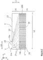
- a heat exchanger 1 of the plate and fin type comprises a stack of plates 2 which extend in two dimensions, length and width, respectively according to the longitudinal direction z and lateral direction y.
- the plates 2 are arranged parallel one above the other with spacing and thus form several sets of passages 3, 4, 5 for fluids F1, F2, F3 to be put into indirect heat exchange relation via the plates 2.
- the lateral direction y is orthogonal to the longitudinal direction z and parallel to the plates 2.
- the longitudinal axis is vertical when the exchanger 1 is in operation.
- each passage has a parallelepipedal and flat shape.
- the passages extend in length in the longitudinal direction z and in width in the lateral direction y.
- the gap between two successive plates is small compared to the length and width of each successive plate.
- Each passage 3, 4, 5 is divided, along the longitudinal direction z, into at least one distribution zone 20 and one heat exchange zone 21.
- the flow of fluids within the distribution zones takes place generally parallel to the longitudinal direction z.
- the heat distribution and exchange zones 20, 21 are preferably juxtaposed along the longitudinal axis z.
- two distribution zones 20 are arranged on either side of the heat exchange zone 21, one serving to bring the fluid F1 to the heat exchange zone 21, the other to be evacuated from said zone.
- Conventional distribution waves produced in the form of corrugated products are shown in distribution zones 20.
- the exchanger 1 comprises collectors of semi-tubular shape 7, 9 provided with openings 10 for the introduction of fluids into the exchanger 1 and the evacuation of the fluids out of the exchanger 1. These collectors have openings that are narrower than the passages.
- the distribution zones 20 serve to distribute the fluids introduced through the openings of the manifolds over the entire width of the passages.
- a distribution element is arranged in at least one distribution zone 20 of a passage 3 of the exchanger, this element comprising a plurality of separating walls 25 arranged so as to dividing said distribution zone 20 into a plurality of channels 26 for the flow of the fluid F1.
- Said channels 26 define flow paths of different lengths and have variable fluid passage sections along said flow paths.
- the distribution element gives structural rigidity to the distribution zone of the exchanger since the spacer function can be provided by the dividing walls.
- the exchanger is of the brazed plate and fin type, that is to say that the separate elements constituting the exchanger are joined together, directly or indirectly by brazing.
- the distribution element according to the invention is distinct from the plates 2.
- brazed support is meant that the support is bonded or secured by brazing with an adjacent plate of the exchanger via at least a portion of their respective surfaces.
- fluid passage section is understood to mean the surface through which the fluid flows within the channel, the latter being measured in a plane perpendicular to the direction of movement of the fluid F1 in said channel, i. e. perpendicular to the current lines of the fluid F1 in motion.
- the length of the flow paths means the distance to be traveled for the fluid F1 between the inlet and the outlet of the channel considered.
- the distribution element further comprises a support 27 configured to hold the walls 25 integral with one another.
- a support 27 configured to hold the walls 25 integral with one another. An example of such an element is shown on the Figure 5B .
- the distribution element is not a corrugated product as is the case with distribution waves conventionally arranged in the distribution zones of a brazed plate and fin heat exchanger.
- the walls 25 are made integral with one another via the same support 27, which confers greater rigidity on the distribution element. This also makes it possible to simplify the brazing operations. In addition, such a configuration offers greater freedom of construction of the distribution element and of the geometry of its channels.
- walls 25 of a relatively large height in the passages typically at least 2 mm, preferably at least 5 mm, more preferably up to 15 mm, or even more, which is not necessary. not the case with exchangers in which the walls result from stamping of the separator plates.
- said support comprises a bottom 27, preferably a flat bottom which can be formed from a flat sheet, from which the dividing walls 25 are erected.
- the walls 25 are preferably erected in the vertical direction x.
- the walls 25 can have heights h typically between 2 and 15 mm. Preferably, the heights are chosen so that the walls 25 extend in almost all, if not all, of the height of the passage in the vertical direction x.
- the configuration of the distribution element 22 according to the invention in which the distribution element is a separate part from the plates, also makes it possible to design separate distribution profiles on either side of the same plate.
- a distribution element according to the invention is housed in several, or even all, of the distribution zones of one or more sets of passages of the exchanger. Said element extends over almost all, or even all, of the height of the passages, measured along the vertical direction x, so that the structure is advantageously in contact with each plate 2 forming the passage 20.
- the channels are preferably fluidly isolated from each other.
- the flow parameters of each channel are thus controlled independently of those of neighboring channels, which makes it possible to adjust specifies the distribution of the fluid over the width of the passages at the outlet of the distribution zone.
- the dividing walls 25 are erected perpendicular to the plates 2.
- the number of channels 26 is at least 6, more preferably between 5 and 50. Indeed, the number of channels 26 must, on the one hand, be sufficient to give the element 22 its rigidity. mechanical and, on the other hand, not to be excessive in order to leave free a sufficient volume for the flow of the fluid and to limit the pressure drops.
- the distribution element 22 comprises a first end 23 forming an inlet or an outlet for the fluid F1 and a second end 24 in fluid communication with the heat exchange zone 21.
- the passages 3 to 5 are bordered by closing bars 6 which do not completely block the passages but leave free openings 23, 24 for the entry or exit of the corresponding fluids.
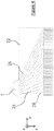
- the Figure 2 partially schematizes the “inlet” part of a passage 3 of an exchanger according to one embodiment of the invention.
- a fluid manifold 7 is arranged in the left corner of the exchanger, the first end 23 being fluidly connected to the manifold 7 and forming an inlet for the fluid F1, the flow of which is shown schematically by dotted arrows.
- the first and second ends 23, 24 preferably extend in a plane parallel to the lateral direction y and perpendicular to the longitudinal direction z.
- the dividing walls 25 extend between the first and second ends 23, 24 and form channels 26 opening out at the level of the second end 24 and configured to uniformly distribute, in the lateral direction y, the fluid F1 so as to obtain a distribution homogeneous or almost homogeneous towards or from the entire width of the heat exchange zone 21 when the other of said first and second ends 23, 24 is supplied with fluid F1.
- each channel is provided with first openings 26a and second openings 26b.
- the first and second openings 26a, 26b are located at the first and second ends 23, 24 respectively, the walls separators 25 extending continuously from the first end 23 to the second end 24.
- the flow path of the fluid F1 corresponds to the path to be traversed between the openings 26a and 26b.
- Each of the ends 23, 24 can thus be divided into a series of openings 26a and a series of openings 26b respectively.
- the openings 26a, 26b of the channels 26 may have identical or variable fluid passage sections depending on the channels 26 considered.
- the fluid passage sections of the openings 26a and 26b correspond to the internal surfaces of the channels 26 measured at the first and second ends 23, 24 in a plane parallel to the lateral direction y.
- At least one first opening 26a has a fluid passage section different from the fluid passage section of another first opening 26a and / or at least one second opening 26b has a fluid passage section different from the one. fluid passage section of another second opening 26b.
- first openings 26a and / or the second openings 26b of the same channel 26 have fluid passage sections that are all the larger as the flow path defined by said channel 26 is long, i. e. that the distance to be traveled for the fluid F1 between the first opening 26a and the second opening 26b is large.
- the first end 23 is subdivided into a first series of first openings 26a having increasing fluid passage sections along the y direction.
- lateral direction y This promotes the supply of the channels configured to distribute the fluid F1 from the manifold 7 to the part of the second end 23 diagonally opposite to said end edge.
- the first openings 26a arranged, preferably symmetrically, on either side of the plane M have sections of fluid passage increasing as one moves away from said median plane M.
- the first end 23 is located on the side of the inlet manifold 7 of the exchanger and forms an inlet for the fluid F1.
- the first openings 26a of the first end 23 have variable fluid passage sections depending on their position along the lateral direction y.
- openings 26a of different passage sections Thanks to the use of openings 26a of different passage sections, it is in particular possible to supercharge channels less conducive to the passage of the fluid, and this as soon as the fluid F1 enters the distribution zone 20, which generates less pressure drops and therefore leads to a more efficient fluid distribution system.
- all or part of the channels 26 comprise means 28 for modifying the linear resistance to flow of said channels 26.
- the linear resistance to flow of each channel can thus be adjusted according to the desired flow characteristics in each channel 26, in particular fluid flow rate and velocity.
- the linear resistance to flow of the channels can be adjusted so that each channel 26 has a similar overall resistance to flow.
- the characteristics of the fluid leaving the channels 26 are thus homogenized in the lateral direction y, which allows uniform distribution towards or from the heat exchange zone 21.
- resistance to flow is understood to mean the capacity of the channel to generate, on the one hand, viscous friction and, on the other hand, to deflect the flow (pressure force normal to the wall).
- This resistance is expressed in the form of a reaction force of the solid structure on the flow in Newtons, which results in the fluid by a pressure drop in Pascals. This force depends on the first order of the kinetic energy of the fluid (rho * u 2 ) and on the second order of the Reynolds number (rho * u * D / mu).
- Linear flow resistance corresponds to the resistance to flow of the channel expressed per unit length.
- a channel 26 will include modification means 28 configured to produce an increase in the linear resistance to flow that is all the greater as the opening 26a of said channel is close, in terms of the distance to be traveled for the fluid F1, of the other opening 26b.
- the channels 26 comprise modifying means 28 configured to produce an increase in the linear resistance to the flow which decreases and decreases in the lateral direction y. Indeed, this makes it possible to compensate for the natural preferential passage of the fluid in the axis rather than by the side of the exchanger, and therefore to obtain a good distribution of the fluid.
- the collector 7 is centered with respect to the median plane M of the exchanger, as shown in Figure 5A , the fluid resistance of a channel will be all the greater the closer it is to the median plane M.
- the channels 26 may have internal profiles shaped to produce different variations in flow resistance.
- Obstacles 28 producing different resistance to flow can also be arranged within one or more channels 26.
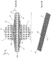
- the insertion of a porous structure 28, for example a metal foam, within a channel will make it possible to increase its resistance to flow. It will thus be possible to adjust the linear resistance to the flow of the channels 26, by varying the characteristics of the structures 28 inserted, such as volume, density, etc. depending on the channels. In the example shown on Figure 3B , the volume occupied by the porous structures 28 decreases along the lateral direction y, so as to produce smaller variations in linear resistance to flow along y.
- partitions 28 can be arranged in one or more channels 26 so as to create an additional division stage of the distribution zone 22. This makes it possible to vary the linear resistance to flow as well as to control the parameters even more finely. flow of the fluid distributed to or recovered from the heat exchange zone 21.
- the use of additional partitions 28 is particularly advantageous when the first end 23 of the distribution element has too small a width to be able to be divided into a sufficient number of channels 26.
- the dividing walls 25 and / or the partitions 28 may have, in longitudinal section, rectilinear profiles, as illustrated in the figures.
- the dividing walls 25 have predetermined curvilinear profiles comprising at least one inflection point P.
- Such a geometry makes it possible to deflect the fluid more quickly, that is to say over a shorter distance L1, and this over a large width of the passage of the exchanger. It is thus possible to reduce the longitudinal extent of the distribution zone 20, and consequently to increase the mechanical strength of the exchanger since the compactness of the so-called “weak” zone of the exchanger is increased.
- the first end 23 forming the inlet or outlet of the distribution element 22 has, along the lateral direction y, a width L3 of between 50 and 1000 mm, more preferably of between 100 and 500 mm.
- the distribution element 22 has, parallel to the longitudinal direction z, a length L1 of less than 500 mm, preferably between 50 and 200 mm, more preferably between 80 and 100 mm.
- the length L1 of the distribution element 22 represents less than 20% of the length of the exchange zone 21.
- the distribution element 22 has, parallel to the lateral direction y, a width L2, the ratio between a length L1 and the width L2 being less than 20%, preferably between 5 and 10%.
- the width L2 is preferably between 500 and 1500 mm.
- the distribution element 22 is advantageously formed of a metallic material, preferably aluminum or an aluminum alloy.
- the element can be formed in particular of a porous material, preferably with non-opening pores, for example a metallic foam.
- the distribution element 22 is monolithic, which makes it possible to minimize accidents along the fluid flow paths.
- the element 22 can be manufactured by an additive manufacturing method, preferably by thermal spraying, which makes it possible to produce parts of complex geometries as a single block.
- thermal spraying preferably by thermal spraying
- a so-called “ cold spray” cold spraying process can be used.
- additive manufacturing process can also be designated by the terms “3D printing” or “three-dimensional printing”.
- Additive manufacturing makes it possible to produce a real object, using a specific printer that deposits and / or solidifies material, layer by layer, to obtain the final part. Stacking these layers creates a volume.
- the distribution element 22 can be manufactured by a foundry. This manufacturing process makes it possible to produce parts with complex geometries at a relatively low cost compared to additive manufacturing.
- the element 22 is formed from an aluminum alloy for foundry, that is to say an alloy whose main constituent is aluminum, of lower density than intended to be transformed by techniques of foundry.
- these advantageously comprise heat exchange structures 8 arranged between the plates 2, as shown in FIG. Figure 1 .
- These structures have the function of increasing the heat exchange surface area of the exchanger. and play the role of spacers between the plates 2, in particular during assembly by brazing the exchanger, to prevent any deformation of the plates during the use of fluids under pressure.
- these structures comprise heat exchange waves 8 which advantageously extend along the width and the length of the passages of the exchanger, parallel to the plates 2.
- These waves 8 can be formed in the form of corrugated sheets.
- the wave legs which connect the successive vertices and bases of the wave are called “fins”.
- the exchange structures 8 can also take other particular shapes defined according to the desired fluid flow characteristics. More generally, the term "fins" covers blades or other secondary heat exchange surfaces, which extend from the primary heat exchange surfaces, that is to say the plates of the exchanger, in the passages of the exchanger.
- the distribution element 22 according to the invention and the heat exchange structure 8 are preferably juxtaposed along the longitudinal axis z, that is to say positioned end to end. It being noted that a small clearance may exist between these elements, in order not to block the channels of the exchange zone 21 which are opposite the walls 25 of the channels of the distribution zone 22.
- the first end 23 of element 22 is arranged end-to-end with at least part of manifold 7 while second end 24 is arranged end-to-end with at least part of structure 8.
- structure 8 , the collector 7 and / or the element 22 are linked by brazing to the plates 2 and are linked indirectly to each other via their respective links with the plates 2.
- the element 22 is assembled to the plates 2 by brazing the support 27 to the plates.
- plates 2, the support or bottom 27 comprising at least one face coated with a brazing agent. This face is positioned facing a plate 2 so as to form a connecting surface with said plate 2.
- the plates 2 have in all or part at least one face coated at least in part with a brazing agent layer.
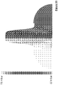
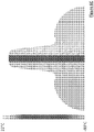
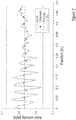
- the results of these simulations are presented on the Figures 6A , 6B , 6C and 7 .
- the Figures 6A , 6B and 6C represent the maps of the speeds, pressures and temperatures of the fluid flowing within the channels 26 of the distribution element 22. There is a quasi-homogeneous distribution of the fluid at the outlet of the channels 26.
- the Figure 7 shows the development of said axial velocity values ( "axial velocity"), that is to say in the longitudinal direction z, obtained at the output of element 22, depending on the position in the lateral direction y. We thus start from the center of the distribution element 22 (position at 0 mm) to the edge of the second end 23 (position at 485 mm).
- the distribution of the speed values along the lateral direction y is characterized by a standard deviation (or standard deviation) of 0.9% and a maximum deviation of 2.8% from the mean value of the speed in the zone d 'exchange, which is much lower than the variations observed with conventional distribution elements for which the standard deviations are of the order of 3%. Thanks to the invention, the variations in speed are therefore reduced in the lateral direction at the outlet of the distribution zone, which makes it possible to distribute the fluid as homogeneously as possible over the entire width of the heat exchange zone. heat.
- a distribution element according to the invention can thus be arranged in any distribution zone of the exchanger, in one or more series of passages 3, 4, 5 of the exchanger, upstream and / or downstream of one or more several of the heat exchanger manifolds.
- FIG. 5B illustrates the case where an exchanger passage comprises two distribution elements according to the invention arranged on either side of the heat exchange zone 21 (shown diagrammatically with a deliberately shortened length). It should also be noted that passages 3, 4, 5 of the exchanger can equally well be formed between two successive plates 2 or between a closing bar 6 of the exchanger and an immediately adjacent plate 2.
Landscapes
- Engineering & Computer Science (AREA)
- Physics & Mathematics (AREA)
- Thermal Sciences (AREA)
- Mechanical Engineering (AREA)
- General Engineering & Computer Science (AREA)
- Geometry (AREA)
- Heat-Exchange Devices With Radiators And Conduit Assemblies (AREA)
- Details Of Heat-Exchange And Heat-Transfer (AREA)
Claims (17)
- Gelöteter Wärmeaustauscher (1) vom Typ mit Platten und Rippen, umfassend:- eine Mehrzahl von Platten (2), die parallel zueinander so angeordnet sind, dass sie mindestens eine Anordnung von Durchgängen (3) zur Strömung eines Fluids (F1) definieren, die dazu bestimmt ist, Wärme mit mindestens einem anderen Fluid (F2) auszutauschen, wobei sich die Durchgänge (3) in einer Längsrichtung (z) und einer seitlichen Richtung (x) senkrecht zur Längsrichtung (z) erstrecken,- wobei jeder Durchgang (3) in der Längsrichtung (z) in mindestens eine Verteilungszone (20) und eine Wärmeaustauschzone (21) unterteilt ist,- wobei mindestens eine Verteilungszone (20) eines Durchgangs (3) ein Verteilungselement (22) umfasst, wobei das Verteilungselement (22) eine Mehrzahl von Trennwänden (25) umfasst, die so angeordnet sind, dass sie die Verteilungszone (20) in eine Mehrzahl von Kanälen (26) zur Strömung des Fluids (F1) aufteilen, wobei die Kanäle (26) Strömungswege unterschiedlicher Längen definieren und Fluid-Durchgangsquerschnitte aufweisen, die entlang der Strömungswege variabel sind,
wobei die Trennwände (25) des Verteilungselements (22) mittels eines Trägers (27) fest miteinander verbunden sind, wobei der Träger (27) mit einer benachbarten Platte (2) verlötet ist. - Austauscher nach Anspruch 1, dadurch gekennzeichnet, dass die Trennwände (25) vom Träger (27) in den Durchgang (3) ragen.
- Austauscher nach Anspruch 2, dadurch gekennzeichnet, dass der Träger (27) einen ebenen Boden (27) umfasst, wobei die Trennwände (25) senkrecht zum Boden (27) abstehen.
- Austauscher nach einem der vorhergehenden Ansprüche, dadurch gekennzeichnet, dass er ein erstes Ende (23), das einen Ein- oder Ausgang für das Fluid (F1) bildet, und ein zweites Ende (24), das mit der Wärmeaustauschzone (21) in Fluidverbindung steht, wenn das Verteilungselement in einer Verteilungszone (20) angeordnet ist, umfasst, wobei jede Trennwand (25) einstückig ausgebildet ist und sich durchgehend von dem ersten Ende (23) bis zum zweiten Ende (24) erstreckt.
- Austauscher nach Anspruch 4, dadurch gekennzeichnet, dass jeder Kanal (26) mit einer ersten Öffnung (26a) und einer zweiten Öffnung (26b) versehen ist, die sich am ersten bzw. zweiten Ende (23, 24) befinden, wobei mindestens eine erste Öffnung (26a) einen Fluid-Durchgangsquerschnitt aufweist, der sich vom Fluid-Durchgangsquerschnitt einer anderen ersten Öffnung (26a) unterscheidet, und/oder mindestens eine zweite Öffnung (26b) einen Fluid-Durchgangsquerschnitt aufweist, der sich vom Fluid-Durchgangsquerschnitt einer anderen zweiten Öffnung (26b) unterscheidet.
- Austauscher nach Anspruch 5, dadurch gekennzeichnet, dass die ersten Öffnungen (26a) und/oder die zweiten Öffnungen (26b) eines selben Kanals (26) Fluid-Durchgangsquerschnitte aufweisen, die um so größer sind, je länger der Strömungsweg ist, der vom Kanal (26) definiert ist.
- Austauscher nach einem der vorhergehenden Ansprüche, dadurch gekennzeichnet, dass ein oder mehrere Kanäle (26) Mittel (28) zur Änderung des längenbezogenen Strömungswiderstands der Kanäle (26) umfassen.
- Austauscher nach Anspruch 7, dadurch gekennzeichnet, dass die Mittel (28) eine Ausbildung der Innenprofile der Kanäle (26) umfassen.
- Austauscher nach einem der Ansprüche 7 oder 8, dadurch gekennzeichnet, dass die Mittel (28) Wandungen (28) umfassen, die innerhalb der Kanäle (26) angeordnet sind.
- Austauscher nach einem der Ansprüche 7 bis 9, dadurch gekennzeichnet, dass die Mittel (28) poröse Strukturen umfassen, zum Beispiel Metallschäume, die innerhalb der Kanäle (26) angeordnet sind.
- Austauscher nach einem der vorhergehenden Ansprüche, dadurch gekennzeichnet, dass die Trennwände (25) im Längsschnitt geradlinige Profile aufweisen.
- Austauscher nach einem der Ansprüche 1 bis 10, dadurch gekennzeichnet, dass die Trennwände (25) im Längsschnitt vorbestimmte krummlinige Profile aufweisen.
- Austauscher nach Anspruch 12, dadurch gekennzeichnet, dass die vorbestimmten krummlinigen Profile mindestens einen Wendepunkt (P) aufweisen.
- Austauscher nach einem der vorhergehenden Ansprüche, dadurch gekennzeichnet, dass sich das Verteilungselement (22) auf einer Länge (L1) in einer Längsrichtung (z) und auf einer Breite (L2) in einer seitlichen Richtung (y) erstreckt, wobei das Verhältnis zwischen einer Länge (L1) und der Breite (L2) weniger als 20 %, vorzugsweise zwischen 5 und 10 % beträgt.
- Austauscher nach einem der vorhergehenden Ansprüche, dadurch gekennzeichnet, dass sich das Verteilungselement (22) auf einer Länge (L1) unter 500 mm, vorzugsweise zwischen 50 und 200 mm erstreckt.
- Austauscher nach einem der vorhergehenden Ansprüche, dadurch gekennzeichnet, dass das Verteilungselement (22) eine Höhe, gemessen in einer vertikalen Richtung (x) orthogonal zu den Platten (2), von mindestens 2 mm, vorzugsweise mindestens 5 mm, vorzugsweise eine Höhe zwischen 2 und 15 mm aufweist.
- Austauscher nach einem der vorhergehenden Ansprüche, dadurch gekennzeichnet, dass das Verteilungselement (22) ein monolitisches Element ist, das vorzugsweise mittels eines additiven Fertigungsverfahrens oder Gusstechnik gefertigt ist.
Applications Claiming Priority (2)
| Application Number | Priority Date | Filing Date | Title |
|---|---|---|---|
| FR1757539A FR3069918B1 (fr) | 2017-08-04 | 2017-08-04 | Echangeur de chaleur comprenant un element de distribution a canaux multiples |
| PCT/FR2018/051804 WO2019025691A1 (fr) | 2017-08-04 | 2018-07-16 | Echangeur de chaleur comprenant un element de distribution a canaux multiples |
Publications (2)
| Publication Number | Publication Date |
|---|---|
| EP3662222A1 EP3662222A1 (de) | 2020-06-10 |
| EP3662222B1 true EP3662222B1 (de) | 2021-05-26 |
Family
ID=60515515
Family Applications (1)
| Application Number | Title | Priority Date | Filing Date |
|---|---|---|---|
| EP18755512.3A Active EP3662222B1 (de) | 2017-08-04 | 2018-07-16 | Wärmetauscher avec distriteur |
Country Status (6)
| Country | Link |
|---|---|
| US (1) | US20200370836A1 (de) |
| EP (1) | EP3662222B1 (de) |
| JP (1) | JP7150819B2 (de) |
| CN (1) | CN111065879B (de) |
| FR (1) | FR3069918B1 (de) |
| WO (1) | WO2019025691A1 (de) |
Families Citing this family (10)
| Publication number | Priority date | Publication date | Assignee | Title |
|---|---|---|---|---|
| DE102018003479A1 (de) * | 2018-04-27 | 2019-10-31 | Linde Aktiengesellschaft | Plattenwärmetauscher, verfahrenstechnische Anlage und Verfahren |
| US11226158B2 (en) * | 2019-04-01 | 2022-01-18 | Hamilton Sundstrand Corporation | Heat exchanger fractal splitter |
| FR3096768B1 (fr) * | 2019-05-29 | 2021-04-30 | Air Liquide | Echangeur-réacteur avec zones de distribution perfectionnées |
| FR3096767B1 (fr) * | 2019-05-31 | 2021-07-30 | Safran | Échangeur thermique a déflection |
| CN114340297B (zh) * | 2020-09-29 | 2025-08-01 | 台达电子工业股份有限公司 | 水冷装置及其集流器 |
| JP7247251B2 (ja) * | 2021-03-30 | 2023-03-28 | 本田技研工業株式会社 | 熱交換器 |
| CN113993346B (zh) * | 2021-10-20 | 2023-01-17 | 联想(北京)有限公司 | 导风装置及导风装置的制造方法 |
| CN116793118A (zh) * | 2023-03-03 | 2023-09-22 | 浙江三花智能控制股份有限公司 | 板式热交换器 |
| US12498184B2 (en) * | 2023-06-08 | 2025-12-16 | Raytheon Technologies Corporation | Uniform chemical milling |
| CN118936203A (zh) * | 2024-09-09 | 2024-11-12 | 空调国际(上海)有限公司 | 换热器翅片及板式换热器 |
Family Cites Families (14)
| Publication number | Priority date | Publication date | Assignee | Title |
|---|---|---|---|---|
| US3291206A (en) * | 1965-09-13 | 1966-12-13 | Nicholson Terence Peter | Heat exchanger plate |
| JPS5447152A (en) * | 1977-09-20 | 1979-04-13 | Kobe Steel Ltd | Heat exchanger unit of plate fin type |
| FR2674947B1 (fr) * | 1991-04-03 | 1998-06-05 | Air Liquide | Procede de vaporisation d'un liquide, echangeur de chaleur pour sa mise en óoeuvre, et application a une installation de distillation d'air a double colonne. |
| NL1000706C2 (nl) * | 1995-06-30 | 1996-12-31 | Level Energietech Bv | Warmtewisselaar met verbeterde configuratie. |
| US6044902A (en) * | 1997-08-20 | 2000-04-04 | Praxair Technology, Inc. | Heat exchange unit for a cryogenic air separation system |
| FR2790546B1 (fr) * | 1999-03-01 | 2001-04-20 | Air Liquide | Echangeur de chaleur, applications a la vaporisation de liquide sous pression et appareil de distillation d'air equipe d'un tel echangeur |
| JP2001235295A (ja) * | 2000-02-21 | 2001-08-31 | Sharp Corp | 熱交換器のヘッダ |
| JP2003222495A (ja) * | 2002-01-31 | 2003-08-08 | Sumitomo Precision Prod Co Ltd | 熱交換用フィン部材およびこれを用いた熱交換装置 |
| SE532524C2 (sv) * | 2008-06-13 | 2010-02-16 | Alfa Laval Corp Ab | Värmeväxlarplatta samt värmeväxlarmontage innefattandes fyra plattor |
| DE102008033302A1 (de) * | 2008-07-15 | 2010-01-21 | Linde Aktiengesellschaft | Ermüdungsfester Plattenwärmetauscher |
| FR2995073A1 (fr) * | 2012-09-05 | 2014-03-07 | Air Liquide | Element d'echangeur pour echangeur de chaleur, echangeur de chaleur comprenant un tel element d'echangeur et procede de fabrication d'un tel element d'echangeur |
| CN102809312A (zh) * | 2012-09-12 | 2012-12-05 | 江苏宝得换热设备有限公司 | 一种三通道板式换热器 |
| EP3150952A1 (de) * | 2015-10-02 | 2017-04-05 | Alfa Laval Corporate AB | Wärmetauschplatte und plattenwärmetauscher |
| US20170198988A1 (en) * | 2016-01-13 | 2017-07-13 | Hamilton Sundstrand Corporation | Vanes for heat exchangers |
-
2017
- 2017-08-04 FR FR1757539A patent/FR3069918B1/fr not_active Expired - Fee Related
-
2018
- 2018-07-16 CN CN201880057974.XA patent/CN111065879B/zh active Active
- 2018-07-16 JP JP2020504359A patent/JP7150819B2/ja active Active
- 2018-07-16 US US16/636,165 patent/US20200370836A1/en not_active Abandoned
- 2018-07-16 WO PCT/FR2018/051804 patent/WO2019025691A1/fr not_active Ceased
- 2018-07-16 EP EP18755512.3A patent/EP3662222B1/de active Active
Also Published As
| Publication number | Publication date |
|---|---|
| JP7150819B2 (ja) | 2022-10-11 |
| CN111065879B (zh) | 2021-08-24 |
| JP2020529572A (ja) | 2020-10-08 |
| FR3069918B1 (fr) | 2020-01-17 |
| FR3069918A1 (fr) | 2019-02-08 |
| US20200370836A1 (en) | 2020-11-26 |
| EP3662222A1 (de) | 2020-06-10 |
| WO2019025691A1 (fr) | 2019-02-07 |
| CN111065879A (zh) | 2020-04-24 |
Similar Documents
| Publication | Publication Date | Title |
|---|---|---|
| EP3662222B1 (de) | Wärmetauscher avec distriteur | |
| EP1709380A1 (de) | Wärmetauscher und entsprechendes austauschmodul | |
| EP4033193B1 (de) | Wärmetauscher mit einem aus einem gyroiden bestehenden austauschkörper | |
| FR2861166A1 (fr) | Echangeur de chaleur utilisant un fluide d'accumulation | |
| EP4089358B1 (de) | Wärmetauscher mit partikelfilter in einem oder mehreren kanälen | |
| WO2018172644A1 (fr) | Echangeur de chaleur avec dispositif melangeur liquide/gaz a portion de canal regulatrice | |
| EP3728976A1 (de) | Abstandselement mit oberflächentexturierung sowie zugehöriger wärmetauscher und herstellungsverfahren | |
| EP3728977B1 (de) | Wärmetauscher mit elementen und platten mit oberflächenstrukturierung | |
| FR3084408A1 (fr) | Echangeur de chaleur et procede de fabrication correspondant | |
| EP4033194B1 (de) | Wärmetauscher mit mindestens einem partikelfilter, zusammenbauverfahren eines solchen wärmetauschers | |
| EP3555544B1 (de) | Wärmetauscher mit einer flüssigkeits-/gasmischvorrichtung mit verbesserter kanalgeometrie | |
| EP3319722A1 (de) | Wärmetauscher und/oder wärmeaustauscher-reaktor mit kanälen mit dünnen wänden dazwischen | |
| FR3140420A1 (fr) | Echangeur de chaleur à structure d’échange thermique améliorée | |
| FR3096768A1 (fr) | Echangeur-réacteur avec zones de distribution perfectionnées | |
| FR3075335B1 (fr) | Echangeur de chaleur avec elements intercalaires superposes | |
| WO2015004359A1 (fr) | Dispositif d'échange thermique et procédé de fabrication d'un tel dispositif | |
| EP3728979A1 (de) | Abstandselement mit oberflächentexturierung, wärmetauscher mit einem solchen element | |
| FR3069919A1 (fr) | Element intercalaire en alliage d'aluminium de fonderie pour un echangeur de chaleur | |
| FR3137752A1 (fr) | Dispositif de régulation thermique, notamment de refroidissement | |
| WO2021123597A1 (fr) | Échangeur de chaleur à passages de fluide optimisés | |
| EP4551888A1 (de) | Vorrichtung zur thermischen regelung, insbesondere zur kühlung | |
| FR3153883A1 (fr) | Echangeur de chaleur a distribution améliorée | |
| FR3099238A1 (fr) | Echangeur de chaleur notamment pour véhicule automobile et procédé de fabrication d’un tel échangeur de chaleur | |
| FR3099239A1 (fr) | Echangeur de chaleur notamment pour véhicule automobile et procédé de fabrication d’un tel échangeur de chaleur | |
| FR3075341A1 (fr) | Echangeur de chaleur avec elements intercalaires a texturation de surface |
Legal Events
| Date | Code | Title | Description |
|---|---|---|---|
| STAA | Information on the status of an ep patent application or granted ep patent |
Free format text: STATUS: UNKNOWN |
|
| STAA | Information on the status of an ep patent application or granted ep patent |
Free format text: STATUS: THE INTERNATIONAL PUBLICATION HAS BEEN MADE |
|
| PUAI | Public reference made under article 153(3) epc to a published international application that has entered the european phase |
Free format text: ORIGINAL CODE: 0009012 |
|
| STAA | Information on the status of an ep patent application or granted ep patent |
Free format text: STATUS: REQUEST FOR EXAMINATION WAS MADE |
|
| 17P | Request for examination filed |
Effective date: 20200304 |
|
| AK | Designated contracting states |
Kind code of ref document: A1 Designated state(s): AL AT BE BG CH CY CZ DE DK EE ES FI FR GB GR HR HU IE IS IT LI LT LU LV MC MK MT NL NO PL PT RO RS SE SI SK SM TR |
|
| AX | Request for extension of the european patent |
Extension state: BA ME |
|
| RIN1 | Information on inventor provided before grant (corrected) |
Inventor name: WAGNER, MARC Inventor name: CRAYSSAC, FREDERIC Inventor name: CADALEN, SEBASTIEN Inventor name: SANIEZ, QUENTIN |
|
| DAV | Request for validation of the european patent (deleted) | ||
| DAX | Request for extension of the european patent (deleted) | ||
| GRAP | Despatch of communication of intention to grant a patent |
Free format text: ORIGINAL CODE: EPIDOSNIGR1 |
|
| STAA | Information on the status of an ep patent application or granted ep patent |
Free format text: STATUS: GRANT OF PATENT IS INTENDED |
|
| INTG | Intention to grant announced |
Effective date: 20210218 |
|
| GRAS | Grant fee paid |
Free format text: ORIGINAL CODE: EPIDOSNIGR3 |
|
| GRAA | (expected) grant |
Free format text: ORIGINAL CODE: 0009210 |
|
| STAA | Information on the status of an ep patent application or granted ep patent |
Free format text: STATUS: THE PATENT HAS BEEN GRANTED |
|
| AK | Designated contracting states |
Kind code of ref document: B1 Designated state(s): AL AT BE BG CH CY CZ DE DK EE ES FI FR GB GR HR HU IE IS IT LI LT LU LV MC MK MT NL NO PL PT RO RS SE SI SK SM TR |
|
| REG | Reference to a national code |
Ref country code: GB Ref legal event code: FG4D Free format text: NOT ENGLISH |
|
| REG | Reference to a national code |
Ref country code: CH Ref legal event code: EP |
|
| REG | Reference to a national code |
Ref country code: AT Ref legal event code: REF Ref document number: 1396652 Country of ref document: AT Kind code of ref document: T Effective date: 20210615 |
|
| REG | Reference to a national code |
Ref country code: DE Ref legal event code: R096 Ref document number: 602018017767 Country of ref document: DE |
|
| REG | Reference to a national code |
Ref country code: IE Ref legal event code: FG4D Free format text: LANGUAGE OF EP DOCUMENT: FRENCH |
|
| REG | Reference to a national code |
Ref country code: LT Ref legal event code: MG9D |
|
| REG | Reference to a national code |
Ref country code: AT Ref legal event code: MK05 Ref document number: 1396652 Country of ref document: AT Kind code of ref document: T Effective date: 20210526 |
|
| PG25 | Lapsed in a contracting state [announced via postgrant information from national office to epo] |
Ref country code: BG Free format text: LAPSE BECAUSE OF FAILURE TO SUBMIT A TRANSLATION OF THE DESCRIPTION OR TO PAY THE FEE WITHIN THE PRESCRIBED TIME-LIMIT Effective date: 20210826 Ref country code: AT Free format text: LAPSE BECAUSE OF FAILURE TO SUBMIT A TRANSLATION OF THE DESCRIPTION OR TO PAY THE FEE WITHIN THE PRESCRIBED TIME-LIMIT Effective date: 20210526 Ref country code: FI Free format text: LAPSE BECAUSE OF FAILURE TO SUBMIT A TRANSLATION OF THE DESCRIPTION OR TO PAY THE FEE WITHIN THE PRESCRIBED TIME-LIMIT Effective date: 20210526 Ref country code: LT Free format text: LAPSE BECAUSE OF FAILURE TO SUBMIT A TRANSLATION OF THE DESCRIPTION OR TO PAY THE FEE WITHIN THE PRESCRIBED TIME-LIMIT Effective date: 20210526 Ref country code: HR Free format text: LAPSE BECAUSE OF FAILURE TO SUBMIT A TRANSLATION OF THE DESCRIPTION OR TO PAY THE FEE WITHIN THE PRESCRIBED TIME-LIMIT Effective date: 20210526 |
|
| REG | Reference to a national code |
Ref country code: NL Ref legal event code: MP Effective date: 20210526 |
|
| PG25 | Lapsed in a contracting state [announced via postgrant information from national office to epo] |
Ref country code: LV Free format text: LAPSE BECAUSE OF FAILURE TO SUBMIT A TRANSLATION OF THE DESCRIPTION OR TO PAY THE FEE WITHIN THE PRESCRIBED TIME-LIMIT Effective date: 20210526 Ref country code: NO Free format text: LAPSE BECAUSE OF FAILURE TO SUBMIT A TRANSLATION OF THE DESCRIPTION OR TO PAY THE FEE WITHIN THE PRESCRIBED TIME-LIMIT Effective date: 20210826 Ref country code: PL Free format text: LAPSE BECAUSE OF FAILURE TO SUBMIT A TRANSLATION OF THE DESCRIPTION OR TO PAY THE FEE WITHIN THE PRESCRIBED TIME-LIMIT Effective date: 20210526 Ref country code: PT Free format text: LAPSE BECAUSE OF FAILURE TO SUBMIT A TRANSLATION OF THE DESCRIPTION OR TO PAY THE FEE WITHIN THE PRESCRIBED TIME-LIMIT Effective date: 20210927 Ref country code: RS Free format text: LAPSE BECAUSE OF FAILURE TO SUBMIT A TRANSLATION OF THE DESCRIPTION OR TO PAY THE FEE WITHIN THE PRESCRIBED TIME-LIMIT Effective date: 20210526 Ref country code: SE Free format text: LAPSE BECAUSE OF FAILURE TO SUBMIT A TRANSLATION OF THE DESCRIPTION OR TO PAY THE FEE WITHIN THE PRESCRIBED TIME-LIMIT Effective date: 20210526 Ref country code: GR Free format text: LAPSE BECAUSE OF FAILURE TO SUBMIT A TRANSLATION OF THE DESCRIPTION OR TO PAY THE FEE WITHIN THE PRESCRIBED TIME-LIMIT Effective date: 20210827 Ref country code: IS Free format text: LAPSE BECAUSE OF FAILURE TO SUBMIT A TRANSLATION OF THE DESCRIPTION OR TO PAY THE FEE WITHIN THE PRESCRIBED TIME-LIMIT Effective date: 20210926 |
|
| PG25 | Lapsed in a contracting state [announced via postgrant information from national office to epo] |
Ref country code: NL Free format text: LAPSE BECAUSE OF FAILURE TO SUBMIT A TRANSLATION OF THE DESCRIPTION OR TO PAY THE FEE WITHIN THE PRESCRIBED TIME-LIMIT Effective date: 20210526 |
|
| PG25 | Lapsed in a contracting state [announced via postgrant information from national office to epo] |
Ref country code: EE Free format text: LAPSE BECAUSE OF FAILURE TO SUBMIT A TRANSLATION OF THE DESCRIPTION OR TO PAY THE FEE WITHIN THE PRESCRIBED TIME-LIMIT Effective date: 20210526 Ref country code: ES Free format text: LAPSE BECAUSE OF FAILURE TO SUBMIT A TRANSLATION OF THE DESCRIPTION OR TO PAY THE FEE WITHIN THE PRESCRIBED TIME-LIMIT Effective date: 20210526 Ref country code: SK Free format text: LAPSE BECAUSE OF FAILURE TO SUBMIT A TRANSLATION OF THE DESCRIPTION OR TO PAY THE FEE WITHIN THE PRESCRIBED TIME-LIMIT Effective date: 20210526 Ref country code: DK Free format text: LAPSE BECAUSE OF FAILURE TO SUBMIT A TRANSLATION OF THE DESCRIPTION OR TO PAY THE FEE WITHIN THE PRESCRIBED TIME-LIMIT Effective date: 20210526 Ref country code: CZ Free format text: LAPSE BECAUSE OF FAILURE TO SUBMIT A TRANSLATION OF THE DESCRIPTION OR TO PAY THE FEE WITHIN THE PRESCRIBED TIME-LIMIT Effective date: 20210526 Ref country code: RO Free format text: LAPSE BECAUSE OF FAILURE TO SUBMIT A TRANSLATION OF THE DESCRIPTION OR TO PAY THE FEE WITHIN THE PRESCRIBED TIME-LIMIT Effective date: 20210526 Ref country code: SM Free format text: LAPSE BECAUSE OF FAILURE TO SUBMIT A TRANSLATION OF THE DESCRIPTION OR TO PAY THE FEE WITHIN THE PRESCRIBED TIME-LIMIT Effective date: 20210526 |
|
| REG | Reference to a national code |
Ref country code: CH Ref legal event code: PL |
|
| REG | Reference to a national code |
Ref country code: DE Ref legal event code: R097 Ref document number: 602018017767 Country of ref document: DE |
|
| PLBE | No opposition filed within time limit |
Free format text: ORIGINAL CODE: 0009261 |
|
| STAA | Information on the status of an ep patent application or granted ep patent |
Free format text: STATUS: NO OPPOSITION FILED WITHIN TIME LIMIT |
|
| PG25 | Lapsed in a contracting state [announced via postgrant information from national office to epo] |
Ref country code: MC Free format text: LAPSE BECAUSE OF FAILURE TO SUBMIT A TRANSLATION OF THE DESCRIPTION OR TO PAY THE FEE WITHIN THE PRESCRIBED TIME-LIMIT Effective date: 20210526 |
|
| REG | Reference to a national code |
Ref country code: BE Ref legal event code: MM Effective date: 20210731 |
|
| PG25 | Lapsed in a contracting state [announced via postgrant information from national office to epo] |
Ref country code: LI Free format text: LAPSE BECAUSE OF NON-PAYMENT OF DUE FEES Effective date: 20210731 Ref country code: CH Free format text: LAPSE BECAUSE OF NON-PAYMENT OF DUE FEES Effective date: 20210731 |
|
| 26N | No opposition filed |
Effective date: 20220301 |
|
| PG25 | Lapsed in a contracting state [announced via postgrant information from national office to epo] |
Ref country code: IS Free format text: LAPSE BECAUSE OF FAILURE TO SUBMIT A TRANSLATION OF THE DESCRIPTION OR TO PAY THE FEE WITHIN THE PRESCRIBED TIME-LIMIT Effective date: 20210926 Ref country code: LU Free format text: LAPSE BECAUSE OF NON-PAYMENT OF DUE FEES Effective date: 20210716 Ref country code: AL Free format text: LAPSE BECAUSE OF FAILURE TO SUBMIT A TRANSLATION OF THE DESCRIPTION OR TO PAY THE FEE WITHIN THE PRESCRIBED TIME-LIMIT Effective date: 20210526 |
|
| PG25 | Lapsed in a contracting state [announced via postgrant information from national office to epo] |
Ref country code: IT Free format text: LAPSE BECAUSE OF FAILURE TO SUBMIT A TRANSLATION OF THE DESCRIPTION OR TO PAY THE FEE WITHIN THE PRESCRIBED TIME-LIMIT Effective date: 20210526 Ref country code: IE Free format text: LAPSE BECAUSE OF NON-PAYMENT OF DUE FEES Effective date: 20210716 Ref country code: BE Free format text: LAPSE BECAUSE OF NON-PAYMENT OF DUE FEES Effective date: 20210731 |
|
| GBPC | Gb: european patent ceased through non-payment of renewal fee |
Effective date: 20220716 |
|
| PG25 | Lapsed in a contracting state [announced via postgrant information from national office to epo] |
Ref country code: GB Free format text: LAPSE BECAUSE OF NON-PAYMENT OF DUE FEES Effective date: 20220716 |
|
| PG25 | Lapsed in a contracting state [announced via postgrant information from national office to epo] |
Ref country code: CY Free format text: LAPSE BECAUSE OF FAILURE TO SUBMIT A TRANSLATION OF THE DESCRIPTION OR TO PAY THE FEE WITHIN THE PRESCRIBED TIME-LIMIT Effective date: 20210526 |
|
| PG25 | Lapsed in a contracting state [announced via postgrant information from national office to epo] |
Ref country code: HU Free format text: LAPSE BECAUSE OF FAILURE TO SUBMIT A TRANSLATION OF THE DESCRIPTION OR TO PAY THE FEE WITHIN THE PRESCRIBED TIME-LIMIT; INVALID AB INITIO Effective date: 20180716 |
|
| PG25 | Lapsed in a contracting state [announced via postgrant information from national office to epo] |
Ref country code: MK Free format text: LAPSE BECAUSE OF FAILURE TO SUBMIT A TRANSLATION OF THE DESCRIPTION OR TO PAY THE FEE WITHIN THE PRESCRIBED TIME-LIMIT Effective date: 20210526 |
|
| PG25 | Lapsed in a contracting state [announced via postgrant information from national office to epo] |
Ref country code: TR Free format text: LAPSE BECAUSE OF FAILURE TO SUBMIT A TRANSLATION OF THE DESCRIPTION OR TO PAY THE FEE WITHIN THE PRESCRIBED TIME-LIMIT Effective date: 20210526 |
|
| PG25 | Lapsed in a contracting state [announced via postgrant information from national office to epo] |
Ref country code: MT Free format text: LAPSE BECAUSE OF FAILURE TO SUBMIT A TRANSLATION OF THE DESCRIPTION OR TO PAY THE FEE WITHIN THE PRESCRIBED TIME-LIMIT Effective date: 20210526 |
|
| PGFP | Annual fee paid to national office [announced via postgrant information from national office to epo] |
Ref country code: DE Payment date: 20250722 Year of fee payment: 8 |
|
| PGFP | Annual fee paid to national office [announced via postgrant information from national office to epo] |
Ref country code: FR Payment date: 20250725 Year of fee payment: 8 |