EP3662222B1 - Heat exchanger with distributing element - Google Patents
Heat exchanger with distributing element Download PDFInfo
- Publication number
- EP3662222B1 EP3662222B1 EP18755512.3A EP18755512A EP3662222B1 EP 3662222 B1 EP3662222 B1 EP 3662222B1 EP 18755512 A EP18755512 A EP 18755512A EP 3662222 B1 EP3662222 B1 EP 3662222B1
- Authority
- EP
- European Patent Office
- Prior art keywords
- fluid
- heat exchanger
- distribution
- exchanger according
- channels
- Prior art date
- Legal status (The legal status is an assumption and is not a legal conclusion. Google has not performed a legal analysis and makes no representation as to the accuracy of the status listed.)
- Active
Links
- 238000009826 distribution Methods 0.000 claims description 136
- 239000012530 fluid Substances 0.000 claims description 109
- 238000004519 manufacturing process Methods 0.000 claims description 10
- 239000000654 additive Substances 0.000 claims description 8
- 230000000996 additive effect Effects 0.000 claims description 8
- 238000005192 partition Methods 0.000 claims description 5
- 239000006262 metallic foam Substances 0.000 claims description 4
- 238000005266 casting Methods 0.000 claims 1
- 238000005219 brazing Methods 0.000 description 9
- IJGRMHOSHXDMSA-UHFFFAOYSA-N Atomic nitrogen Chemical compound N#N IJGRMHOSHXDMSA-UHFFFAOYSA-N 0.000 description 5
- 238000004088 simulation Methods 0.000 description 5
- 238000000034 method Methods 0.000 description 4
- 229910052782 aluminium Inorganic materials 0.000 description 3
- XAGFODPZIPBFFR-UHFFFAOYSA-N aluminium Chemical compound [Al] XAGFODPZIPBFFR-UHFFFAOYSA-N 0.000 description 3
- 238000004891 communication Methods 0.000 description 3
- 230000007423 decrease Effects 0.000 description 3
- 230000008021 deposition Effects 0.000 description 3
- 235000021183 entrée Nutrition 0.000 description 3
- 239000007789 gas Substances 0.000 description 3
- 239000000203 mixture Substances 0.000 description 3
- 238000000926 separation method Methods 0.000 description 3
- 125000006850 spacer group Chemical group 0.000 description 3
- 238000010146 3D printing Methods 0.000 description 2
- 229910000838 Al alloy Inorganic materials 0.000 description 2
- XKRFYHLGVUSROY-UHFFFAOYSA-N Argon Chemical compound [Ar] XKRFYHLGVUSROY-UHFFFAOYSA-N 0.000 description 2
- QVGXLLKOCUKJST-UHFFFAOYSA-N atomic oxygen Chemical compound [O] QVGXLLKOCUKJST-UHFFFAOYSA-N 0.000 description 2
- 239000003795 chemical substances by application Substances 0.000 description 2
- 239000000470 constituent Substances 0.000 description 2
- 239000007788 liquid Substances 0.000 description 2
- VNWKTOKETHGBQD-UHFFFAOYSA-N methane Chemical compound C VNWKTOKETHGBQD-UHFFFAOYSA-N 0.000 description 2
- 238000012986 modification Methods 0.000 description 2
- 230000004048 modification Effects 0.000 description 2
- 229910052757 nitrogen Inorganic materials 0.000 description 2
- 239000001301 oxygen Substances 0.000 description 2
- 229910052760 oxygen Inorganic materials 0.000 description 2
- 239000011148 porous material Substances 0.000 description 2
- 238000011084 recovery Methods 0.000 description 2
- 238000009827 uniform distribution Methods 0.000 description 2
- 238000011144 upstream manufacturing Methods 0.000 description 2
- 241000195940 Bryophyta Species 0.000 description 1
- 241001080024 Telles Species 0.000 description 1
- 229910045601 alloy Inorganic materials 0.000 description 1
- 239000000956 alloy Substances 0.000 description 1
- 229910052786 argon Inorganic materials 0.000 description 1
- 238000010288 cold spraying Methods 0.000 description 1
- 238000010276 construction Methods 0.000 description 1
- 238000013461 design Methods 0.000 description 1
- 238000011161 development Methods 0.000 description 1
- 238000010586 diagram Methods 0.000 description 1
- 238000005516 engineering process Methods 0.000 description 1
- 230000004927 fusion Effects 0.000 description 1
- 229930195733 hydrocarbon Natural products 0.000 description 1
- 150000002430 hydrocarbons Chemical class 0.000 description 1
- 238000003780 insertion Methods 0.000 description 1
- 230000037431 insertion Effects 0.000 description 1
- 239000000463 material Substances 0.000 description 1
- 239000007769 metal material Substances 0.000 description 1
- 239000012768 molten material Substances 0.000 description 1
- 235000011929 mousse Nutrition 0.000 description 1
- 239000003345 natural gas Substances 0.000 description 1
- 239000000843 powder Substances 0.000 description 1
- 230000005855 radiation Effects 0.000 description 1
- 238000000110 selective laser sintering Methods 0.000 description 1
- 239000007787 solid Substances 0.000 description 1
- 239000007921 spray Substances 0.000 description 1
- 238000007751 thermal spraying Methods 0.000 description 1
Images


Classifications
-
- F—MECHANICAL ENGINEERING; LIGHTING; HEATING; WEAPONS; BLASTING
- F28—HEAT EXCHANGE IN GENERAL
- F28F—DETAILS OF HEAT-EXCHANGE AND HEAT-TRANSFER APPARATUS, OF GENERAL APPLICATION
- F28F9/00—Casings; Header boxes; Auxiliary supports for elements; Auxiliary members within casings
- F28F9/02—Header boxes; End plates
- F28F9/026—Header boxes; End plates with static flow control means, e.g. with means for uniformly distributing heat exchange media into conduits
- F28F9/0282—Header boxes; End plates with static flow control means, e.g. with means for uniformly distributing heat exchange media into conduits by varying the geometry of conduit ends, e.g. by using inserts or attachments for modifying the pattern of flow at the conduit inlet or outlet
-
- F—MECHANICAL ENGINEERING; LIGHTING; HEATING; WEAPONS; BLASTING
- F25—REFRIGERATION OR COOLING; COMBINED HEATING AND REFRIGERATION SYSTEMS; HEAT PUMP SYSTEMS; MANUFACTURE OR STORAGE OF ICE; LIQUEFACTION SOLIDIFICATION OF GASES
- F25J—LIQUEFACTION, SOLIDIFICATION OR SEPARATION OF GASES OR GASEOUS OR LIQUEFIED GASEOUS MIXTURES BY PRESSURE AND COLD TREATMENT OR BY BRINGING THEM INTO THE SUPERCRITICAL STATE
- F25J5/00—Arrangements of cold exchangers or cold accumulators in separation or liquefaction plants
- F25J5/002—Arrangements of cold exchangers or cold accumulators in separation or liquefaction plants for continuously recuperating cold, i.e. in a so-called recuperative heat exchanger
-
- F—MECHANICAL ENGINEERING; LIGHTING; HEATING; WEAPONS; BLASTING
- F28—HEAT EXCHANGE IN GENERAL
- F28D—HEAT-EXCHANGE APPARATUS, NOT PROVIDED FOR IN ANOTHER SUBCLASS, IN WHICH THE HEAT-EXCHANGE MEDIA DO NOT COME INTO DIRECT CONTACT
- F28D9/00—Heat-exchange apparatus having stationary plate-like or laminated conduit assemblies for both heat-exchange media, the media being in contact with different sides of a conduit wall
- F28D9/0062—Heat-exchange apparatus having stationary plate-like or laminated conduit assemblies for both heat-exchange media, the media being in contact with different sides of a conduit wall the conduits for one heat-exchange medium being formed by spaced plates with inserted elements
-
- F—MECHANICAL ENGINEERING; LIGHTING; HEATING; WEAPONS; BLASTING
- F28—HEAT EXCHANGE IN GENERAL
- F28F—DETAILS OF HEAT-EXCHANGE AND HEAT-TRANSFER APPARATUS, OF GENERAL APPLICATION
- F28F9/00—Casings; Header boxes; Auxiliary supports for elements; Auxiliary members within casings
- F28F9/02—Header boxes; End plates
- F28F9/026—Header boxes; End plates with static flow control means, e.g. with means for uniformly distributing heat exchange media into conduits
- F28F9/0265—Header boxes; End plates with static flow control means, e.g. with means for uniformly distributing heat exchange media into conduits by using guiding means or impingement means inside the header box
- F28F9/0268—Header boxes; End plates with static flow control means, e.g. with means for uniformly distributing heat exchange media into conduits by using guiding means or impingement means inside the header box in the form of multiple deflectors for channeling the heat exchange medium
-
- F—MECHANICAL ENGINEERING; LIGHTING; HEATING; WEAPONS; BLASTING
- F25—REFRIGERATION OR COOLING; COMBINED HEATING AND REFRIGERATION SYSTEMS; HEAT PUMP SYSTEMS; MANUFACTURE OR STORAGE OF ICE; LIQUEFACTION SOLIDIFICATION OF GASES
- F25J—LIQUEFACTION, SOLIDIFICATION OR SEPARATION OF GASES OR GASEOUS OR LIQUEFIED GASEOUS MIXTURES BY PRESSURE AND COLD TREATMENT OR BY BRINGING THEM INTO THE SUPERCRITICAL STATE
- F25J2290/00—Other details not covered by groups F25J2200/00 - F25J2280/00
- F25J2290/32—Details on header or distribution passages of heat exchangers, e.g. of reboiler-condenser or plate heat exchangers
-
- F—MECHANICAL ENGINEERING; LIGHTING; HEATING; WEAPONS; BLASTING
- F28—HEAT EXCHANGE IN GENERAL
- F28D—HEAT-EXCHANGE APPARATUS, NOT PROVIDED FOR IN ANOTHER SUBCLASS, IN WHICH THE HEAT-EXCHANGE MEDIA DO NOT COME INTO DIRECT CONTACT
- F28D21/00—Heat-exchange apparatus not covered by any of the groups F28D1/00 - F28D20/00
- F28D2021/0019—Other heat exchangers for particular applications; Heat exchange systems not otherwise provided for
- F28D2021/0033—Other heat exchangers for particular applications; Heat exchange systems not otherwise provided for for cryogenic applications
-
- F—MECHANICAL ENGINEERING; LIGHTING; HEATING; WEAPONS; BLASTING
- F28—HEAT EXCHANGE IN GENERAL
- F28F—DETAILS OF HEAT-EXCHANGE AND HEAT-TRANSFER APPARATUS, OF GENERAL APPLICATION
- F28F3/00—Plate-like or laminated elements; Assemblies of plate-like or laminated elements
- F28F3/02—Elements or assemblies thereof with means for increasing heat-transfer area, e.g. with fins, with recesses, with corrugations
- F28F3/025—Elements or assemblies thereof with means for increasing heat-transfer area, e.g. with fins, with recesses, with corrugations the means being corrugated, plate-like elements
Definitions
- the present invention relates to a distribution element configured to be arranged in a distribution zone of a plate and fin type heat exchanger, as well as to an exchanger comprising such a distribution element and at least one set of passages for a heat exchanger. fluid to be placed in a heat exchange relationship with at least one other fluid.
- the element according to the invention allows a more homogeneous distribution of the fluid over the width of said passages.
- the present invention finds particular application in the field of gas separation by cryogenics, in particular air separation by cryogenics (known by the acronym "ASU" for air separation unit) used for the production of gaseous oxygen under pressure.
- ASU air separation by cryogenics
- the present invention can be applied to a heat exchanger which vaporizes a liquid flow, for example oxygen, nitrogen and / or argon by heat exchange with a gas.
- the present invention can also be applied to a heat exchanger which vaporizes at least one flow of liquid-gas mixture, in particular a flow of mixture with several constituents, for example a mixture of hydrocarbons, by heat exchange with at least another fluid, for example natural gas.
- the technology commonly used for an exchanger is that of brazed aluminum plate and fin exchangers, which make it possible to obtain very compact devices offering a large exchange surface.
- These exchangers comprise plates between which are inserted heat exchange waves, formed of a succession of fins or wave legs, thus constituting a stack of passages for the various fluids to be placed in a heat exchange relationship.
- passages include so-called distribution zones arranged, following the overall direction of flow of the fluid in the passage considered, upstream and downstream of the heat exchange zone proper.
- the distribution areas are fluidly connected to collectors semi-tubulars configured to distribute the different fluids selectively in the different passages, as well as to evacuate said fluids from said passages.
- these distribution zones generally comprise distribution waves, arranged in the form of corrugated sheets between two successive plates.
- Distribution waves are generally straight perforated waves cut in the shape of triangles or trapezoids. They ensure the deflection of the fluid coming from the inlet manifold of the exchanger in order to distribute it over the width of the heat exchange zones, as well as the recovery of the fluid coming from said heat exchange zone.
- the distribution waves also play the role of spacers to ensure the mechanical resistance to brazing and in operation of the distribution zone of the passage.
- Such distribution waves are known from documents US-B-6044902 and EP-A-0507649 . We also know from the document EP-A-3150952 a plate heat exchanger in which the distribution elements are formed by the plates themselves which are stamped.
- the distribution zones are occupied by at least two wave mats in order to optimize the falls of the shaped cutouts, thus increasing the risk of play between the mats.
- the assembly of the wave mats can also cause accidents along the fluid flow path, which contributes to increasing the pressure drops of the distribution zones.
- variations in flow rate of an amplitude of the order of 10% may occur, which are harmful to the correct operation of the exchanger.
- the distribution zones are provided with waves of lower densities, typically between 6 and 10 legs per inch, than those of the heat exchange zones.
- the distribution area of a passage extends typically over a length, measured in a longitudinal direction corresponding to the direction of flow of the fluid in the heat exchange zone of the same passage, of the order of 200 to 600 mm, and over a width, measured perpendicular to said longitudinal direction, of the order of 500 to 1500 mm.
- the distribution zones constituting parts of less good mechanical strength than the heat exchange zones, it is desirable to limit their longitudinal extent as much as possible to guarantee better resistance of the exchanger during the circulation of fluids at high pressure. within the passages.
- the object of the present invention is to resolve all or part of the above-mentioned problems, in particular to provide a heat exchanger in which the distribution of the fluid (s) in the heat exchange zones is as uniform as possible, and which moreover has distribution zones of smaller bulk than in the prior art.
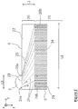
- a heat exchanger 1 of the plate and fin type comprises a stack of plates 2 which extend in two dimensions, length and width, respectively according to the longitudinal direction z and lateral direction y.
- the plates 2 are arranged parallel one above the other with spacing and thus form several sets of passages 3, 4, 5 for fluids F1, F2, F3 to be put into indirect heat exchange relation via the plates 2.
- the lateral direction y is orthogonal to the longitudinal direction z and parallel to the plates 2.
- the longitudinal axis is vertical when the exchanger 1 is in operation.
- each passage has a parallelepipedal and flat shape.
- the passages extend in length in the longitudinal direction z and in width in the lateral direction y.
- the gap between two successive plates is small compared to the length and width of each successive plate.
- Each passage 3, 4, 5 is divided, along the longitudinal direction z, into at least one distribution zone 20 and one heat exchange zone 21.
- the flow of fluids within the distribution zones takes place generally parallel to the longitudinal direction z.
- the heat distribution and exchange zones 20, 21 are preferably juxtaposed along the longitudinal axis z.
- two distribution zones 20 are arranged on either side of the heat exchange zone 21, one serving to bring the fluid F1 to the heat exchange zone 21, the other to be evacuated from said zone.
- Conventional distribution waves produced in the form of corrugated products are shown in distribution zones 20.
- the exchanger 1 comprises collectors of semi-tubular shape 7, 9 provided with openings 10 for the introduction of fluids into the exchanger 1 and the evacuation of the fluids out of the exchanger 1. These collectors have openings that are narrower than the passages.
- the distribution zones 20 serve to distribute the fluids introduced through the openings of the manifolds over the entire width of the passages.
- a distribution element is arranged in at least one distribution zone 20 of a passage 3 of the exchanger, this element comprising a plurality of separating walls 25 arranged so as to dividing said distribution zone 20 into a plurality of channels 26 for the flow of the fluid F1.
- Said channels 26 define flow paths of different lengths and have variable fluid passage sections along said flow paths.
- the distribution element gives structural rigidity to the distribution zone of the exchanger since the spacer function can be provided by the dividing walls.
- the exchanger is of the brazed plate and fin type, that is to say that the separate elements constituting the exchanger are joined together, directly or indirectly by brazing.
- the distribution element according to the invention is distinct from the plates 2.
- brazed support is meant that the support is bonded or secured by brazing with an adjacent plate of the exchanger via at least a portion of their respective surfaces.
- fluid passage section is understood to mean the surface through which the fluid flows within the channel, the latter being measured in a plane perpendicular to the direction of movement of the fluid F1 in said channel, i. e. perpendicular to the current lines of the fluid F1 in motion.
- the length of the flow paths means the distance to be traveled for the fluid F1 between the inlet and the outlet of the channel considered.
- the distribution element further comprises a support 27 configured to hold the walls 25 integral with one another.
- a support 27 configured to hold the walls 25 integral with one another. An example of such an element is shown on the Figure 5B .
- the distribution element is not a corrugated product as is the case with distribution waves conventionally arranged in the distribution zones of a brazed plate and fin heat exchanger.
- the walls 25 are made integral with one another via the same support 27, which confers greater rigidity on the distribution element. This also makes it possible to simplify the brazing operations. In addition, such a configuration offers greater freedom of construction of the distribution element and of the geometry of its channels.
- walls 25 of a relatively large height in the passages typically at least 2 mm, preferably at least 5 mm, more preferably up to 15 mm, or even more, which is not necessary. not the case with exchangers in which the walls result from stamping of the separator plates.
- said support comprises a bottom 27, preferably a flat bottom which can be formed from a flat sheet, from which the dividing walls 25 are erected.
- the walls 25 are preferably erected in the vertical direction x.
- the walls 25 can have heights h typically between 2 and 15 mm. Preferably, the heights are chosen so that the walls 25 extend in almost all, if not all, of the height of the passage in the vertical direction x.
- the configuration of the distribution element 22 according to the invention in which the distribution element is a separate part from the plates, also makes it possible to design separate distribution profiles on either side of the same plate.
- a distribution element according to the invention is housed in several, or even all, of the distribution zones of one or more sets of passages of the exchanger. Said element extends over almost all, or even all, of the height of the passages, measured along the vertical direction x, so that the structure is advantageously in contact with each plate 2 forming the passage 20.
- the channels are preferably fluidly isolated from each other.
- the flow parameters of each channel are thus controlled independently of those of neighboring channels, which makes it possible to adjust specifies the distribution of the fluid over the width of the passages at the outlet of the distribution zone.
- the dividing walls 25 are erected perpendicular to the plates 2.
- the number of channels 26 is at least 6, more preferably between 5 and 50. Indeed, the number of channels 26 must, on the one hand, be sufficient to give the element 22 its rigidity. mechanical and, on the other hand, not to be excessive in order to leave free a sufficient volume for the flow of the fluid and to limit the pressure drops.
- the distribution element 22 comprises a first end 23 forming an inlet or an outlet for the fluid F1 and a second end 24 in fluid communication with the heat exchange zone 21.
- the passages 3 to 5 are bordered by closing bars 6 which do not completely block the passages but leave free openings 23, 24 for the entry or exit of the corresponding fluids.
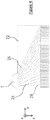
- the Figure 2 partially schematizes the “inlet” part of a passage 3 of an exchanger according to one embodiment of the invention.
- a fluid manifold 7 is arranged in the left corner of the exchanger, the first end 23 being fluidly connected to the manifold 7 and forming an inlet for the fluid F1, the flow of which is shown schematically by dotted arrows.
- the first and second ends 23, 24 preferably extend in a plane parallel to the lateral direction y and perpendicular to the longitudinal direction z.
- the dividing walls 25 extend between the first and second ends 23, 24 and form channels 26 opening out at the level of the second end 24 and configured to uniformly distribute, in the lateral direction y, the fluid F1 so as to obtain a distribution homogeneous or almost homogeneous towards or from the entire width of the heat exchange zone 21 when the other of said first and second ends 23, 24 is supplied with fluid F1.
- each channel is provided with first openings 26a and second openings 26b.
- the first and second openings 26a, 26b are located at the first and second ends 23, 24 respectively, the walls separators 25 extending continuously from the first end 23 to the second end 24.
- the flow path of the fluid F1 corresponds to the path to be traversed between the openings 26a and 26b.
- Each of the ends 23, 24 can thus be divided into a series of openings 26a and a series of openings 26b respectively.
- the openings 26a, 26b of the channels 26 may have identical or variable fluid passage sections depending on the channels 26 considered.
- the fluid passage sections of the openings 26a and 26b correspond to the internal surfaces of the channels 26 measured at the first and second ends 23, 24 in a plane parallel to the lateral direction y.
- At least one first opening 26a has a fluid passage section different from the fluid passage section of another first opening 26a and / or at least one second opening 26b has a fluid passage section different from the one. fluid passage section of another second opening 26b.
- first openings 26a and / or the second openings 26b of the same channel 26 have fluid passage sections that are all the larger as the flow path defined by said channel 26 is long, i. e. that the distance to be traveled for the fluid F1 between the first opening 26a and the second opening 26b is large.
- the first end 23 is subdivided into a first series of first openings 26a having increasing fluid passage sections along the y direction.
- lateral direction y This promotes the supply of the channels configured to distribute the fluid F1 from the manifold 7 to the part of the second end 23 diagonally opposite to said end edge.
- the first openings 26a arranged, preferably symmetrically, on either side of the plane M have sections of fluid passage increasing as one moves away from said median plane M.
- the first end 23 is located on the side of the inlet manifold 7 of the exchanger and forms an inlet for the fluid F1.
- the first openings 26a of the first end 23 have variable fluid passage sections depending on their position along the lateral direction y.
- openings 26a of different passage sections Thanks to the use of openings 26a of different passage sections, it is in particular possible to supercharge channels less conducive to the passage of the fluid, and this as soon as the fluid F1 enters the distribution zone 20, which generates less pressure drops and therefore leads to a more efficient fluid distribution system.
- all or part of the channels 26 comprise means 28 for modifying the linear resistance to flow of said channels 26.
- the linear resistance to flow of each channel can thus be adjusted according to the desired flow characteristics in each channel 26, in particular fluid flow rate and velocity.
- the linear resistance to flow of the channels can be adjusted so that each channel 26 has a similar overall resistance to flow.
- the characteristics of the fluid leaving the channels 26 are thus homogenized in the lateral direction y, which allows uniform distribution towards or from the heat exchange zone 21.
- resistance to flow is understood to mean the capacity of the channel to generate, on the one hand, viscous friction and, on the other hand, to deflect the flow (pressure force normal to the wall).
- This resistance is expressed in the form of a reaction force of the solid structure on the flow in Newtons, which results in the fluid by a pressure drop in Pascals. This force depends on the first order of the kinetic energy of the fluid (rho * u 2 ) and on the second order of the Reynolds number (rho * u * D / mu).
- Linear flow resistance corresponds to the resistance to flow of the channel expressed per unit length.
- a channel 26 will include modification means 28 configured to produce an increase in the linear resistance to flow that is all the greater as the opening 26a of said channel is close, in terms of the distance to be traveled for the fluid F1, of the other opening 26b.
- the channels 26 comprise modifying means 28 configured to produce an increase in the linear resistance to the flow which decreases and decreases in the lateral direction y. Indeed, this makes it possible to compensate for the natural preferential passage of the fluid in the axis rather than by the side of the exchanger, and therefore to obtain a good distribution of the fluid.
- the collector 7 is centered with respect to the median plane M of the exchanger, as shown in Figure 5A , the fluid resistance of a channel will be all the greater the closer it is to the median plane M.
- the channels 26 may have internal profiles shaped to produce different variations in flow resistance.
- Obstacles 28 producing different resistance to flow can also be arranged within one or more channels 26.
- the insertion of a porous structure 28, for example a metal foam, within a channel will make it possible to increase its resistance to flow. It will thus be possible to adjust the linear resistance to the flow of the channels 26, by varying the characteristics of the structures 28 inserted, such as volume, density, etc. depending on the channels. In the example shown on Figure 3B , the volume occupied by the porous structures 28 decreases along the lateral direction y, so as to produce smaller variations in linear resistance to flow along y.
- partitions 28 can be arranged in one or more channels 26 so as to create an additional division stage of the distribution zone 22. This makes it possible to vary the linear resistance to flow as well as to control the parameters even more finely. flow of the fluid distributed to or recovered from the heat exchange zone 21.
- the use of additional partitions 28 is particularly advantageous when the first end 23 of the distribution element has too small a width to be able to be divided into a sufficient number of channels 26.
- the dividing walls 25 and / or the partitions 28 may have, in longitudinal section, rectilinear profiles, as illustrated in the figures.
- the dividing walls 25 have predetermined curvilinear profiles comprising at least one inflection point P.
- Such a geometry makes it possible to deflect the fluid more quickly, that is to say over a shorter distance L1, and this over a large width of the passage of the exchanger. It is thus possible to reduce the longitudinal extent of the distribution zone 20, and consequently to increase the mechanical strength of the exchanger since the compactness of the so-called “weak” zone of the exchanger is increased.
- the first end 23 forming the inlet or outlet of the distribution element 22 has, along the lateral direction y, a width L3 of between 50 and 1000 mm, more preferably of between 100 and 500 mm.
- the distribution element 22 has, parallel to the longitudinal direction z, a length L1 of less than 500 mm, preferably between 50 and 200 mm, more preferably between 80 and 100 mm.
- the length L1 of the distribution element 22 represents less than 20% of the length of the exchange zone 21.
- the distribution element 22 has, parallel to the lateral direction y, a width L2, the ratio between a length L1 and the width L2 being less than 20%, preferably between 5 and 10%.
- the width L2 is preferably between 500 and 1500 mm.
- the distribution element 22 is advantageously formed of a metallic material, preferably aluminum or an aluminum alloy.
- the element can be formed in particular of a porous material, preferably with non-opening pores, for example a metallic foam.
- the distribution element 22 is monolithic, which makes it possible to minimize accidents along the fluid flow paths.
- the element 22 can be manufactured by an additive manufacturing method, preferably by thermal spraying, which makes it possible to produce parts of complex geometries as a single block.
- thermal spraying preferably by thermal spraying
- a so-called “ cold spray” cold spraying process can be used.
- additive manufacturing process can also be designated by the terms “3D printing” or “three-dimensional printing”.
- Additive manufacturing makes it possible to produce a real object, using a specific printer that deposits and / or solidifies material, layer by layer, to obtain the final part. Stacking these layers creates a volume.
- the distribution element 22 can be manufactured by a foundry. This manufacturing process makes it possible to produce parts with complex geometries at a relatively low cost compared to additive manufacturing.
- the element 22 is formed from an aluminum alloy for foundry, that is to say an alloy whose main constituent is aluminum, of lower density than intended to be transformed by techniques of foundry.
- these advantageously comprise heat exchange structures 8 arranged between the plates 2, as shown in FIG. Figure 1 .
- These structures have the function of increasing the heat exchange surface area of the exchanger. and play the role of spacers between the plates 2, in particular during assembly by brazing the exchanger, to prevent any deformation of the plates during the use of fluids under pressure.
- these structures comprise heat exchange waves 8 which advantageously extend along the width and the length of the passages of the exchanger, parallel to the plates 2.
- These waves 8 can be formed in the form of corrugated sheets.
- the wave legs which connect the successive vertices and bases of the wave are called “fins”.
- the exchange structures 8 can also take other particular shapes defined according to the desired fluid flow characteristics. More generally, the term "fins" covers blades or other secondary heat exchange surfaces, which extend from the primary heat exchange surfaces, that is to say the plates of the exchanger, in the passages of the exchanger.
- the distribution element 22 according to the invention and the heat exchange structure 8 are preferably juxtaposed along the longitudinal axis z, that is to say positioned end to end. It being noted that a small clearance may exist between these elements, in order not to block the channels of the exchange zone 21 which are opposite the walls 25 of the channels of the distribution zone 22.
- the first end 23 of element 22 is arranged end-to-end with at least part of manifold 7 while second end 24 is arranged end-to-end with at least part of structure 8.
- structure 8 , the collector 7 and / or the element 22 are linked by brazing to the plates 2 and are linked indirectly to each other via their respective links with the plates 2.
- the element 22 is assembled to the plates 2 by brazing the support 27 to the plates.
- plates 2, the support or bottom 27 comprising at least one face coated with a brazing agent. This face is positioned facing a plate 2 so as to form a connecting surface with said plate 2.
- the plates 2 have in all or part at least one face coated at least in part with a brazing agent layer.
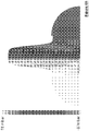
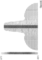
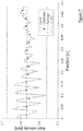
- the results of these simulations are presented on the Figures 6A , 6B , 6C and 7 .
- the Figures 6A , 6B and 6C represent the maps of the speeds, pressures and temperatures of the fluid flowing within the channels 26 of the distribution element 22. There is a quasi-homogeneous distribution of the fluid at the outlet of the channels 26.
- the Figure 7 shows the development of said axial velocity values ( "axial velocity"), that is to say in the longitudinal direction z, obtained at the output of element 22, depending on the position in the lateral direction y. We thus start from the center of the distribution element 22 (position at 0 mm) to the edge of the second end 23 (position at 485 mm).
- the distribution of the speed values along the lateral direction y is characterized by a standard deviation (or standard deviation) of 0.9% and a maximum deviation of 2.8% from the mean value of the speed in the zone d 'exchange, which is much lower than the variations observed with conventional distribution elements for which the standard deviations are of the order of 3%. Thanks to the invention, the variations in speed are therefore reduced in the lateral direction at the outlet of the distribution zone, which makes it possible to distribute the fluid as homogeneously as possible over the entire width of the heat exchange zone. heat.
- a distribution element according to the invention can thus be arranged in any distribution zone of the exchanger, in one or more series of passages 3, 4, 5 of the exchanger, upstream and / or downstream of one or more several of the heat exchanger manifolds.
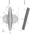
- FIG. 5B illustrates the case where an exchanger passage comprises two distribution elements according to the invention arranged on either side of the heat exchange zone 21 (shown diagrammatically with a deliberately shortened length). It should also be noted that passages 3, 4, 5 of the exchanger can equally well be formed between two successive plates 2 or between a closing bar 6 of the exchanger and an immediately adjacent plate 2.
Description
La présente invention concerne un élément de distribution configuré pour être agencé dans une zone de distribution d'un échangeur de chaleur du type à plaques et ailettes, ainsi qu'un échangeur comprenant un tel élément de distribution et au moins un ensemble de passages pour un fluide à mettre en relation d'échange thermique avec au moins un autre fluide. L'élément selon l'invention permet une répartition plus homogène du fluide sur la largeur desdits passages.The present invention relates to a distribution element configured to be arranged in a distribution zone of a plate and fin type heat exchanger, as well as to an exchanger comprising such a distribution element and at least one set of passages for a heat exchanger. fluid to be placed in a heat exchange relationship with at least one other fluid. The element according to the invention allows a more homogeneous distribution of the fluid over the width of said passages.
La présente invention trouve notamment application dans le domaine de la séparation de gaz par cryogénie, en particulier de la séparation d'air par cryogénie (connue sous l'acronyme anglais « ASU » pour unité de séparation d'air) exploitée pour la production d'oxygène gazeux sous pression. En particulier, la présente invention peut s'appliquer à un échangeur de chaleur qui vaporise un débit liquide, par exemple de l'oxygène, de l'azote et/ou de l'argon par échange de chaleur avec un gaz.The present invention finds particular application in the field of gas separation by cryogenics, in particular air separation by cryogenics (known by the acronym "ASU" for air separation unit) used for the production of gaseous oxygen under pressure. In particular, the present invention can be applied to a heat exchanger which vaporizes a liquid flow, for example oxygen, nitrogen and / or argon by heat exchange with a gas.
La présente invention peut également s'appliquer à un échangeur de chaleur qui vaporise au moins un débit de mélange liquide-gaz, en particulier un débit de mélange à plusieurs constituants, par exemple un mélange d'hydrocarbures, par échange de chaleur avec au moins un autre fluide, par exemple du gaz naturel.The present invention can also be applied to a heat exchanger which vaporizes at least one flow of liquid-gas mixture, in particular a flow of mixture with several constituents, for example a mixture of hydrocarbons, by heat exchange with at least another fluid, for example natural gas.
La technologie couramment utilisée pour un échangeur est celle des échangeurs en aluminium à plaques et à ailettes brasés, qui permettent d'obtenir des dispositifs très compacts offrant une grande surface d'échange.The technology commonly used for an exchanger is that of brazed aluminum plate and fin exchangers, which make it possible to obtain very compact devices offering a large exchange surface.
Ces échangeurs comprennent des plaques entre lesquelles sont insérées des ondes d'échange thermique, formées d'une succession d'ailettes ou jambes d'onde, constituant ainsi un empilage de passages pour les différents fluides à mettre en relation d'échange thermique.These exchangers comprise plates between which are inserted heat exchange waves, formed of a succession of fins or wave legs, thus constituting a stack of passages for the various fluids to be placed in a heat exchange relationship.
Ces passages comprennent des zones dites de distribution agencées, en suivant la direction globale d'écoulement du fluide dans le passage considéré, en amont et en aval de la zone d'échange thermique proprement dite. Les zones de distribution sont reliées fluidiquement à des collecteurs semi-tubulaires configurés pour distribuer les différents fluides sélectivement dans les différents passages, ainsi que pour évacuer lesdits fluides desdits passages.These passages include so-called distribution zones arranged, following the overall direction of flow of the fluid in the passage considered, upstream and downstream of the heat exchange zone proper. The distribution areas are fluidly connected to collectors semi-tubulars configured to distribute the different fluids selectively in the different passages, as well as to evacuate said fluids from said passages.
De façon connue, ces zones de distribution comprennent généralement des ondes de distribution, agencées sous forme de tôles ondulées entre deux plaques successives. Les ondes de distribution sont généralement des ondes droites perforées découpées en forme de triangles ou de trapèzes. Elles assurent la déviation du fluide provenant du collecteur d'entrée de l'échangeur afin de le répartir sur la largeur des zones d'échange thermique, ainsi que la récupération du fluide provenant de ladite zone d'échange thermique. Les ondes de distribution jouent également le rôle d'entretoises pour assurer la tenue mécanique au brasage et en fonctionnement de la zone de distribution du passage. De telles ondes de distribution sont connues des documents
Un des problèmes qui se posent avec la configuration des zones de distribution actuelles est la mal-distribution des fluides en direction en direction des zones d'échange thermique. En effet, les zones de distribution sont occupées par au moins deux tapis d'ondes afin d'optimiser les chutes des découpes de forme, augmentant ainsi le risque de jeu entre les tapis. L'assemblage des tapis d'onde peut aussi occasionner des accidents le long de la voie d'acoulement du fluide, ce qui contribue à augmenter les pertes de charges des zones de distribution. Du fait de ces imperfections des zones de distribution, il peut se produire des variations de débit d'une amplitude de l'ordre de 10%, nuisibles au bon fonctionnement de l'échangeur.One of the problems that arise with the configuration of the current distribution zones is the poor distribution of fluids in the direction of the heat exchange zones. Indeed, the distribution zones are occupied by at least two wave mats in order to optimize the falls of the shaped cutouts, thus increasing the risk of play between the mats. The assembly of the wave mats can also cause accidents along the fluid flow path, which contributes to increasing the pressure drops of the distribution zones. As a result of these imperfections in the distribution zones, variations in flow rate of an amplitude of the order of 10% may occur, which are harmful to the correct operation of the exchanger.
De même, on observe des défauts de distribution dans les zones de distributions dédiées à la récupération des fluides provenant des zones d'échange thermique.Likewise, distribution faults are observed in the distribution zones dedicated to the recovery of fluids coming from the heat exchange zones.
Un autre problème concerne la tenue mécanique des zones de distribution. En effet, ces zones sont munies d'ondes de plus faible densités, typiquement entre 6 et 10 jambes par pouce, que celles des zones d'échange thermique. A l'heure actuelle, la zone de distribution d'un passage s'étend typiquement sur une longueur, mesurée selon une direction longitudinale correspondant à la direction d'écoulement du fluide dans la zone d'échange de chaleur du même passage, de l'ordre de 200 à 600 mm, et sur une largeur, mesurée perpendiculairement à ladite direction longitudinale, de l'ordre de 500 à 1500 mm. Les zones de distribution constituant des parties de moins bonne tenue mécanique que les zones d'échange de chaleur, il est souhaitable de limiter le plus possible leur étendue longitudinale pour garantir une meilleure résistance de l'échangeur lors de la circulation de fluides à haute pression au sein des passages.Another problem relates to the mechanical strength of the distribution zones. Indeed, these zones are provided with waves of lower densities, typically between 6 and 10 legs per inch, than those of the heat exchange zones. At present, the distribution area of a passage extends typically over a length, measured in a longitudinal direction corresponding to the direction of flow of the fluid in the heat exchange zone of the same passage, of the order of 200 to 600 mm, and over a width, measured perpendicular to said longitudinal direction, of the order of 500 to 1500 mm. The distribution zones constituting parts of less good mechanical strength than the heat exchange zones, it is desirable to limit their longitudinal extent as much as possible to guarantee better resistance of the exchanger during the circulation of fluids at high pressure. within the passages.
La présente invention a pour but de résoudre en tout ou partie les problèmes mentionnés ci-avant, notamment de proposer un échangeur de chaleur dans lequel la répartition du ou des fluides dans les zones d'échange de chaleur est la plus uniforme possible, et qui présente en outre des zones de distribution d'encombrement plus faible que dans l'art antérieur.The object of the present invention is to resolve all or part of the above-mentioned problems, in particular to provide a heat exchanger in which the distribution of the fluid (s) in the heat exchange zones is as uniform as possible, and which moreover has distribution zones of smaller bulk than in the prior art.
La solution selon l'invention est alors un échangeur de chaleur du type à plaques et ailettes brasé comprenant :
- une pluralité de plaques agencées parallèlement entre elles de façon à définir au moins un ensemble de passages pour l'écoulement d'un fluide destiné à échanger de la chaleur avec au moins un autre fluide, les passages s'étendant suivant une direction longitudinale et une direction latérale perpendiculaire à ladite direction longitudinale,
- chaque passage étant divisé, suivant la direction longitudinale, en au moins une zone de distribution et une zone d'échange de chaleur,
- au moins une zone de distribution d'un passage comprenant un élément de distribution, ledit élément de distribution comprenant une pluralité de parois séparatrices agencées de manière à diviser ladite zone de distribution en une pluralité de canaux pour l'écoulement du fluide, lesdits canaux définissant des trajets d'écoulement de longueurs différentes et présentant des sections de passage de fluide variables le long desdits trajets d'écoulement, dans lequel les parois séparatrices de l'élément de distribution sont solidarisées entre elles par l'intermédiaire d'un support, ledit support étant brasé avec une plaque adjacente.
- a plurality of plates arranged parallel to each other so as to define at least one set of passages for the flow of a fluid intended to exchange heat with at least one other fluid, the passages extending in a longitudinal direction and a lateral direction perpendicular to said longitudinal direction,
- each passage being divided, along the longitudinal direction, into at least one distribution zone and one heat exchange zone,
- at least one distribution zone of a passage comprising a distribution element, said distribution element comprising a plurality of dividing walls arranged so as to divide said distribution zone into a plurality of channels for the flow of the fluid, said channels defining flow paths of different lengths and having variable fluid passage sections along said flow paths, in which the dividing walls of the distribution element are secured to each other by means of a support, said support being brazed with an adjacent plate.
Selon le cas, l'élément de l'invention peut comprendre l'une ou plusieurs des caractéristiques techniques suivantes :
- les parois séparatrices se projettent depuis le support dans le passage.
- le support comprend un fond plan, les parois séparatrices se projetant perpendiculairement au fond.
- l'élément comprend une première extrémité formant une entrée ou une sortie pour le fluide et une deuxième extrémité en communication fluidique avec la zone d'échange de chaleur lorsque l'élément de distribution est agencé dans une zone de distribution, chaque paroi séparatrice étant formée d'une même pièce et s'étendant de façon continue depuis la première extrémité jusqu'à la deuxième extrémité.
- chaque canal est muni d'une première ouverture et d'une deuxième ouverture se situant au niveau des première et deuxième extrémités respectivement.
- au moins une première ouverture présente une section de passage de fluide différente de la section de passage de fluide d'une autre première ouverture et/ou au moins une deuxième ouverture présente une section de passage de fluide différente de la section de passage de fluide d'une autre deuxième ouverture.
- les premières ouvertures et/ou les deuxièmes ouvertures d'un même canal présentent des sections de passage de fluide d'autant plus grandes que le trajet d'écoulement défini par ledit canal est long.
- un ou plusieurs canaux comprennent des moyens de modification de la résistance linéique à l'écoulement desdits canaux.
- lesdits moyens comprennent une conformation des profils intérieurs desdits canaux.
- lesdits moyens comprennent des cloisons agencées au sein desdits canaux.
- lesdits moyens comprennent des structures poreuses, par exemple des mousses métalliques, agencées au sein desdits canaux.
- les parois séparatrices présentent, en coupe longitudinale, des profils rectilignes.
- les parois séparatrices présentent, en coupe longitudinale, des profils curvilignes prédéterminés.
- lesdits profils curvilignes prédéterminés comprennent au moins un point d'inflexion.
- l'élément de distribution s'étend sur une longueur suivant une direction longitudinale et sur une largeur suivant une direction latérale, le rapport entre une longueur et la largeur étant inférieur à 20%, de préférence compris entre 5 et 10%.
- l'élément de distribution s'étend sur une longueur inférieure à 500 mm, de préférence comprise entre 50 et 200 mm.
- l'élément de distribution présente une hauteur, mesurée suivant une direction verticale orthogonale aux plaques, d'au moins 2 mm, de préférence au moins 5 mm, de préférence une hauteur comprise entre 2 et 15 mm.
- l'élément de distribution est un élément monolithique, de préférence fabriqué par une méthode de fabrication additive ou par fonderie.
- the dividing walls project from the support into the passage.
- the support comprises a flat bottom, the dividing walls projecting perpendicularly to the bottom.
- the element comprises a first end forming an inlet or an outlet for the fluid and a second end in fluid communication with the heat exchange zone when the distribution element is arranged in a distribution zone, each dividing wall being formed in one piece and extending continuously from the first end to the second end.
- each channel is provided with a first opening and a second opening located at the first and second ends respectively.
- at least one first opening has a fluid passage section different from the fluid passage section of another first opening and / or at least one second opening has a fluid passage section different from the fluid passage section d 'another second opening.
- the first openings and / or the second openings of the same channel have fluid passage sections that are all the larger as the flow path defined by said channel is long.
- one or more channels include means for modifying the linear resistance to flow of said channels.
- said means comprise a conformation of the interior profiles of said channels.
- said means comprise partitions arranged within said channels.
- said means comprise porous structures, for example metallic foams, arranged within said channels.
- the dividing walls have, in longitudinal section, rectilinear profiles.
- the dividing walls have, in longitudinal section, predetermined curvilinear profiles.
- said predetermined curvilinear profiles include at least one inflection point.
- the distribution element extends over a length in a longitudinal direction and over a width in a lateral direction, the ratio between a length and the width being less than 20%, preferably between 5 and 10%.
- the distribution element extends over a length of less than 500 mm, preferably between 50 and 200 mm.
- the distribution element has a height, measured in a vertical direction orthogonal to the plates, of at least 2 mm, preferably at least 5 mm, preferably a height of between 2 and 15 mm.
- the distribution element is a monolithic element, preferably manufactured by an additive manufacturing method or by a foundry.
La présente invention va maintenant être mieux comprise grâce à la description qui va suivre, donnée uniquement à titre d'exemple non limitatif et faite en référence aux schémas ci-annexés, parmi lesquels :
- la
Figure 1 est une vue schématique tridimensionnelle d'un échangeur du type à plaque et ailettes ; - la
Figure 2 est une vue schématique partielle, en coupe longitudinale d'une zone de distribution selon un mode de réalisation de l'invention ; - les
Figures 3A, 3B et4 sont des vues schématiques partielles, en coupe longitudinale de zones de distribution selon d'autres modes de réalisation de l'invention ; - les
Figures 5A et 5B sont des vues schématiques, en coupe longitudinale et tridimensionnelle respectivement, d'une zone de distribution selon un autre mode de réalisation de l'invention ; - les
Figures 6A ,6B ,6C et7 présentent des résultats de simulations réalisées avec un élément de distribution telle que schématisé sur laFigure 5B .
- the
Figure 1 is a three-dimensional schematic view of a plate and fin type heat exchanger; - the
Figure 2 is a partial schematic view, in longitudinal section of a distribution zone according to one embodiment of the invention; - the
Figures 3A, 3B and4 are partial schematic views, in longitudinal section of distribution zones according to other embodiments of the invention; - the
Figures 5A and 5B are schematic views, in longitudinal and three-dimensional section respectively, of a distribution zone according to another embodiment of the invention; - the
Figures 6A ,6B ,6C and7 present the results of simulations carried out with a distribution element as shown schematically on theFigure 5B .
Comme on le voit sur la
De préférence, chaque passage a une forme parallélépipédique et plate. Les passages s'étendent en longueur suivant la direction longitudinale z et en largeur suivant la direction latérale y. L'écart entre deux plaques successives est petit devant la longueur et la largeur de chaque plaque successive.Preferably, each passage has a parallelepipedal and flat shape. The passages extend in length in the longitudinal direction z and in width in the lateral direction y. The gap between two successive plates is small compared to the length and width of each successive plate.
Chaque passage 3, 4, 5 est divisé, suivant la direction longitudinale z, en au moins une zone de distribution 20 et une zone d'échange de chaleur 21. L'écoulement des fluides au sein des zones de distribution a lieu globalement parallèlement à la direction longitudinale z. Les zones de distribution et d'échange de chaleur 20, 21 sont de préférence juxtaposées le long de l'axe longitudinal z.Each passage 3, 4, 5 is divided, along the longitudinal direction z, into at least one
Selon la représentation de la
De façon connue en soi, l'échangeur 1 comprend des collecteurs de forme semi-tubulaire 7, 9 munis d'ouvertures 10 pour l'introduction des fluides dans l'échangeur 1 et l'évacuation des fluides hors de l'échangeur 1. Ces collecteurs présentent des ouvertures moins large que les passages. Les zones de distribution 20 servent à répartir les fluides introduits par les ouvertures des collecteurs sur toute la largeur des passages.In a manner known per se, the
Selon l'invention, on agence un élément de distribution dans au moins une zone de distribution 20 d'un passage 3 de l'échangeur, cet élément comprenant une pluralité de parois séparatrices 25 agencées de manière à diviser ladite zone de distribution 20 en une pluralité de canaux 26 pour l'écoulement du fluide F1. Lesdits canaux 26 définissent des trajets d'écoulement de longueurs différentes et présentent des sections de passage de fluide variables le long desdits trajet d'écoulement. Le fait de subdiviser la zone de distribution en plusieurs canaux distincts de longueurs et de sections variables permet de dévier le fluide tout en contrôlant finement les conditions d'écoulement du fluide au sein de chaque canal. En particulier, il est possible de rééquilibrer les vitesses du fluide s'écoulant dans les différents canaux, de manière à obtenir des vitesses de fluide sensiblement identiques en sortie de chaque canal, et de là une répartition uniforme ou quasi-uniforme du fluide sur la largeur des passages en sortie de la zone de distribution, tout en minimisant les pertes de charge de la zone de distribution.According to the invention, a distribution element is arranged in at least one
De plus, l'élément de distribution confère une rigidité structurelle à la zone de distribution de l'échangeur puisque la fonction d'entretoise peut être assurée par les parois séparatrices.In addition, the distribution element gives structural rigidity to the distribution zone of the exchanger since the spacer function can be provided by the dividing walls.
A noter que dans le cadre de l'invention, l'échangeur est du type à plaques et ailettes brasé, c'est-à-dire que les éléments distincts constituant l'échangeurs sont solidarisés, directement ou indirectement par brasage. L'élément de distribution selon l'invention est distinct des plaques 2.It should be noted that in the context of the invention, the exchanger is of the brazed plate and fin type, that is to say that the separate elements constituting the exchanger are joined together, directly or indirectly by brazing. The distribution element according to the invention is distinct from the plates 2.
Par « support brasé », on entend que le support est lié ou solidarisé par brasage avec une plaque adjacente de l'échangeur via au moins une portion de leurs surfaces respective.By “brazed support” is meant that the support is bonded or secured by brazing with an adjacent plate of the exchanger via at least a portion of their respective surfaces.
A noter que par « section de passage de fluide », on entend la surface à travers laquelle le fluide s'écoule au sein du canal, celle-ci étant mesurée dans un plan perpendiculaire à la direction de déplacement du fluide F1 dans ledit canal, i. e. perpendiculaire aux lignes de courant du fluide F1 en mouvement.Note that the term “fluid passage section” is understood to mean the surface through which the fluid flows within the channel, the latter being measured in a plane perpendicular to the direction of movement of the fluid F1 in said channel, i. e. perpendicular to the current lines of the fluid F1 in motion.
La longueur des trajets d'écoulement s'entend de la distance à parcourir pour le fluide F1 entre l'entrée et la sortie du canal considéré.The length of the flow paths means the distance to be traveled for the fluid F1 between the inlet and the outlet of the channel considered.
Selon l'invention, l'élément de distribution comprend en outre un support 27 configuré pour maintenir les parois 25 solidaires entre elles. Un exemple d'un tel élément est présenté sur la
On comprend alors que l'élément de distribution n'est pas un produit ondulé comme c'est le cas avec les ondes de distribution classiquement disposées dans les zones de distribution d'un échangeur à plaques et ailettes brasé. Les parois 25 sont solidarisées entre elles via un même support 27, ce qui confère une plus grande rigidité à l'élément de distribution. Cela permet en outre de simplifier les opérations de brasage. En outre, une telle configuration offre une plus grande liberté de construction de l'élément de distribution et de géométrie de ses canaux.It will then be understood that the distribution element is not a corrugated product as is the case with distribution waves conventionally arranged in the distribution zones of a brazed plate and fin heat exchanger. The
Ainsi, il est possible de disposer des parois 25 d'une hauteur relativement importante dans les passages, typiquement au moins 2 mm, de préférence au moins 5 mm, de préférence encore jusqu'à 15 mm, voire plus, ce qui n'est pas le cas avec les échangeurs dans lesquels les parois résultent d'un emboutissage des plaques séparatrices.Thus, it is possible to have
De préférence, ledit support comprend un fond 27, de préférence un fond plan pouvant être formé d'une tôle plane, à partir de laquelle les parois séparatrices 25 sont érigées. Les parois 25 sont érigées de préférence suivant la direction verticale x. Les parois 25 peuvent avoir des hauteurs h typiquement comprises entre 2 et 15 mm. De préférence, les hauteurs sont choisies de sorte que les parois 25 s'étendent dans la quasi-totalité, voire la totalité, de la hauteur du passage selon la direction verticale x.Preferably, said support comprises a bottom 27, preferably a flat bottom which can be formed from a flat sheet, from which the dividing
La configuration de l'élément de distribution 22 selon l'invention, dans laquelle l'élément de distribution est une pièce distincte des plaques, permet également de concevoir des profils de distribution distincts de part et d'autre d'une même plaque.The configuration of the
De préférence, un élément de distribution selon l'invention est logé dans plusieurs, voire la totalité, des zones de distribution d'un ou plusieurs ensembles de passages de l'échangeur. Ledit élément s'étend sur la quasi-totalité, voire la totalité, de la hauteur des passages, mesurée suivant selon la direction verticale x, de sorte que la structure est avantageusement en contact avec chaque plaque 2 formant le passage 20.Preferably, a distribution element according to the invention is housed in several, or even all, of the distribution zones of one or more sets of passages of the exchanger. Said element extends over almost all, or even all, of the height of the passages, measured along the vertical direction x, so that the structure is advantageously in contact with each plate 2 forming the
Les canaux sont de préférence isolés fluidiquement les uns des autres. Les paramètres d'écoulement de chaque canal sont ainsi contrôlés indépendamment de ceux des canaux voisins, ce qui permet d'ajuster de façon précise la distribution du fluide sur la largeur des passages au niveau de la sortie de la zone de distribution. Avantageusement, les parois séparatrices 25 sont érigées perpendiculairement aux plaques 2.The channels are preferably fluidly isolated from each other. The flow parameters of each channel are thus controlled independently of those of neighboring channels, which makes it possible to adjust specifies the distribution of the fluid over the width of the passages at the outlet of the distribution zone. Advantageously, the dividing
De préférence, le nombre de canaux 26 est d'au moins 6, de préférence encore compris entre 5 et 50. En effet, le nombre de canaux 26 doit, d'une part, être suffisant pour conférer à l'élément 22 sa rigidité mécanique et, d'autre part ne pas être excessif afin de laisser libre un volume suffisant pour l'écoulement du fluide et de limiter les pertes de charge.Preferably, the number of
Avantageusement, l'élément de distribution 22 comprend une première extrémité 23 formant une entrée ou une sortie pour le fluide F1 et une deuxième extrémité 24 en communication fluidique avec la zone d'échange de chaleur 21.Advantageously, the
Plus précisément, comme visible sur la
La
Les première et deuxième extrémités 23, 24 s'étendent de préférence dans un plan parallèle à la direction latérale y et perpendiculaire à la direction longitudinale z. Les parois séparatrices 25 s'étendent entre les première et deuxième extrémités 23, 24 et forment des canaux 26 débouchant au niveau de la deuxième extrémité 24 et configurés pour répartir uniformément, suivant la direction latérale y, le fluide F1 de façon à obtenir une distribution homogène ou quasi-homogène vers ou depuis toute la largeur de la zone d'échange de chaleur 21 lorsque l'autre desdites première et deuxième extrémités 23, 24 est alimentée en fluide F1.The first and second ends 23, 24 preferably extend in a plane parallel to the lateral direction y and perpendicular to the longitudinal direction z. The dividing
Avantageusement, chaque canal est muni de premières ouvertures 26a et de deuxièmes ouvertures 26b. Avantageusement, comme schématisé sur la
Les ouvertures 26a, 26b des canaux 26 pourront présenter des sections de passage de fluide identiques ou variables selon les canaux 26 considérés. Les sections de passage de fluide des ouvertures 26a et 26b, correspondent aux surfaces internes des canaux 26 mesurées au niveau des première et deuxième extrémités 23, 24 dans un plan parallèle à la direction latérale y.The
De préférence, au moins une première ouverture 26a présente une section de passage de fluide différente de la section de passage de fluide d'une autre première ouverture 26a et/ou au moins une deuxième ouverture 26b présente une section de passage de fluide différente de la section de passage de fluide d'une autre deuxième ouverture 26b.Preferably, at least one
Avantageusement, les premières ouvertures 26a et/ou les deuxièmes ouvertures 26b d'un même canal 26 présentent des sections de passage de fluide d'autant plus grandes que le trajet d'écoulement défini par ledit canal 26 est long, i. e. que la distance à parcourir pour le fluide F1 entre la première ouverture 26a et la deuxième ouverture 26b est grande.Advantageously, the
Ainsi, dans l'exemple des
Selon un autre exemple (
On compense ainsi la tendance naturelle du fluide à passer dans la région de la zone de distribution située en regard du collecteur plutôt que par les zones plus éloignées du collecteur, et ainsi d'homogénéiser la distribution du fluide dans la largeur du passage 3 de l'échangeur.This compensates for the natural tendency of the fluid to pass through the region of the distribution zone situated opposite the manifold rather than through the zones further away from the manifold, and thus to homogenize the distribution of the fluid in the width of the passage 3 of the manifold. 'interchange.
Avantageusement, lorsque l'élément de distribution 22 est disposé dans la zone de distribution 20 d'un échangeur, la première extrémité 23 se situe du côté du collecteur 7 d'entrée de l'échangeur et forme une entrée pour le fluide F1. Les premières ouvertures 26a de la première extrémité 23 présentent des sections de passage de fluide variables selon leur position le long de la direction latérale y.Advantageously, when the
Grâce à l'utilisation d'ouvertures 26a de sections de passage différentes, il est notamment possible de suralimenter des canaux moins propices au passage du fluide, et ce dès l'entrée du fluide F1 dans la zone de distribution 20, ce qui engendre moins de pertes de charges et conduit donc à un système de distribution de fluide plus performant.Thanks to the use of
Selon un mode avantageux de réalisation de l'invention, tout ou partie des canaux 26 comprennent des moyens 28 de modification de la résistance linéique à l'écoulement desdits canaux 26. La résistance linéique à l'écoulement de chaque canal peut ainsi être ajustée selon les caractéristiques d'écoulement souhaitées dans chaque canal 26, en particulier débit et vitesse de fluide. Ainsi, la résistance linéique à l'écoulement des canaux peut être ajustée de sorte que chaque canal 26 présente une résistance à l'écoulement globale similaire. Les caractéristiques du fluide en sortie des canaux 26 sont ainsi homogénéisées suivant la direction latérale y, ce qui permet une distribution uniforme vers ou depuis la zone d'échange de chaleur 21.According to an advantageous embodiment of the invention, all or part of the
Par « résistance à l'écoulement », on entend la capacité du canal à générer d'une part des frottements visqueux et d'autre part à dévier l'écoulement (force de pression normale à la paroi). Cette résistance s'exprime sous la forme d'une force de réaction de la structure solide sur l'écoulement en Newton, ce qui se traduit dans le fluide par une perte de charge en Pascals. Cette force dépend au premier ordre de l'énergie cinétique du fluide (rho*u2) et au deuxième ordre du nombre de Reynolds (rho*u*D/mu). La résistance à l'écoulement linéique correspond à la résistance à l'écoulement du canal exprimée par unité de longueur.The term “resistance to flow” is understood to mean the capacity of the channel to generate, on the one hand, viscous friction and, on the other hand, to deflect the flow (pressure force normal to the wall). This resistance is expressed in the form of a reaction force of the solid structure on the flow in Newtons, which results in the fluid by a pressure drop in Pascals. This force depends on the first order of the kinetic energy of the fluid (rho * u 2 ) and on the second order of the Reynolds number (rho * u * D / mu). Linear flow resistance corresponds to the resistance to flow of the channel expressed per unit length.
Avantageusement, un canal 26 comprendra des moyens de modification 28 configurés pour produire une augmentation de la résistance linéique à l'écoulement d'autant plus importante que l'ouverture 26a dudit canal est proche, en termes de distance à parcourir pour le fluide F1, de l'autre ouverture 26b. Par exemple, dans la configuration illustrée sur la
Les canaux 26 pourront présenter des profils internes conformés pour produire des variations de résistance à l'écoulement différentes.The
On pourra également agencer au sein d'un ou plusieurs canaux 26 des obstacles 28 produisant des résistances à l'écoulement différentes. L'insertion d'une structure poreuse 28, par exemple une mousse métallique, au sein d'un canal permettra d'augmenter sa résistance à l'écoulement. On pourra ainsi ajuster la résistance linéique à l'écoulement des canaux 26, en faisant varier les caractéristiques des structures 28 insérées, telles que volume, densité, ... selon les canaux. Dans l'exemple illustré sur la
Selon l'exemple schématisé sur la
Selon le cas, les parois séparatrices 25 et/ou les cloisons 28, peuvent présenter, en coupe longitudinale, des profils rectilignes, comme illustré sur lesDepending on the case, the dividing
Selon un mode de réalisation particulièrement avantageux, les parois séparatrices 25 présentent des profils curvilignes prédéterminés comprenant au moins un point d'inflexion P.According to a particularly advantageous embodiment, the dividing
Une telle géométrie permet de dévier le fluide plus rapidement, c'est-à-dire sur une distance L1 plus courte, et ce sur une largeur importante du passage de l'échangeur. Il est ainsi possible de réduire l'étendue longitudinale de la zone de distribution 20, et d'augmenter en conséquence la tenue mécanique de l'échangeur puisque l'on augmente la compacité de la zone dite « faible » de l'échangeur.Such a geometry makes it possible to deflect the fluid more quickly, that is to say over a shorter distance L1, and this over a large width of the passage of the exchanger. It is thus possible to reduce the longitudinal extent of the
Cela offre également la possibilité de réduire la largeur de la première extrémité 23 de l'élément de distribution 22, et donc la largeur du collecteur 7, qui est une pièce relativement coûteuse. De préférence, la première extrémité 23 formant entrée ou sortie de l'élément de distribution 22 présente, suivant la direction latérale y, une largeur L3 comprise entre 50 et 1000 mm, de préférence encore comprise entre 100 et 500 mm.This also offers the possibility of reducing the width of the
De tels profils permettent également de réduire les pertes de charge au sein des canaux 26, les changements brusques de profils de canal étant connus pour générer des recirculations de fluides à l'origine de pertes de charges.Such profiles also make it possible to reduce the pressure drops within the
De préférence, l'élément de distribution 22 présente, parallèlement à la direction longitudinale z, une longueur L1 inférieure à 500 mm, de préférence comprise entre 50 et 200 mm, de préférence encore comprise entre 80 et 100 mm. De préférence, la longueur L1 de l'élément de distribution 22 représente moins de 20% de la longueur de la zone d'échange 21. L'élément de distribution 22 présente, parallèlement à la direction latérale y, une largeur L2, le rapport entre une longueur L1 et la largeur L2 étant inférieur à 20%, de préférence compris entre 5 et 10%. La largeur L2 est de préférence comprise entre 500 et 1500 mm.Preferably, the
L'élément de distribution 22 est avantageusement formé d'un matériau métallique, de préférence de l'aluminium ou un alliage d'aluminium. L'élément peut être formé en particulier d'un matériau poreux, de préférence à pores non débouchants, par exemple une mousse métallique.The
De préférence, l'élément de distribution 22 est monolithique, ce qui permet de minimiser les accidents le long des voies d'écoulement du fluide.Preferably, the
L'élément 22 peut être fabriqué par une méthode de fabrication additive, de préférence par projection thermique, ce qui permet de réaliser d'un seul bloc des pièces de géométries complexes. En particulier, on pourra utiliser un procédé de projection à froid dit « cold spray ». The
A noter que le procédé de fabrication additive peut aussi être désigné par les termes « impression 3D » ou « impression tridimensionnelle ». La fabrication additive permet de produire un objet réel, en utilisant une imprimante spécifique qui dépose et/ou solidifie de la matière, couche par couche, pour obtenir la pièce finale. L'empilement de ces couches permet de créer un volume.Note that the additive manufacturing process can also be designated by the terms “3D printing” or “three-dimensional printing”. Additive manufacturing makes it possible to produce a real object, using a specific printer that deposits and / or solidifies material, layer by layer, to obtain the final part. Stacking these layers creates a volume.
L'élément 22 peut aussi être fabriqué par les procédés de fabrication additive suivants:
- le procédé FDM (acronyme de « Fuse Deposition Modeling »), qui consiste en un modelage par dépôt de matière en fusion),
- la stéréolithographie (SLA), procédé dans lequel un rayonnement ultraviolet solidifie une couche de plastique liquide, ou
- le frittage sélectif par laser, dans lequel un laser agglomère une couche de poudre.
- the FDM process (acronym for “ Fuse Deposition Modeling ”), which consists of modeling by deposition of molten material),
- stereolithography (SLA), a process in which ultraviolet radiation solidifies a layer of liquid plastic, or
- selective laser sintering, in which a laser agglomerates a layer of powder.
De façon alternative, l'élément de distribution 22 peut être fabriqué par fonderie. Ce procédé de fabrication permet de réaliser des pièces de géométries complexes à un coût relativement faible comparé à la fabrication additive. De préférence, l'élément 22 est formé d'un alliage d'aluminium pour fonderie, c'est-à-dire un alliage dont le constituant principal est l'aluminium, de masse volumique inférieure à destiné à être transformé par des techniques de fonderie.Alternatively, the
S'agissant des zones d'échange de chaleur 21 de l'échangeur, celles-ci comprennent avantageusement des structures d'échange thermique 8 disposées entre les plaques 2, comme montré sur la
De préférence, ces structures comprennent des ondes d'échange thermique 8 qui s'étendent avantageusement suivant la largeur et la longueur des passages de l'échangeur, parallélement aux plaques 2. Ces ondes 8 peuvent être formées sous forme de tôles ondulées. Dans ce cas, on appelle « ailettes » les jambes d'onde qui relient les sommets et les bases successifs de l'onde. Les structures d'échange 8 peuvent aussi revêtir d'autres formes particulières définies selon les caractéristiques d'écoulement de fluide souhaitées. De manière plus générale, le terme « ailettes » couvre des lames ou autres surfaces secondaires d'échange thermique, qui s'étendent depuis les surfaces primaires d'échange thermiques, c'est-à-dire les plaques de l'échangeur, dans les passages de l'échangeur.Preferably, these structures comprise heat exchange waves 8 which advantageously extend along the width and the length of the passages of the exchanger, parallel to the plates 2. These waves 8 can be formed in the form of corrugated sheets. In this case, the wave legs which connect the successive vertices and bases of the wave are called “fins”. The exchange structures 8 can also take other particular shapes defined according to the desired fluid flow characteristics. More generally, the term "fins" covers blades or other secondary heat exchange surfaces, which extend from the primary heat exchange surfaces, that is to say the plates of the exchanger, in the passages of the exchanger.
Au sein d'un passage, l'élément de distribution 22 selon l'invention et la structure d'échange thermique 8 sont de préférence juxtaposées le long de l'axe longitudinal z, c'est-à-dire positionnées bout à bout. Etant noté qu'un faible jeu peut exister entre ces éléments, ceci afin de ne pas boucher les canaux de la zone d'échange 21 qui sont en regard des parois 25 des canaux de la zone de distribution 22. De préférence, la première extrémité 23 de l'élément 22 est agencée bout-à-bout avec au moins une partie du collecteur 7 tandis que la deuxième extrémité 24 est agencée bout-à-bout avec au moins une partie de la structure 8. De préférence, la structure 8, le collecteur 7 et/ou l'élément 22 sont liés par brasage aux plaques 2 et sont liés indirectement entre eux via leurs liaisons respectives avec les plaques 2. Avantageusement, l'élément 22 est assemblé aux plaques 2 par brasage du support 27 aux plaques 2, le support ou fond 27 comprenant au moins une face revêtue d'un agent de brasage. Cette face est positionnée en regard d'une plaque 2 de façon à former une surface de liaison avec ladite plaque 2. De façon alternative ou complémentaire, les plaques 2 présentent en tout ou partie au moins une face revêtue au moins en partie d'une couche d'agent de brasage.Within a passage, the
Afin de montrer l'efficacité d'un élément de distribution 22 selon l'invention pour distribuer de façon uniforme le fluide, des simulations d'écoulement de fluide ont été réalisées avec un élément de distribution selon la
Les caractéristiques dimensionnelles de l'élément de distribution 22 étaient les suivantes :
- longueur L1 de l'élément 22 : 85 mm,
- demi-largeur L2/2 de l'élément 22 : 485 mm,
- largeur L3 de la première extrémité 23 formant entrée: 370mm,
- jeu mécanique entre l'élément de
distribution 22 et la structure d'échange thermique 8: 2 mm, - hauteur de l'élément 22: 9,5mm (les parois 25 ayant une hauteur, suivant la direction verticale x de 7,5 mm et lefond 27 ayant une épaisseur de 2 mm),
- épaisseur des parois 25: 2,3 mm.
- length L1 of element 22: 85 mm,
- half-width L2 / 2 of element 22: 485 mm,
- width L3 of the
first end 23 forming an inlet: 370mm, - mechanical clearance between the
distribution element 22 and the heat exchange structure 8: 2 mm, - height of element 22: 9.5mm (the
walls 25 having a height, in the vertical direction x of 7.5 mm and the bottom 27 having a thickness of 2 mm), - wall thickness 25: 2.3 mm.
S'agissant du fluide, les paramètres de simulation étaient les suivants :
- nature du fluide : azote,
- pression du fluide en sortie de l'élément de distribution 22: 1,2 bar,
- température du fluide à l'entrée du collecteur 7: - 80°C,
- température du fluide à la sortie du collecteur 9: 17°C,
- débit massique de fluide circulant dans le passage de l'échangeur: 100kg/h.
- nature of the fluid: nitrogen,
- fluid pressure at the outlet of the distribution element 22: 1.2 bar,
- temperature of the fluid at the inlet of manifold 7: - 80 ° C,
- fluid temperature at the outlet of manifold 9: 17 ° C,
- mass flow rate of fluid circulating in the exchanger passage: 100 kg / h.
Les résultats de ces simulations sont présentés sur les
Bien entendu, l'invention n'est pas limitée aux exemples particuliers décrits et illustrés dans la présente demande. D'autres variantes ou modes de réalisation à la portée de l'homme du métier peuvent aussi être envisagés sans sortir du cadre de l'invention. A titre d'exemple, d'autres directions et sens d'écoulement des fluides dans l'échangeur sont bien entendu envisageables, sans sortir du cadre de la présente invention. Un élément de distribution selon l'invention peut ainsi être agencé dans toute zone de distribution de l'échangeur, dans une ou plusieurs séries de passage 3, 4, 5 de l'échangeur, en amont et/ou en aval d'un ou plusieurs des collecteurs de l'échangeur. Par exemple, la
Claims (17)
- Heat exchanger (1) of the brazed plate and fin type, comprising:- a plurality of plates (2) arranged in a mutually parallel manner so as to define at least one set of passages (3) for a fluid (F1) intended to exchange heat with at least one other fluid (F2) to flow through, the passages (3) extending in a longitudinal direction (z) and a lateral direction (x) perpendicular to said longitudinal direction (z),- each passage (3) being divided, in the longitudinal direction (z), into at least one distribution zone (20) and one heat-exchange zone (21),- at least one distribution zone (20) of a passage (3) comprising a distribution element (22), said distribution element (22) comprising a plurality of dividing walls (25) arranged so as to divide said distribution zone (20) into a plurality of channels (26) for the fluid (F1) to flow through, said channels (26) defining flow paths of different lengths and having variable passage sections for fluid along said flow paths,
wherein the dividing walls (25) of the distribution element (22) are secured together via a support (27), said support (27) being brazed to an adjacent plate (2). - Heat exchanger according to Claim 1, characterized in that the dividing walls (25) project from the support (27) into the passage (3).
- Heat exchanger according to Claim 2, characterized in that the support (27) comprises a flat bottom (27), the dividing walls (25) projecting perpendicularly to the bottom (27).
- Heat exchanger according to one of the preceding claims, characterized in that it comprises a first end (23) forming an inlet or an outlet for the fluid (F1) and a second end (24) fluidically connected to the heat-exchange zone (21) when the distribution element is arranged in a distribution zone (20), each dividing wall (25) being formed from a single part and extending continuously from the first end (23) to the second end (24).
- Heat exchanger according to Claim 4, characterized in that each channel (26) is provided with a first opening (26a) and a second opening (26b) situated at the first and second ends (23, 24), respectively, at least one first opening (26a) having a passage section for fluid that is different than the passage section for fluid of another first opening (26a), and/or at least one second opening (26b) having a passage section for fluid that is different than the passage section for fluid of another second opening (26b).
- Heat exchanger according to Claim 5, characterized in that the first openings (26a) and/or the second openings (26b) of one and the same channel (26) have passage sections for fluid that are larger the longer the flow path defined by said channel (26).
- Heat exchanger according to one of the preceding claims, characterized in that one or more channels (26) comprise means (28) for modifying the linear flow resistance of said channels (26).
- Heat exchanger according to Claim 7, characterized in that said means (28) comprise a shape of the interior profiles of said channels (26).
- Heat exchanger according to either of Claims 7 and 8, characterized in that said means (28) comprise partitions (28) arranged within said channels (26).
- Heat exchanger according to one of Claims 7 to 9, characterized in that said means (28) comprise porous structures, for example metal foams, arranged within said channels (26).
- Heat exchanger according to one of the preceding claims, characterized in that the dividing walls (25) have rectilinear profiles in longitudinal section.
- Heat exchanger according to one of Claims 1 to 10, characterized in that the dividing walls (25) have predetermined curvilinear profiles in longitudinal section.
- Heat exchanger according to Claim 12, characterized in that said predetermined curvilinear profiles comprise at least one inflection point (P).
- Heat exchanger according to one of the preceding claims, characterized in that the distribution element (22) extends along a length (L1) in a longitudinal direction (z) and across a width (L2) in a lateral direction (y), the ratio between a length (L1) and the width (L2) being less than 20%, preferably between 5 and 10%.
- Heat exchanger according to one of the preceding claims, characterized in that the distribution element (22) extends along a length (L1) less than 500 mm, preferably between 50 and 200 mm.
- Heat exchanger according to one of the preceding claims, characterized in that the distribution element (22) has a height, measured in a vertical direction (x) orthogonal to the plates (2), of at least 2 mm, preferably at least 5 mm, preferably a height of between 2 and 15 mm.
- Heat exchanger according to one of the preceding claims, characterized in that the distribution element (22) is a monolithic element, preferably manufactured by an additive manufacturing method or by casting.
Applications Claiming Priority (2)
| Application Number | Priority Date | Filing Date | Title |
|---|---|---|---|
| FR1757539A FR3069918B1 (en) | 2017-08-04 | 2017-08-04 | HEAT EXCHANGER COMPRISING A MULTI-CHANNEL DISTRIBUTION ELEMENT |
| PCT/FR2018/051804 WO2019025691A1 (en) | 2017-08-04 | 2018-07-16 | Heat exchanger comprising a multi-channel distribution element |
Publications (2)
| Publication Number | Publication Date |
|---|---|
| EP3662222A1 EP3662222A1 (en) | 2020-06-10 |
| EP3662222B1 true EP3662222B1 (en) | 2021-05-26 |
Family
ID=60515515
Family Applications (1)
| Application Number | Title | Priority Date | Filing Date |
|---|---|---|---|
| EP18755512.3A Active EP3662222B1 (en) | 2017-08-04 | 2018-07-16 | Heat exchanger with distributing element |
Country Status (6)
| Country | Link |
|---|---|
| US (1) | US20200370836A1 (en) |
| EP (1) | EP3662222B1 (en) |
| JP (1) | JP7150819B2 (en) |
| CN (1) | CN111065879B (en) |
| FR (1) | FR3069918B1 (en) |
| WO (1) | WO2019025691A1 (en) |
Families Citing this family (5)
| Publication number | Priority date | Publication date | Assignee | Title |
|---|---|---|---|---|
| DE102018003479A1 (en) * | 2018-04-27 | 2019-10-31 | Linde Aktiengesellschaft | Plate heat exchanger, process plant and process |
| US11226158B2 (en) * | 2019-04-01 | 2022-01-18 | Hamilton Sundstrand Corporation | Heat exchanger fractal splitter |
| FR3096768B1 (en) * | 2019-05-29 | 2021-04-30 | Air Liquide | Exchanger-reactor with improved distribution zones |
| FR3096767B1 (en) * | 2019-05-31 | 2021-07-30 | Safran | DEFLECTION HEAT EXCHANGER |
| CN113993346B (en) * | 2021-10-20 | 2023-01-17 | 联想(北京)有限公司 | Air guide device and method for manufacturing air guide device |
Family Cites Families (14)
| Publication number | Priority date | Publication date | Assignee | Title |
|---|---|---|---|---|
| US3291206A (en) * | 1965-09-13 | 1966-12-13 | Nicholson Terence Peter | Heat exchanger plate |
| JPS5447152A (en) * | 1977-09-20 | 1979-04-13 | Kobe Steel Ltd | Heat exchanger unit of plate fin type |
| FR2674947B1 (en) * | 1991-04-03 | 1998-06-05 | Air Liquide | PROCESS FOR VAPORIZATION OF A LIQUID, HEAT EXCHANGER FOR ITS IMPLEMENTATION, AND APPLICATION TO A DOUBLE COLUMN AIR DISTILLATION SYSTEM. |
| NL1000706C2 (en) | 1995-06-30 | 1996-12-31 | Level Energietech Bv | Heat exchanger with improved configuration. |
| US6044902A (en) * | 1997-08-20 | 2000-04-04 | Praxair Technology, Inc. | Heat exchange unit for a cryogenic air separation system |
| FR2790546B1 (en) * | 1999-03-01 | 2001-04-20 | Air Liquide | HEAT EXCHANGER, APPLICATIONS FOR VAPORIZATION OF PRESSURIZED LIQUID AND AIR DISTILLATION APPARATUS PROVIDED WITH SUCH AN EXCHANGER |
| JP2001235295A (en) * | 2000-02-21 | 2001-08-31 | Sharp Corp | Header of heat exchanger |
| JP2003222495A (en) * | 2002-01-31 | 2003-08-08 | Sumitomo Precision Prod Co Ltd | Fin member for heat exchange and heat exchanger using the same |
| SE532524C2 (en) * | 2008-06-13 | 2010-02-16 | Alfa Laval Corp Ab | Heat exchanger plate and heat exchanger assembly include four plates |
| DE102008033302A1 (en) * | 2008-07-15 | 2010-01-21 | Linde Aktiengesellschaft | Fatigue resistant plate heat exchanger |
| FR2995073A1 (en) * | 2012-09-05 | 2014-03-07 | Air Liquide | EXCHANGER ELEMENT FOR HEAT EXCHANGER, HEAT EXCHANGER COMPRISING SUCH AN EXCHANGER MEMBER, AND METHOD FOR MANUFACTURING SUCH EXCHANGER MEMBER |
| CN102809312A (en) * | 2012-09-12 | 2012-12-05 | 江苏宝得换热设备有限公司 | Three-channel plate type heat exchanger |
| EP3150952A1 (en) * | 2015-10-02 | 2017-04-05 | Alfa Laval Corporate AB | Heat transfer plate and plate heat exchanger |
| US20170198988A1 (en) * | 2016-01-13 | 2017-07-13 | Hamilton Sundstrand Corporation | Vanes for heat exchangers |
-
2017
- 2017-08-04 FR FR1757539A patent/FR3069918B1/en not_active Expired - Fee Related
-
2018
- 2018-07-16 JP JP2020504359A patent/JP7150819B2/en active Active
- 2018-07-16 WO PCT/FR2018/051804 patent/WO2019025691A1/en unknown
- 2018-07-16 US US16/636,165 patent/US20200370836A1/en not_active Abandoned
- 2018-07-16 EP EP18755512.3A patent/EP3662222B1/en active Active
- 2018-07-16 CN CN201880057974.XA patent/CN111065879B/en active Active
Also Published As
| Publication number | Publication date |
|---|---|
| CN111065879A (en) | 2020-04-24 |
| WO2019025691A1 (en) | 2019-02-07 |
| FR3069918B1 (en) | 2020-01-17 |
| FR3069918A1 (en) | 2019-02-08 |
| EP3662222A1 (en) | 2020-06-10 |
| US20200370836A1 (en) | 2020-11-26 |
| JP7150819B2 (en) | 2022-10-11 |
| JP2020529572A (en) | 2020-10-08 |
| CN111065879B (en) | 2021-08-24 |
Similar Documents
| Publication | Publication Date | Title |
|---|---|---|
| EP3662222B1 (en) | Heat exchanger with distributing element | |
| EP3038151B1 (en) | Cold plate, in particular forming the structural portion of a device with heat-generating components | |
| FR2861166A1 (en) | Heat exchanger e.g. air conditioning evaporator, for motor vehicle, has modules connected to inlet and outlet pipes for refrigerant fluid, and plane part delimiting space with plate to permit vertical movement for storage fluid | |
| WO2019122651A1 (en) | Spacer element with surface texturing, and associated heat exchanger and production method | |
| EP3494352A1 (en) | Plate heat exchanger module for which the channels integrate as input a uniform flow distribution zone and a fluid bifurcation zone | |
| FR3084408A1 (en) | HEAT EXCHANGER AND MANUFACTURING METHOD THEREOF | |
| EP3728977B1 (en) | Heat exchanger comprising elements and plates with surface texturing | |
| EP4089358B1 (en) | Heat exchanger with particles filter in one oder more of its channels | |
| FR3060721B1 (en) | HEAT EXCHANGER WITH LIQUID / GAS MIXER DEVICE WITH IMPROVED CHANNEL GEOMETRY | |
| WO2017009538A1 (en) | Heat exchanger and/or heat exchanger-reactor including channels having thin walls between one another | |
| WO2020239767A1 (en) | Exchanger-reactor with improved distribution areas | |
| WO2019122663A1 (en) | Spacer element with surface texturing, heat exchanger comprising such an element | |
| FR3075335B1 (en) | HEAT EXCHANGER WITH SUPERIOR INTERCONNECTED ELEMENTS | |
| WO2015004359A1 (en) | Heat exchange device and method for making such a device | |
| EP3769024A1 (en) | Heat exchanger with improved liquid/gas mixing device | |
| EP4078058A1 (en) | Heat exchanger having optimized fluid passages | |
| FR3140420A1 (en) | Heat exchanger with improved heat exchange structure | |
| WO2024008644A1 (en) | Device for thermal regulation, in particular for cooling | |
| EP4086556A1 (en) | Plate heat exchanger module with channels including at least one area for supplying and dispensing a fluid formed by pads | |
| EP4033194A1 (en) | Heat exchanger including at least one particle filter, method for assembling such an exchanger | |
| WO2024008650A1 (en) | Device for thermal regulation, in particular for cooling | |
| EP4078065A1 (en) | Mixing device promoting a homogeneous distribution of a diphasic mixture, heat exchange facility and associated mixing method | |
| EP4033193A1 (en) | Heat exchanger comprising a gyroid heat exchanger body | |
| FR3099238A1 (en) | Heat exchanger in particular for a motor vehicle and method of manufacturing such a heat exchanger | |
| FR3075341A1 (en) | HEAT EXCHANGER WITH INTERCALAR ELEMENTS WITH SURFACE TEXTURING |
Legal Events
| Date | Code | Title | Description |
|---|---|---|---|
| STAA | Information on the status of an ep patent application or granted ep patent |
Free format text: STATUS: UNKNOWN |
|
| STAA | Information on the status of an ep patent application or granted ep patent |
Free format text: STATUS: THE INTERNATIONAL PUBLICATION HAS BEEN MADE |
|
| PUAI | Public reference made under article 153(3) epc to a published international application that has entered the european phase |
Free format text: ORIGINAL CODE: 0009012 |
|
| STAA | Information on the status of an ep patent application or granted ep patent |
Free format text: STATUS: REQUEST FOR EXAMINATION WAS MADE |
|
| 17P | Request for examination filed |
Effective date: 20200304 |
|
| AK | Designated contracting states |
Kind code of ref document: A1 Designated state(s): AL AT BE BG CH CY CZ DE DK EE ES FI FR GB GR HR HU IE IS IT LI LT LU LV MC MK MT NL NO PL PT RO RS SE SI SK SM TR |
|
| AX | Request for extension of the european patent |
Extension state: BA ME |
|
| RIN1 | Information on inventor provided before grant (corrected) |
Inventor name: WAGNER, MARC Inventor name: CRAYSSAC, FREDERIC Inventor name: CADALEN, SEBASTIEN Inventor name: SANIEZ, QUENTIN |
|
| DAV | Request for validation of the european patent (deleted) | ||
| DAX | Request for extension of the european patent (deleted) | ||
| GRAP | Despatch of communication of intention to grant a patent |
Free format text: ORIGINAL CODE: EPIDOSNIGR1 |
|
| STAA | Information on the status of an ep patent application or granted ep patent |
Free format text: STATUS: GRANT OF PATENT IS INTENDED |
|
| INTG | Intention to grant announced |
Effective date: 20210218 |
|
| GRAS | Grant fee paid |
Free format text: ORIGINAL CODE: EPIDOSNIGR3 |
|
| GRAA | (expected) grant |
Free format text: ORIGINAL CODE: 0009210 |
|
| STAA | Information on the status of an ep patent application or granted ep patent |
Free format text: STATUS: THE PATENT HAS BEEN GRANTED |
|
| AK | Designated contracting states |
Kind code of ref document: B1 Designated state(s): AL AT BE BG CH CY CZ DE DK EE ES FI FR GB GR HR HU IE IS IT LI LT LU LV MC MK MT NL NO PL PT RO RS SE SI SK SM TR |
|
| REG | Reference to a national code |
Ref country code: GB Ref legal event code: FG4D Free format text: NOT ENGLISH |
|
| REG | Reference to a national code |
Ref country code: CH Ref legal event code: EP |
|
| REG | Reference to a national code |
Ref country code: AT Ref legal event code: REF Ref document number: 1396652 Country of ref document: AT Kind code of ref document: T Effective date: 20210615 |
|
| REG | Reference to a national code |
Ref country code: DE Ref legal event code: R096 Ref document number: 602018017767 Country of ref document: DE |
|
| REG | Reference to a national code |
Ref country code: IE Ref legal event code: FG4D Free format text: LANGUAGE OF EP DOCUMENT: FRENCH |
|
| REG | Reference to a national code |
Ref country code: LT Ref legal event code: MG9D |
|
| REG | Reference to a national code |
Ref country code: AT Ref legal event code: MK05 Ref document number: 1396652 Country of ref document: AT Kind code of ref document: T Effective date: 20210526 |
|
| PG25 | Lapsed in a contracting state [announced via postgrant information from national office to epo] |
Ref country code: BG Free format text: LAPSE BECAUSE OF FAILURE TO SUBMIT A TRANSLATION OF THE DESCRIPTION OR TO PAY THE FEE WITHIN THE PRESCRIBED TIME-LIMIT Effective date: 20210826 Ref country code: AT Free format text: LAPSE BECAUSE OF FAILURE TO SUBMIT A TRANSLATION OF THE DESCRIPTION OR TO PAY THE FEE WITHIN THE PRESCRIBED TIME-LIMIT Effective date: 20210526 Ref country code: FI Free format text: LAPSE BECAUSE OF FAILURE TO SUBMIT A TRANSLATION OF THE DESCRIPTION OR TO PAY THE FEE WITHIN THE PRESCRIBED TIME-LIMIT Effective date: 20210526 Ref country code: LT Free format text: LAPSE BECAUSE OF FAILURE TO SUBMIT A TRANSLATION OF THE DESCRIPTION OR TO PAY THE FEE WITHIN THE PRESCRIBED TIME-LIMIT Effective date: 20210526 Ref country code: HR Free format text: LAPSE BECAUSE OF FAILURE TO SUBMIT A TRANSLATION OF THE DESCRIPTION OR TO PAY THE FEE WITHIN THE PRESCRIBED TIME-LIMIT Effective date: 20210526 |
|
| REG | Reference to a national code |
Ref country code: NL Ref legal event code: MP Effective date: 20210526 |
|
| PG25 | Lapsed in a contracting state [announced via postgrant information from national office to epo] |
Ref country code: LV Free format text: LAPSE BECAUSE OF FAILURE TO SUBMIT A TRANSLATION OF THE DESCRIPTION OR TO PAY THE FEE WITHIN THE PRESCRIBED TIME-LIMIT Effective date: 20210526 Ref country code: NO Free format text: LAPSE BECAUSE OF FAILURE TO SUBMIT A TRANSLATION OF THE DESCRIPTION OR TO PAY THE FEE WITHIN THE PRESCRIBED TIME-LIMIT Effective date: 20210826 Ref country code: PL Free format text: LAPSE BECAUSE OF FAILURE TO SUBMIT A TRANSLATION OF THE DESCRIPTION OR TO PAY THE FEE WITHIN THE PRESCRIBED TIME-LIMIT Effective date: 20210526 Ref country code: PT Free format text: LAPSE BECAUSE OF FAILURE TO SUBMIT A TRANSLATION OF THE DESCRIPTION OR TO PAY THE FEE WITHIN THE PRESCRIBED TIME-LIMIT Effective date: 20210927 Ref country code: RS Free format text: LAPSE BECAUSE OF FAILURE TO SUBMIT A TRANSLATION OF THE DESCRIPTION OR TO PAY THE FEE WITHIN THE PRESCRIBED TIME-LIMIT Effective date: 20210526 Ref country code: SE Free format text: LAPSE BECAUSE OF FAILURE TO SUBMIT A TRANSLATION OF THE DESCRIPTION OR TO PAY THE FEE WITHIN THE PRESCRIBED TIME-LIMIT Effective date: 20210526 Ref country code: GR Free format text: LAPSE BECAUSE OF FAILURE TO SUBMIT A TRANSLATION OF THE DESCRIPTION OR TO PAY THE FEE WITHIN THE PRESCRIBED TIME-LIMIT Effective date: 20210827 Ref country code: IS Free format text: LAPSE BECAUSE OF FAILURE TO SUBMIT A TRANSLATION OF THE DESCRIPTION OR TO PAY THE FEE WITHIN THE PRESCRIBED TIME-LIMIT Effective date: 20210926 |
|
| PG25 | Lapsed in a contracting state [announced via postgrant information from national office to epo] |
Ref country code: NL Free format text: LAPSE BECAUSE OF FAILURE TO SUBMIT A TRANSLATION OF THE DESCRIPTION OR TO PAY THE FEE WITHIN THE PRESCRIBED TIME-LIMIT Effective date: 20210526 |
|
| PG25 | Lapsed in a contracting state [announced via postgrant information from national office to epo] |
Ref country code: EE Free format text: LAPSE BECAUSE OF FAILURE TO SUBMIT A TRANSLATION OF THE DESCRIPTION OR TO PAY THE FEE WITHIN THE PRESCRIBED TIME-LIMIT Effective date: 20210526 Ref country code: ES Free format text: LAPSE BECAUSE OF FAILURE TO SUBMIT A TRANSLATION OF THE DESCRIPTION OR TO PAY THE FEE WITHIN THE PRESCRIBED TIME-LIMIT Effective date: 20210526 Ref country code: SK Free format text: LAPSE BECAUSE OF FAILURE TO SUBMIT A TRANSLATION OF THE DESCRIPTION OR TO PAY THE FEE WITHIN THE PRESCRIBED TIME-LIMIT Effective date: 20210526 Ref country code: DK Free format text: LAPSE BECAUSE OF FAILURE TO SUBMIT A TRANSLATION OF THE DESCRIPTION OR TO PAY THE FEE WITHIN THE PRESCRIBED TIME-LIMIT Effective date: 20210526 Ref country code: CZ Free format text: LAPSE BECAUSE OF FAILURE TO SUBMIT A TRANSLATION OF THE DESCRIPTION OR TO PAY THE FEE WITHIN THE PRESCRIBED TIME-LIMIT Effective date: 20210526 Ref country code: RO Free format text: LAPSE BECAUSE OF FAILURE TO SUBMIT A TRANSLATION OF THE DESCRIPTION OR TO PAY THE FEE WITHIN THE PRESCRIBED TIME-LIMIT Effective date: 20210526 Ref country code: SM Free format text: LAPSE BECAUSE OF FAILURE TO SUBMIT A TRANSLATION OF THE DESCRIPTION OR TO PAY THE FEE WITHIN THE PRESCRIBED TIME-LIMIT Effective date: 20210526 |
|
| REG | Reference to a national code |
Ref country code: CH Ref legal event code: PL |
|
| REG | Reference to a national code |
Ref country code: DE Ref legal event code: R097 Ref document number: 602018017767 Country of ref document: DE |
|
| PLBE | No opposition filed within time limit |
Free format text: ORIGINAL CODE: 0009261 |
|
| STAA | Information on the status of an ep patent application or granted ep patent |
Free format text: STATUS: NO OPPOSITION FILED WITHIN TIME LIMIT |
|
| PG25 | Lapsed in a contracting state [announced via postgrant information from national office to epo] |
Ref country code: MC Free format text: LAPSE BECAUSE OF FAILURE TO SUBMIT A TRANSLATION OF THE DESCRIPTION OR TO PAY THE FEE WITHIN THE PRESCRIBED TIME-LIMIT Effective date: 20210526 |
|
| REG | Reference to a national code |
Ref country code: BE Ref legal event code: MM Effective date: 20210731 |
|
| PG25 | Lapsed in a contracting state [announced via postgrant information from national office to epo] |
Ref country code: LI Free format text: LAPSE BECAUSE OF NON-PAYMENT OF DUE FEES Effective date: 20210731 Ref country code: CH Free format text: LAPSE BECAUSE OF NON-PAYMENT OF DUE FEES Effective date: 20210731 |
|
| 26N | No opposition filed |
Effective date: 20220301 |
|
| PG25 | Lapsed in a contracting state [announced via postgrant information from national office to epo] |
Ref country code: IS Free format text: LAPSE BECAUSE OF FAILURE TO SUBMIT A TRANSLATION OF THE DESCRIPTION OR TO PAY THE FEE WITHIN THE PRESCRIBED TIME-LIMIT Effective date: 20210926 Ref country code: LU Free format text: LAPSE BECAUSE OF NON-PAYMENT OF DUE FEES Effective date: 20210716 Ref country code: AL Free format text: LAPSE BECAUSE OF FAILURE TO SUBMIT A TRANSLATION OF THE DESCRIPTION OR TO PAY THE FEE WITHIN THE PRESCRIBED TIME-LIMIT Effective date: 20210526 |
|
| PG25 | Lapsed in a contracting state [announced via postgrant information from national office to epo] |
Ref country code: IT Free format text: LAPSE BECAUSE OF FAILURE TO SUBMIT A TRANSLATION OF THE DESCRIPTION OR TO PAY THE FEE WITHIN THE PRESCRIBED TIME-LIMIT Effective date: 20210526 Ref country code: IE Free format text: LAPSE BECAUSE OF NON-PAYMENT OF DUE FEES Effective date: 20210716 Ref country code: BE Free format text: LAPSE BECAUSE OF NON-PAYMENT OF DUE FEES Effective date: 20210731 |
|
| GBPC | Gb: european patent ceased through non-payment of renewal fee |
Effective date: 20220716 |
|
| PG25 | Lapsed in a contracting state [announced via postgrant information from national office to epo] |
Ref country code: GB Free format text: LAPSE BECAUSE OF NON-PAYMENT OF DUE FEES Effective date: 20220716 |
|
| PG25 | Lapsed in a contracting state [announced via postgrant information from national office to epo] |
Ref country code: CY Free format text: LAPSE BECAUSE OF FAILURE TO SUBMIT A TRANSLATION OF THE DESCRIPTION OR TO PAY THE FEE WITHIN THE PRESCRIBED TIME-LIMIT Effective date: 20210526 |
|
| PG25 | Lapsed in a contracting state [announced via postgrant information from national office to epo] |
Ref country code: HU Free format text: LAPSE BECAUSE OF FAILURE TO SUBMIT A TRANSLATION OF THE DESCRIPTION OR TO PAY THE FEE WITHIN THE PRESCRIBED TIME-LIMIT; INVALID AB INITIO Effective date: 20180716 |
|
| PGFP | Annual fee paid to national office [announced via postgrant information from national office to epo] |
Ref country code: FR Payment date: 20230726 Year of fee payment: 6 Ref country code: DE Payment date: 20230719 Year of fee payment: 6 |