EP3661002A1 - Procédé de commande de valeur limite de puissance de batterie - Google Patents
Procédé de commande de valeur limite de puissance de batterie Download PDFInfo
- Publication number
- EP3661002A1 EP3661002A1 EP18879208.9A EP18879208A EP3661002A1 EP 3661002 A1 EP3661002 A1 EP 3661002A1 EP 18879208 A EP18879208 A EP 18879208A EP 3661002 A1 EP3661002 A1 EP 3661002A1
- Authority
- EP
- European Patent Office
- Prior art keywords
- power limit
- battery
- time
- voltage
- real
- Prior art date
- Legal status (The legal status is an assumption and is not a legal conclusion. Google has not performed a legal analysis and makes no representation as to the accuracy of the status listed.)
- Granted
Links
- 238000000034 method Methods 0.000 title claims abstract description 38
- 238000007599 discharging Methods 0.000 claims description 89
- 230000007423 decrease Effects 0.000 claims description 6
- 238000007796 conventional method Methods 0.000 description 1
- 230000000694 effects Effects 0.000 description 1
- 238000005516 engineering process Methods 0.000 description 1
- 238000012986 modification Methods 0.000 description 1
- 230000004048 modification Effects 0.000 description 1
- 238000012544 monitoring process Methods 0.000 description 1
Images


Classifications
-
- H—ELECTRICITY
- H02—GENERATION; CONVERSION OR DISTRIBUTION OF ELECTRIC POWER
- H02J—CIRCUIT ARRANGEMENTS OR SYSTEMS FOR SUPPLYING OR DISTRIBUTING ELECTRIC POWER; SYSTEMS FOR STORING ELECTRIC ENERGY
- H02J7/00—Circuit arrangements for charging or depolarising batteries or for supplying loads from batteries
- H02J7/007—Regulation of charging or discharging current or voltage
- H02J7/00712—Regulation of charging or discharging current or voltage the cycle being controlled or terminated in response to electric parameters
- H02J7/007182—Regulation of charging or discharging current or voltage the cycle being controlled or terminated in response to electric parameters in response to battery voltage
-
- H—ELECTRICITY
- H02—GENERATION; CONVERSION OR DISTRIBUTION OF ELECTRIC POWER
- H02J—CIRCUIT ARRANGEMENTS OR SYSTEMS FOR SUPPLYING OR DISTRIBUTING ELECTRIC POWER; SYSTEMS FOR STORING ELECTRIC ENERGY
- H02J7/00—Circuit arrangements for charging or depolarising batteries or for supplying loads from batteries
- H02J7/0013—Circuit arrangements for charging or depolarising batteries or for supplying loads from batteries acting upon several batteries simultaneously or sequentially
-
- G—PHYSICS
- G01—MEASURING; TESTING
- G01R—MEASURING ELECTRIC VARIABLES; MEASURING MAGNETIC VARIABLES
- G01R31/00—Arrangements for testing electric properties; Arrangements for locating electric faults; Arrangements for electrical testing characterised by what is being tested not provided for elsewhere
- G01R31/36—Arrangements for testing, measuring or monitoring the electrical condition of accumulators or electric batteries, e.g. capacity or state of charge [SoC]
- G01R31/3644—Constructional arrangements
- G01R31/3648—Constructional arrangements comprising digital calculation means, e.g. for performing an algorithm
-
- H—ELECTRICITY
- H01—ELECTRIC ELEMENTS
- H01M—PROCESSES OR MEANS, e.g. BATTERIES, FOR THE DIRECT CONVERSION OF CHEMICAL ENERGY INTO ELECTRICAL ENERGY
- H01M10/00—Secondary cells; Manufacture thereof
- H01M10/42—Methods or arrangements for servicing or maintenance of secondary cells or secondary half-cells
- H01M10/44—Methods for charging or discharging
-
- H—ELECTRICITY
- H02—GENERATION; CONVERSION OR DISTRIBUTION OF ELECTRIC POWER
- H02J—CIRCUIT ARRANGEMENTS OR SYSTEMS FOR SUPPLYING OR DISTRIBUTING ELECTRIC POWER; SYSTEMS FOR STORING ELECTRIC ENERGY
- H02J7/00—Circuit arrangements for charging or depolarising batteries or for supplying loads from batteries
- H02J7/0029—Circuit arrangements for charging or depolarising batteries or for supplying loads from batteries with safety or protection devices or circuits
- H02J7/00302—Overcharge protection
-
- Y—GENERAL TAGGING OF NEW TECHNOLOGICAL DEVELOPMENTS; GENERAL TAGGING OF CROSS-SECTIONAL TECHNOLOGIES SPANNING OVER SEVERAL SECTIONS OF THE IPC; TECHNICAL SUBJECTS COVERED BY FORMER USPC CROSS-REFERENCE ART COLLECTIONS [XRACs] AND DIGESTS
- Y02—TECHNOLOGIES OR APPLICATIONS FOR MITIGATION OR ADAPTATION AGAINST CLIMATE CHANGE
- Y02E—REDUCTION OF GREENHOUSE GAS [GHG] EMISSIONS, RELATED TO ENERGY GENERATION, TRANSMISSION OR DISTRIBUTION
- Y02E60/00—Enabling technologies; Technologies with a potential or indirect contribution to GHG emissions mitigation
- Y02E60/10—Energy storage using batteries
Definitions
- the present invention relates to a method for controlling a battery power limit.
- the present invention relates to a method for controlling a battery power limit on the basis of a current cell voltage.
- battery modules having at least one battery cell are electrically configured in series/parallel to each other, and a battery pack including at least one battery module has a rack battery management system (RBMS) for monitoring and controlling a state of the battery pack. Furthermore, each battery module has a module battery management system (MBMS) for controlling the battery module.
- RBMS rack battery management system
- MBMS module battery management system
- battery modules may be connected in series to output high power, or battery modules may be connected in parallel to increase an energy capacity or use time.
- a maximum output limit of the battery pack is set according to an SOC and temperature of the battery modules.
- Setting the maximum output limit of a battery pack by measuring a temperature of the battery pack is conventionally performed by setting the maximum output limit of the battery pack simply on the basis of a temperature or by setting the maximum output limit of the battery pack simply through a voltage of the battery pack.
- the maximum output value is calculated using a table including a temperature or battery pack voltage and a battery pack output limit.
- an additional table indicating a relationship between a temperature or voltage and a battery pack output limit should be stored.
- the present invention proposes a method in which only a maximum voltage and minimum voltage are checked in real time in battery modules connected in series or parallel and the maximum output limit of an entire battery pack is set on the basis of the maximum voltage and the minimum voltage without using the additional table including a temperature or voltage and a battery pack output limit.
- the present invention provided a method for setting a maximum output limit of a battery pack in real time.
- the present invention provided a method for setting a maximum output limit of a battery pack without an additional pre-stored table of a maximum output limit according to a temperature and SOC.
- a method for setting a charging power limit of a battery when charging the battery having a plurality of battery cells includes: a reference charging power limit setting step in which a referential predetermined charging power limit is set; a real-time charging power limit setting step in which a real-time charging power limit is calculated in real time according to a current voltage of the battery to set a real-time charging power limit of the battery; and a charging power limit restoring step in which the real-time charging power limit set in the real-time charging power limit setting step is restored to the referential predetermined charging power limit.
- the real-time charging power limit setting step may include: (a-1) a step of measuring a voltage of each of the plurality of battery cells; (b-1) a step of determining whether the voltage of a battery cell having a highest voltage among voltages of the plurality of battery cells measured in step (a-1) exceeds a preset maximum allowable voltage; (c-1) a step of measuring a period during which the voltage of the battery cell having the highest voltage exceeds the preset maximum allowable voltage; and (d-1) a step of setting the real-time charging power limit to a value obtained by reducing the referential battery charging power limit by a predetermined ratio when the period during which the voltage of the battery cell having the highest voltage exceeds the preset maximum allowable voltage is equal to or longer than a predetermined period in step (c-1), wherein steps (a-1) to (d-1) may be repeatedly performed, and the number of times step (d-1) is performed may be counted to generate a counted value.
- the predetermined ratio by which the referential battery charging power limit is reduced may vary according to the counted value, wherein the counted value may be limited to a predetermined value, and when the counted value reaches the predetermined value, charging of the battery may be stopped.
- the counted value may increase by 1 every time step (d-1) is performed once, and may decrease by 1 when the battery which is in a charging state switches to a discharging state.
- the battery charging power limit may be restored to the referential predetermined charging power limit in any one case among: a case where the counted value is 0; a case where a current does not flow in the battery for at least a predetermined time; and a case where an SOC value of the battery reaches a predetermined reference SOC value.
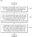
- a method for setting a discharging power limit of a battery when discharging the battery having a plurality of battery cells includes: a reference discharging power limit setting step in which a referential predetermined discharging power limit is set; a real-time discharging power limit setting step in which a real-time discharging power limit is calculated in real time according to a current voltage of the battery to set a real-time discharging power limit of the battery; and a discharging power limit restoring step in which the real-time discharging power limit set in the real-time discharging power limit setting step is restored to the referential predetermined discharging power limit.
- the real-time discharging power limit setting step may include: (a-2) a step of measuring a voltage of each of the plurality of battery cells; (b-2) a step of determining whether the voltage of a battery cell having a lowest voltage among voltages of the plurality of battery cells measured in step (a-2) is less than a preset minimum allowable voltage; (c-2) a step of measuring a period during which the voltage of the battery cell having the lowest voltage is maintained less than the preset minimum allowable voltage; and (d-2) a step of reducing the referential predetermined battery discharging power limit by a predetermined ratio to calculate the real-time discharging power limit when the period during which the voltage of the battery cell having the lowest voltage is maintained less than the preset minimum allowable voltage is equal to or longer than a predetermined period, wherein steps (a-2) to (d-2) may be repeatedly performed, and the number of times step (d-2) is performed may be counted to generate a counted value.
- the predetermined ratio by which the referential battery charging power limit is reduced may vary according to the counted value, wherein the counted value may be limited to a predetermined value, and when the counted value reaches the predetermined value, discharging of the battery may be stopped.
- the counted value may increase by 1 every time step (d-2) is performed once, and may decrease by 1 when the battery which is in a discharging state switches to a charging state.
- the battery discharging power limit may be restored to the referential predetermined discharging power limit in any one case among: a case where the counted value is 0; a case where a current does not flow in the battery for at least a predetermined time; and a case where an SOC value of the battery reaches a predetermined reference SOC value.
- a maximum output limit of a battery pack may be set in real time.
- a maximum output limit of a battery pack may be set without an additional pre-stored table of a maximum output limit according to a temperature and SOC.
- first, second or the like may be used for describing various elements but does not limit the elements. Such terms are only used for distinguishing one element from other elements. For example, without departing the scope of the present invention, a first element may be referred to as a second element, and likewise, a second element may be referred to as a first element.
- the terminology used herein is not for delimiting the present invention but for describing specific embodiments. The terms of a singular form may include plural forms unless otherwise specified.
- FIG. 1 is a flowchart illustrating the method for setting a battery charging power limit at the time of charging according to an embodiment of the present invention.
- FIG. 2 is a detailed flowchart illustrating a real-time charging power limit setting step of the method for setting a battery charging power limit at the time of charging according to an embodiment of the present invention.
- the method for setting a battery power limit at the time of charging may include a reference charging power limit setting step in which a referential predetermined charging power limit is set (S110), a real-time charging power limit setting step in which a real-time charging power limit is calculated in real time according to a current voltage of a battery to set a real-time charging power limit of the battery (S120), and a charging power limit restoring step in which the real-time charging power limit set in the real-time charging power limit setting step is restored to the referential predetermined charging power limit (S130).
- the battery may include a plurality of battery cells, and the reference charging power limit setting step may be set to a predetermined value according to specifications of each of the plurality of battery cells included in the battery and entire battery specifications when designing the battery.
- the real-time charging power limit setting step (S120) may include (a-1) a step of measuring a voltage of each of the plurality of battery cells (S121), (b-1) a step of determining whether the voltage of a battery cell having a highest voltage exceeds a preset maximum allowable voltage (S122), (c-1) a step of measuring a time during which the voltage of the battery cell having the highest voltage exceeds the preset maximum allowable voltage (S123), (d-1) a step of setting the real-time charging power limit to a value obtained by reducing the referential battery charging power limit by a predetermined ratio when a period during which the voltage of the battery cell having the highest voltage exceeds the preset maximum allowable voltage is equal to or longer than a predetermined period in step (c-1) (S124).
- steps (a-1) to (d-1) may be repeatedly performed.
- the period during which the voltage of the battery cell having the highest voltage exceeds the preset maximum allowable voltage may be measured from a point of time at which the voltage of the battery cell initially exceeds the preset maximum allowable voltage.
- Step (b-1) may be a step of determining whether the voltage of the battery cell having the highest voltage, among the plurality of battery cells, exceeds 4.2 V.
- step (c-1) when there is a battery cell having a voltage which exceeds 4.2 V in step (b-1), a period during which the voltage of the battery cell exceeds 4.2 V may be measured.
- step (d-1) when the period during which the voltage of the battery cell exceeds 4.2 V is at least 5 seconds, the battery charging power limit may be reset.
- the number of times step (d-1) is performed is counted by a counting module to generate a counted value.
- step (d-1) the predetermined ratio by which the referential battery charging power limit is reduced varies according to the counted value, wherein the counted value is limited to a predetermined value, and when the counted value reaches the predetermined value, charging of the battery may be stopped.
- the predetermined value to which the counted value is limited may be 10.
- the predetermined ratio is 0.810 according to the above equation, and may be about 1/10 of the reference charging power limit of a battery pack.
- the counted value may increase by 1 every time step (d-1) is performed once, and may decrease by 1 every time the battery which is in a charging state switches to a discharging state.
- the battery charging power limit may be restored to the referential predetermined charging power limit in any one case among a case where the counted value is 0, a case where a current does not flow in the battery for at least a predetermined time, and a case where an SOC value of the battery reaches a predetermined reference SOC value.
- the method for setting a battery charging power limit at the time of charging may easily calculate the charging power limit of the battery pack without an additional table in which a temperature or voltage and a charging power limit are set.
- the charging power limit of the battery pack may be set. Furthermore, without directly measuring a temperature of the battery pack, the charging power limit of the battery pack may be calculated.
- FIG. 3 is a flowchart illustrating the method for setting a battery discharging power limit at the time of discharging according to an embodiment of the present invention.
- FIG. 4 is a detailed flowchart illustrating a real-time charging power limit setting step of the method for setting a battery discharging power limit at the time of discharging according to an embodiment of the present invention.
- the method for setting a battery discharging power limit at the time of discharging may include a reference discharging power limit setting step in which a referential predetermined discharging power limit is set (S210), a real-time discharging power limit setting step in which a real-time discharging power limit is calculated in real time according to a current voltage of a battery to set a real-time discharging power limit of the battery (S220), and a discharging power limit restoring step in which the real-time discharging power limit set in the real-time discharging power limit setting step is restored to the referential predetermined discharging power limit (S230).
- the battery may include a plurality of battery cells
- the reference discharging power limit setting step may be set to a predetermined value according to specifications of each of the plurality of battery cells included in a battery pack and entire battery pack specifications when designing the battery pack.
- the real-time discharging power limit setting step (S220) may include (a-2) a step of measuring a voltage of each of the plurality of battery cells (S221), (b-2) a step of determining whether the voltage of a battery cell having a lowest voltage, among the plurality of battery cells, is less than a preset minimum allowable voltage (S222), (c-2) a step of measuring a time during which the voltage of the battery cell having the lowest voltage is less than the preset minimum allowable voltage (S223), (d-2) a step of reducing the referential battery discharging power limit by a prescribed ratio to calculate the real-time discharging power limit when a period during which the voltage of the battery cell having the lowest voltage is less than the preset minimum allowable voltage is equal to or longer than a predetermined period in step (c-2) (S224).
- steps (a-2) to (d-2) may be repeatedly performed.
- the period during which the voltage of the battery cell having the lowest voltage is less than the preset minimum allowable voltage may be measured from a point of time at which the voltage of the battery cell is initially less than the preset minimum allowable voltage.
- Step (b-2) may be a step of determining whether the voltage of the battery cell having the lowest voltage, among the plurality of battery cells, is less than 3.0 V.
- step (c-2) when there is a battery cell having a voltage which is less than 3.0 V in step (b-2), a time during which the voltage of the battery cell is less than 3.0 V may be measured.
- step (d-2) when the time during which the voltage of the battery cell is less than 3.0 V is at least 5 seconds, the battery discharging power limit may be reset.
- the number of times step (d-2) is performed is counted by a counting module to generate a counted value.
- step (d-2) the predetermined ratio by which the referential battery discharging power limit is reduced varies according to the counted value, wherein the counted value is limited to a predetermined value, and when the counted value reaches a predetermined value, discharging of the battery may be stopped.
- the predetermined value to which the counted value is limited may be 10.
- the predetermined ratio is 0.810 according to the above equation, and may be about 1/10 of the reference discharging power limit of a battery pack.
- the counted value may increase by 1 every time step (c-2) is performed once, and may decrease by 1 every time the battery which is in a discharging state switches to a charging state.
- the battery discharging power limit may be restored to the referential predetermined discharging power limit in any one case among a case where the counted value is 0, a case where a current does not flow in the battery for at least a predetermined time, and a case where an SOC value of the battery reaches a predetermined reference SOC value.
- the method for setting a battery discharging power limit at the time of discharging may easily calculate the discharging power limit of the battery pack without an additional table in which a temperature or voltage and a discharging power limit are set.
- the discharging power limit of the battery pack may be set. Furthermore, without directly measuring a temperature of the battery pack, the discharging power limit of the battery pack may be calculated.
Landscapes
- Engineering & Computer Science (AREA)
- Power Engineering (AREA)
- Manufacturing & Machinery (AREA)
- Chemical & Material Sciences (AREA)
- Chemical Kinetics & Catalysis (AREA)
- Electrochemistry (AREA)
- General Chemical & Material Sciences (AREA)
- Physics & Mathematics (AREA)
- General Physics & Mathematics (AREA)
- Charge And Discharge Circuits For Batteries Or The Like (AREA)
- Secondary Cells (AREA)
Priority Applications (1)
| Application Number | Priority Date | Filing Date | Title |
|---|---|---|---|
| EP23176079.4A EP4235909A3 (fr) | 2017-11-20 | 2018-10-08 | Procédé de commande de valeur limite de puissance de batterie |
Applications Claiming Priority (2)
| Application Number | Priority Date | Filing Date | Title |
|---|---|---|---|
| KR1020170155076A KR102269106B1 (ko) | 2017-11-20 | 2017-11-20 | 배터리 파워 한계 값 제어 방법 |
| PCT/KR2018/011824 WO2019098528A1 (fr) | 2017-11-20 | 2018-10-08 | Procédé de commande de valeur limite de puissance de batterie |
Related Child Applications (2)
| Application Number | Title | Priority Date | Filing Date |
|---|---|---|---|
| EP23176079.4A Division-Into EP4235909A3 (fr) | 2017-11-20 | 2018-10-08 | Procédé de commande de valeur limite de puissance de batterie |
| EP23176079.4A Division EP4235909A3 (fr) | 2017-11-20 | 2018-10-08 | Procédé de commande de valeur limite de puissance de batterie |
Publications (3)
| Publication Number | Publication Date |
|---|---|
| EP3661002A1 true EP3661002A1 (fr) | 2020-06-03 |
| EP3661002A4 EP3661002A4 (fr) | 2020-08-26 |
| EP3661002B1 EP3661002B1 (fr) | 2023-08-16 |
Family
ID=66539724
Family Applications (2)
| Application Number | Title | Priority Date | Filing Date |
|---|---|---|---|
| EP18879208.9A Active EP3661002B1 (fr) | 2017-11-20 | 2018-10-08 | Procédé de commande de valeur limite de puissance de batterie |
| EP23176079.4A Pending EP4235909A3 (fr) | 2017-11-20 | 2018-10-08 | Procédé de commande de valeur limite de puissance de batterie |
Family Applications After (1)
| Application Number | Title | Priority Date | Filing Date |
|---|---|---|---|
| EP23176079.4A Pending EP4235909A3 (fr) | 2017-11-20 | 2018-10-08 | Procédé de commande de valeur limite de puissance de batterie |
Country Status (8)
| Country | Link |
|---|---|
| US (3) | US11482875B2 (fr) |
| EP (2) | EP3661002B1 (fr) |
| JP (1) | JP7048845B2 (fr) |
| KR (1) | KR102269106B1 (fr) |
| ES (1) | ES2962565T3 (fr) |
| HU (1) | HUE063942T2 (fr) |
| PL (1) | PL3661002T3 (fr) |
| WO (1) | WO2019098528A1 (fr) |
Families Citing this family (2)
| Publication number | Priority date | Publication date | Assignee | Title |
|---|---|---|---|---|
| CN112505565B (zh) * | 2020-12-18 | 2023-06-30 | 湖北亿纬动力有限公司 | 一种电池功率测试方法 |
| KR20220102453A (ko) * | 2021-01-13 | 2022-07-20 | 주식회사 엘지에너지솔루션 | 배터리 뱅크 전력 제어 장치 및 방법 |
Family Cites Families (36)
| Publication number | Priority date | Publication date | Assignee | Title |
|---|---|---|---|---|
| JP3385837B2 (ja) | 1996-02-09 | 2003-03-10 | 日産自動車株式会社 | 電気自動車の電力制御装置 |
| DE10233821A1 (de) * | 2002-07-25 | 2004-02-05 | Daimlerchrysler Ag | Verfahren und Anordnung zur Steuerung der Energieversorgung einer wenigstens einen elektrischen Antriebsmotor aufweisenden, mobilen Vorrichtung mit einem hybriden Energiesystem, das ein Brennstoffzellensystem und ein dynamisches Energiesystem enthält |
| KR100535391B1 (ko) * | 2003-08-13 | 2005-12-08 | 현대자동차주식회사 | 배터리 가용 파워 산출방법 |
| CN101119766A (zh) * | 2004-11-18 | 2008-02-06 | 捷通心脏系统公司 | 在自动外部除颤器内进行自测试的系统和方法 |
| JP5001938B2 (ja) | 2005-06-14 | 2012-08-15 | エルジー・ケム・リミテッド | バッテリーの充電または放電出力の調整方法及び装置 |
| JP5459649B2 (ja) * | 2008-03-25 | 2014-04-02 | 株式会社東芝 | 組電池の充電方法及び組電池システム |
| CN101282045B (zh) * | 2008-04-28 | 2010-08-11 | 炬力集成电路设计有限公司 | 一种电池充电装置及其控制方法 |
| JP2010041883A (ja) * | 2008-08-07 | 2010-02-18 | Panasonic Corp | 蓄電システム |
| TWI375380B (en) | 2008-12-23 | 2012-10-21 | Richtek Technology Corp | Power system with temperature compensation control |
| WO2011007430A1 (fr) * | 2009-07-15 | 2011-01-20 | 三菱電機株式会社 | Dispositif de commande de propulsion dune voiture électrique |
| US8965721B2 (en) * | 2009-09-30 | 2015-02-24 | Tesla Motors, Inc. | Determining battery DC impedance |
| JP5556130B2 (ja) * | 2009-11-02 | 2014-07-23 | ソニー株式会社 | 情報処理装置、電源制御方法、プログラム、および電源制御システム |
| JP5537992B2 (ja) * | 2010-02-24 | 2014-07-02 | 三洋電機株式会社 | 二次電池の充電方法、二次電池の充電制御装置及びパック電池 |
| US8400112B2 (en) * | 2010-11-10 | 2013-03-19 | Ford Global Technologies, Llc | Method for managing power limits for a battery |
| JP2013133060A (ja) | 2011-12-27 | 2013-07-08 | Toyota Motor Corp | ハイブリッド車 |
| US9397611B2 (en) | 2012-03-27 | 2016-07-19 | Sunpower Corporation | Photovoltaic systems with local maximum power point tracking prevention and methods for operating same |
| US10075005B2 (en) * | 2012-10-31 | 2018-09-11 | Honda Motor Co., Ltd. | Portable electric vehicle battery discharger with physically removable power discharge modules |
| KR20140084512A (ko) | 2012-12-27 | 2014-07-07 | 주식회사 동진쎄미켐 | 전력 변환 장치 |
| US9276425B2 (en) * | 2012-12-28 | 2016-03-01 | Younicos Inc. | Power management systems with dynamic target state of charge |
| US9387773B2 (en) * | 2012-12-30 | 2016-07-12 | Lg Chem, Ltd. | System and method for derating a power limit associated with a battery pack |
| KR20140133318A (ko) * | 2013-05-10 | 2014-11-19 | 현대모비스 주식회사 | 배터리의 soc 추정 장치 및 방법 |
| KR101509895B1 (ko) * | 2013-06-28 | 2015-04-06 | 현대자동차주식회사 | 배터리 파워 제한방법 |
| CN106463997B (zh) | 2014-06-13 | 2018-04-06 | 日产自动车株式会社 | 充电控制装置以及充电控制方法 |
| CN104092269A (zh) * | 2014-07-29 | 2014-10-08 | 刘大可 | 移动电源的充电速度的衡量方法及移动电源 |
| CN105470588B (zh) * | 2014-08-21 | 2019-08-02 | 中兴通讯股份有限公司 | 一种电池信息检测控制方法、智能电池及终端 |
| KR101601714B1 (ko) | 2014-11-19 | 2016-03-09 | 현대오트론 주식회사 | 배터리 셀 밸런싱 장치 및 방법 |
| EP3046211B1 (fr) * | 2015-01-14 | 2022-01-05 | Black & Decker Inc. | Chargeur de batterie et procédé de charge de batterie |
| CN104734285B (zh) * | 2015-02-26 | 2018-04-06 | 张家港市华为电子有限公司 | 多个充电机并联时保持各机均流充电的方法 |
| US10637268B2 (en) | 2015-05-15 | 2020-04-28 | Samsung Electronics Co., Ltd. | System and method for fast charging of batteries based on dynamic cutoff voltage |
| JP6537886B2 (ja) * | 2015-05-18 | 2019-07-03 | エイブリック株式会社 | 定電流充電装置 |
| JP6767198B2 (ja) * | 2015-11-30 | 2020-10-14 | 株式会社マキタ | バッテリ装置及び充電装置 |
| US10418826B2 (en) * | 2015-11-30 | 2019-09-17 | Makita Corporation | Battery device and charging device |
| US20170271984A1 (en) * | 2016-03-04 | 2017-09-21 | Atigeo Corp. | Using battery dc characteristics to control power output |
| US9921272B2 (en) * | 2016-05-23 | 2018-03-20 | Lg Chem, Ltd. | System for determining a discharge power limit value and a charge power limit value of a battery cell |
| KR101991910B1 (ko) * | 2016-11-16 | 2019-06-21 | 주식회사 엘지화학 | 배터리의 절연 저항 산출 장치 및 방법 |
| JP2018126015A (ja) * | 2017-02-02 | 2018-08-09 | パナソニックIpマネジメント株式会社 | 充電装置及び電力需給システム |
-
2017
- 2017-11-20 KR KR1020170155076A patent/KR102269106B1/ko active IP Right Grant
-
2018
- 2018-10-08 PL PL18879208.9T patent/PL3661002T3/pl unknown
- 2018-10-08 ES ES18879208T patent/ES2962565T3/es active Active
- 2018-10-08 WO PCT/KR2018/011824 patent/WO2019098528A1/fr unknown
- 2018-10-08 JP JP2020505452A patent/JP7048845B2/ja active Active
- 2018-10-08 EP EP18879208.9A patent/EP3661002B1/fr active Active
- 2018-10-08 EP EP23176079.4A patent/EP4235909A3/fr active Pending
- 2018-10-08 HU HUE18879208A patent/HUE063942T2/hu unknown
- 2018-10-08 US US16/765,387 patent/US11482875B2/en active Active
-
2022
- 2022-09-22 US US17/950,625 patent/US20230049423A1/en active Pending
-
2023
- 2023-02-16 US US18/110,677 patent/US20230198279A1/en active Pending
Also Published As
| Publication number | Publication date |
|---|---|
| KR102269106B1 (ko) | 2021-06-24 |
| JP2020529820A (ja) | 2020-10-08 |
| KR20190057757A (ko) | 2019-05-29 |
| PL3661002T3 (pl) | 2024-02-19 |
| US11482875B2 (en) | 2022-10-25 |
| WO2019098528A1 (fr) | 2019-05-23 |
| EP3661002B1 (fr) | 2023-08-16 |
| EP3661002A4 (fr) | 2020-08-26 |
| US20200343758A1 (en) | 2020-10-29 |
| EP4235909A2 (fr) | 2023-08-30 |
| HUE063942T2 (hu) | 2024-02-28 |
| US20230049423A1 (en) | 2023-02-16 |
| JP7048845B2 (ja) | 2022-04-06 |
| ES2962565T3 (es) | 2024-03-19 |
| EP4235909A3 (fr) | 2023-11-22 |
| US20230198279A1 (en) | 2023-06-22 |
Similar Documents
| Publication | Publication Date | Title |
|---|---|---|
| US10267864B2 (en) | Battery management system including apparatus for estimating battery state | |
| CN104360285B (zh) | 一种基于改进的安时积分法的电池容量修正方法 | |
| US9287723B2 (en) | Cell balancing apparatus and method using a voltage variation pattern of each cell to estimate an open circuit voltage value for each cell | |
| CN104931882B (zh) | 动力电池容量修正的方法和装置 | |
| US7692410B2 (en) | Method and device for determining characteristics of an unknown battery | |
| US10018683B2 (en) | Apparatus and method for estimating open circuit voltage | |
| US20230049423A1 (en) | Method for controlling battery power limit value | |
| CN111123124A (zh) | 一种电池系统的功率状态的确定方法及装置 | |
| KR20120065293A (ko) | 배터리 셀의 전압 변화 거동을 이용한 셀 밸런싱 장치 및 방법 | |
| CN111301219B (zh) | 一种电动车电池控制方法、系统、设备及可读存储介质 | |
| CN112630661B (zh) | 一种电池荷电状态soc估算方法和装置 | |
| CN112470018B (zh) | Soc估计装置和方法 | |
| CN112736311B (zh) | 蓄电池的充电方法、装置和电子设备 | |
| US20220311255A1 (en) | Cell stabilizing method and system of energy storage system (ess) | |
| CN112946478B (zh) | 电池的实时可用功率的确定方法及相关设备 | |
| US20220326308A1 (en) | State-of-charge cut-off control method, apparatus and system, and storage medium | |
| US20230184838A1 (en) | Device and method for diagnosing battery | |
| US20150115970A1 (en) | Method for determining an overall loss of capacitance of a secondary cell | |
| CN112731187A (zh) | 电池容量修正方法和电池管理系统 | |
| JP7169917B2 (ja) | 二次電池の制御装置及び二次電池の制御方法 | |
| CN117022044A (zh) | 一种功率控制方法、装置、设备及存储介质 | |
| CN116001642A (zh) | 动力电池的充电方法、装置、车辆及存储介质 | |
| CN116278964A (zh) | 修正方法、装置、电子设备、车辆及存储介质 | |
| KR20230119756A (ko) | 배터리 수명 상태 추정 장치 및 방법 | |
| Berrueta Irigoyen et al. | Comparison of State-of-Charge estimation methods for stationary Lithium-ion batteries |
Legal Events
| Date | Code | Title | Description |
|---|---|---|---|
| STAA | Information on the status of an ep patent application or granted ep patent |
Free format text: STATUS: THE INTERNATIONAL PUBLICATION HAS BEEN MADE |
|
| PUAI | Public reference made under article 153(3) epc to a published international application that has entered the european phase |
Free format text: ORIGINAL CODE: 0009012 |
|
| STAA | Information on the status of an ep patent application or granted ep patent |
Free format text: STATUS: REQUEST FOR EXAMINATION WAS MADE |
|
| 17P | Request for examination filed |
Effective date: 20200227 |
|
| AK | Designated contracting states |
Kind code of ref document: A1 Designated state(s): AL AT BE BG CH CY CZ DE DK EE ES FI FR GB GR HR HU IE IS IT LI LT LU LV MC MK MT NL NO PL PT RO RS SE SI SK SM TR |
|
| AX | Request for extension of the european patent |
Extension state: BA ME |
|
| A4 | Supplementary search report drawn up and despatched |
Effective date: 20200728 |
|
| RIC1 | Information provided on ipc code assigned before grant |
Ipc: H01M 10/44 20060101ALI20200722BHEP Ipc: H02J 7/00 20060101AFI20200722BHEP |
|
| DAV | Request for validation of the european patent (deleted) | ||
| DAX | Request for extension of the european patent (deleted) | ||
| RAP1 | Party data changed (applicant data changed or rights of an application transferred) |
Owner name: LG ENERGY SOLUTION LTD. |
|
| RAP3 | Party data changed (applicant data changed or rights of an application transferred) |
Owner name: LG ENERGY SOLUTION, LTD. |
|
| GRAP | Despatch of communication of intention to grant a patent |
Free format text: ORIGINAL CODE: EPIDOSNIGR1 |
|
| STAA | Information on the status of an ep patent application or granted ep patent |
Free format text: STATUS: GRANT OF PATENT IS INTENDED |
|
| INTG | Intention to grant announced |
Effective date: 20230516 |
|
| GRAS | Grant fee paid |
Free format text: ORIGINAL CODE: EPIDOSNIGR3 |
|
| P01 | Opt-out of the competence of the unified patent court (upc) registered |
Effective date: 20230530 |
|
| GRAA | (expected) grant |
Free format text: ORIGINAL CODE: 0009210 |
|
| STAA | Information on the status of an ep patent application or granted ep patent |
Free format text: STATUS: THE PATENT HAS BEEN GRANTED |
|
| AK | Designated contracting states |
Kind code of ref document: B1 Designated state(s): AL AT BE BG CH CY CZ DE DK EE ES FI FR GB GR HR HU IE IS IT LI LT LU LV MC MK MT NL NO PL PT RO RS SE SI SK SM TR |
|
| REG | Reference to a national code |
Ref country code: CH Ref legal event code: EP |
|
| REG | Reference to a national code |
Ref country code: DE Ref legal event code: R096 Ref document number: 602018055683 Country of ref document: DE |
|
| REG | Reference to a national code |
Ref country code: IE Ref legal event code: FG4D |
|
| REG | Reference to a national code |
Ref country code: SE Ref legal event code: TRGR |
|
| REG | Reference to a national code |
Ref country code: LT Ref legal event code: MG9D |
|
| REG | Reference to a national code |
Ref country code: NL Ref legal event code: MP Effective date: 20230816 |
|
| REG | Reference to a national code |
Ref country code: AT Ref legal event code: MK05 Ref document number: 1601016 Country of ref document: AT Kind code of ref document: T Effective date: 20230816 |
|
| PG25 | Lapsed in a contracting state [announced via postgrant information from national office to epo] |
Ref country code: GR Free format text: LAPSE BECAUSE OF FAILURE TO SUBMIT A TRANSLATION OF THE DESCRIPTION OR TO PAY THE FEE WITHIN THE PRESCRIBED TIME-LIMIT Effective date: 20231117 |
|
| PGFP | Annual fee paid to national office [announced via postgrant information from national office to epo] |
Ref country code: GB Payment date: 20231023 Year of fee payment: 6 |
|
| PGFP | Annual fee paid to national office [announced via postgrant information from national office to epo] |
Ref country code: ES Payment date: 20231110 Year of fee payment: 6 |
|
| PG25 | Lapsed in a contracting state [announced via postgrant information from national office to epo] |
Ref country code: IS Free format text: LAPSE BECAUSE OF FAILURE TO SUBMIT A TRANSLATION OF THE DESCRIPTION OR TO PAY THE FEE WITHIN THE PRESCRIBED TIME-LIMIT Effective date: 20231216 |
|
| PG25 | Lapsed in a contracting state [announced via postgrant information from national office to epo] |
Ref country code: RS Free format text: LAPSE BECAUSE OF FAILURE TO SUBMIT A TRANSLATION OF THE DESCRIPTION OR TO PAY THE FEE WITHIN THE PRESCRIBED TIME-LIMIT Effective date: 20230816 Ref country code: PT Free format text: LAPSE BECAUSE OF FAILURE TO SUBMIT A TRANSLATION OF THE DESCRIPTION OR TO PAY THE FEE WITHIN THE PRESCRIBED TIME-LIMIT Effective date: 20231218 Ref country code: NO Free format text: LAPSE BECAUSE OF FAILURE TO SUBMIT A TRANSLATION OF THE DESCRIPTION OR TO PAY THE FEE WITHIN THE PRESCRIBED TIME-LIMIT Effective date: 20231116 Ref country code: NL Free format text: LAPSE BECAUSE OF FAILURE TO SUBMIT A TRANSLATION OF THE DESCRIPTION OR TO PAY THE FEE WITHIN THE PRESCRIBED TIME-LIMIT Effective date: 20230816 Ref country code: LV Free format text: LAPSE BECAUSE OF FAILURE TO SUBMIT A TRANSLATION OF THE DESCRIPTION OR TO PAY THE FEE WITHIN THE PRESCRIBED TIME-LIMIT Effective date: 20230816 Ref country code: LT Free format text: LAPSE BECAUSE OF FAILURE TO SUBMIT A TRANSLATION OF THE DESCRIPTION OR TO PAY THE FEE WITHIN THE PRESCRIBED TIME-LIMIT Effective date: 20230816 Ref country code: IS Free format text: LAPSE BECAUSE OF FAILURE TO SUBMIT A TRANSLATION OF THE DESCRIPTION OR TO PAY THE FEE WITHIN THE PRESCRIBED TIME-LIMIT Effective date: 20231216 Ref country code: HR Free format text: LAPSE BECAUSE OF FAILURE TO SUBMIT A TRANSLATION OF THE DESCRIPTION OR TO PAY THE FEE WITHIN THE PRESCRIBED TIME-LIMIT Effective date: 20230816 Ref country code: GR Free format text: LAPSE BECAUSE OF FAILURE TO SUBMIT A TRANSLATION OF THE DESCRIPTION OR TO PAY THE FEE WITHIN THE PRESCRIBED TIME-LIMIT Effective date: 20231117 Ref country code: FI Free format text: LAPSE BECAUSE OF FAILURE TO SUBMIT A TRANSLATION OF THE DESCRIPTION OR TO PAY THE FEE WITHIN THE PRESCRIBED TIME-LIMIT Effective date: 20230816 Ref country code: AT Free format text: LAPSE BECAUSE OF FAILURE TO SUBMIT A TRANSLATION OF THE DESCRIPTION OR TO PAY THE FEE WITHIN THE PRESCRIBED TIME-LIMIT Effective date: 20230816 |
|
| PGFP | Annual fee paid to national office [announced via postgrant information from national office to epo] |
Ref country code: HU Payment date: 20231116 Year of fee payment: 6 Ref country code: FR Payment date: 20231024 Year of fee payment: 6 Ref country code: DE Payment date: 20231023 Year of fee payment: 6 |
|
| REG | Reference to a national code |
Ref country code: HU Ref legal event code: AG4A Ref document number: E063942 Country of ref document: HU |
|
| REG | Reference to a national code |
Ref country code: ES Ref legal event code: FG2A Ref document number: 2962565 Country of ref document: ES Kind code of ref document: T3 Effective date: 20240319 |
|
| PG25 | Lapsed in a contracting state [announced via postgrant information from national office to epo] |
Ref country code: SM Free format text: LAPSE BECAUSE OF FAILURE TO SUBMIT A TRANSLATION OF THE DESCRIPTION OR TO PAY THE FEE WITHIN THE PRESCRIBED TIME-LIMIT Effective date: 20230816 Ref country code: RO Free format text: LAPSE BECAUSE OF FAILURE TO SUBMIT A TRANSLATION OF THE DESCRIPTION OR TO PAY THE FEE WITHIN THE PRESCRIBED TIME-LIMIT Effective date: 20230816 Ref country code: EE Free format text: LAPSE BECAUSE OF FAILURE TO SUBMIT A TRANSLATION OF THE DESCRIPTION OR TO PAY THE FEE WITHIN THE PRESCRIBED TIME-LIMIT Effective date: 20230816 Ref country code: DK Free format text: LAPSE BECAUSE OF FAILURE TO SUBMIT A TRANSLATION OF THE DESCRIPTION OR TO PAY THE FEE WITHIN THE PRESCRIBED TIME-LIMIT Effective date: 20230816 Ref country code: CZ Free format text: LAPSE BECAUSE OF FAILURE TO SUBMIT A TRANSLATION OF THE DESCRIPTION OR TO PAY THE FEE WITHIN THE PRESCRIBED TIME-LIMIT Effective date: 20230816 Ref country code: SK Free format text: LAPSE BECAUSE OF FAILURE TO SUBMIT A TRANSLATION OF THE DESCRIPTION OR TO PAY THE FEE WITHIN THE PRESCRIBED TIME-LIMIT Effective date: 20230816 |