EP3660930A1 - Herstellungsverfahren einer fotodiodenmatrix auf germaniumbasis und mit schwachem dunkelstrom - Google Patents
Herstellungsverfahren einer fotodiodenmatrix auf germaniumbasis und mit schwachem dunkelstrom Download PDFInfo
- Publication number
- EP3660930A1 EP3660930A1 EP19211790.1A EP19211790A EP3660930A1 EP 3660930 A1 EP3660930 A1 EP 3660930A1 EP 19211790 A EP19211790 A EP 19211790A EP 3660930 A1 EP3660930 A1 EP 3660930A1
- Authority
- EP
- European Patent Office
- Prior art keywords
- semiconductor
- face
- doped
- germanium
- region
- Prior art date
- Legal status (The legal status is an assumption and is not a legal conclusion. Google has not performed a legal analysis and makes no representation as to the accuracy of the status listed.)
- Granted
Links
- 229910052732 germanium Inorganic materials 0.000 title claims abstract description 61
- GNPVGFCGXDBREM-UHFFFAOYSA-N germanium atom Chemical compound [Ge] GNPVGFCGXDBREM-UHFFFAOYSA-N 0.000 title claims abstract description 61
- 238000004519 manufacturing process Methods 0.000 title claims abstract description 24
- 238000000034 method Methods 0.000 title claims abstract description 17
- 239000004065 semiconductor Substances 0.000 claims abstract description 174
- 238000002161 passivation Methods 0.000 claims abstract description 90
- 229910052710 silicon Inorganic materials 0.000 claims abstract description 37
- 239000010703 silicon Substances 0.000 claims abstract description 37
- 238000000137 annealing Methods 0.000 claims abstract description 36
- 230000002093 peripheral effect Effects 0.000 claims abstract description 25
- 239000011159 matrix material Substances 0.000 claims abstract description 18
- LEVVHYCKPQWKOP-UHFFFAOYSA-N [Si].[Ge] Chemical compound [Si].[Ge] LEVVHYCKPQWKOP-UHFFFAOYSA-N 0.000 claims abstract description 15
- 230000005693 optoelectronics Effects 0.000 claims abstract description 15
- 238000009792 diffusion process Methods 0.000 claims description 24
- 238000011049 filling Methods 0.000 claims description 14
- 238000005468 ion implantation Methods 0.000 claims description 11
- 230000015572 biosynthetic process Effects 0.000 claims description 8
- 238000000151 deposition Methods 0.000 claims description 8
- 239000003989 dielectric material Substances 0.000 claims description 8
- 230000008021 deposition Effects 0.000 abstract description 2
- 239000010410 layer Substances 0.000 description 125
- 238000001514 detection method Methods 0.000 description 47
- XUIMIQQOPSSXEZ-UHFFFAOYSA-N Silicon Chemical compound [Si] XUIMIQQOPSSXEZ-UHFFFAOYSA-N 0.000 description 37
- 239000000463 material Substances 0.000 description 20
- 230000005855 radiation Effects 0.000 description 15
- 230000007547 defect Effects 0.000 description 13
- 239000002019 doping agent Substances 0.000 description 10
- 238000001465 metallisation Methods 0.000 description 10
- 230000004048 modification Effects 0.000 description 7
- 238000012986 modification Methods 0.000 description 7
- ZOXJGFHDIHLPTG-UHFFFAOYSA-N Boron Chemical compound [B] ZOXJGFHDIHLPTG-UHFFFAOYSA-N 0.000 description 6
- 229910052796 boron Inorganic materials 0.000 description 6
- 239000000356 contaminant Substances 0.000 description 6
- 238000005530 etching Methods 0.000 description 6
- OAICVXFJPJFONN-UHFFFAOYSA-N Phosphorus Chemical compound [P] OAICVXFJPJFONN-UHFFFAOYSA-N 0.000 description 5
- 229910000577 Silicon-germanium Inorganic materials 0.000 description 5
- 229910052729 chemical element Inorganic materials 0.000 description 5
- 229910052698 phosphorus Inorganic materials 0.000 description 5
- 239000011574 phosphorus Substances 0.000 description 5
- 239000011347 resin Substances 0.000 description 5
- 229920005989 resin Polymers 0.000 description 5
- GYHNNYVSQQEPJS-UHFFFAOYSA-N Gallium Chemical compound [Ga] GYHNNYVSQQEPJS-UHFFFAOYSA-N 0.000 description 4
- VYPSYNLAJGMNEJ-UHFFFAOYSA-N Silicium dioxide Chemical compound O=[Si]=O VYPSYNLAJGMNEJ-UHFFFAOYSA-N 0.000 description 4
- 239000000969 carrier Substances 0.000 description 4
- 229910052733 gallium Inorganic materials 0.000 description 4
- 230000003071 parasitic effect Effects 0.000 description 4
- 230000002441 reversible effect Effects 0.000 description 4
- 229910052814 silicon oxide Inorganic materials 0.000 description 4
- 239000000758 substrate Substances 0.000 description 4
- 238000009825 accumulation Methods 0.000 description 3
- 229910021417 amorphous silicon Inorganic materials 0.000 description 3
- 229910052785 arsenic Inorganic materials 0.000 description 3
- RQNWIZPPADIBDY-UHFFFAOYSA-N arsenic atom Chemical compound [As] RQNWIZPPADIBDY-UHFFFAOYSA-N 0.000 description 3
- 238000004140 cleaning Methods 0.000 description 3
- 238000000407 epitaxy Methods 0.000 description 3
- 230000003287 optical effect Effects 0.000 description 3
- 229910021420 polycrystalline silicon Inorganic materials 0.000 description 3
- 230000002829 reductive effect Effects 0.000 description 3
- IJGRMHOSHXDMSA-UHFFFAOYSA-N Atomic nitrogen Chemical compound N#N IJGRMHOSHXDMSA-UHFFFAOYSA-N 0.000 description 2
- 229910052787 antimony Inorganic materials 0.000 description 2
- WATWJIUSRGPENY-UHFFFAOYSA-N antimony atom Chemical compound [Sb] WATWJIUSRGPENY-UHFFFAOYSA-N 0.000 description 2
- 230000008901 benefit Effects 0.000 description 2
- 239000002800 charge carrier Substances 0.000 description 2
- 238000005229 chemical vapour deposition Methods 0.000 description 2
- 239000013078 crystal Substances 0.000 description 2
- 238000002513 implantation Methods 0.000 description 2
- 230000001965 increasing effect Effects 0.000 description 2
- 239000012212 insulator Substances 0.000 description 2
- 229910052757 nitrogen Inorganic materials 0.000 description 2
- 230000036961 partial effect Effects 0.000 description 2
- 230000010287 polarization Effects 0.000 description 2
- 238000005036 potential barrier Methods 0.000 description 2
- 239000011241 protective layer Substances 0.000 description 2
- 238000005215 recombination Methods 0.000 description 2
- 230000003595 spectral effect Effects 0.000 description 2
- RYGMFSIKBFXOCR-UHFFFAOYSA-N Copper Chemical compound [Cu] RYGMFSIKBFXOCR-UHFFFAOYSA-N 0.000 description 1
- 229910005898 GeSn Inorganic materials 0.000 description 1
- 241000397921 Turbellaria Species 0.000 description 1
- KAJBHOLJPAFYGK-UHFFFAOYSA-N [Sn].[Ge].[Si] Chemical compound [Sn].[Ge].[Si] KAJBHOLJPAFYGK-UHFFFAOYSA-N 0.000 description 1
- 238000005299 abrasion Methods 0.000 description 1
- 238000010521 absorption reaction Methods 0.000 description 1
- 229910045601 alloy Inorganic materials 0.000 description 1
- 239000000956 alloy Substances 0.000 description 1
- 238000003491 array Methods 0.000 description 1
- 230000004888 barrier function Effects 0.000 description 1
- 230000015556 catabolic process Effects 0.000 description 1
- 238000012512 characterization method Methods 0.000 description 1
- 238000010276 construction Methods 0.000 description 1
- 238000011109 contamination Methods 0.000 description 1
- 229910052802 copper Inorganic materials 0.000 description 1
- 239000010949 copper Substances 0.000 description 1
- PMHQVHHXPFUNSP-UHFFFAOYSA-M copper(1+);methylsulfanylmethane;bromide Chemical compound Br[Cu].CSC PMHQVHHXPFUNSP-UHFFFAOYSA-M 0.000 description 1
- 230000007423 decrease Effects 0.000 description 1
- 238000006731 degradation reaction Methods 0.000 description 1
- 230000023077 detection of light stimulus Effects 0.000 description 1
- 238000006073 displacement reaction Methods 0.000 description 1
- IWTIUUVUEKAHRM-UHFFFAOYSA-N germanium tin Chemical compound [Ge].[Sn] IWTIUUVUEKAHRM-UHFFFAOYSA-N 0.000 description 1
- 238000000227 grinding Methods 0.000 description 1
- 229910000449 hafnium oxide Inorganic materials 0.000 description 1
- WIHZLLGSGQNAGK-UHFFFAOYSA-N hafnium(4+);oxygen(2-) Chemical compound [O-2].[O-2].[Hf+4] WIHZLLGSGQNAGK-UHFFFAOYSA-N 0.000 description 1
- 238000003384 imaging method Methods 0.000 description 1
- 238000010348 incorporation Methods 0.000 description 1
- 230000001939 inductive effect Effects 0.000 description 1
- 238000002955 isolation Methods 0.000 description 1
- 230000031700 light absorption Effects 0.000 description 1
- 230000000670 limiting effect Effects 0.000 description 1
- 150000002632 lipids Chemical class 0.000 description 1
- 239000007769 metal material Substances 0.000 description 1
- 230000010070 molecular adhesion Effects 0.000 description 1
- 150000004767 nitrides Chemical class 0.000 description 1
- 230000003647 oxidation Effects 0.000 description 1
- 238000007254 oxidation reaction Methods 0.000 description 1
- 238000000206 photolithography Methods 0.000 description 1
- 238000005498 polishing Methods 0.000 description 1
- 230000009467 reduction Effects 0.000 description 1
- 230000000284 resting effect Effects 0.000 description 1
- 230000002269 spontaneous effect Effects 0.000 description 1
- 230000007847 structural defect Effects 0.000 description 1
- XLYOFNOQVPJJNP-UHFFFAOYSA-N water Substances O XLYOFNOQVPJJNP-UHFFFAOYSA-N 0.000 description 1
Images


Classifications
-
- H—ELECTRICITY
- H01—ELECTRIC ELEMENTS
- H01L—SEMICONDUCTOR DEVICES NOT COVERED BY CLASS H10
- H01L31/00—Semiconductor devices sensitive to infrared radiation, light, electromagnetic radiation of shorter wavelength or corpuscular radiation and specially adapted either for the conversion of the energy of such radiation into electrical energy or for the control of electrical energy by such radiation; Processes or apparatus specially adapted for the manufacture or treatment thereof or of parts thereof; Details thereof
- H01L31/18—Processes or apparatus specially adapted for the manufacture or treatment of these devices or of parts thereof
- H01L31/186—Particular post-treatment for the devices, e.g. annealing, impurity gettering, short-circuit elimination, recrystallisation
- H01L31/1864—Annealing
-
- H—ELECTRICITY
- H01—ELECTRIC ELEMENTS
- H01L—SEMICONDUCTOR DEVICES NOT COVERED BY CLASS H10
- H01L31/00—Semiconductor devices sensitive to infrared radiation, light, electromagnetic radiation of shorter wavelength or corpuscular radiation and specially adapted either for the conversion of the energy of such radiation into electrical energy or for the control of electrical energy by such radiation; Processes or apparatus specially adapted for the manufacture or treatment thereof or of parts thereof; Details thereof
- H01L31/18—Processes or apparatus specially adapted for the manufacture or treatment of these devices or of parts thereof
- H01L31/1804—Processes or apparatus specially adapted for the manufacture or treatment of these devices or of parts thereof comprising only elements of Group IV of the Periodic Table
- H01L31/1808—Processes or apparatus specially adapted for the manufacture or treatment of these devices or of parts thereof comprising only elements of Group IV of the Periodic Table including only Ge
-
- H—ELECTRICITY
- H01—ELECTRIC ELEMENTS
- H01L—SEMICONDUCTOR DEVICES NOT COVERED BY CLASS H10
- H01L27/00—Devices consisting of a plurality of semiconductor or other solid-state components formed in or on a common substrate
- H01L27/14—Devices consisting of a plurality of semiconductor or other solid-state components formed in or on a common substrate including semiconductor components sensitive to infrared radiation, light, electromagnetic radiation of shorter wavelength or corpuscular radiation and specially adapted either for the conversion of the energy of such radiation into electrical energy or for the control of electrical energy by such radiation
- H01L27/144—Devices controlled by radiation
- H01L27/146—Imager structures
- H01L27/14643—Photodiode arrays; MOS imagers
- H01L27/14645—Colour imagers
-
- H—ELECTRICITY
- H01—ELECTRIC ELEMENTS
- H01L—SEMICONDUCTOR DEVICES NOT COVERED BY CLASS H10
- H01L21/00—Processes or apparatus adapted for the manufacture or treatment of semiconductor or solid state devices or of parts thereof
- H01L21/02—Manufacture or treatment of semiconductor devices or of parts thereof
- H01L21/02104—Forming layers
- H01L21/02365—Forming inorganic semiconducting materials on a substrate
- H01L21/02518—Deposited layers
- H01L21/02521—Materials
- H01L21/02524—Group 14 semiconducting materials
- H01L21/02532—Silicon, silicon germanium, germanium
-
- H—ELECTRICITY
- H01—ELECTRIC ELEMENTS
- H01L—SEMICONDUCTOR DEVICES NOT COVERED BY CLASS H10
- H01L21/00—Processes or apparatus adapted for the manufacture or treatment of semiconductor or solid state devices or of parts thereof
- H01L21/02—Manufacture or treatment of semiconductor devices or of parts thereof
- H01L21/02104—Forming layers
- H01L21/02365—Forming inorganic semiconducting materials on a substrate
- H01L21/02518—Deposited layers
- H01L21/0257—Doping during depositing
-
- H—ELECTRICITY
- H01—ELECTRIC ELEMENTS
- H01L—SEMICONDUCTOR DEVICES NOT COVERED BY CLASS H10
- H01L27/00—Devices consisting of a plurality of semiconductor or other solid-state components formed in or on a common substrate
- H01L27/14—Devices consisting of a plurality of semiconductor or other solid-state components formed in or on a common substrate including semiconductor components sensitive to infrared radiation, light, electromagnetic radiation of shorter wavelength or corpuscular radiation and specially adapted either for the conversion of the energy of such radiation into electrical energy or for the control of electrical energy by such radiation
- H01L27/144—Devices controlled by radiation
- H01L27/146—Imager structures
- H01L27/14601—Structural or functional details thereof
- H01L27/14638—Structures specially adapted for transferring the charges across the imager perpendicular to the imaging plane
-
- H—ELECTRICITY
- H01—ELECTRIC ELEMENTS
- H01L—SEMICONDUCTOR DEVICES NOT COVERED BY CLASS H10
- H01L27/00—Devices consisting of a plurality of semiconductor or other solid-state components formed in or on a common substrate
- H01L27/14—Devices consisting of a plurality of semiconductor or other solid-state components formed in or on a common substrate including semiconductor components sensitive to infrared radiation, light, electromagnetic radiation of shorter wavelength or corpuscular radiation and specially adapted either for the conversion of the energy of such radiation into electrical energy or for the control of electrical energy by such radiation
- H01L27/144—Devices controlled by radiation
- H01L27/146—Imager structures
- H01L27/14643—Photodiode arrays; MOS imagers
- H01L27/14649—Infrared imagers
-
- H—ELECTRICITY
- H01—ELECTRIC ELEMENTS
- H01L—SEMICONDUCTOR DEVICES NOT COVERED BY CLASS H10
- H01L27/00—Devices consisting of a plurality of semiconductor or other solid-state components formed in or on a common substrate
- H01L27/14—Devices consisting of a plurality of semiconductor or other solid-state components formed in or on a common substrate including semiconductor components sensitive to infrared radiation, light, electromagnetic radiation of shorter wavelength or corpuscular radiation and specially adapted either for the conversion of the energy of such radiation into electrical energy or for the control of electrical energy by such radiation
- H01L27/144—Devices controlled by radiation
- H01L27/146—Imager structures
- H01L27/14683—Processes or apparatus peculiar to the manufacture or treatment of these devices or parts thereof
- H01L27/14689—MOS based technologies
-
- H—ELECTRICITY
- H01—ELECTRIC ELEMENTS
- H01L—SEMICONDUCTOR DEVICES NOT COVERED BY CLASS H10
- H01L27/00—Devices consisting of a plurality of semiconductor or other solid-state components formed in or on a common substrate
- H01L27/14—Devices consisting of a plurality of semiconductor or other solid-state components formed in or on a common substrate including semiconductor components sensitive to infrared radiation, light, electromagnetic radiation of shorter wavelength or corpuscular radiation and specially adapted either for the conversion of the energy of such radiation into electrical energy or for the control of electrical energy by such radiation
- H01L27/144—Devices controlled by radiation
- H01L27/146—Imager structures
- H01L27/14683—Processes or apparatus peculiar to the manufacture or treatment of these devices or parts thereof
- H01L27/14698—Post-treatment for the devices, e.g. annealing, impurity-gettering, shor-circuit elimination, recrystallisation
-
- H—ELECTRICITY
- H01—ELECTRIC ELEMENTS
- H01L—SEMICONDUCTOR DEVICES NOT COVERED BY CLASS H10
- H01L31/00—Semiconductor devices sensitive to infrared radiation, light, electromagnetic radiation of shorter wavelength or corpuscular radiation and specially adapted either for the conversion of the energy of such radiation into electrical energy or for the control of electrical energy by such radiation; Processes or apparatus specially adapted for the manufacture or treatment thereof or of parts thereof; Details thereof
- H01L31/02—Details
- H01L31/0216—Coatings
- H01L31/02161—Coatings for devices characterised by at least one potential jump barrier or surface barrier
-
- H—ELECTRICITY
- H01—ELECTRIC ELEMENTS
- H01L—SEMICONDUCTOR DEVICES NOT COVERED BY CLASS H10
- H01L31/00—Semiconductor devices sensitive to infrared radiation, light, electromagnetic radiation of shorter wavelength or corpuscular radiation and specially adapted either for the conversion of the energy of such radiation into electrical energy or for the control of electrical energy by such radiation; Processes or apparatus specially adapted for the manufacture or treatment thereof or of parts thereof; Details thereof
- H01L31/02—Details
- H01L31/0232—Optical elements or arrangements associated with the device
- H01L31/02327—Optical elements or arrangements associated with the device the optical elements being integrated or being directly associated to the device, e.g. back reflectors
-
- H—ELECTRICITY
- H01—ELECTRIC ELEMENTS
- H01L—SEMICONDUCTOR DEVICES NOT COVERED BY CLASS H10
- H01L31/00—Semiconductor devices sensitive to infrared radiation, light, electromagnetic radiation of shorter wavelength or corpuscular radiation and specially adapted either for the conversion of the energy of such radiation into electrical energy or for the control of electrical energy by such radiation; Processes or apparatus specially adapted for the manufacture or treatment thereof or of parts thereof; Details thereof
- H01L31/0248—Semiconductor devices sensitive to infrared radiation, light, electromagnetic radiation of shorter wavelength or corpuscular radiation and specially adapted either for the conversion of the energy of such radiation into electrical energy or for the control of electrical energy by such radiation; Processes or apparatus specially adapted for the manufacture or treatment thereof or of parts thereof; Details thereof characterised by their semiconductor bodies
- H01L31/0256—Semiconductor devices sensitive to infrared radiation, light, electromagnetic radiation of shorter wavelength or corpuscular radiation and specially adapted either for the conversion of the energy of such radiation into electrical energy or for the control of electrical energy by such radiation; Processes or apparatus specially adapted for the manufacture or treatment thereof or of parts thereof; Details thereof characterised by their semiconductor bodies characterised by the material
- H01L31/0264—Inorganic materials
- H01L31/028—Inorganic materials including, apart from doping material or other impurities, only elements of Group IV of the Periodic Table
-
- H—ELECTRICITY
- H01—ELECTRIC ELEMENTS
- H01L—SEMICONDUCTOR DEVICES NOT COVERED BY CLASS H10
- H01L31/00—Semiconductor devices sensitive to infrared radiation, light, electromagnetic radiation of shorter wavelength or corpuscular radiation and specially adapted either for the conversion of the energy of such radiation into electrical energy or for the control of electrical energy by such radiation; Processes or apparatus specially adapted for the manufacture or treatment thereof or of parts thereof; Details thereof
- H01L31/0248—Semiconductor devices sensitive to infrared radiation, light, electromagnetic radiation of shorter wavelength or corpuscular radiation and specially adapted either for the conversion of the energy of such radiation into electrical energy or for the control of electrical energy by such radiation; Processes or apparatus specially adapted for the manufacture or treatment thereof or of parts thereof; Details thereof characterised by their semiconductor bodies
- H01L31/0256—Semiconductor devices sensitive to infrared radiation, light, electromagnetic radiation of shorter wavelength or corpuscular radiation and specially adapted either for the conversion of the energy of such radiation into electrical energy or for the control of electrical energy by such radiation; Processes or apparatus specially adapted for the manufacture or treatment thereof or of parts thereof; Details thereof characterised by their semiconductor bodies characterised by the material
- H01L31/0264—Inorganic materials
- H01L31/0312—Inorganic materials including, apart from doping materials or other impurities, only AIVBIV compounds, e.g. SiC
-
- H—ELECTRICITY
- H01—ELECTRIC ELEMENTS
- H01L—SEMICONDUCTOR DEVICES NOT COVERED BY CLASS H10
- H01L31/00—Semiconductor devices sensitive to infrared radiation, light, electromagnetic radiation of shorter wavelength or corpuscular radiation and specially adapted either for the conversion of the energy of such radiation into electrical energy or for the control of electrical energy by such radiation; Processes or apparatus specially adapted for the manufacture or treatment thereof or of parts thereof; Details thereof
- H01L31/0248—Semiconductor devices sensitive to infrared radiation, light, electromagnetic radiation of shorter wavelength or corpuscular radiation and specially adapted either for the conversion of the energy of such radiation into electrical energy or for the control of electrical energy by such radiation; Processes or apparatus specially adapted for the manufacture or treatment thereof or of parts thereof; Details thereof characterised by their semiconductor bodies
- H01L31/0352—Semiconductor devices sensitive to infrared radiation, light, electromagnetic radiation of shorter wavelength or corpuscular radiation and specially adapted either for the conversion of the energy of such radiation into electrical energy or for the control of electrical energy by such radiation; Processes or apparatus specially adapted for the manufacture or treatment thereof or of parts thereof; Details thereof characterised by their semiconductor bodies characterised by their shape or by the shapes, relative sizes or disposition of the semiconductor regions
- H01L31/035272—Semiconductor devices sensitive to infrared radiation, light, electromagnetic radiation of shorter wavelength or corpuscular radiation and specially adapted either for the conversion of the energy of such radiation into electrical energy or for the control of electrical energy by such radiation; Processes or apparatus specially adapted for the manufacture or treatment thereof or of parts thereof; Details thereof characterised by their semiconductor bodies characterised by their shape or by the shapes, relative sizes or disposition of the semiconductor regions characterised by at least one potential jump barrier or surface barrier
-
- H—ELECTRICITY
- H01—ELECTRIC ELEMENTS
- H01L—SEMICONDUCTOR DEVICES NOT COVERED BY CLASS H10
- H01L31/00—Semiconductor devices sensitive to infrared radiation, light, electromagnetic radiation of shorter wavelength or corpuscular radiation and specially adapted either for the conversion of the energy of such radiation into electrical energy or for the control of electrical energy by such radiation; Processes or apparatus specially adapted for the manufacture or treatment thereof or of parts thereof; Details thereof
- H01L31/08—Semiconductor devices sensitive to infrared radiation, light, electromagnetic radiation of shorter wavelength or corpuscular radiation and specially adapted either for the conversion of the energy of such radiation into electrical energy or for the control of electrical energy by such radiation; Processes or apparatus specially adapted for the manufacture or treatment thereof or of parts thereof; Details thereof in which radiation controls flow of current through the device, e.g. photoresistors
- H01L31/10—Semiconductor devices sensitive to infrared radiation, light, electromagnetic radiation of shorter wavelength or corpuscular radiation and specially adapted either for the conversion of the energy of such radiation into electrical energy or for the control of electrical energy by such radiation; Processes or apparatus specially adapted for the manufacture or treatment thereof or of parts thereof; Details thereof in which radiation controls flow of current through the device, e.g. photoresistors characterised by potential barriers, e.g. phototransistors
- H01L31/101—Devices sensitive to infrared, visible or ultraviolet radiation
- H01L31/102—Devices sensitive to infrared, visible or ultraviolet radiation characterised by only one potential barrier
- H01L31/103—Devices sensitive to infrared, visible or ultraviolet radiation characterised by only one potential barrier the potential barrier being of the PN homojunction type
-
- H—ELECTRICITY
- H01—ELECTRIC ELEMENTS
- H01L—SEMICONDUCTOR DEVICES NOT COVERED BY CLASS H10
- H01L31/00—Semiconductor devices sensitive to infrared radiation, light, electromagnetic radiation of shorter wavelength or corpuscular radiation and specially adapted either for the conversion of the energy of such radiation into electrical energy or for the control of electrical energy by such radiation; Processes or apparatus specially adapted for the manufacture or treatment thereof or of parts thereof; Details thereof
- H01L31/08—Semiconductor devices sensitive to infrared radiation, light, electromagnetic radiation of shorter wavelength or corpuscular radiation and specially adapted either for the conversion of the energy of such radiation into electrical energy or for the control of electrical energy by such radiation; Processes or apparatus specially adapted for the manufacture or treatment thereof or of parts thereof; Details thereof in which radiation controls flow of current through the device, e.g. photoresistors
- H01L31/10—Semiconductor devices sensitive to infrared radiation, light, electromagnetic radiation of shorter wavelength or corpuscular radiation and specially adapted either for the conversion of the energy of such radiation into electrical energy or for the control of electrical energy by such radiation; Processes or apparatus specially adapted for the manufacture or treatment thereof or of parts thereof; Details thereof in which radiation controls flow of current through the device, e.g. photoresistors characterised by potential barriers, e.g. phototransistors
- H01L31/101—Devices sensitive to infrared, visible or ultraviolet radiation
- H01L31/102—Devices sensitive to infrared, visible or ultraviolet radiation characterised by only one potential barrier
- H01L31/105—Devices sensitive to infrared, visible or ultraviolet radiation characterised by only one potential barrier the potential barrier being of the PIN type
-
- H—ELECTRICITY
- H01—ELECTRIC ELEMENTS
- H01L—SEMICONDUCTOR DEVICES NOT COVERED BY CLASS H10
- H01L31/00—Semiconductor devices sensitive to infrared radiation, light, electromagnetic radiation of shorter wavelength or corpuscular radiation and specially adapted either for the conversion of the energy of such radiation into electrical energy or for the control of electrical energy by such radiation; Processes or apparatus specially adapted for the manufacture or treatment thereof or of parts thereof; Details thereof
- H01L31/18—Processes or apparatus specially adapted for the manufacture or treatment of these devices or of parts thereof
- H01L31/1804—Processes or apparatus specially adapted for the manufacture or treatment of these devices or of parts thereof comprising only elements of Group IV of the Periodic Table
-
- Y—GENERAL TAGGING OF NEW TECHNOLOGICAL DEVELOPMENTS; GENERAL TAGGING OF CROSS-SECTIONAL TECHNOLOGIES SPANNING OVER SEVERAL SECTIONS OF THE IPC; TECHNICAL SUBJECTS COVERED BY FORMER USPC CROSS-REFERENCE ART COLLECTIONS [XRACs] AND DIGESTS
- Y02—TECHNOLOGIES OR APPLICATIONS FOR MITIGATION OR ADAPTATION AGAINST CLIMATE CHANGE
- Y02P—CLIMATE CHANGE MITIGATION TECHNOLOGIES IN THE PRODUCTION OR PROCESSING OF GOODS
- Y02P70/00—Climate change mitigation technologies in the production process for final industrial or consumer products
- Y02P70/50—Manufacturing or production processes characterised by the final manufactured product
Definitions
- the field of the invention is that of photodiodes made from germanium.
- the invention finds an application in particular in the field of detection of light radiation belonging to the near infrared.
- Germanium-based photodiodes are suitable for detecting light radiation in the near infrared (SWIR, for Short Wavelength IR , in English). Their use is advantageous especially when it comes to detecting the presence of chemical elements whose spectral signature is located in the SWIR range. It can thus be water, lipids, chemical elements present in biological tissues, etc. They are also used in the telecommunications field, as well as in that of datacom.
- SWIR near infrared
- Germanium-based photodiodes usually have a mesa structure, in which the diodes are produced from a stack of semiconductor layers, including a doped p-type lower layer resting on a growth substrate, an intrinsic intermediate layer, and an n-type doped upper layer. Pixelization between the photodiodes is obtained by localized etching, so that the lateral border of each photodiode can then be defined by each of the semiconductor layers.
- the upper face of the n-doped layer and the lateral border are then coated with a passivation layer made of a dielectric material, for example a silicon oxide.
- the dielectric passivation layer extends in three dimensions so as to cover the photodiode, and not in an essentially planar manner.
- the article by Sood et al. titled Characterization of SiGe-Detector Arrays for Visible-NIR Imaging Sensor Applications, Proc. of SPIE VOL. 8012, 801240, 2011 describes a method of manufacturing a photodiode making it possible to limit the dark current.
- the dark current is related to the presence of a depleted zone located in the semiconductor material of the photodiode, at the interface with the dielectric passivation layer.
- the manufacturing process then includes a step of annealing the photodiode under N 2 H 2 , making it possible to transform this depleted area into a hole accumulation area. It appears that this step makes it possible to reduce the intensity of the dark current.
- this annealing step intended to modify the depleted zone into an accumulation zone, can induce a degradation of the performances of the photodiode, in particular due to an undesired modification of the dimensions of the n-doped layer, in the measure where the diffusion coefficient of n-type doping elements in germanium (eg phosphorus) can be large.
- the presence and the characteristics of the depleted zone can be linked to the technique used for depositing the dielectric passivation layer as well as to the operating conditions. As a result, the annealing in question may then not make it possible to reproducibly obtain the desired accumulation zone and therefore the desired reduction in the dark current.
- the object of the invention is to remedy at least in part the drawbacks of the prior art, and more particularly to propose a method for manufacturing a matrix of germanium-based planar photodiodes, thus having a high filling factor, and making it possible to obtain a low dark current while preserving the properties of the photodiodes, and in particular the dimensions of the n-doped region (s).
- the method may include a step of doping so-called lateral parts of the semiconductor passivation layer, located in the trenches, by localized ion implantation of p-type doping elements, thus forming for each photodiode a p-doped lateral part, followed by an annealing step ensuring the diffusion of p-type doping elements from the lateral parts towards the semiconductor portions, thus forming, in each semiconductor portion, a so-called p-doped lateral region flush with a lateral border of the semiconductor portion.
- the diffusion annealing step of the p-type doping elements can be carried out before or during the diffusion annealing step of the n-type doping elements.
- the semiconductor passivation layer may comprise a so-called upper part extending in contact with the second face, and a so-called lateral part filling the trenches and extending in contact with the side edge, the upper part comprising a so-called central portion doped with type n and located in contact with the second n-doped region, and a so-called peripheral portion, surrounding the central portion in the main plane.
- the lateral part can be p-type doped, and be in contact with the first p-doped region.
- Each semiconductor portion may comprise a so-called p-type doped lateral region and located in contact with the p-doped lateral part.
- the optoelectronic device may include a control chip adapted to polarize the photodiodes, assembled and electrically connected to the array of photodiodes at the second face.
- the invention relates generally to a method of manufacturing an optoelectronic device comprising a matrix of photodiodes made from germanium.
- Each photodiode is thus adapted to detect light radiation in the near infrared (SWIR, for Short Wavelength IR , in English) corresponding to the spectral range going from 0.8 ⁇ m to approximately 1.7 ⁇ m, or even to 2.5 ⁇ m approximately.
- SWIR near infrared
- Photodiodes are said to be planar insofar as they extend along the same main plane, between first and second faces which are parallel and opposite to each other. They each comprise a so-called detection semiconductor portion, within which there is a PN or PIN junction, having a substantially constant thickness between the first and second faces.
- Each photodiode comprises a first so-called lower p-type doped region which is flush with the first face continuously a second so-called n-doped upper region locally and locally flush with the second face and forming a doped well, and an intermediate region located between the two doped regions and surrounding the second doped region in the main plane.
- This intermediate region can be p-type doped, to form a PN junction, or be intrinsic, that is to say unintentionally doped, to form a PIN junction.
- the planar photodiodes then do not have a mesa structure, and are optically isolated from each other by trenches filled here by a part of a semiconductor passivation layer made from silicon. They therefore have a particularly high filling factor.
- the photodiodes are said to be passivated insofar as the second face as well as the lateral border defined by the trenches are coated with the semiconductor passivation layer produced on the basis of silicon.
- the semiconductor passivation layer is in particular intended to reduce the surface component of the dark current of each photodiode. It is advantageously used to apply an electrical potential to the first p + doped region from the second face.
- the dark current of a photodiode is the electric current present within the photodiode in operation, when it is not subjected to light radiation. It can be formed from thermally generated currents inside the volume of the semiconductor detection portion (diffusion currents, depletion currents, tunnel currents, etc.) and surface currents.
- Surface currents can also be linked to the presence of defects in the semiconductor material of the photodiode, these defects being located in particular near the surfaces of the semiconductor detection portion, in particular at the level of the lateral border and of the second face. These defects can come from localized etching carried out to form the trenches, as well as from the unwanted incorporation of contaminants during technological stages of the manufacturing process. These defects can be at the origin of the creation of minority carriers in the absence of radiation luminous. These non-photogenerated minority carriers can then diffuse up to the space charge zone of the photodiode and create an electric current, here a dark current.
- the manufacturing method thus makes it possible to obtain a matrix of planar photodiodes produced on the basis of germanium, passivated by a semiconductor passivation layer produced on the basis of silicon, and covering the second face as well as the lateral border in the trenches.
- the semiconductor detection portion of each photodiode includes a so-called peripheral zone made from germanium silicon.
- a peripheral zone has a higher silicon concentration than that which the detection semiconductor portion may possibly have, so that it has a band gap energy greater than that of the portion semiconductor detection.
- This peripheral “gap opening” is then located where surface defects and potential contaminants are present, which makes it possible to limit the parasitic currents on the surface of the dark current.
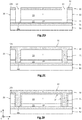
- the figure 1 is a partial and schematic view, in cross section, of such a passivated planar photodiode 2 belonging to a matrix of photodiodes 2 made from germanium. They are here polarized, for example in reverse, from the second face 10b and are passivated and optically isolated from each other by a semiconductor passivation layer 30 extending on the second face 10b and filling trenches 13 of pixelation.
- Each photodiode 2 comprises a semiconductor detection portion 20 extending along the axis Z between a first and a second face 10a, 10b parallel and opposite to each other, and is delimited in the XY plane by a lateral border 20c which connects the two faces together.
- the first and second faces 10a, 10b are common to each photodiode 2 of the matrix. They can be substantially planar, so that the semiconductor detection portion 20 has a thickness along the axis Z which is substantially constant, for example between a few hundred nanometers and a few microns, for example between about 1 ⁇ m and 10 ⁇ m. The thickness is chosen so as to obtain good absorption in the wavelength range of the light radiation to be detected.
- the semiconductor detection portion 20 has a transverse dimension in the XY plane which can be between a few hundred nanometers and a few tens of microns, for example between 1 ⁇ m and 100 ⁇ m, preferably between 1 ⁇ m and 20 ⁇ m approximately.
- the detection semiconductor portion 20 is made of a crystalline semiconductor material based on germanium, preferably monocrystalline. By based on a chemical element of interest, it is meant that the crystalline semiconductor material corresponds to the chemical element of interest or is an alloy formed of at least the chemical element of interest.
- Photodiodes 2 can therefore be made of germanium Ge, silicon germanium SiGe, tin germanium GeSn, or silicon germanium tin SiGeSn.
- the semiconductor detection portion 20 comes from at least one layer made of germanium. It can thus be a layer or a substrate made of the same semiconductor material based on germanium and have regions of different types of conductivity (homojunction) to form a PN or PIN junction.
- the first region 21 doped here p + extends in the XY plane by being flush with the first face 10a, here from the lateral border 20c. It extends along the axis Z from the first face 10a. It may have a substantially homogeneous thickness along the axis Z and thus only be flush with a lower zone of the lateral border 20c.
- the first p + doped region 21 can advantageously have a p + doped lateral region 25 which is flush with the lateral border 20c along the Z axis and extends over the entire periphery of the detection semiconductor portion 20.
- the first p + doped region 21 may have doping which may be between 10 18 and 10 20 at / cm 3 approximately.
- the second n + doped region 22 here extends from the second face 10b and is surrounded by the intermediate region 23 in the main plane. It is distant from the lateral border 20c of the semiconductor detection portion 20 in the XY plane. It thus forms an n-doped box which is flush with the second face 10b and is spaced apart by a non-zero distance from the side edge 20c as well as from the first face 10a.
- the second doped n region 22 thus participates in delimiting the second face 10b. It may have a doping which may be between 10 19 and 10 21 at / cm 3 approximately.
- the optoelectronic device 1 may comprise a lower insulating layer 51, made of a dielectric material, covering the first face 10a of the semiconductor detection portion 20, as well as, as described below, the lower face of trenches 13 filled with a material passivation semiconductor based on silicon.
- the trench 13 can then participate in electrically polarizing the photodiode, here from the second face, and in pixelating the matrix of photodiodes 2 (optical isolation).
- the lower insulating layer 51 can also be adapted to form an anti-reflection function vis-à-vis the incident light radiation. It indeed forms the receiving face of the light radiation intended to be detected.
- each photodiode 2 is delimited laterally, in the XY plane, by a trench 13, preferably continuous, which here extends over the entire thickness of the semiconductor detection portion 20 to lead to the layer lower insulating 51.
- the trench 13 may not lead to the lower insulating layer 51 and may terminate in the first p + doped region 21.
- the trenches 13 may have transverse dimensions, in the XY plane, of the order of 0.5 ⁇ m to 2.0 ⁇ m.
- a semiconductor passivation layer 30 continuously covers the second face 10b and completely fills the trenches 13. It is thus in contact with the first p + doped region 21 at the side border 20c, the intermediate region 23 at the side border 20c and of the second face 10b, and of the second n + doped region 22 at the level of the second face 10b. It is made of a semiconductor material based on silicon. It is thus formed of an upper part 32 in contact with the second face 10b and of a side part 31 filling the trench 13. The upper part 32 and side 31 form two continuous, joined zones, of the same semiconductor layer. passivation 30. This is made from silicon, and can be, for example, amorphous silicon, polycrystalline silicon, silicon germanium. The passivation semiconductor layer 30 has a higher silicon concentration than that of the germanium-based semiconductor material of the detection semiconductor portion 20. The upper part 32 may have a thickness, along the axis Z, for example between 100 nm and 1 ⁇ m.
- defects in the germanium-based semiconductor material may be present near the side edge 20c and the second face 10b of the detection semiconductor portion 20. These defects may arise, as regards the side edge 20c, localized etching carried out to obtain the trenches 13. As regards the second face 10b, they can come from contaminating elements incorporated in an unwanted manner during technological steps implemented during the manufacturing process. These defects and these contaminants can introduce an intermediate level of energy into the forbidden energy band of the germanium-based semiconductor material, which can then allow the spontaneous passage of a charge carrier from an energy band to a other, thus creating an electron-hole pair and therefore a minority carrier. When it diffuses to the space charge zone, it can then contribute to the dark current.
- the semiconductor passivation layer 30 therefore makes it possible to reduce the parasitic surface currents and consequently to reduce the dark current. Furthermore, this gap opening also results in the formation of a potential barrier vis-à-vis the photogenerated minority carriers which would diffuse towards crystal defects and contaminants located near the side border 20c and the second side 10b. This prevents photogenerated carriers from recombining without being detected and from participating in the useful electrical detection signal. The performance of the photodiodes 2 is then improved.
- the interdiffusion annealing does not lead to a significant modification of the dimensions of the first p + doped region 21, insofar as the p type doping elements in germanium (boron, gallium ... ) have a reduced diffusion coefficient.
- the n-type doping elements in germanium phosphorus, arsenic, antimony, etc.
- the interdiffusion annealing then advantageously being carried out before the step of producing the second n + doped regions 22 .
- the detection semiconductor portion 20 advantageously comprises a p + type doped lateral region 25, situated at the level of the lateral border 20c.
- This lateral region 25 has a higher doping level than that of the intermediate region 23 when it is doped.
- the p + doped lateral region 25 is flush with the lateral border 20c and is in contact with the p + doped lateral part 31. As described below, it is obtained during the interdiffusion annealing, or during a specific diffusion annealing of the doping elements.
- the polarization of the first p + doped region 21 is improved insofar as the contact surface with the lateral part 31 p + doped is increased.
- this p + doped lateral region 25 makes it possible to prevent the space charge zone of the photodiode 2 from extending to the lateral border 20c.
- the contribution of this zone is limited to the dark current. This improves the performance of photodiode 2.
- the electric circuit here comprises contact metallizations 41 extending through through openings of an upper insulating layer 40 which covers the semiconductor passivation layer 30, and coming into contact with the lateral parts 31 doped p + on the one hand, and of the central portion 32.1 doped n + on the other hand.
- the contact metallizations 41 here have a lower part 41.1 coming into contact with the doped areas 31, 32.1 of the semiconductor passivation layer 30, and an upper part 41.2 flush with the upper face and having dimensions in the XY plane larger than those of the lower part 41.1.
- the contact metallizations 41 here also play a role of reflector with respect to the incident light radiation coming from the first face 10a (the latter playing the role of optical reception face). This improves the absorbed proportion of the incident light radiation in the semiconductor detection portion 20.
- the passivation semiconductor layer 30 was obtained by depositing an intrinsic semiconductor material based on silicon. Also, the side part 31 doped p + and the central portion 32.1 doped n + are electrically isolated from each other by a peripheral portion 32.2 made based on intrinsic silicon, and therefore having a high electrical resistivity, close to that of materials. dielectric, for example greater than 10 9 ⁇ .cm. Also, any risk of short circuit between the lateral part 31 doped p + and the central portion 32.1 doped n +, when they are polarized, is thus eliminated.
- the photodiodes 2 are made of germanium and include a PIN junction, and are adapted to detect infrared radiation in the SWIR range.
- the photodiodes 2 are planar, and are passivated by a semiconductor passivation layer 30 which extends both in contact with the second face 10b and in contact with the side edge 20c in the trenches 13. This semiconductor passivation layer 30 allows advantageously to ensure the polarization, for example in reverse, of each photodiode 2 from the second face 10b.
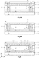
- a first semiconductor layer 11 of monocrystalline germanium is produced.
- the first semiconductor layer 11 is secured to a support layer 50, here made of silicon, by means of a lower insulating layer 51, here made of a silicon oxide.
- This stack takes the form of a GeOI substrate (for Germanium On Insulator, in English). This stacking is preferably carried out by means of the method described in the publication of Reboud et al. titled Structural and optical properties of 200mm germanium-on-insulator (GeOI) substrates for silicon photonics applications, Proc. SPIE 9367, Silicon Photonics X, 936714 (February 27, 2015 ).
- Such a method has the advantage of producing a semiconductor layer 11 of germanium having an absence or a low rate of structural defects such as dislocations.
- the germanium can be unintentionally doped or be doped, for example of the p type.
- the semiconductor layer 11 may have a thickness of between 20 nm and approximately 500 nm, for example equal to approximately 300 nm, and may be covered with a protective layer (not shown) made of a silicon oxide.
- the lower insulating layer 51 (BOX, for Buried Oxide , in English) may have a thickness of between 50 nm and 1 ⁇ m and advantageously provides an anti-reflection function.
- a second semiconductor layer 12 of germanium is produced by epitaxy from the first layer 11.
- the two layers 11, 12 are intended to form the semiconductor detection portions 10 coplanar in germanium of the photodiodes matrix 2.
- the second layer 12 is formed by epitaxy, for example by chemical vapor deposition (CVD, for Chemical Vapor Deposition, in English) or by any other epitaxy technique. This layer can undergo various anneals to reduce the rate of dislocations.
- the pre-implementation oxide layer, if any, has been previously removed by surface cleaning.
- the second layer 12 of germanium is here intrinsic, that is to say unintentionally doped. It is intended to form the light absorption zone of photodiodes 2.
- the second layer 12 of intrinsic germanium has a thickness for example of between 0.5 ⁇ m and 3 ⁇ m, preferably equal to 1.5 ⁇ m.
- a so-called upper part 32 of the passivation semiconductor layer 30 is deposited so as to continuously cover the upper face 10b of the second layer 12, that is to say so as to cover what the different semiconductor portions of photodiodes detection 2. This reduces the risk of contamination or oxidation of the germanium surface.
- the passivation semiconductor layer 30 is produced on the basis of an intrinsic semiconductor material, and more precisely on the basis of silicon, for example amorphous silicon, polycrystalline silicon, or germanium silicon. A cleaning of the upper face 10b of the second layer 12 may have been carried out.
- the upper part 32 of the semiconductor passivation layer 30 may have a thickness of between 3 nm and 500 nm. As a variant, it is possible to produce the trenches 13 before the deposition of the passivation semiconductor layer 30.
- the trenches 13 intended to pixelate the photodiodes 2 and to participate here in electrically polarizing them, for example in reverse, are then produced by photolithography and etching. This produces a localized etching of the upper part 32 of the semiconductor passivation layer 30, of the second layer 12 of intrinsic germanium, and of the first layer 11 of p + doped germanium, until it leads here to the lower insulating layer 51
- Each trench 13 thus preferably extends continuously around a photodiode 2. This gives a plurality of semiconductor detection portions 20 separated from each other by a trench 13 keep on going.
- Each semiconductor detection portion 20 is here formed of a first p + doped region 21 and of an intermediate region 23 here intrinsic.
- the trenches 13 are preferably obtained by an anisotropic etching technique, so as to obtain a substantially vertical lateral border 20c along the axis Z.
- the trenches 13 have a transverse dimension (width) in the XY plane which can be between 300 nm and 2 ⁇ m, for example equal to 1 ⁇ m.
- the semiconductor detection portions 20 can thus have a shape in the XY plane, for example circular, oval, polygonal, for example square, or any other shape.
- the lateral part 31 of the passivation semiconductor layer 30 is then produced.
- an intrinsic semiconductor material based on silicon is deposited so as to completely fill the trenches 13.
- the semiconductor material is preferably identical to that of the upper part 32 of the semiconductor passivation layer 30, namely amorphous silicon, polycrystalline silicon, or germanium silicon.
- a semiconductor passivation layer 30 obtained based on intrinsic silicon is obtained, the upper part 32 of which extends in contact with the second face 10b and the lateral part 31 fills the trench 13 and extends in contact with the edge lateral 20c.
- the lateral parts 31 and upper part 32 are two parts of the same continuous semiconductor layer.
- a mechanochemical polishing step (CMP) can then be carried out, to planarize the upper face of the passivation semiconductor layer 30.
- the lateral 31 and upper 32 parts of the passivation semiconductor layer 30 can be obtained simultaneously, by depositing an intrinsic semiconductor material based on silicon so as to extend in contact with the second face 10b and to fill the trench 13.
- an annealing is then carried out ensuring the interdiffusion between the silicon of the semiconductor passivation layer 30 and the germanium of the semiconductor detection portion 20.
- This peripheral zone 24 then has a concentration of silicon greater than the concentration of silicon that the semiconductor detection portion 20 can have outside this zone.
- the interdiffusion annealing can be carried out at a temperature for example of the order of 700 ° C. to 850 ° C. for a period of the order of 30 minutes to 10 hours.
- the peripheral zone 24 has a gap greater than that of the semiconductor detection portion 20 outside this zone 24.
- This peripheral zone 24 with "gap opening" thus makes it possible to effectively passivate the semiconductor detection portion 20 and reduce the surface component of the current darkness associated with the presence of crystalline defects and / or unwanted contaminants. It also forms a potential barrier making it possible to reduce the risk that a photogenerated minority carrier will recombine in this peripheral zone 24 without being detected by photodiode 2.
- a next step ( fig. 2G ), an ion implantation of p-type doping elements, for example boron, is carried out in the lateral part 31 of the passivation semiconductor layer 30 so as to obtain a lateral part 31 doped p + over its entire thickness, with a level doping for example between 10 19 and 10 21 at / cm 3 .
- the ion implantation is carried out in a localized manner through a through opening made in a photosensitive resin 52.
- the photosensitive resin is then removed.
- the semiconductor passivation layer 30 comprises a p + doped lateral part 31 which is flush with the upper face of the semiconductor passivation layer 30, and an intrinsic upper part 32.
- an annealing is advantageously carried out ensuring the diffusion of p-type doping elements (boron) from the p + doped side portion 31 towards the detection semiconductor portion 20 via the side edge 20c.
- a p + doped lateral region 25 is thus obtained extending in the semiconductor detection portion 20 along the axis Z at the level of the lateral border 20c.
- Diffusion annealing of p dopants can be carried out at a temperature for example between 700 ° C and 850 ° C, for a period for example between 10min and 5h.
- the interdiffusion annealing and the diffusion annealing can be the same annealing performed after p-type doping of the lateral part 31 of the passivation semiconductor layer 30.
- the second n + doped region 22 of the detection semiconductor portion 20 is then produced, here in two stages.
- an ion implantation zone of n-type dopants for example phosphorus, arsenic or antimony, is defined by means of a through opening of a photosensitive resin 53 ( fig. 2I ).
- the through opening is located opposite a central zone of the photodiode 2, and has dimensions in the XY plane corresponding to the desired dimensions of the second n + doped region 22. They can be included, for example between 300nm and 90 ⁇ m.
- a dopant such as phosphorus is carried out, through the opening of the photosensitive resin 53, in a central portion 32.1 initially intrinsic of the semiconductor passivation layer 30, to make it doped n +.
- the photosensitive resin 53 can then be removed.
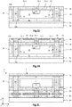
- at least one annealing is carried out ensuring the diffusion of the doping elements n from the central portion 32.1 doped n + of the semiconductor passivation layer 30 towards the semiconductor detection portion 20, for example at a first temperature of 800 ° C. for 5 min then at a second temperature between 600 ° C and 700 ° C for 5s to 60s.
- the second n + doped region 22 is thus obtained.
- the second n + doped region 22 thus forms a doped well delimited in the XY plane and in the direction -Z by the intermediate region 23 of intrinsic germanium. It is preferably overdoped n +, and can thus have a doping level of the order of 10 19 at / cm 3 .
- the annealing of interdiffusion of silicon and germanium as well as diffusion annealing of p-type doping elements are carried out before the production of the second n + doped region 22, the latter having controlled dimensions.
- the n-type doping elements in germanium phosphorus, arsenic, etc.
- the p-type doping elements boron, gallium, etc.
- the dimensions of the p + doped lateral region 25 are not substantially or only slightly modified, and the dimensions of the second n + doped region 22 correspond to those desired.
- an electrical interconnection layer is then produced.
- an upper insulating layer 40 is deposited so as to continuously cover the semiconductor passivation layer 30. It can be made of a dielectric material, for example an oxide, nitride or oxynitride of silicon, an oxide or aluminum nitride, hafnium oxide, among others.
- the upper insulating layer 40 may have a thickness for example of between 10 nm and 500 nm.
- Annealing under N 2 H 2 eg 90% N 2 and 10% H 2
- contact metallizations 41 are produced, extending through the upper insulating layer 40, and coming into contact with the central portion 32.1 doped n + on the one hand, and the lateral part 31 doped with p + on the other hand .
- the intrinsic peripheral portion 32.2 of the semiconductor passivation layer 30 is not in contact with a contact metallization.
- the contact metallizations 41 can be carried out in a conventional manner, by filling the openings passing through the upper insulating layer 40 with at least one metallic material (barrier layer based on Ti, copper core), followed by a CMP planarization step. .
- Each contact metallization 41 may have a lower part 41.1 in contact with the semiconductor passivation layer 30, and an upper part 41.2 flush with the upper face of the upper insulating layer 40.
- the upper part 41.2 advantageously has transverse dimensions, in the plane XY, greater than those of the lower part 41.1, and thus provides an additional function of reflection of the light radiation received through the first face 10a, the latter forming the receiving face of the light radiation to be detected.
- the optoelectronic stack thus obtained is hybridized on a control chip 60.
- the connection face of the control chip 60 can thus be coated with an insulating layer 61, made of a dielectric material, traversed by contact metallizations 62.
- the optoelectronic stack and the control chip 60 are thus assembled by hybrid molecular adhesion, by contact of the faces formed from contact metallizations 41, 62 and insulating layers 40, 61.
- a bonding annealing can be carried out in such a way as to increase the surface bonding energy between the two faces in contact.
- the support layer 50 is then removed, for example by abrasion ( grinding , in English), so as to expose the lower insulating layer 51. This thus forms the receiving face of the light radiation to be detected, and advantageously ensures an anti-reflection function.
- the manufacturing process thus makes it possible to obtain a matrix of 2 planar photodiodes produced based on germanium, the lateral edge 20c and the second face 10b of which are passivated by a semiconductor passivation layer 30 produced based on silicon.
- the peripheral zone 24 based on silicon germanium thus formed makes it possible to limit the surface components of the dark current.
- the manufacturing process makes it possible to preserve the dimensions of the second n + doped region 22.
- any risk of short circuit of the photodiodes 2 by an excessive modification of the dimensions of the second doped regions 22 is thus eliminated.
- the performance of photodiodes 2 is also improved in particular by the following characteristics: the p-doped lateral regions 25 situated at the level of the lateral border 20c, the wide upper parts 41.2 of contact metallizations 41, the second doped regions 22 obtained by diffusion of dopants and not by ion implantation directly in the semiconductor detection portion 20.
- the lateral part 31 of the semiconductor passivation layer 30 may not be p-type doped.
- the first p-doped region 21 can then be polarized from an electrical contact located at the first face 10a.
Landscapes
- Engineering & Computer Science (AREA)
- Physics & Mathematics (AREA)
- Power Engineering (AREA)
- Condensed Matter Physics & Semiconductors (AREA)
- General Physics & Mathematics (AREA)
- Computer Hardware Design (AREA)
- Microelectronics & Electronic Packaging (AREA)
- Electromagnetism (AREA)
- Manufacturing & Machinery (AREA)
- Chemical & Material Sciences (AREA)
- Inorganic Chemistry (AREA)
- Light Receiving Elements (AREA)
Applications Claiming Priority (1)
| Application Number | Priority Date | Filing Date | Title |
|---|---|---|---|
| FR1872106A FR3089348B1 (fr) | 2018-11-30 | 2018-11-30 | procede de fabrication d’une matrice de diodes a base de germanium et a faible courant d’obscurité |
Publications (2)
| Publication Number | Publication Date |
|---|---|
| EP3660930A1 true EP3660930A1 (de) | 2020-06-03 |
| EP3660930B1 EP3660930B1 (de) | 2021-03-31 |
Family
ID=66286436
Family Applications (1)
| Application Number | Title | Priority Date | Filing Date |
|---|---|---|---|
| EP19211790.1A Active EP3660930B1 (de) | 2018-11-30 | 2019-11-27 | Herstellungsverfahren einer fotodiodenmatrix auf germaniumbasis und mit schwachem dunkelstrom |
Country Status (3)
| Country | Link |
|---|---|
| US (2) | US11264425B2 (de) |
| EP (1) | EP3660930B1 (de) |
| FR (1) | FR3089348B1 (de) |
Cited By (3)
| Publication number | Priority date | Publication date | Assignee | Title |
|---|---|---|---|---|
| EP3971995A1 (de) | 2020-09-21 | 2022-03-23 | Commissariat à l'énergie atomique et aux énergies alternatives | Passivierte fotodiode mit einem ferroelektrischen peripheren teil |
| FR3119711A1 (fr) * | 2021-02-11 | 2022-08-12 | Commissariat à l'Energie Atomique et aux Energies Alternatives | Photodiode germanium à contacts métalliques optimisés |
| EP4354524A1 (de) | 2022-10-14 | 2024-04-17 | Commissariat à l'Énergie Atomique et aux Énergies Alternatives | Planare photodiode auf germaniumbasis mit einer kompressiven peripheren seitlichen zone |
Families Citing this family (3)
| Publication number | Priority date | Publication date | Assignee | Title |
|---|---|---|---|---|
| FR3101727B1 (fr) * | 2019-10-08 | 2021-09-17 | Commissariat Energie Atomique | procede de fabrication d’au moins une photodiode planaire contrainte en tension |
| US11600737B2 (en) * | 2021-03-16 | 2023-03-07 | Taiwan Semiconductor Manufacturing Company, Ltd. | Germanium-based sensor with junction-gate field effect transistor and method of fabricating thereof |
| FR3129248B1 (fr) * | 2021-11-17 | 2023-11-03 | Commissariat Energie Atomique | Photodiode germanium à courant d’obscurité réduit comportant une portion intermédiaire périphérique à base de SiGe/Ge |
Citations (3)
| Publication number | Priority date | Publication date | Assignee | Title |
|---|---|---|---|---|
| US20110272561A1 (en) * | 2010-03-23 | 2011-11-10 | Stmicroelectronics S.R.L. | Method of detecting impinging position of photons on a geiger-mode avalanche photodiode, related geiger-mode avalanche photodiode and fabrication process |
| US20170012143A1 (en) * | 2015-07-07 | 2017-01-12 | Renesas Electronics Corporation | Semiconductor device and method of manufacturing the same |
| CN107871800A (zh) * | 2017-02-24 | 2018-04-03 | 乔丽萍 | n+‑GeSn/i‑GeSn/p+‑Ge结构光电探测器及其制备方法 |
Family Cites Families (6)
| Publication number | Priority date | Publication date | Assignee | Title |
|---|---|---|---|---|
| US7397101B1 (en) * | 2004-07-08 | 2008-07-08 | Luxtera, Inc. | Germanium silicon heterostructure photodetectors |
| US7361528B2 (en) * | 2005-02-28 | 2008-04-22 | Sharp Laboratories Of America, Inc. | Germanium infrared sensor for CMOS imagers |
| US20070170536A1 (en) * | 2006-01-25 | 2007-07-26 | Sharp Laboratories Of America, Inc. | Liquid phase epitaxial GOI photodiode with buried high resistivity germanium layer |
| US20100006961A1 (en) * | 2008-07-09 | 2010-01-14 | Analog Devices, Inc. | Recessed Germanium (Ge) Diode |
| CN103367381B (zh) * | 2013-07-15 | 2016-12-28 | 格科微电子(上海)有限公司 | 背照式图像传感器及其制作方法 |
| US9659989B1 (en) * | 2016-04-19 | 2017-05-23 | Omnivision Technologies, Inc. | Image sensor with semiconductor trench isolation |
-
2018
- 2018-11-30 FR FR1872106A patent/FR3089348B1/fr not_active Expired - Fee Related
-
2019
- 2019-11-26 US US16/695,265 patent/US11264425B2/en active Active
- 2019-11-27 EP EP19211790.1A patent/EP3660930B1/de active Active
-
2021
- 2021-12-02 US US17/540,323 patent/US20220093674A1/en active Pending
Patent Citations (3)
| Publication number | Priority date | Publication date | Assignee | Title |
|---|---|---|---|---|
| US20110272561A1 (en) * | 2010-03-23 | 2011-11-10 | Stmicroelectronics S.R.L. | Method of detecting impinging position of photons on a geiger-mode avalanche photodiode, related geiger-mode avalanche photodiode and fabrication process |
| US20170012143A1 (en) * | 2015-07-07 | 2017-01-12 | Renesas Electronics Corporation | Semiconductor device and method of manufacturing the same |
| CN107871800A (zh) * | 2017-02-24 | 2018-04-03 | 乔丽萍 | n+‑GeSn/i‑GeSn/p+‑Ge结构光电探测器及其制备方法 |
Non-Patent Citations (1)
| Title |
|---|
| SOOD ET AL.: "haracterization of SiGe-Detector Arrays for Visible-NIR Imaging Sensor Applications", PROC. OF SPIE, vol. 8012, 2011, pages 801240 |
Cited By (6)
| Publication number | Priority date | Publication date | Assignee | Title |
|---|---|---|---|---|
| EP3971995A1 (de) | 2020-09-21 | 2022-03-23 | Commissariat à l'énergie atomique et aux énergies alternatives | Passivierte fotodiode mit einem ferroelektrischen peripheren teil |
| FR3114440A1 (fr) | 2020-09-21 | 2022-03-25 | Commissariat A L'energie Atomique Et Aux Energies Alternatives | Photodiode passivée comportant une portion périphérique ferroélectrique |
| FR3119711A1 (fr) * | 2021-02-11 | 2022-08-12 | Commissariat à l'Energie Atomique et aux Energies Alternatives | Photodiode germanium à contacts métalliques optimisés |
| WO2022171650A1 (fr) * | 2021-02-11 | 2022-08-18 | Commissariat A L'energie Atomique Et Aux Energies Alternatives | Photodiode germanium a contacts metalliques optimises |
| EP4354524A1 (de) | 2022-10-14 | 2024-04-17 | Commissariat à l'Énergie Atomique et aux Énergies Alternatives | Planare photodiode auf germaniumbasis mit einer kompressiven peripheren seitlichen zone |
| FR3140992A1 (fr) | 2022-10-14 | 2024-04-19 | Commissariat A L'energie Atomique Et Aux Energies Alternatives | Photodiode planaire à base de germanium comportant une zone latérale périphérique en compression |
Also Published As
| Publication number | Publication date |
|---|---|
| US20200176503A1 (en) | 2020-06-04 |
| US11264425B2 (en) | 2022-03-01 |
| EP3660930B1 (de) | 2021-03-31 |
| FR3089348B1 (fr) | 2020-10-30 |
| US20220093674A1 (en) | 2022-03-24 |
| CN111261748A (zh) | 2020-06-09 |
| FR3089348A1 (fr) | 2020-06-05 |
Similar Documents
| Publication | Publication Date | Title |
|---|---|---|
| EP3660930B1 (de) | Herstellungsverfahren einer fotodiodenmatrix auf germaniumbasis und mit schwachem dunkelstrom | |
| EP3657556B1 (de) | Herstellungsverfahren mindestens einer passivierten planaren fotodiode mit reduziertem dunkelstrom | |
| FR2954587A1 (fr) | Procede de formation d'un capteur d'images eclaire par la face arriere | |
| EP3971995B1 (de) | Passivierte fotodiode mit einem ferroelektrischen peripheren teil | |
| EP3806167B1 (de) | Verfahren zur herstellung mindestens einer planaren fotodiode unter spannung | |
| WO2019202250A1 (fr) | Dispositif optoelectronique a diode contrainte en tension par effet piezoelectrique inverse | |
| FR2694134A1 (fr) | Procédé de fabrication d'une diode photovoltaïque et diode à structure plane. | |
| WO2010061151A2 (fr) | Procede de fabrication de cellules matricielles photosensibles dans l'infrarouge collees par adhesion moleculaire sur substrat optiquement transparent et capteur associe | |
| EP4184594B1 (de) | Germanium-photodiode mit reduziertem dunkelstrom mit einem auf sige/ge basierenden peripheren zwischenteil | |
| EP0913002B1 (de) | Zweifarbiger infrarotdetektor mit räumlich-zeitlicher kohärenz | |
| EP3109900A1 (de) | Herstellungsverfahren einer vielzahl von dipolen in form von inseln, die selbstausrichtende elektroden umfassen | |
| FR2974240A1 (fr) | Capteur eclaire par la face arriere a isolement par jonction | |
| EP1677364A1 (de) | Lichtdetektor auf einer integrierten Schaltung sitzend | |
| FR3091024A1 (fr) | Photodiode à avalanche à photon unique | |
| WO2022171650A1 (fr) | Photodiode germanium a contacts metalliques optimises | |
| CN111261748B (zh) | 用于制造具有低暗电流的基于锗的二极管阵列的方法 | |
| EP3764403B1 (de) | Herstellung einer fotosensiblen vorrichtung mit halbleiter | |
| EP4354524A1 (de) | Planare photodiode auf germaniumbasis mit einer kompressiven peripheren seitlichen zone | |
| WO2023110412A1 (fr) | Capteur d'images visibles et infrarouges et procédé de fabrication d'un tel capteur | |
| EP4092739A1 (de) | Verfahren zur herstellung einer optoelektronischen vorrichtung, entsprechende vorrichtung und system mit dieser vorrichtung | |
| EP3671843A1 (de) | Herstellungsverfahren einer vielzahl von dioden aus einem lesesubstrat | |
| FR3112421A1 (fr) | Procédé de réalisation d’une structure d’isolation | |
| FR2742581A1 (fr) | Detecteur infrarouge bicolore a coherence spatio-temporelle planaire |
Legal Events
| Date | Code | Title | Description |
|---|---|---|---|
| PUAI | Public reference made under article 153(3) epc to a published international application that has entered the european phase |
Free format text: ORIGINAL CODE: 0009012 |
|
| STAA | Information on the status of an ep patent application or granted ep patent |
Free format text: STATUS: REQUEST FOR EXAMINATION WAS MADE |
|
| 17P | Request for examination filed |
Effective date: 20191127 |
|
| AK | Designated contracting states |
Kind code of ref document: A1 Designated state(s): AL AT BE BG CH CY CZ DE DK EE ES FI FR GB GR HR HU IE IS IT LI LT LU LV MC MK MT NL NO PL PT RO RS SE SI SK SM TR |
|
| AX | Request for extension of the european patent |
Extension state: BA ME |
|
| GRAP | Despatch of communication of intention to grant a patent |
Free format text: ORIGINAL CODE: EPIDOSNIGR1 |
|
| STAA | Information on the status of an ep patent application or granted ep patent |
Free format text: STATUS: GRANT OF PATENT IS INTENDED |
|
| INTG | Intention to grant announced |
Effective date: 20210113 |
|
| GRAS | Grant fee paid |
Free format text: ORIGINAL CODE: EPIDOSNIGR3 |
|
| GRAA | (expected) grant |
Free format text: ORIGINAL CODE: 0009210 |
|
| STAA | Information on the status of an ep patent application or granted ep patent |
Free format text: STATUS: THE PATENT HAS BEEN GRANTED |
|
| AK | Designated contracting states |
Kind code of ref document: B1 Designated state(s): AL AT BE BG CH CY CZ DE DK EE ES FI FR GB GR HR HU IE IS IT LI LT LU LV MC MK MT NL NO PL PT RO RS SE SI SK SM TR |
|
| REG | Reference to a national code |
Ref country code: GB Ref legal event code: FG4D Free format text: NOT ENGLISH Ref country code: CH Ref legal event code: EP |
|
| REG | Reference to a national code |
Ref country code: AT Ref legal event code: REF Ref document number: 1377932 Country of ref document: AT Kind code of ref document: T Effective date: 20210415 |
|
| REG | Reference to a national code |
Ref country code: DE Ref legal event code: R096 Ref document number: 602019003603 Country of ref document: DE |
|
| REG | Reference to a national code |
Ref country code: IE Ref legal event code: FG4D Free format text: LANGUAGE OF EP DOCUMENT: FRENCH |
|
| REG | Reference to a national code |
Ref country code: LT Ref legal event code: MG9D |
|
| PG25 | Lapsed in a contracting state [announced via postgrant information from national office to epo] |
Ref country code: BG Free format text: LAPSE BECAUSE OF FAILURE TO SUBMIT A TRANSLATION OF THE DESCRIPTION OR TO PAY THE FEE WITHIN THE PRESCRIBED TIME-LIMIT Effective date: 20210630 Ref country code: HR Free format text: LAPSE BECAUSE OF FAILURE TO SUBMIT A TRANSLATION OF THE DESCRIPTION OR TO PAY THE FEE WITHIN THE PRESCRIBED TIME-LIMIT Effective date: 20210331 Ref country code: FI Free format text: LAPSE BECAUSE OF FAILURE TO SUBMIT A TRANSLATION OF THE DESCRIPTION OR TO PAY THE FEE WITHIN THE PRESCRIBED TIME-LIMIT Effective date: 20210331 Ref country code: NO Free format text: LAPSE BECAUSE OF FAILURE TO SUBMIT A TRANSLATION OF THE DESCRIPTION OR TO PAY THE FEE WITHIN THE PRESCRIBED TIME-LIMIT Effective date: 20210630 |
|
| PG25 | Lapsed in a contracting state [announced via postgrant information from national office to epo] |
Ref country code: LV Free format text: LAPSE BECAUSE OF FAILURE TO SUBMIT A TRANSLATION OF THE DESCRIPTION OR TO PAY THE FEE WITHIN THE PRESCRIBED TIME-LIMIT Effective date: 20210331 Ref country code: RS Free format text: LAPSE BECAUSE OF FAILURE TO SUBMIT A TRANSLATION OF THE DESCRIPTION OR TO PAY THE FEE WITHIN THE PRESCRIBED TIME-LIMIT Effective date: 20210331 Ref country code: SE Free format text: LAPSE BECAUSE OF FAILURE TO SUBMIT A TRANSLATION OF THE DESCRIPTION OR TO PAY THE FEE WITHIN THE PRESCRIBED TIME-LIMIT Effective date: 20210331 |
|
| REG | Reference to a national code |
Ref country code: NL Ref legal event code: MP Effective date: 20210331 |
|
| REG | Reference to a national code |
Ref country code: AT Ref legal event code: MK05 Ref document number: 1377932 Country of ref document: AT Kind code of ref document: T Effective date: 20210331 |
|
| PG25 | Lapsed in a contracting state [announced via postgrant information from national office to epo] |
Ref country code: AT Free format text: LAPSE BECAUSE OF FAILURE TO SUBMIT A TRANSLATION OF THE DESCRIPTION OR TO PAY THE FEE WITHIN THE PRESCRIBED TIME-LIMIT Effective date: 20210331 Ref country code: SM Free format text: LAPSE BECAUSE OF FAILURE TO SUBMIT A TRANSLATION OF THE DESCRIPTION OR TO PAY THE FEE WITHIN THE PRESCRIBED TIME-LIMIT Effective date: 20210331 Ref country code: NL Free format text: LAPSE BECAUSE OF FAILURE TO SUBMIT A TRANSLATION OF THE DESCRIPTION OR TO PAY THE FEE WITHIN THE PRESCRIBED TIME-LIMIT Effective date: 20210331 Ref country code: LT Free format text: LAPSE BECAUSE OF FAILURE TO SUBMIT A TRANSLATION OF THE DESCRIPTION OR TO PAY THE FEE WITHIN THE PRESCRIBED TIME-LIMIT Effective date: 20210331 Ref country code: CZ Free format text: LAPSE BECAUSE OF FAILURE TO SUBMIT A TRANSLATION OF THE DESCRIPTION OR TO PAY THE FEE WITHIN THE PRESCRIBED TIME-LIMIT Effective date: 20210331 Ref country code: EE Free format text: LAPSE BECAUSE OF FAILURE TO SUBMIT A TRANSLATION OF THE DESCRIPTION OR TO PAY THE FEE WITHIN THE PRESCRIBED TIME-LIMIT Effective date: 20210331 |
|
| PG25 | Lapsed in a contracting state [announced via postgrant information from national office to epo] |
Ref country code: IS Free format text: LAPSE BECAUSE OF FAILURE TO SUBMIT A TRANSLATION OF THE DESCRIPTION OR TO PAY THE FEE WITHIN THE PRESCRIBED TIME-LIMIT Effective date: 20210731 Ref country code: PL Free format text: LAPSE BECAUSE OF FAILURE TO SUBMIT A TRANSLATION OF THE DESCRIPTION OR TO PAY THE FEE WITHIN THE PRESCRIBED TIME-LIMIT Effective date: 20210331 Ref country code: RO Free format text: LAPSE BECAUSE OF FAILURE TO SUBMIT A TRANSLATION OF THE DESCRIPTION OR TO PAY THE FEE WITHIN THE PRESCRIBED TIME-LIMIT Effective date: 20210331 Ref country code: PT Free format text: LAPSE BECAUSE OF FAILURE TO SUBMIT A TRANSLATION OF THE DESCRIPTION OR TO PAY THE FEE WITHIN THE PRESCRIBED TIME-LIMIT Effective date: 20210802 Ref country code: SK Free format text: LAPSE BECAUSE OF FAILURE TO SUBMIT A TRANSLATION OF THE DESCRIPTION OR TO PAY THE FEE WITHIN THE PRESCRIBED TIME-LIMIT Effective date: 20210331 |
|
| REG | Reference to a national code |
Ref country code: DE Ref legal event code: R097 Ref document number: 602019003603 Country of ref document: DE |
|
| PG25 | Lapsed in a contracting state [announced via postgrant information from national office to epo] |
Ref country code: AL Free format text: LAPSE BECAUSE OF FAILURE TO SUBMIT A TRANSLATION OF THE DESCRIPTION OR TO PAY THE FEE WITHIN THE PRESCRIBED TIME-LIMIT Effective date: 20210331 Ref country code: DK Free format text: LAPSE BECAUSE OF FAILURE TO SUBMIT A TRANSLATION OF THE DESCRIPTION OR TO PAY THE FEE WITHIN THE PRESCRIBED TIME-LIMIT Effective date: 20210331 Ref country code: ES Free format text: LAPSE BECAUSE OF FAILURE TO SUBMIT A TRANSLATION OF THE DESCRIPTION OR TO PAY THE FEE WITHIN THE PRESCRIBED TIME-LIMIT Effective date: 20210331 |
|
| PLBE | No opposition filed within time limit |
Free format text: ORIGINAL CODE: 0009261 |
|
| STAA | Information on the status of an ep patent application or granted ep patent |
Free format text: STATUS: NO OPPOSITION FILED WITHIN TIME LIMIT |
|
| 26N | No opposition filed |
Effective date: 20220104 |
|
| PG25 | Lapsed in a contracting state [announced via postgrant information from national office to epo] |
Ref country code: IS Free format text: LAPSE BECAUSE OF FAILURE TO SUBMIT A TRANSLATION OF THE DESCRIPTION OR TO PAY THE FEE WITHIN THE PRESCRIBED TIME-LIMIT Effective date: 20210731 |
|
| PG25 | Lapsed in a contracting state [announced via postgrant information from national office to epo] |
Ref country code: MC Free format text: LAPSE BECAUSE OF FAILURE TO SUBMIT A TRANSLATION OF THE DESCRIPTION OR TO PAY THE FEE WITHIN THE PRESCRIBED TIME-LIMIT Effective date: 20210331 |
|
| PG25 | Lapsed in a contracting state [announced via postgrant information from national office to epo] |
Ref country code: LU Free format text: LAPSE BECAUSE OF NON-PAYMENT OF DUE FEES Effective date: 20211127 Ref country code: IT Free format text: LAPSE BECAUSE OF FAILURE TO SUBMIT A TRANSLATION OF THE DESCRIPTION OR TO PAY THE FEE WITHIN THE PRESCRIBED TIME-LIMIT Effective date: 20210331 Ref country code: BE Free format text: LAPSE BECAUSE OF NON-PAYMENT OF DUE FEES Effective date: 20211130 |
|
| REG | Reference to a national code |
Ref country code: BE Ref legal event code: MM Effective date: 20211130 |
|
| PG25 | Lapsed in a contracting state [announced via postgrant information from national office to epo] |
Ref country code: IE Free format text: LAPSE BECAUSE OF NON-PAYMENT OF DUE FEES Effective date: 20211127 |
|
| PG25 | Lapsed in a contracting state [announced via postgrant information from national office to epo] |
Ref country code: CY Free format text: LAPSE BECAUSE OF FAILURE TO SUBMIT A TRANSLATION OF THE DESCRIPTION OR TO PAY THE FEE WITHIN THE PRESCRIBED TIME-LIMIT Effective date: 20210331 |
|
| REG | Reference to a national code |
Ref country code: CH Ref legal event code: PL |
|
| PG25 | Lapsed in a contracting state [announced via postgrant information from national office to epo] |
Ref country code: LI Free format text: LAPSE BECAUSE OF NON-PAYMENT OF DUE FEES Effective date: 20221130 Ref country code: HU Free format text: LAPSE BECAUSE OF FAILURE TO SUBMIT A TRANSLATION OF THE DESCRIPTION OR TO PAY THE FEE WITHIN THE PRESCRIBED TIME-LIMIT; INVALID AB INITIO Effective date: 20191127 Ref country code: GR Free format text: LAPSE BECAUSE OF FAILURE TO SUBMIT A TRANSLATION OF THE DESCRIPTION OR TO PAY THE FEE WITHIN THE PRESCRIBED TIME-LIMIT Effective date: 20210331 Ref country code: CH Free format text: LAPSE BECAUSE OF NON-PAYMENT OF DUE FEES Effective date: 20221130 |
|
| PGFP | Annual fee paid to national office [announced via postgrant information from national office to epo] |
Ref country code: GB Payment date: 20231123 Year of fee payment: 5 |
|
| PGFP | Annual fee paid to national office [announced via postgrant information from national office to epo] |
Ref country code: FR Payment date: 20231120 Year of fee payment: 5 Ref country code: DE Payment date: 20231120 Year of fee payment: 5 |
|
| PG25 | Lapsed in a contracting state [announced via postgrant information from national office to epo] |
Ref country code: MK Free format text: LAPSE BECAUSE OF FAILURE TO SUBMIT A TRANSLATION OF THE DESCRIPTION OR TO PAY THE FEE WITHIN THE PRESCRIBED TIME-LIMIT Effective date: 20210331 |