EP3971995B1 - Passivierte fotodiode mit einem ferroelektrischen peripheren teil - Google Patents
Passivierte fotodiode mit einem ferroelektrischen peripheren teil Download PDFInfo
- Publication number
- EP3971995B1 EP3971995B1 EP21197570.1A EP21197570A EP3971995B1 EP 3971995 B1 EP3971995 B1 EP 3971995B1 EP 21197570 A EP21197570 A EP 21197570A EP 3971995 B1 EP3971995 B1 EP 3971995B1
- Authority
- EP
- European Patent Office
- Prior art keywords
- region
- photodiode
- peripheral
- doped
- ferroelectric
- Prior art date
- Legal status (The legal status is an assumption and is not a legal conclusion. Google has not performed a legal analysis and makes no representation as to the accuracy of the status listed.)
- Active
Links
Images


Classifications
-
- H—ELECTRICITY
- H10—SEMICONDUCTOR DEVICES; ELECTRIC SOLID-STATE DEVICES NOT OTHERWISE PROVIDED FOR
- H10F—INORGANIC SEMICONDUCTOR DEVICES SENSITIVE TO INFRARED RADIATION, LIGHT, ELECTROMAGNETIC RADIATION OF SHORTER WAVELENGTH OR CORPUSCULAR RADIATION
- H10F30/00—Individual radiation-sensitive semiconductor devices in which radiation controls the flow of current through the devices, e.g. photodetectors
- H10F30/20—Individual radiation-sensitive semiconductor devices in which radiation controls the flow of current through the devices, e.g. photodetectors the devices having potential barriers, e.g. phototransistors
- H10F30/21—Individual radiation-sensitive semiconductor devices in which radiation controls the flow of current through the devices, e.g. photodetectors the devices having potential barriers, e.g. phototransistors the devices being sensitive to infrared, visible or ultraviolet radiation
- H10F30/22—Individual radiation-sensitive semiconductor devices in which radiation controls the flow of current through the devices, e.g. photodetectors the devices having potential barriers, e.g. phototransistors the devices being sensitive to infrared, visible or ultraviolet radiation the devices having only one potential barrier, e.g. photodiodes
- H10F30/223—Individual radiation-sensitive semiconductor devices in which radiation controls the flow of current through the devices, e.g. photodetectors the devices having potential barriers, e.g. phototransistors the devices being sensitive to infrared, visible or ultraviolet radiation the devices having only one potential barrier, e.g. photodiodes the potential barrier being a PIN barrier
-
- H—ELECTRICITY
- H10—SEMICONDUCTOR DEVICES; ELECTRIC SOLID-STATE DEVICES NOT OTHERWISE PROVIDED FOR
- H10F—INORGANIC SEMICONDUCTOR DEVICES SENSITIVE TO INFRARED RADIATION, LIGHT, ELECTROMAGNETIC RADIATION OF SHORTER WAVELENGTH OR CORPUSCULAR RADIATION
- H10F39/00—Integrated devices, or assemblies of multiple devices, comprising at least one element covered by group H10F30/00, e.g. radiation detectors comprising photodiode arrays
- H10F39/011—Manufacture or treatment of image sensors covered by group H10F39/12
- H10F39/014—Manufacture or treatment of image sensors covered by group H10F39/12 of CMOS image sensors
-
- H—ELECTRICITY
- H10—SEMICONDUCTOR DEVICES; ELECTRIC SOLID-STATE DEVICES NOT OTHERWISE PROVIDED FOR
- H10F—INORGANIC SEMICONDUCTOR DEVICES SENSITIVE TO INFRARED RADIATION, LIGHT, ELECTROMAGNETIC RADIATION OF SHORTER WAVELENGTH OR CORPUSCULAR RADIATION
- H10F39/00—Integrated devices, or assemblies of multiple devices, comprising at least one element covered by group H10F30/00, e.g. radiation detectors comprising photodiode arrays
- H10F39/10—Integrated devices
- H10F39/103—Integrated devices the at least one element covered by H10F30/00 having potential barriers, e.g. integrated devices comprising photodiodes or phototransistors
-
- H—ELECTRICITY
- H10—SEMICONDUCTOR DEVICES; ELECTRIC SOLID-STATE DEVICES NOT OTHERWISE PROVIDED FOR
- H10F—INORGANIC SEMICONDUCTOR DEVICES SENSITIVE TO INFRARED RADIATION, LIGHT, ELECTROMAGNETIC RADIATION OF SHORTER WAVELENGTH OR CORPUSCULAR RADIATION
- H10F39/00—Integrated devices, or assemblies of multiple devices, comprising at least one element covered by group H10F30/00, e.g. radiation detectors comprising photodiode arrays
- H10F39/10—Integrated devices
- H10F39/107—Integrated devices having multiple elements covered by H10F30/00 in a repetitive configuration, e.g. radiation detectors comprising photodiode arrays
-
- H—ELECTRICITY
- H10—SEMICONDUCTOR DEVICES; ELECTRIC SOLID-STATE DEVICES NOT OTHERWISE PROVIDED FOR
- H10F—INORGANIC SEMICONDUCTOR DEVICES SENSITIVE TO INFRARED RADIATION, LIGHT, ELECTROMAGNETIC RADIATION OF SHORTER WAVELENGTH OR CORPUSCULAR RADIATION
- H10F39/00—Integrated devices, or assemblies of multiple devices, comprising at least one element covered by group H10F30/00, e.g. radiation detectors comprising photodiode arrays
- H10F39/10—Integrated devices
- H10F39/12—Image sensors
- H10F39/18—Complementary metal-oxide-semiconductor [CMOS] image sensors; Photodiode array image sensors
- H10F39/184—Infrared image sensors
-
- H—ELECTRICITY
- H10—SEMICONDUCTOR DEVICES; ELECTRIC SOLID-STATE DEVICES NOT OTHERWISE PROVIDED FOR
- H10F—INORGANIC SEMICONDUCTOR DEVICES SENSITIVE TO INFRARED RADIATION, LIGHT, ELECTROMAGNETIC RADIATION OF SHORTER WAVELENGTH OR CORPUSCULAR RADIATION
- H10F71/00—Manufacture or treatment of devices covered by this subclass
- H10F71/121—The active layers comprising only Group IV materials
-
- H—ELECTRICITY
- H10—SEMICONDUCTOR DEVICES; ELECTRIC SOLID-STATE DEVICES NOT OTHERWISE PROVIDED FOR
- H10F—INORGANIC SEMICONDUCTOR DEVICES SENSITIVE TO INFRARED RADIATION, LIGHT, ELECTROMAGNETIC RADIATION OF SHORTER WAVELENGTH OR CORPUSCULAR RADIATION
- H10F71/00—Manufacture or treatment of devices covered by this subclass
- H10F71/129—Passivating
-
- H—ELECTRICITY
- H10—SEMICONDUCTOR DEVICES; ELECTRIC SOLID-STATE DEVICES NOT OTHERWISE PROVIDED FOR
- H10F—INORGANIC SEMICONDUCTOR DEVICES SENSITIVE TO INFRARED RADIATION, LIGHT, ELECTROMAGNETIC RADIATION OF SHORTER WAVELENGTH OR CORPUSCULAR RADIATION
- H10F77/00—Constructional details of devices covered by this subclass
- H10F77/10—Semiconductor bodies
- H10F77/14—Shape of semiconductor bodies; Shapes, relative sizes or dispositions of semiconductor regions within semiconductor bodies
- H10F77/148—Shapes of potential barriers
-
- H—ELECTRICITY
- H10—SEMICONDUCTOR DEVICES; ELECTRIC SOLID-STATE DEVICES NOT OTHERWISE PROVIDED FOR
- H10F—INORGANIC SEMICONDUCTOR DEVICES SENSITIVE TO INFRARED RADIATION, LIGHT, ELECTROMAGNETIC RADIATION OF SHORTER WAVELENGTH OR CORPUSCULAR RADIATION
- H10F77/00—Constructional details of devices covered by this subclass
- H10F77/30—Coatings
- H10F77/306—Coatings for devices having potential barriers
Definitions
- the field of the invention is that of photodiodes passivated by a dielectric passivation layer.
- the invention finds an application in particular in the field of the detection of light radiation belonging for example to the near infrared, the photodiode(s) then being able to be made from germanium.
- Photodetection optoelectronic devices may comprise a matrix of passivated photodiodes.
- the photodiodes then extend along the same main plane, between first and second surfaces opposite and parallel to each other. They then each comprise a first doped region, for example of n type and flush with the first surface, and a second doped region, for example of p type and flush with the second surface.
- the two doped regions are then separated from each other by an intrinsic or very lightly doped intermediate region, for example of p type.
- a passivation layer made of a dielectric material covers the first surface in order to limit the contribution of the dark current to the electric current measured by each photodiode.
- the article of Sood et al. entitled Characterization of SiGe-Detector Arrays for Visible-NIR Imaging Sensor Applications Proc. of SPIE VOL. 8012, 801240, 2011 , describes a method of manufacturing a passivated photodiode making it possible to limit the dark current.
- the dark current is linked to the presence of a depleted zone located in the semiconductor material of the photodiode, at the interface with the dielectric passivation layer.
- the manufacturing process then includes a step of annealing the photodiode under N 2 H 2 , making it possible to transform this depleted zone into a hole accumulation zone. This step then makes it possible to reduce the intensity of the dark current.
- this annealing step intended to modify the depleted zone into an accumulation zone, can induce a deterioration in the performance of the photodiode, in particular due to an undesired modification of the dimensions of the first n-doped region. , in particular when the lateral diffusion of n-type doping elements is important.
- the presence and the characteristics of the depleted zone can be linked to the technique used for depositing the dielectric passivation layer as well as to the operating conditions. As a result, the annealing in question may then not allow to obtain in a reproducible manner the desired accumulation zone and therefore the desired reduction in the dark current.
- EP3657556A1 describes an example of a passivated photodiode made from germanium comprising a p-doped peripheral region surrounding the n+-doped well and flush with the germanium face covered by the dielectric passivation layer. This peripheral region makes it possible in particular to reduce the dark current by limiting the surface component of the dark current.
- the passivation layer is not made from a dielectric material but is made from silicon.
- An anneal is performed to cause an interdiffusion of the silicon of the passivation layer and the germanium of the detection layer.
- the n+ doped well is surrounded by a peripheral zone based on SiGe which forms a “gap opening” making it possible to limit the surface component of the dark current.
- the object of the invention is to remedy at least in part the drawbacks of the prior art, and more particularly to propose a passivated photodiode making it possible to obtain a low dark current, and in particular of its surface component.
- the photodiode further comprises a ferroelectric peripheral portion, made of a ferroelectric material, located between and in contact with the intermediate region and the dielectric layer, and located between the first region and the semiconductive peripheral portion and surrounding the first region in the main plane.
- the ferroelectric peripheral portion can be laterally in contact with the first region on the one hand, and with the semiconducting peripheral portion on the other hand.
- the detection portion may have a peripheral indentation delimiting a protruding part surrounded by the ferroelectric peripheral portion in the main plane.
- the detection portion can be made from germanium, and the peripheral semiconductor portion can be made from silicon.
- the ferroelectric peripheral portion can be made from a material chosen from PZT, PLZT, BT, PT, PLT, PVDF, as well as from HfO 2 , ZnO and AlN.
- the dielectric layer can be traversed by a central metallization coming into contact with the first region, and by a lateral metallization coming into contact with the peripheral semiconductor portion.
- the photodiode may comprise a peripheral electrode extending over the dielectric layer and in contact with the lateral metallization, surrounding the first region, and located vertically to the ferroelectric peripheral portion.
- the invention also relates to a photodiode array, comprising a plurality of photodiodes according to any of the preceding characteristics, in which upper surfaces of the first regions opposite the second regions are coplanar, and the second surfaces are coplanar.
- the invention also relates to an optoelectronic device comprising a matrix of photodiodes according to any one of the preceding characteristics, and a control chip hybridized to the matrix of photodiodes, adapted to reverse-bias the photodiodes.
- the method may comprise a crystallization annealing step of the material of the ferroelectric peripheral portion, further ensuring a diffusion of the doping elements from the semiconducting peripheral portion into the diffusion portion, thus forming in the detection portion a lateral region doped according to the second type of conductivity.
- the detection portion can be made from germanium and the peripheral semiconductor portion can be made from silicon.
- the crystallization annealing can also ensure diffusion of the silicon from the peripheral semiconductor portion towards the detection portion, thus forming a lateral zone made from silicon germanium.
- the step of producing the first region may include the implantation of doping elements in the second sub-layer through the central portion.
- the implantation depth may be less than the thickness of the ferroelectric peripheral portion being in contact, laterally, with a projecting part of the second sub-layer delimited by the peripheral indentation.
- the method may include an activation annealing of the doping elements, the ferroelectric peripheral portion ensuring a lateral blocking of the diffusion of said doping elements during this annealing.
- the invention relates to a passivated photodiode, and preferably to an array of photodiodes, and to the method of manufacture.
- Each photodiode is preferably made from germanium and is suitable for detecting light radiation in the near infrared (SWIR, for Short Wavelength IR , in English) corresponding to the spectral range ranging from 0.8 ⁇ m to 1.7 ⁇ m approximately, or even at around 2.5 ⁇ m.
- SWIR near infrared
- the photodiodes have a first surface and a second surface opposite each other and parallel to a main plane of the photodiode. These first and second surfaces, called reference surfaces, can be planar, and are common from one photodiode to another.
- the photodiodes each comprise a so-called detection semiconductor portion, within which there is a PN or PIN junction, delimited vertically (along the thickness axis) between the first and second reference surfaces.
- Each photodiode comprises a first region doped according to a first type of conductivity, for example n-type, flush with the first surface and forming a doped well, a second region doped according to a second type of conductivity, for example p-type, flush with the second surface, and an intermediate region located between the two doped regions and surrounding the first doped region in the main plane.
- This region intermediate can be doped according to the second type of conductivity, for example p-type, to form a PN junction, or be intrinsic, that is to say not intentionally doped, to form a PIN junction.
- the photodiodes do not have a mesa structure, insofar as they are optically isolated from each other by peripheral trenches filled with a doped semiconductor material. Furthermore, the photodiode is said to be passivated insofar as a surface of the semiconductor detection portion is partly covered by a ferroelectric portion, placed between this semiconductor detection portion and a dielectric layer, making it possible to reduce the surface component of the current darkness of the photodiode.
- the dark current of a photodiode is the electric current present within the photodiode in operation, when it is not subjected to light radiation. It can be formed by currents generated thermally inside the volume of the semiconductor detection portion (diffusion currents, depletion currents, tunnel currents, etc.) and surface currents.
- the surface currents can be linked to the presence of electric charges in the dielectric passivation layer mentioned in the article by Sood et al. 2011. Indeed, these electric charges can induce a modification of the curvature of the energy bands close to the surface, leading to the formation of a depleted zone or even an inversion zone in the detection portion.
- the depleted zone when it is located in the space charge zone of the photodiode, can give rise to parasitic currents of the generation-recombination type. Furthermore, the inversion zone, which is then electrically conductive, can allow the displacement of electric charges between polarized regions doped n and p and located at the interface with the dielectric passivation layer.
- the photodiode(s) according to the invention comprise, for each photodiode, a peripheral portion made of a ferroelectric material, located between and in contact with the intermediate region and the dielectric layer along an axis orthogonal to the main plane of the photodiode, and surrounding the first region in the main plane.
- a peripheral portion made of a ferroelectric material located between and in contact with the intermediate region and the dielectric layer along an axis orthogonal to the main plane of the photodiode, and surrounding the first region in the main plane.
- this ferroelectric peripheral portion by the orientation in a preferred direction of the ferroelectric dipoles during the polarization of the photodiode, makes it possible to limit or avoid the formation of a depleted zone or an inversion zone in the detection portion, and makes it possible to avoid the circulation of charge carriers in this same ferroelectric peripheral portion, between the first doped region and the doped semiconductor peripheral region.
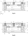
- FIG. 1A is a partial and schematic cross-sectional view of a passivated photodiode 1 belonging to a matrix of photodiodes, according to one embodiment.
- the photodiodes 1 are made from germanium. They are reverse biased from the side of the first surface 10a, and are optically isolated from each other by trenches filled with a doped semiconductor material.
- the photodiode 1 comprises a detection portion 10 extending along the axis Z between a first and a second reference surfaces, 10a and 10b, parallel to each other and opposite to each other.
- the first and second surfaces 10a, 10b are common to each photodiode 1 of the matrix.
- the first surface 10a is defined by the upper face of the first n+ doped region 11 and by a part of the upper face of the ferroelectric peripheral portion 26.
- the maximum thickness of the detection portion 10, defined according to the Z axis between the first and second surfaces 10a, 10b is here substantially constant from one photodiode to another, for example is between a few hundred nanometers and a few microns, for example between 1 ⁇ m and 5 ⁇ m approximately.
- the thickness is chosen so as to obtain good absorption in the range of wavelengths of the light radiation to be detected.
- the detection portion 10 has a transverse dimension in the XY plane which can be between a few hundred nanometers and a few tens of microns, for example between 1 ⁇ m and 20 ⁇ m approximately.
- the detection portion 10 is made of at least one crystalline semiconductor material, preferably monocrystalline. It is also produced on the basis of a chemical element of interest, here on the basis of germanium. By based on, it is meant that the crystalline semiconductor material corresponds to the chemical element of interest or is an alloy formed from at least the chemical element of interest.
- the chemical element of interest is advantageously germanium, so that the photodiodes are made of germanium Ge, silicon germanium SiGe, tin germanium GeSn, and silicon tin germanium SiGeSn.
- the detection portion 10 comes from at least one layer made of the same chemical element of interest, namely germanium here.
- It can thus be a layer or a substrate made of the same semiconductor material and have regions of different types of conductivity (homojunction) so as to form a PN or PIN junction. It can as a variant be a stack of sub-layers of different semiconductor materials (heterojunction), which are then formed based on the chemical element of interest.
- the detection portion 10 is thus formed of a first region 11 doped according to a first type of conductivity, here of type n, which is flush with the first surface 10a and forms an n+ doped well, and a second region 12 doped according to a second type of conductivity, here of type p, which is flush with the second surface 10b.
- An intermediate region 13 intrinsic in the case of a PIN junction
- doped according to the second type of conductivity in the case of a PN junction
- the semiconductor junction is of the PIN type, the first region 11 being doped with the n+ type, the second region 12 doped with the p+ type and the intermediate region 13 is intrinsic (not intentionally doped).
- the first n+ doped region 11 extends here from the first surface 10a and is surrounded by a ferroelectric peripheral portion 26.1 in the main plane, and possibly by the intermediate region 13. It is distant from the lateral edge 10c of the portion of detection 10 in the XY plane, the lateral border 10e being defined by the internal face of a peripheral semiconductor portion 25 doped p+. It thus forms an n+ doped well which is flush with the first surface 10a and is spaced apart by a non-zero distance with respect to the lateral edge 10c as well as the second surface 10b.
- the first n+ doped region 11 thus participates in delimiting the first surface 10a. It may have a doping that may be between 10 19 and 10 21 at/cm 3 approximately.
- the second region 12, here p+ doped extends in the XY plane flush with the second surface 10b, here from the side edge 10c. It extends along the Z axis from the second surface 10b. It may have a substantially uniform thickness along the Z axis and thus only be flush with a lower zone of the side edge 10c.
- the second p+-doped region 12 may have a p+-doped lateral region 14 which is continuously flush with the lateral border 10c along the Z axis and extends over the entire periphery of the detection portion 10.
- the second p+-doped region 12 may have a doping which can be between 10 18 and 10 20 at/cm 3 approximately.
- the intermediate region 13 is located between the two regions 11, 12 doped n+ and p+. It can surround the first n+ doped region 11 in the XY plane, and is separated from the first surface 10a and therefore from the dielectric layer 30 by the ferroelectric peripheral portion 26.1. It is here made of an intrinsic semiconductor material so as to form a PIN junction but can be doped according to the second type of conductivity, for example p type, to form a PN junction (cf. fig. 1B ).
- the photodiode 1 here comprises a lower insulating layer 21, made of a dielectric material, covering the second surface 10b of the detection portion 10, as well as, as described later, the lower face of the peripheral portion p+ doped semiconductor 25.
- the lower insulating layer 21 can also be adapted to form an antireflection function vis-à-vis the incident light radiation. It in fact forms the face for receiving the light radiation intended to be detected.
- the detection portion 10 of the photodiode 1 is here delimited laterally, in the XY plane, by a trench, preferably continuous, filled with a semiconductor material doped according to the second type of conductivity (here of type p), and forming a semiconductor peripheral portion 25, here p+ doped.
- the peripheral crossing portion 25 participates in electrically biasing the photodiode 1, here from the side of the first surface 10a, and in pixelizing the matrix of photodiodes (optical insulation). It extends here over the entire thickness of the detection portion 10 to lead to the lower insulating layer 21, but alternatively, it may not lead to the lower insulating layer 21 and may end in the second region 12 doped p+.
- the inner face of this p+ doped semiconductor peripheral portion 25 then defines the lateral edge 10c of the detection portion 10.
- the semiconductor material is preferably made from silicon, for example amorphous silicon, polycrystalline silicon, germanium silicon, or even can be made of amorphous germanium.
- the dielectric layer 30 covers the first surface 10a of the photodiode 1, and makes it possible to electrically insulate the contacts 31.1 and 31.2. It is thus in contact with the first n+ doped region 11 as well as with the ferroelectric peripheral portion 26.1.
- It is made of a dielectric material, such as a silicon oxide, a silicon nitride, or a silicon oxynitride. Other dielectric materials can be used, such as a hafnium or aluminum oxide, or even an aluminum nitride, among others. It has a thickness for example comprised between 50 nm and 500 nm.
- the passivation deposition technique used can participate in generating a surface contribution of the dark current when it rests on and in contact with the intermediate region 13.
- the dielectric layer can induce the formation of a depleted zone in the intermediate region 13 from the first surface 10a.
- this depleted zone is located in the space charge zone of photodiode 1, it can then be the site of a parasitic generation-recombination current.
- such a dielectric layer can form an inversion zone, then electrically conductive, which can therefore connect the first region 11 doped n+ to the peripheral semiconductor portion doped p+.
- each photodiode 1 comprises a peripheral portion 26.1 made of a ferroelectric material, located between and in contact with the intermediate region 13 and the dielectric layer 30, and located between the first region 11 doped n + and the peripheral semiconductor portion 25 surrounding the first n+ doped region 11 in the XY plane.
- the ferroelectric peripheral portion 26.1 is thus in contact with the layer dielectric 30 on an upper face, and in contact with the intermediate region 13 on its lower face.
- the ferroelectric peripheral region 26.1 extends around the first n+ doped region 11 in the main plane, in a continuous or optionally discontinuous manner.
- the ferroelectric peripheral region 26.1 thus extends along the Z axis from the first surface 10a, and surrounds the first n+ doped region 11 in the XY plane. It is located here in contact with the first n+ doped region 11 (zero spacing), in particular when the doping element of the first n+ doped region 11 is phosphorus, which tends to diffuse rapidly, but as a variant may not be at the contact of the latter (non-zero spacing). It is also located in contact with the p+ doped semiconductor peripheral portion (zero spacing), but as a variant may not be in contact with the latter (non-zero spacing).
- a ferroelectric material has a spontaneous electric polarization (or electric dipole moment) which can be oriented by the application of an external electric field, here by the electric field generated between the first region 11 doped n+ and the peripheral semiconductor region 25 doped p+ when the photodiode is biased (reverse).
- the ferroelectric peripheral region 26.1 can be made of a material chosen from oxides of perovskite structure, such as for example PZT Pb(Zr,Ti)O 3 , PLZT (Pb,La)(Zr,Ti)O 3 , BT BaTiO 3 , PT PbTiO 3 , PLT (Pb,La)TiO 3 , poly(vinylidene fluoride) (PVDF), as well as among HfO 3 , ZnO, AlN, among others, and mixtures thereof.
- the ferroelectric material is preferably chosen from PZT, BT, PVDF, HfO 2 , ZnO, AlN, for reasons in particular of ease of use in the method of manufacturing such a photodiode.
- the polarization of the photodiode 1 makes it possible to orient the ferroelectric dipoles present in the peripheral ferroelectric region 26.1 along a privileged direction, for example a radial direction in the XY plane or a vertical direction along the Z axis.
- a privileged direction for example a radial direction in the XY plane or a vertical direction along the Z axis.
- the orientation of the ferroelectric dipoles in this peripheral ferroelectric region 26.1 makes it possible to block the passage of charge carriers between the first region 11 doped n+ and the peripheral semiconductor portion 25 doped p+ under the dielectric layer 30, in this same peripheral region.
- ferroelectric 26.1 It therefore performs a function of lateral electrical insulation between the first region 11 doped n+ and the peripheral semiconductor portion 25 doped p+ at the level of the first surface 10a, thus reducing the risks of short-circuit between these parts of the photodiode 1 due to for example from the area of inversion. This reduces the surface components of the dark current, which makes it possible to improve the performance of the photodiode.
- this ferroelectric peripheral region 26.1 allows the lateral spacing between the first n+ doped region 11 and the p+ doped semiconductor peripheral portion 25 to be reduced, thus improving the performance of the photodiode 1. This avoids the situation where , in the absence of such a ferroelectric peripheral region 26.1, the carriers photogenerated in the intermediate region 13 close to the first surface 10a are not collected due to an insufficient quality of the passivation of this first surface 10a.
- the detection portion 10 advantageously comprises a lateral region 14 doped according to the second type of conductivity, here of p+ type, located at the level of the lateral border 10c.
- This lateral region 14 has a higher doping level than that of the intermediate region 13 when it is doped.
- the lateral region 14 doped p+ is flush with the lateral edge 10c and is in contact with the peripheral semiconductor portion 25 doped p+.
- the biasing of the second region 12 doped p+ is improved insofar as the contact surface with the peripheral semiconductor portion 25 doped p+ is increased.
- this p+ doped lateral region 14 makes it possible to prevent the space charge zone of the photodiode 1 from extending as far as the lateral edge 10c.
- the contribution of this zone (potentially not free from defects linked to the production of the trenches) to the dark current is limited. This improves the performance of the photodiode 1.
- the detection portion 10 is made from germanium, for example from germanium, and the p+ doped semiconductor peripheral portion 25 is made from silicon, for example from doped polysilicon.
- the detection portion 10 then advantageously comprises a lateral zone 15 made from silicon germanium.
- the lateral zone 15 is flush with the lateral border 10c and is in contact with the peripheral semiconductor portion 25 doped p+.
- the lateral zone 15 has a forbidden band energy (gap) greater than that of the detection portion 10 made of germanium.
- This lateral “gap opening” makes it possible to reduce the sensitivity of the photodiode 1 to the faults present near the trenches. This also improves the performance of the photodiode 1.
- the photodiode 1 further comprises an electrical circuit making it possible to reverse bias it.
- the electric circuit makes it possible to polarize the photodiode 1 from the side of the first surface 10a.
- the electrical circuit may comprise contact metallizations 31.1, 31.2 extending through through openings of the dielectric layer 30 and coming into contact respectively with the first region 11 doped n+ and the peripheral semiconductor portion 25 doped p+.
- the photodiode 1 is intended to be reverse biased, for example by applying a negative electric potential to the p+ doped semiconductor peripheral portion 25 and bringing the first n+ doped region 11 to ground.
- the fig. 1A illustrates a first so-called lateral electrical blocking configuration, in which the ferroelectric dipoles are oriented, when the photodiode is reverse biased, substantially parallel to the XY plane, in a radial direction going from the first n+ doped region 11 towards the peripheral portion p+ doped semiconductor 25.
- the reverse biasing of the photodiode generates an electric field E between the first region 11 doped n+ and the peripheral semiconductor portion 25 doped p+, which orients the ferroelectric dipoles along said radial direction in the XY plane.
- this configuration makes it possible in particular to block the passage of charge carriers at the level of the first surface 10a, in the ferroelectric peripheral portion 26.1, thus reducing the surface component of the dark current.
- FIG. 1B is a schematic and partial view of a photodiode according to a variant of the embodiment illustrated in the fig. 1A , illustrating a second electrical blocking configuration, here called vertical.
- the photodiode 1 comprises at least one peripheral planar electrode 32.2, arranged in contact of a peripheral contact metallization 31.2, and extending in an XY plane facing, that is to say vertically, the ferroelectric peripheral portion 26.1, and optionally facing at least part of the first portion 11 n+ doped.
- the peripheral contact metallization 31.2 is that which comes into contact with the peripheral semiconductor portion 25 doped p+.
- the reverse biasing of the photodiode 1 for example by applying a negative electric potential to the peripheral p+ doped semiconductor portion 25 and bringing the first n+ doped portion 11 to ground, generates an electric field E between the first region 11 n+ doped on the one hand, and on the other hand the peripheral planar electrode 32.2 and the second p+ doped region 12 on the other hand, which orients the ferroelectric dipoles along the Z axis.
- the vertical component (along the axis Z) of the electric field E at the ferroelectric peripheral portion 26.1 predominates over the component horizontal (in the XY plane) due to the large surface of the peripheral planar electrode 32.2 which faces the ferroelectric peripheral portion 26.1 (and possibly part of the first n+ doped portion 11).
- this configuration makes it possible to reduce the risk of formation of a depletion zone or even of an inversion zone under the dielectric layer 30 in the intermediate region 13, thus reducing the surface component of the dark current.
- the peripheral planar electrode 32.2 makes it possible to reflect the initially unabsorbed detection electromagnetic radiation, and therefore makes it possible to increase the sensitivity of the photodiode.
- the photodiode 1 can have dimensions in the XY plane of between approximately 1 ⁇ m and 100 ⁇ m.
- the thickness of the second p+ doped region 12 can be between approximately 20 nm and 500 nm.
- the thickness of the intrinsic region 13 can be between 0.7 ⁇ m and 2.5 ⁇ m approximately when the photodiode 1 is intended to detect light radiation in the SWIR or near infrared (NIR) range.
- the first n+ doped region 11 may have a thickness of between 10 nm and 600 nm approximately.
- the dielectric layer 30 may have a thickness making it possible to entirely cover the upper face of the photodiode 1 and for example comprised between 10 nm and 600 nm approximately, and the thickness of the lower insulating layer 21 may be comprised between 50 nm and 1 ⁇ m approximately.
- the photodiodes 1 are made of germanium and include a PIN junction, and are suitable for detecting infrared radiation in the SWIR range.
- Photodiodes 1 are planar and passivated, and are reverse biased from first surface 10a by a driver chip hybridized to the photodiode array.
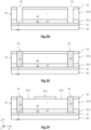
- a first semiconductor sub-layer 22.1 of monocrystalline germanium is produced.
- the first semiconductor sub-layer 22.1 is secured to a support layer 20, here in silicon, via a lower insulating layer 21, here in a silicon oxide.
- This stack takes the form of a GeOI (for Germanium On Insulator ) substrate.
- This stacking is preferably carried out by means of the method described in the publication of Reboud et al. titled Structural and optical properties of 200mm germanium-on-insulator (GeOI) substrates for silicon photonics applications, Proc. SPIE 9367, Silicon Photonics X, 936714 (February 27, 2015 ).
- Such a method has the advantage of producing a germanium 22.1 semiconducting sub-layer exhibiting a total absence or a low rate of structural defects such as dislocations.
- the germanium can be unintentionally doped or be doped, for example p-type.
- Semiconductor sub-layer 22.1 may have a thickness between approximately 100 nm and 500 nm, for example equal to approximately 300 nm, and may be covered with a protective layer (not shown) of silicon oxide.
- the lower insulating layer 21 (BOX, for Buried Oxide , in English) can have a thickness comprised between 50 nm and 1 ⁇ m, for example comprised between 100 nm and 500 nm, and advantageously performs an antireflection function.
- the first germanium sub-layer 22.1 is then doped according to the second type of conductivity, here of p-type, by ion implantation of a dopant such as boron or gallium, when the first sub-layer 22.1 was initially in intrinsic germanium.
- the protective layer if any, has been removed beforehand by surface cleaning, and the first sub-layer 22.1 of germanium can be coated with a layer of preimplantation oxide (not shown) with a thickness of a few tens of nanometers, for example equal to 20 nm.
- the germanium sub-layer 22.1 then has a doping level of between approximately 10 18 and 10 20 at/cm 3 .
- Diffusion annealing of the dopant can then be carried out under nitrogen, for a few minutes to a few hours, for example 1 hour, at a temperature which can be between 600° C. and 800° C., for example equal to 800° C. This annealing may not be carried out when the sub-layer 22.1 was growth-doped.
- Another way of fabricating this p+ layer is by epitaxy of a boron-doped germanium layer in situ between 10 18 and 10 20 at/cm 3 approximately on a sub-layer of intrinsic germanium. This epitaxy can be done between 400 and 800°C but preferably at 400°C.
- a second semiconductor sub-layer 22.2 of germanium is produced by epitaxy from the first sub-layer 22.1.
- the two sub-layers 22.1, 22.2 are intended to form the coplanar germanium detection portions 10 of the photodiode matrix 1.
- the second sub-layer 22.2 is formed by epitaxy, for example by chemical vapor deposition (CVD, for Chemical Vapor Deposition , in English) and reduced pressure precedence (RPCVD, for Reduced Pressure Chemical Vapor Deposition ) or by any other epitaxy technique. Annealing can be carried out to reduce the rate of dislocations in the sub-layer 22.2.
- the pre-implementation oxide layer, if present, has been previously removed by surface cleaning.
- the second sub-layer 22.2 of germanium is here intrinsic, that is to say not intentionally doped insofar as it is desired to produce a PIN junction. It is intended to form the light absorption zone of the photodiodes 1. Its thickness depends on the range of wavelengths of the light radiation to be detected in the case of a photodiode 1. In the context of SWIR photodiodes, the sub- layer 22.2 of intrinsic germanium has a thickness for example comprised between 0.5 ⁇ m and 3 ⁇ m, preferably equal to 1.5 ⁇ m.
- an upper insulating layer 23 is deposited so as to continuously cover the upper face of the second sub-layer 22.2, that is to say so as to cover the detection portions 10 of the photodiodes 1.
- the upper insulating layer 23 is made of a dielectric material, for example an oxide, a nitride or a silicon oxynitride. A cleaning of the upper face of the second sub-layer 22.2 may have been carried out beforehand.
- the upper insulating layer 23 may have a thickness of between 10 nm and 600 nm.
- the trenches 24 intended to pixelate the photodiodes 1 and participate in electrically reverse biasing them are produced by photolithography and etching. This produces a localized etching of the upper insulating layer 23, of the sub-layer 22.2 of intrinsic germanium, and of the sub-layer 22.1 of p+-doped germanium, until it emerges here on the upper face of the lower insulating layer 21 (but the trenches 24 can lead to the sub-layer 22.1 without crossing it).
- Each trench 24 thus preferably extends continuously around a photodiode 1.
- a plurality of detection portions 10 are thus obtained, separated from each other by a continuous trench 24.
- the trenches 24 have a transverse dimension (width) in the XY plane which can be between 300 nm and 2 ⁇ m, for example equal to 1 ⁇ m.
- the detection portions 10 can thus have a shape in the XY plane, for example circular, oval, polygonal, for example square, or any other shape.
- the semiconductor peripheral portions 25 are then produced.
- a doped semiconductor material is deposited so as to fill the trenches 24.
- the semiconductor material is preferably a silicon-based material, for example amorphous silicon, polycrystalline silicon, silicon germanium, or even amorphous germanium.
- the semiconductor material is doped according to the second type of conductivity, here of type p with boron or gallium, with a concentration of dopants of the order of 10 19 to 10 20 at/cm 3 approximately.
- the doped semiconductor material comes into contact with the lateral edge 10c via the trench 24.
- a chemical mechanical polishing (CMP) step is then carried out, with a stop on the upper face of the upper insulating layer 23, to eliminate the semiconductor material in excess and planarize the upper face formed by the upper insulating layer 23 and the semiconductor material of the peripheral semiconductor portion 25.
- CMP chemical mechanical polishing
- peripheral openings 23.2 are made, by photolithography and etching, in the upper insulating layer 23, which pass through to emerge on the upper face of the intrinsic sub-layer 22.2.
- the peripheral opening 23.2 surrounds in the XY plane a central portion 23.1 of the upper insulating layer 23 intended for the subsequent production of the first region 11 doped n+.
- the peripheral opening 23.2 has a radial dimension in the XY plane, starting from the central portion 21.1, which will subsequently define the radial dimension of the ferroelectric peripheral portion 26.1. This radial dimension depends on the size of the photodiode 1. It can be between 100 nm and a few microns.
- the peripheral opening 23.2 extends radially in the XY plane until it opens onto the internal edge of the p-doped semiconductor peripheral portion 25, but as a variant it may not open onto the p-doped semiconductor peripheral portion 25 and thus remained delimited in the XY plane by the upper insulating layer 23.
- a peripheral notch 27 is produced by etching in the sub-layer 22.2 of the intrinsic germanium, of the same radial dimension as the peripheral opening 23.2, and of a depth which advantageously depends on the desired thickness of the first region 11 doped n+ (this depth will make it possible to avoid excessive lateral diffusion of the dopants, during the step of producing the first region 11 doped n+).
- This depth can be between 50 nm and 600 nm, for example equal to 200 nm. It is then possible to carry out a surface cleaning of the sub-layer 22.2 of the intrinsic germanium.
- the intermediate region 13 then has a projecting part 13.1 in the direction +Z, surrounded by the peripheral notch 27 in the XY plane, and covered by the central portion 23.1 of the upper insulating layer 23.
- a layer 26 made of a ferroelectric material is deposited, so as to fill the peripheral indentations 27.
- This ferroelectric layer 26 has a thickness at least equal to the depth of the peripheral indentations 27. It therefore continuously covers the upper insulating layer 23 (in particular the central portion 23.1) and the upper face of the peripheral semiconductor portion 25, as well as the free surface of the sub-layer 22.2 of the germanium in the peripheral notches 27.
- the ferroelectric peripheral portion 26.1 is the part of the layer 26 which is located in the peripheral notch 27, in contact with the germanium of the sub-layer 22.2 (therefore of the intermediate region 13). It surrounds in the XY plane the projecting part 13.1 of the intermediate region 13.
- crystallization annealing of the ferroelectric material is then carried out, for example at a temperature of between 500° C. and 750° C. for 5 to 30 min.
- This annealing also allows the formation of the side regions 14 doped p+ by diffusion of the doping elements from the peripheral semiconductor portions 25 doped p+ towards the intermediate region 13.
- the side zone 15 with gap opening is formed by interdiffusion between the germanium of the detection portion 10 and the silicon of the peripheral semiconductor portion 25.
- a mask 28 of photoresist is deposited in order to produce the first portion 11 doped n+.
- This mask 28 has an opening 28.1 intended for the implantation of n-type dopants in the germanium of the intermediate region 13.
- the part of the ferroelectric layer 26 located at the level of this implantation opening 28.1 is etched, so as to free a surface of the central portion 23.1 of the upper insulating layer 23.
- n-type doping elements for example phosphorus, arsenic or antimony (or a combination of these elements)
- concentration of the doping elements can be between 10 19 and 10 21 at/cm 3 .
- diffusion and activation annealing of the doping elements having been implanted is carried out, at a temperature for example comprised between 550° C. and 700° C. for a duration of 5 s to 30 s.
- the implantation depth of the doping elements is less than the thickness of the ferroelectric layer 26, the latter then makes it possible to block the lateral diffusion of the doping elements in the direction of the peripheral semiconductor portion 25 doped p+.
- a first n+-doped region 11 having the desired lateral dimensions is obtained, and the risks of a short-circuit between this first n+-doped region 11 and the p+-doped semiconductor peripheral portion 25 are limited.
- the layer 28 of photoresist is also removed.
- the central portion 23.1 of the upper insulating layer 23 is removed, so as to free the upper face of the detection portion 10, corresponding here to that of the first region 11 doped n+.
- the parts of the ferroelectric layer 26 which were in contact with the central portion are also removed.
- the upper surface of the first n+ doped region 11 can then be cleaned.
- the upper face of the ferroelectric peripheral portion 26.1 and the upper face of the first n+ doped region 11 are here coplanar. They together define the first surface 10a, which is opposed to the second surface 10b.
- the dielectric layer 30 is deposited so as to cover the optoelectronic stack thus produced on the side of the first surface 10a.
- This dielectric layer 30 thus extends over and in contact with the ferroelectric layer 26 and the first region 11 doped n+.
- It is made of a dielectric material, for example an oxide, nitride or oxynitride of silicon, an oxide or nitride of aluminum, a hafnium oxide, among others. It may have a thickness for example of between 10 nm and 600 nm.
- contact metallizations 31 are produced, extending through the dielectric layer 30, and coming into contact with the first region 11 doped n+ (for the central metallization 31.1) and in contact with the peripheral semiconductor portion 25 doped p+ ( for the lateral metallization 31.2).
- the contact metallizations 31 can be produced in the conventional manner, by filling the openings passing through the dielectric layer 30 with at least one metallic material (barrier layer based on Ti, core in copper), followed by a CMP planarization step.
- the dielectric layer 30 and the contact metallizations 31 together present the same coplanar upper face.
- the hybridization of the optoelectronic stack thus obtained is carried out on a control chip 40.
- the connection face of the control chip 40 can thus be coated with an insulating layer 41, made of a dielectric material, crossed by metallizations 42.
- the optoelectronic stack and the control chip 40 are thus assembled by hybrid molecular adhesion, by contact of the faces formed by the contact metallizations 31, 42 and the insulating layers 30, 41. to increase the surface bonding energy between the two faces in contact.
- the support layer 20 is then removed, for example by abrasion ( grinding , in English), so as to expose the lower insulating layer 21. This thus forms the face receiving the light radiation to be detected, and advantageously ensures an anti-reflective function.
- the manufacturing method thus makes it possible to obtain one or more passivated photodiodes 1, each comprising a peripheral ferroelectric portion 26.1 surrounding the first n+ doped region 11 in the XY plane, and located between and in contact with the dielectric layer 30 and the region intermediate 13.
- a ferroelectric peripheral portion 26.1 when the photodiode 1 is biased, makes it possible to orient the ferroelectric dipoles horizontally, which makes it possible to reduce the surface component of the dark current, and therefore improve the performance of the photodiode 1.
- the photodiode 1 comprises planar electrodes making it possible to orient the ferroelectric dipoles in a vertical direction.
- the optoelectronic stack obtained during step 2N was considered here.
- planar electrodes 32 are produced which come into contact with the metallizations 31, for example based on Ti/TiN, and having a thickness of the order of approximately 10 to 40 nm.
- a peripheral electrode 32.2 is produced which comes into contact with the peripheral metallization 31.2 and extends in the XY plane on the dielectric layer 30 so as to face (vertically) the ferroelectric peripheral portion 26.1 and here a part of the first n+ doped region 11.
- a central electrode 32.1 is also produced which comes into contact with the central metallization 31.1.
- a second upper insulating layer 33 is deposited, so as to cover the dielectric layer 30 and the planar electrodes 32.1 and 32.2. Second contact metallizations 34.1, 34.2 are made through insulating layer 33.
- hybridization of the optoelectronic stack thus obtained is carried out on the control chip 40.
- the optoelectronic stack and the control chip 40 are here assembled by hybrid molecular adhesion, by contact of the faces formed of the contact metallizations 34, 42 and insulating layers 33, 41.
- the support layer 20 is then removed, for example by grinding , so as to expose the lower insulating layer 21.
- the manufacturing method thus makes it possible to obtain one or more passivated photodiodes 1, each comprising a ferroelectric peripheral portion 26.1 surrounding the first n+-doped region 11 and located at the level of the first surface 10a, therefore in contact with the dielectric layer 30.
- the presence of such a ferroelectric peripheral portion 26.1, when the photodiode 1 is biased, due to the planar electrode 32.2 makes it possible to orient the ferroelectric dipoles vertically, which makes it possible to reduce the surface component of the dark current, and therefore improve the performance of the photodiode 1.
Landscapes
- Light Receiving Elements (AREA)
- Engineering & Computer Science (AREA)
- Manufacturing & Machinery (AREA)
Claims (14)
- Fotodiode (1), die eine erste Oberfläche (10a) und eine zweite Oberfläche (10b) aufweist, die einander gegenüberliegen und zu einer Hauptebene parallel sind, umfassend:o einen Detektionsabschnitt (10), der aus einem Halbleitermaterial hergestellt ist, umfassend:• eine erste Region (11), die gemäß einem ersten Leitfähigkeitstyp dotiert ist und an die erste Oberfläche (10a) angrenzt und dazu bestimmt ist, elektrisch polarisiert zu werden;• eine zweite Region (12), die gemäß einem zweiten Leitfähigkeitstyp, der zu dem ersten Typ entgegengesetzt ist, dotiert ist und an die zweite Oberfläche (10b) angrenzt;• eine Zwischenregion (13), die sich zwischen der ersten Region (11) und der zweiten Region (12) befindet;o eine dielektrische Schicht (30), die den Detektionsabschnitt (10) auf der ersten Oberfläche (10a) abdeckt und mit der ersten Region (11) in Kontakt kommt;o einen Halbleiterumfangsabschnitt (25), der aus einem gemäß dem zweiten Leitfähigkeitstyp dotierten Halbleitermaterial hergestellt ist und dazu bestimmt ist, elektrisch polarisiert zu werden, und der den Detektionsabschnitt (10) in der Hauptebene umgibt und mit der zweiten Region (12) in Kontakt kommt;o dadurch gekennzeichnet, dass sie Folgendes umfasst:o einen ferroelektrischen Umfangsabschnitt (26.1), der aus einem ferroelektrischen Material hergestellt ist,• der sich zwischen der Zwischenregion (13) und der dielektrischen Schicht (30) befindet und mit diesen in Kontakt ist und• der sich zwischen der ersten Region (11) und dem Halbleiterumfangsabschnitt (25) befindet und die erste Region (11) in der Hauptebene umgibt.
- Fotodiode (1) nach Anspruch 1, wobei der ferroelektrische Umfangsabschnitt (26.1) einerseits mit der ersten Region (11) und andererseits mit dem Halbleiterumfangsabschnitt (25) seitlich in Kontakt ist.
- Fotodiode (1) nach Anspruch 1 oder 2, wobei der Detektionsabschnitt (10) eine Umfangsaussparung (27) aufweist, die einen Vorsprung (13.1) begrenzt, der in der Hauptebene von dem ferroelektrischen Umfangsabschnitt (26.1) umgeben ist.
- Fotodiode (1) nach einem beliebigen der Ansprüche 1 bis 3, wobei der Detektionsabschnitt (10) auf Basis von Germanium hergestellt ist und der Halbleiterumfangsabschnitt (25) auf Basis von Silizium hergestellt ist.
- Fotodiode (1) nach einem beliebigen der Ansprüche 1 bis 4, wobei der ferroelektrische Umfangsabschnitt (26.1) auf Basis eines Materials hergestellt ist, das aus PZT, PLZT, BT, PT, PLT, PVDF sowie aus HfO2, ZnO und AIN ausgewählt ist.
- Fotodiode (1) nach einem beliebigen der Ansprüche 1 bis 5, wobei die dielektrische Schicht (30) von einer mittigen Metallisierung (31.1), die die erste Region (11) kontaktiert, und von einer seitlichen Metallisierung (31.2), die den Halbleiterumfangsabschnitt (25) kontaktiert, durchquert wird.
- Fotodiode (1) nach Anspruch 6, die eine Umfangselektrode (32.2) umfasst, die sich auf der dielektrischen Schicht (30) und in Kontakt mit der seitlichen Metallisierung (31.2) erstreckt, die erste Region (11) umgibt und sich senkrecht zu dem ferroelektrischen Umfangsabschnitt (26.1) befindet.
- Fotodiodenmatrix (1), die eine Vielzahl von Fotodioden (1) nach einem beliebigen der Ansprüche 1 bis 7 umfasst, wobei obere Flächen der ersten Regionen (11), die zu den zweiten Regionen (12) entgegengesetzt sind, koplanar sind und die zweiten Oberflächen (10b) koplanar sind.
- Optoelektronische Vorrichtung, die eine Fotodiodenmatrix (1) nach Anspruch 8 und einen Steuerchip umfasst, der an die Fotodiodenmatrix hybridisiert ist und dazu angepasst ist, die Fotodioden umgekehrt zu polarisieren.
- Verfahren zur Fertigung einer Fotodiode (1) nach einem beliebigen der Ansprüche 1 bis 7, das die folgenden Schritte umfasst:o Herstellen eines Stapels, der eine erste Unterschicht (22.1) umfasst, die auf den zweiten Leitfähigkeitstyp dotiert ist und dazu bestimmt ist, die zweite Region (12) zu bilden, und die von einer zweiten Unterschicht (22.2) abgedeckt wird, die dazu bestimmt ist, die Zwischenregion (13) zu bilden;o Abscheiden einer oberen Isolierschicht (23) auf die zweite Unterschicht (22.2);o Herstellen des Halbleiterumfangsabschnitts (25), der sich durch die obere Isolierschicht (23) und die zweite Unterschicht (22.2) erstreckt, bis er an der ersten Unterschicht (22.1) mündet;o Herstellen einer Umfangsaussparung (27) in der zweiten Unterschicht (22.2) durch eine Umfangsöffnung (23.2) hindurch, die einen mittigen Abschnitt (23.1) der oberen Isolierschicht (23) umgibt;o Herstellen des ferroelektrischen Umfangsabschnitts (26.1), der die Umfangsaussparung (27) ausfüllt;o Entfernen des mittigen Abschnitts (23.1);o Herstellen der ersten Region (11) in der zweiten Unterschicht (22.2);o Abscheiden der dielektrischen Schicht (30) auf den ferroelektrischen Umfangsabschnitt (26.1) und die erste Region (11) und diese kontaktierend.
- Fertigungsverfahren nach Anspruch 10, das einen Schritt des Rekristallisationsglühens des Materials des ferroelektrischen Umfangsabschnitts (26.1) umfasst, was ferner ein Diffundieren der Dotierungselemente von dem Halbleiterumfangsabschnitt (25) in den Diffusionsabschnitt (10) sicherstellt, sodass in dem Detektionsabschnitt (10) eine seitliche Region (14) gebildet wird, die gemäß dem zweiten Leitfähigkeitstyp dotiert ist.
- Fertigungsverfahren nach Anspruch 11, wobei der Detektionsabschnitt (10) auf Basis von Germanium hergestellt ist und der Halbleiterumfangsabschnitt (25) auf Basis von Silizium hergestellt ist, wobei das Rekristallisationsglühen ferner ein Diffundieren des Siliziums des Halbleiterumfangsabschnitts (25) in den Detektionsabschnitt (10) sicherstellt, sodass ein seitlicher Bereich (15), der auf Basis von Silizium-Germanium hergestellt ist, gebildet wird.
- Fertigungsverfahren nach einem beliebigen der Ansprüche 10 bis 12, wobei der Schritt des Herstellens der ersten Region (11) das Implantieren von Dotierungselementen in die zweite Unterschicht (22.2) durch den mittigen Abschnitt (23.1) hindurch umfasst.
- Fertigungsverfahren nach Anspruch 13, wobei die Implantierungstiefe geringer als die Dicke des ferroelektrischen Umfangsabschnitts (26.1) ist, der seitlich mit einem Vorsprung (13.1) der zweiten Unterschicht (22.2), der durch die Umfangsaussparung (27) begrenzt wird, in Kontakt ist, und umfassend ein Aktivierungsglühen der Dotierungselemente, wobei der ferroelektrische Umfangsabschnitt (26.1) während dieses Glühens eine seitliche Sperre für das Diffundieren der Dotierungselemente sicherstellt.
Applications Claiming Priority (1)
| Application Number | Priority Date | Filing Date | Title |
|---|---|---|---|
| FR2009529A FR3114440B1 (fr) | 2020-09-21 | 2020-09-21 | Photodiode passivée comportant une portion périphérique ferroélectrique |
Publications (2)
| Publication Number | Publication Date |
|---|---|
| EP3971995A1 EP3971995A1 (de) | 2022-03-23 |
| EP3971995B1 true EP3971995B1 (de) | 2023-07-12 |
Family
ID=74125357
Family Applications (1)
| Application Number | Title | Priority Date | Filing Date |
|---|---|---|---|
| EP21197570.1A Active EP3971995B1 (de) | 2020-09-21 | 2021-09-17 | Passivierte fotodiode mit einem ferroelektrischen peripheren teil |
Country Status (4)
| Country | Link |
|---|---|
| US (2) | US12382732B2 (de) |
| EP (1) | EP3971995B1 (de) |
| CN (1) | CN114256360A (de) |
| FR (1) | FR3114440B1 (de) |
Families Citing this family (5)
| Publication number | Priority date | Publication date | Assignee | Title |
|---|---|---|---|---|
| FR3101727B1 (fr) * | 2019-10-08 | 2021-09-17 | Commissariat Energie Atomique | procede de fabrication d’au moins une photodiode planaire contrainte en tension |
| FR3114440B1 (fr) * | 2020-09-21 | 2022-08-19 | Commissariat Energie Atomique | Photodiode passivée comportant une portion périphérique ferroélectrique |
| FR3140992B1 (fr) | 2022-10-14 | 2024-10-04 | Commissariat Energie Atomique | Photodiode planaire à base de germanium comportant une zone latérale périphérique en compression |
| TWI831452B (zh) * | 2022-11-01 | 2024-02-01 | 大陸商北京集創北方科技股份有限公司 | 吸收波長可調之感光元件、圖像採集裝置以及資訊處理裝置 |
| CN116314430B (zh) * | 2023-04-14 | 2025-12-16 | 西安电子科技大学杭州研究院 | 基于异质结的铁电电容型光电探测器件及其制备和应用 |
Family Cites Families (28)
| Publication number | Priority date | Publication date | Assignee | Title |
|---|---|---|---|---|
| US5073010A (en) * | 1990-05-11 | 1991-12-17 | University Of Colorado Foundation, Inc. | Optically addressable spatial light modulator having a distorted helix ferroelectric liquid crystal member |
| EP1634323A4 (de) * | 2003-06-13 | 2008-06-04 | Univ North Carolina State | Komplexe oxide zur verwendung in halbleiterbauelementen und diesbezügliche verfahren |
| US7397101B1 (en) * | 2004-07-08 | 2008-07-08 | Luxtera, Inc. | Germanium silicon heterostructure photodetectors |
| KR100664376B1 (ko) * | 2004-12-29 | 2007-01-02 | 동부일렉트로닉스 주식회사 | 반도체 소자의 커패시터 제조 방법 |
| FR2892230B1 (fr) * | 2005-10-19 | 2008-07-04 | Soitec Silicon On Insulator | Traitement d'une couche de germamium |
| US20070170536A1 (en) * | 2006-01-25 | 2007-07-26 | Sharp Laboratories Of America, Inc. | Liquid phase epitaxial GOI photodiode with buried high resistivity germanium layer |
| JP2009033043A (ja) * | 2007-07-30 | 2009-02-12 | Panasonic Corp | 光半導体装置 |
| WO2010083263A1 (en) * | 2009-01-15 | 2010-07-22 | Jie Yao | Mesa heterojunction phototransistor and method for making same |
| JP2010278045A (ja) * | 2009-05-26 | 2010-12-09 | Panasonic Corp | 光半導体装置 |
| IT1399690B1 (it) * | 2010-03-30 | 2013-04-26 | St Microelectronics Srl | Fotodiodo a valanga operante in modalita' geiger ad elevato rapporto segnale rumore e relativo procedimento di fabbricazione |
| US9941319B2 (en) * | 2010-10-13 | 2018-04-10 | Monolithic 3D Inc. | Semiconductor and optoelectronic methods and devices |
| US20140048897A1 (en) * | 2012-08-16 | 2014-02-20 | Omnivision Technologies, Inc. | Pixel with negatively-charged shallow trench isolation (sti) liner |
| WO2015015700A1 (ja) * | 2013-08-02 | 2015-02-05 | シャープ株式会社 | 放射線検出用半導体装置 |
| FR3041817B1 (fr) * | 2015-09-30 | 2017-10-13 | Commissariat Energie Atomique | Photodiode de type spad |
| ITUA20164571A1 (it) * | 2016-06-21 | 2017-12-21 | St Microelectronics Srl | Dispositivo optoelettronico multibanda per applicazioni colorimetriche e relativo metodo di fabbricazione |
| EP3486954B1 (de) * | 2016-07-12 | 2021-07-14 | Mitsubishi Electric Corporation | Detektor für elektromagnetische wellen und detektoranordnung für elektromagnetische wellen |
| US10497818B2 (en) * | 2016-07-29 | 2019-12-03 | Canon Kabushiki Kaisha | Photodetection device and photodetection system |
| US10297708B1 (en) * | 2018-01-25 | 2019-05-21 | The United States Of America, As Represented By The Secretary Of The Air Force | Surface passivation for PhotoDetector applications |
| FR3080489B1 (fr) * | 2018-04-18 | 2020-05-08 | Commissariat A L'energie Atomique Et Aux Energies Alternatives | Dispositif optoelectronique a diode contrainte en tension par effet piezoelectrique inverse |
| US11018168B2 (en) * | 2018-09-20 | 2021-05-25 | Taiwan Semiconductor Manufacturing Co., Ltd. | Image sensor with improved timing resolution and photon detection probability |
| FR3089062A1 (fr) * | 2018-11-23 | 2020-05-29 | Commissariat A L'energie Atomique Et Aux Energies Alternatives | procede de fabrication d’au moins une photodiode planaire passivee a courant d’obscurité reduit |
| FR3089348B1 (fr) | 2018-11-30 | 2020-10-30 | Commissariat Energie Atomique | procede de fabrication d’une matrice de diodes a base de germanium et a faible courant d’obscurité |
| FR3101727B1 (fr) * | 2019-10-08 | 2021-09-17 | Commissariat Energie Atomique | procede de fabrication d’au moins une photodiode planaire contrainte en tension |
| CN114846628B (zh) * | 2019-12-17 | 2025-02-18 | 三菱电机株式会社 | 电磁波检测器以及电磁波检测器集合体 |
| FR3114440B1 (fr) * | 2020-09-21 | 2022-08-19 | Commissariat Energie Atomique | Photodiode passivée comportant une portion périphérique ferroélectrique |
| FR3119711B1 (fr) * | 2021-02-11 | 2023-01-13 | Commissariat Energie Atomique | Photodiode germanium à contacts métalliques optimisés |
| FR3129248B1 (fr) * | 2021-11-17 | 2023-11-03 | Commissariat Energie Atomique | Photodiode germanium à courant d’obscurité réduit comportant une portion intermédiaire périphérique à base de SiGe/Ge |
| FR3140992B1 (fr) * | 2022-10-14 | 2024-10-04 | Commissariat Energie Atomique | Photodiode planaire à base de germanium comportant une zone latérale périphérique en compression |
-
2020
- 2020-09-21 FR FR2009529A patent/FR3114440B1/fr not_active Expired - Fee Related
-
2021
- 2021-09-17 US US17/447,972 patent/US12382732B2/en active Active
- 2021-09-17 EP EP21197570.1A patent/EP3971995B1/de active Active
- 2021-09-18 CN CN202111110714.4A patent/CN114256360A/zh active Pending
-
2025
- 2025-07-10 US US19/265,568 patent/US20250344522A1/en not_active Abandoned
Also Published As
| Publication number | Publication date |
|---|---|
| FR3114440B1 (fr) | 2022-08-19 |
| US20250344522A1 (en) | 2025-11-06 |
| US12382732B2 (en) | 2025-08-05 |
| EP3971995A1 (de) | 2022-03-23 |
| FR3114440A1 (fr) | 2022-03-25 |
| CN114256360A (zh) | 2022-03-29 |
| US20220093812A1 (en) | 2022-03-24 |
Similar Documents
| Publication | Publication Date | Title |
|---|---|---|
| EP3657556B1 (de) | Herstellungsverfahren mindestens einer passivierten planaren fotodiode mit reduziertem dunkelstrom | |
| EP3971995B1 (de) | Passivierte fotodiode mit einem ferroelektrischen peripheren teil | |
| EP3660930B1 (de) | Herstellungsverfahren einer fotodiodenmatrix auf germaniumbasis und mit schwachem dunkelstrom | |
| FR2969384A1 (fr) | Capteur d'image a intermodulation reduite | |
| WO2019202250A1 (fr) | Dispositif optoelectronique a diode contrainte en tension par effet piezoelectrique inverse | |
| EP3806167B1 (de) | Verfahren zur herstellung mindestens einer planaren fotodiode unter spannung | |
| EP4184594B1 (de) | Germanium-photodiode mit reduziertem dunkelstrom mit einem auf sige/ge basierenden peripheren zwischenteil | |
| FR2694134A1 (fr) | Procédé de fabrication d'une diode photovoltaïque et diode à structure plane. | |
| EP3396720B1 (de) | Herstellungsverfahren einer fotodiodenmatrix mit mesa-strukturen | |
| EP4354524B1 (de) | Planare photodiode auf germaniumbasis mit einer kompressiven peripheren seitlichen zone | |
| EP4292136B1 (de) | Germanium-photodiode mit optimierten metallkontakten | |
| EP4379821B1 (de) | Stromunterstützter photonischer demodulator mit verbesserter leistung und zwischenelektroden | |
| EP4386873B1 (de) | Stromunterstützter photonischer demodulator mit vertikal angeordneten dotierten modulations- und sammelregionen in einer zone unter druckbeanspruchung | |
| FR3162870A1 (fr) | Démodulateur photonique assisté par courant à consommation d’énergie réduite |
Legal Events
| Date | Code | Title | Description |
|---|---|---|---|
| PUAI | Public reference made under article 153(3) epc to a published international application that has entered the european phase |
Free format text: ORIGINAL CODE: 0009012 |
|
| STAA | Information on the status of an ep patent application or granted ep patent |
Free format text: STATUS: REQUEST FOR EXAMINATION WAS MADE |
|
| 17P | Request for examination filed |
Effective date: 20210917 |
|
| AK | Designated contracting states |
Kind code of ref document: A1 Designated state(s): AL AT BE BG CH CY CZ DE DK EE ES FI FR GB GR HR HU IE IS IT LI LT LU LV MC MK MT NL NO PL PT RO RS SE SI SK SM TR |
|
| GRAP | Despatch of communication of intention to grant a patent |
Free format text: ORIGINAL CODE: EPIDOSNIGR1 |
|
| STAA | Information on the status of an ep patent application or granted ep patent |
Free format text: STATUS: GRANT OF PATENT IS INTENDED |
|
| INTG | Intention to grant announced |
Effective date: 20230209 |
|
| GRAS | Grant fee paid |
Free format text: ORIGINAL CODE: EPIDOSNIGR3 |
|
| GRAA | (expected) grant |
Free format text: ORIGINAL CODE: 0009210 |
|
| STAA | Information on the status of an ep patent application or granted ep patent |
Free format text: STATUS: THE PATENT HAS BEEN GRANTED |
|
| AK | Designated contracting states |
Kind code of ref document: B1 Designated state(s): AL AT BE BG CH CY CZ DE DK EE ES FI FR GB GR HR HU IE IS IT LI LT LU LV MC MK MT NL NO PL PT RO RS SE SI SK SM TR |
|
| REG | Reference to a national code |
Ref country code: CH Ref legal event code: EP |
|
| REG | Reference to a national code |
Ref country code: DE Ref legal event code: R096 Ref document number: 602021003409 Country of ref document: DE |
|
| REG | Reference to a national code |
Ref country code: IE Ref legal event code: FG4D Free format text: LANGUAGE OF EP DOCUMENT: FRENCH |
|
| REG | Reference to a national code |
Ref country code: LT Ref legal event code: MG9D |
|
| REG | Reference to a national code |
Ref country code: NL Ref legal event code: MP Effective date: 20230712 |
|
| REG | Reference to a national code |
Ref country code: AT Ref legal event code: MK05 Ref document number: 1588064 Country of ref document: AT Kind code of ref document: T Effective date: 20230712 |
|
| PG25 | Lapsed in a contracting state [announced via postgrant information from national office to epo] |
Ref country code: NL Free format text: LAPSE BECAUSE OF FAILURE TO SUBMIT A TRANSLATION OF THE DESCRIPTION OR TO PAY THE FEE WITHIN THE PRESCRIBED TIME-LIMIT Effective date: 20230712 |
|
| PG25 | Lapsed in a contracting state [announced via postgrant information from national office to epo] |
Ref country code: GR Free format text: LAPSE BECAUSE OF FAILURE TO SUBMIT A TRANSLATION OF THE DESCRIPTION OR TO PAY THE FEE WITHIN THE PRESCRIBED TIME-LIMIT Effective date: 20231013 |
|
| PG25 | Lapsed in a contracting state [announced via postgrant information from national office to epo] |
Ref country code: ES Free format text: LAPSE BECAUSE OF FAILURE TO SUBMIT A TRANSLATION OF THE DESCRIPTION OR TO PAY THE FEE WITHIN THE PRESCRIBED TIME-LIMIT Effective date: 20230712 |
|
| PG25 | Lapsed in a contracting state [announced via postgrant information from national office to epo] |
Ref country code: IS Free format text: LAPSE BECAUSE OF FAILURE TO SUBMIT A TRANSLATION OF THE DESCRIPTION OR TO PAY THE FEE WITHIN THE PRESCRIBED TIME-LIMIT Effective date: 20231112 |
|
| PG25 | Lapsed in a contracting state [announced via postgrant information from national office to epo] |
Ref country code: SE Free format text: LAPSE BECAUSE OF FAILURE TO SUBMIT A TRANSLATION OF THE DESCRIPTION OR TO PAY THE FEE WITHIN THE PRESCRIBED TIME-LIMIT Effective date: 20230712 Ref country code: RS Free format text: LAPSE BECAUSE OF FAILURE TO SUBMIT A TRANSLATION OF THE DESCRIPTION OR TO PAY THE FEE WITHIN THE PRESCRIBED TIME-LIMIT Effective date: 20230712 Ref country code: PT Free format text: LAPSE BECAUSE OF FAILURE TO SUBMIT A TRANSLATION OF THE DESCRIPTION OR TO PAY THE FEE WITHIN THE PRESCRIBED TIME-LIMIT Effective date: 20231113 Ref country code: NO Free format text: LAPSE BECAUSE OF FAILURE TO SUBMIT A TRANSLATION OF THE DESCRIPTION OR TO PAY THE FEE WITHIN THE PRESCRIBED TIME-LIMIT Effective date: 20231012 Ref country code: LV Free format text: LAPSE BECAUSE OF FAILURE TO SUBMIT A TRANSLATION OF THE DESCRIPTION OR TO PAY THE FEE WITHIN THE PRESCRIBED TIME-LIMIT Effective date: 20230712 Ref country code: LT Free format text: LAPSE BECAUSE OF FAILURE TO SUBMIT A TRANSLATION OF THE DESCRIPTION OR TO PAY THE FEE WITHIN THE PRESCRIBED TIME-LIMIT Effective date: 20230712 Ref country code: IS Free format text: LAPSE BECAUSE OF FAILURE TO SUBMIT A TRANSLATION OF THE DESCRIPTION OR TO PAY THE FEE WITHIN THE PRESCRIBED TIME-LIMIT Effective date: 20231112 Ref country code: HR Free format text: LAPSE BECAUSE OF FAILURE TO SUBMIT A TRANSLATION OF THE DESCRIPTION OR TO PAY THE FEE WITHIN THE PRESCRIBED TIME-LIMIT Effective date: 20230712 Ref country code: GR Free format text: LAPSE BECAUSE OF FAILURE TO SUBMIT A TRANSLATION OF THE DESCRIPTION OR TO PAY THE FEE WITHIN THE PRESCRIBED TIME-LIMIT Effective date: 20231013 Ref country code: FI Free format text: LAPSE BECAUSE OF FAILURE TO SUBMIT A TRANSLATION OF THE DESCRIPTION OR TO PAY THE FEE WITHIN THE PRESCRIBED TIME-LIMIT Effective date: 20230712 Ref country code: ES Free format text: LAPSE BECAUSE OF FAILURE TO SUBMIT A TRANSLATION OF THE DESCRIPTION OR TO PAY THE FEE WITHIN THE PRESCRIBED TIME-LIMIT Effective date: 20230712 Ref country code: AT Free format text: LAPSE BECAUSE OF FAILURE TO SUBMIT A TRANSLATION OF THE DESCRIPTION OR TO PAY THE FEE WITHIN THE PRESCRIBED TIME-LIMIT Effective date: 20230712 |
|
| PG25 | Lapsed in a contracting state [announced via postgrant information from national office to epo] |
Ref country code: PL Free format text: LAPSE BECAUSE OF FAILURE TO SUBMIT A TRANSLATION OF THE DESCRIPTION OR TO PAY THE FEE WITHIN THE PRESCRIBED TIME-LIMIT Effective date: 20230712 |
|
| REG | Reference to a national code |
Ref country code: DE Ref legal event code: R097 Ref document number: 602021003409 Country of ref document: DE |
|
| PG25 | Lapsed in a contracting state [announced via postgrant information from national office to epo] |
Ref country code: SM Free format text: LAPSE BECAUSE OF FAILURE TO SUBMIT A TRANSLATION OF THE DESCRIPTION OR TO PAY THE FEE WITHIN THE PRESCRIBED TIME-LIMIT Effective date: 20230712 Ref country code: RO Free format text: LAPSE BECAUSE OF FAILURE TO SUBMIT A TRANSLATION OF THE DESCRIPTION OR TO PAY THE FEE WITHIN THE PRESCRIBED TIME-LIMIT Effective date: 20230712 Ref country code: EE Free format text: LAPSE BECAUSE OF FAILURE TO SUBMIT A TRANSLATION OF THE DESCRIPTION OR TO PAY THE FEE WITHIN THE PRESCRIBED TIME-LIMIT Effective date: 20230712 Ref country code: DK Free format text: LAPSE BECAUSE OF FAILURE TO SUBMIT A TRANSLATION OF THE DESCRIPTION OR TO PAY THE FEE WITHIN THE PRESCRIBED TIME-LIMIT Effective date: 20230712 Ref country code: CZ Free format text: LAPSE BECAUSE OF FAILURE TO SUBMIT A TRANSLATION OF THE DESCRIPTION OR TO PAY THE FEE WITHIN THE PRESCRIBED TIME-LIMIT Effective date: 20230712 Ref country code: SK Free format text: LAPSE BECAUSE OF FAILURE TO SUBMIT A TRANSLATION OF THE DESCRIPTION OR TO PAY THE FEE WITHIN THE PRESCRIBED TIME-LIMIT Effective date: 20230712 |
|
| PG25 | Lapsed in a contracting state [announced via postgrant information from national office to epo] |
Ref country code: LU Free format text: LAPSE BECAUSE OF NON-PAYMENT OF DUE FEES Effective date: 20230917 |
|
| PLBE | No opposition filed within time limit |
Free format text: ORIGINAL CODE: 0009261 |
|
| STAA | Information on the status of an ep patent application or granted ep patent |
Free format text: STATUS: NO OPPOSITION FILED WITHIN TIME LIMIT |
|
| REG | Reference to a national code |
Ref country code: BE Ref legal event code: MM Effective date: 20230930 |
|
| PG25 | Lapsed in a contracting state [announced via postgrant information from national office to epo] |
Ref country code: LU Free format text: LAPSE BECAUSE OF NON-PAYMENT OF DUE FEES Effective date: 20230917 Ref country code: IT Free format text: LAPSE BECAUSE OF FAILURE TO SUBMIT A TRANSLATION OF THE DESCRIPTION OR TO PAY THE FEE WITHIN THE PRESCRIBED TIME-LIMIT Effective date: 20230712 Ref country code: MC Free format text: LAPSE BECAUSE OF FAILURE TO SUBMIT A TRANSLATION OF THE DESCRIPTION OR TO PAY THE FEE WITHIN THE PRESCRIBED TIME-LIMIT Effective date: 20230712 |
|
| 26N | No opposition filed |
Effective date: 20240415 |
|
| REG | Reference to a national code |
Ref country code: IE Ref legal event code: MM4A |
|
| PG25 | Lapsed in a contracting state [announced via postgrant information from national office to epo] |
Ref country code: IE Free format text: LAPSE BECAUSE OF NON-PAYMENT OF DUE FEES Effective date: 20230917 |
|
| PG25 | Lapsed in a contracting state [announced via postgrant information from national office to epo] |
Ref country code: IE Free format text: LAPSE BECAUSE OF NON-PAYMENT OF DUE FEES Effective date: 20230917 Ref country code: SI Free format text: LAPSE BECAUSE OF FAILURE TO SUBMIT A TRANSLATION OF THE DESCRIPTION OR TO PAY THE FEE WITHIN THE PRESCRIBED TIME-LIMIT Effective date: 20230712 |
|
| PG25 | Lapsed in a contracting state [announced via postgrant information from national office to epo] |
Ref country code: BE Free format text: LAPSE BECAUSE OF NON-PAYMENT OF DUE FEES Effective date: 20230930 |
|
| PG25 | Lapsed in a contracting state [announced via postgrant information from national office to epo] |
Ref country code: BG Free format text: LAPSE BECAUSE OF FAILURE TO SUBMIT A TRANSLATION OF THE DESCRIPTION OR TO PAY THE FEE WITHIN THE PRESCRIBED TIME-LIMIT Effective date: 20230712 |
|
| REG | Reference to a national code |
Ref country code: DE Ref legal event code: R079 Ref document number: 602021003409 Country of ref document: DE Free format text: PREVIOUS MAIN CLASS: H01L0031105000 Ipc: H10F0030223000 |
|
| PG25 | Lapsed in a contracting state [announced via postgrant information from national office to epo] |
Ref country code: BG Free format text: LAPSE BECAUSE OF FAILURE TO SUBMIT A TRANSLATION OF THE DESCRIPTION OR TO PAY THE FEE WITHIN THE PRESCRIBED TIME-LIMIT Effective date: 20230712 |
|
| REG | Reference to a national code |
Ref country code: CH Ref legal event code: PL |
|
| PG25 | Lapsed in a contracting state [announced via postgrant information from national office to epo] |
Ref country code: CH Free format text: LAPSE BECAUSE OF NON-PAYMENT OF DUE FEES Effective date: 20240930 |
|
| PG25 | Lapsed in a contracting state [announced via postgrant information from national office to epo] |
Ref country code: CY Free format text: LAPSE BECAUSE OF FAILURE TO SUBMIT A TRANSLATION OF THE DESCRIPTION OR TO PAY THE FEE WITHIN THE PRESCRIBED TIME-LIMIT; INVALID AB INITIO Effective date: 20210917 |
|
| PG25 | Lapsed in a contracting state [announced via postgrant information from national office to epo] |
Ref country code: HU Free format text: LAPSE BECAUSE OF FAILURE TO SUBMIT A TRANSLATION OF THE DESCRIPTION OR TO PAY THE FEE WITHIN THE PRESCRIBED TIME-LIMIT; INVALID AB INITIO Effective date: 20210917 |
|
| PGFP | Annual fee paid to national office [announced via postgrant information from national office to epo] |
Ref country code: DE Payment date: 20250919 Year of fee payment: 5 |
|
| PGFP | Annual fee paid to national office [announced via postgrant information from national office to epo] |
Ref country code: GB Payment date: 20250923 Year of fee payment: 5 |
|
| PGFP | Annual fee paid to national office [announced via postgrant information from national office to epo] |
Ref country code: FR Payment date: 20250924 Year of fee payment: 5 |
|
| PG25 | Lapsed in a contracting state [announced via postgrant information from national office to epo] |
Ref country code: TR Free format text: LAPSE BECAUSE OF FAILURE TO SUBMIT A TRANSLATION OF THE DESCRIPTION OR TO PAY THE FEE WITHIN THE PRESCRIBED TIME-LIMIT Effective date: 20230712 |