EP3660416B1 - Kühl-/wärmvorrichtung - Google Patents
Kühl-/wärmvorrichtung Download PDFInfo
- Publication number
- EP3660416B1 EP3660416B1 EP18837847.5A EP18837847A EP3660416B1 EP 3660416 B1 EP3660416 B1 EP 3660416B1 EP 18837847 A EP18837847 A EP 18837847A EP 3660416 B1 EP3660416 B1 EP 3660416B1
- Authority
- EP
- European Patent Office
- Prior art keywords
- air
- transmission member
- cooling
- heat transmission
- disposed
- Prior art date
- Legal status (The legal status is an assumption and is not a legal conclusion. Google has not performed a legal analysis and makes no representation as to the accuracy of the status listed.)
- Active
Links
Images






Classifications
-
- H—ELECTRICITY
- H10—SEMICONDUCTOR DEVICES; ELECTRIC SOLID-STATE DEVICES NOT OTHERWISE PROVIDED FOR
- H10N—ELECTRIC SOLID-STATE DEVICES NOT OTHERWISE PROVIDED FOR
- H10N10/00—Thermoelectric devices comprising a junction of dissimilar materials, i.e. devices exhibiting Seebeck or Peltier effects
- H10N10/10—Thermoelectric devices comprising a junction of dissimilar materials, i.e. devices exhibiting Seebeck or Peltier effects operating with only the Peltier or Seebeck effects
- H10N10/17—Thermoelectric devices comprising a junction of dissimilar materials, i.e. devices exhibiting Seebeck or Peltier effects operating with only the Peltier or Seebeck effects characterised by the structure or configuration of the cell or thermocouple forming the device
-
- F—MECHANICAL ENGINEERING; LIGHTING; HEATING; WEAPONS; BLASTING
- F25—REFRIGERATION OR COOLING; COMBINED HEATING AND REFRIGERATION SYSTEMS; HEAT PUMP SYSTEMS; MANUFACTURE OR STORAGE OF ICE; LIQUEFACTION SOLIDIFICATION OF GASES
- F25B—REFRIGERATION MACHINES, PLANTS OR SYSTEMS; COMBINED HEATING AND REFRIGERATION SYSTEMS; HEAT PUMP SYSTEMS
- F25B21/00—Machines, plants or systems, using electric or magnetic effects
- F25B21/02—Machines, plants or systems, using electric or magnetic effects using Peltier effect; using Nernst-Ettinghausen effect
-
- F—MECHANICAL ENGINEERING; LIGHTING; HEATING; WEAPONS; BLASTING
- F25—REFRIGERATION OR COOLING; COMBINED HEATING AND REFRIGERATION SYSTEMS; HEAT PUMP SYSTEMS; MANUFACTURE OR STORAGE OF ICE; LIQUEFACTION SOLIDIFICATION OF GASES
- F25B—REFRIGERATION MACHINES, PLANTS OR SYSTEMS; COMBINED HEATING AND REFRIGERATION SYSTEMS; HEAT PUMP SYSTEMS
- F25B21/00—Machines, plants or systems, using electric or magnetic effects
- F25B21/02—Machines, plants or systems, using electric or magnetic effects using Peltier effect; using Nernst-Ettinghausen effect
- F25B21/04—Machines, plants or systems, using electric or magnetic effects using Peltier effect; using Nernst-Ettinghausen effect reversible
-
- F—MECHANICAL ENGINEERING; LIGHTING; HEATING; WEAPONS; BLASTING
- F25—REFRIGERATION OR COOLING; COMBINED HEATING AND REFRIGERATION SYSTEMS; HEAT PUMP SYSTEMS; MANUFACTURE OR STORAGE OF ICE; LIQUEFACTION SOLIDIFICATION OF GASES
- F25B—REFRIGERATION MACHINES, PLANTS OR SYSTEMS; COMBINED HEATING AND REFRIGERATION SYSTEMS; HEAT PUMP SYSTEMS
- F25B2321/00—Details of machines, plants or systems, using electric or magnetic effects
- F25B2321/02—Details of machines, plants or systems, using electric or magnetic effects using Peltier effects; using Nernst-Ettinghausen effects
- F25B2321/021—Control thereof
- F25B2321/0211—Control thereof of fans
-
- F—MECHANICAL ENGINEERING; LIGHTING; HEATING; WEAPONS; BLASTING
- F25—REFRIGERATION OR COOLING; COMBINED HEATING AND REFRIGERATION SYSTEMS; HEAT PUMP SYSTEMS; MANUFACTURE OR STORAGE OF ICE; LIQUEFACTION SOLIDIFICATION OF GASES
- F25B—REFRIGERATION MACHINES, PLANTS OR SYSTEMS; COMBINED HEATING AND REFRIGERATION SYSTEMS; HEAT PUMP SYSTEMS
- F25B2321/00—Details of machines, plants or systems, using electric or magnetic effects
- F25B2321/02—Details of machines, plants or systems, using electric or magnetic effects using Peltier effects; using Nernst-Ettinghausen effects
- F25B2321/023—Mounting details thereof
-
- F—MECHANICAL ENGINEERING; LIGHTING; HEATING; WEAPONS; BLASTING
- F25—REFRIGERATION OR COOLING; COMBINED HEATING AND REFRIGERATION SYSTEMS; HEAT PUMP SYSTEMS; MANUFACTURE OR STORAGE OF ICE; LIQUEFACTION SOLIDIFICATION OF GASES
- F25B—REFRIGERATION MACHINES, PLANTS OR SYSTEMS; COMBINED HEATING AND REFRIGERATION SYSTEMS; HEAT PUMP SYSTEMS
- F25B2321/00—Details of machines, plants or systems, using electric or magnetic effects
- F25B2321/02—Details of machines, plants or systems, using electric or magnetic effects using Peltier effects; using Nernst-Ettinghausen effects
- F25B2321/025—Removal of heat
- F25B2321/0251—Removal of heat by a gas
Definitions
- the present invention relates to a cooling/warming device, and more specifically, to a cooling/warming device including a thermoelectric element.
- US 2011/061400 A1 discloses a cooling/warming device according to the preamble of claim 1.
- WO 2016/159591 A1 discloses a thermoelectric module and a heat conversion apparatus.
- US 2010/107656 A1 discloses a dehumidifier/humidifier for a vehicle.
- thermoelectric effect is a phenomenon occurring due to movement of electrons and holes in a material and means direct energy conversion between heat and electricity.
- thermoelectric element is a generic term of elements in which a thermoelectric effect is used and has a structure in which P-type thermoelectric materials and N-type thermoelectric materials disposed between metal electrodes are bonded to form PN junction pairs.
- Thermoelectric elements may be divided into elements which use a change in electrical resistance according to a change in temperature, elements which use the Seebeck effect in which an electromotive force is generated due to a difference in temperature, and elements which use the Peltier effect in which heating or heat absorption occurs due to a current.
- thermoelectric elements are being variously applied to home appliances, electronic components, communication components, and the like.
- the thermoelectric elements may be applied to cooling apparatuses, heating apparatuses, power generation apparatuses, and the like. Therefore, the demand for heat conversion performance of the thermoelectric elements is gradually increasing.
- thermoelectric element In a case in which the thermoelectric element is applied to a cooling device or a warming device, air introduced into the device is cooled at a side of a heat-absorbing portion of the thermoelectric element, heated at a side of a heating portion thereof, and discharged. In this case, the cooled air and the heated air should not be mixed to be discharged in order to achieve a proper cooling/warming effect. To this end, a design of effective air flow path in the device is required.
- the present invention is directed to providing a cooling/warming device using a thermoelectric element configured to effectively discharge cool air or warm air.
- the present invention provides a cooling/warming device as defined in claim 1. It comprises a case including a lower case and an upper case coupled to the lower case, a fan which is accommodated in the case and circulates air introduced into the case, a thermoelectric device which is accommodated in the case, is disposed on a side surface of the fan, cools some air generated by the fan, and heats the remaining air, and a controller which is connected to the thermoelectric device and the fan and controls operation of the thermoelectric device and the fan.
- the thermoelectric device includes a first heat transmission member disposed at a side of the lower case, a second heat transmission member disposed at a side of the upper case, and a thermoelectric element disposed between the first heat transmission member and the second heat transmission member, wherein the thermoelectric element includes a first substrate disposed at a side of the first heat transmission member, a second substrate disposed at a side of the second heat transmission member, and a plurality of P-type thermoelectric legs and a plurality of N-type thermoelectric legs alternately disposed between the first substrate and the second substrate.
- the case includes an inlet through which air is introduced into the case, an air blow pipe through which air passing through the first heat transmission member flows, an air blow port from which the air flowing through the air blow pipe is discharged, a discharge pipe through which air passing through the second heat transmission member flows, and a discharge outlet from which the air flowing through the discharge pipe is discharged, and a bottom surface of the discharge pipe includes inclined regions having different heights at a predetermined point.
- the bottom surface of the discharge pipe further includes a dividing region which divides the air passing through the first heat transmission member from the air passing through the second heat transmission member, a bent region which changes a path of the air passing through the second heat transmission member, and a discharge region from which the air passing through the second heat transmission member is discharged to the discharge outlet, wherein the inclined region may be disposed between the bent region and the discharge region.
- a height of a bottom surface of the bent region may be higher than a height of a bottom surface of the discharge region.
- the inclined region may have any one form among a slope in a linear type, a slope having a curvature, and a step in a stair type.
- a direction in which air is blown through the air blow port may be different from a direction in which air is discharged through the discharge outlet.
- the air blow port may be disposed on a first side surface of the lower case, and the inlet may be disposed on a third side surface opposite to the first side surface.
- the discharge outlet may be disposed on a second side surface between the first side surface and the third side surface.
- the bent region of the discharge pipe may be formed to be bent from an outlet, from which the air passing through the second heat transmission member is discharged, to the discharge outlet while having a predetermined curvature.
- the discharge pipe may be formed due to a space between the lower case and the upper case, and air flowing through the air blow pipe and air flowing through the discharge pipe may not be mixed.
- the dividing region of the discharge pipe may be disposed between an outlet through which the air passing through the first heat transmission member is discharged and an outlet through which the air passing through the second heat transmission member is discharged to be parallel to the first substrate and the second substrate of the thermoelectric device, and the bent region may be disposed between the dividing region and the inclined region.
- the air blow pipe may be disposed between a bottom surface of the lower case and the dividing region.
- the cooling/warming may further include two or more buffer members disposed on an upper surface of the fan, wherein the buffer member may be in contact with the upper case.
- Two or more protrusions may be formed on an inner surface of the upper case, and the buffer member may be in contact with the protrusion.
- a plurality of grooves may be formed in at least one outer surface of the upper case and the lower case.
- the plurality of grooves may be formed in a region corresponding to the inclined region of the outer surface of the lower case.
- the plurality of grooves of the lower case may include a predetermined inclination and a predetermined pattern.
- a depth of the groove may range from 0.5 to 1.5 times a width of the groove.
- heated air When cooled air is discharged through the air blow port, heated air may be discharged through the discharge outlet, and when heated air is discharged through the air blow port, cooled air may be discharged through the discharge outlet.
- a cooling/warming device using a thermoelectric element can be obtained.
- the cooling/warming device according to the embodiments of the present invention since air can be effectively blown through an air blow port and air can be effectively discharged through a discharge outlet, the cooling/warming device with high performance can be obtained.
- the cooling/warming device with low noise, light weight, and slim design can be obtained.
- the cooling/warming device can be variously installed in and applied to home appliances, electronic components, communication components, outdoor products, and the like.
- any one element is described as being formed or disposed "on or under” another element
- such a description includes both cases in which the two elements are formed or disposed to be in direct contact with each other and one or more other elements are interposed between the two elements.
- such a description may include a case in which the one element is formed at an upper side or a lower side with respect to another element.
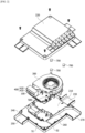
- FIG. 1 is a perspective view illustrating a cooling/warming device according to one embodiment of the present invention
- FIG. 2 is an exploded perspective view illustrating the cooling/warming device according to one embodiment of the present invention
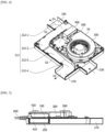
- FIG. 3 is a top view illustrating a fan, a thermoelectric device, and a controller which are disposed in a lower case of the cooling/warming device according to one embodiment of the present invention
- FIG. 4 is a perspective view of FIG. 3 .
- FIG, 5 is a side view of FIG. 3
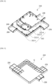
- FIG. 6 is a perspective view illustrating an interior of an upper case of the cooling/warming device according to one embodiment of the present invention
- FIG. 7 is a perspective view illustrating an exterior of the upper case of the cooling/warming device according to one embodiment of the present invention
- FIG. 8 is a perspective view illustrating an interior of the lower case of the cooling/warming device according to one embodiment of the present invention
- FIG. 9 is a perspective view illustrating an exterior of the lower case of the cooling/warming device according to one embodiment of the present invention
- FIG. 10 is a cross-sectional view illustrating a thermoelectric element included in the cooling/warming device according to one embodiment of the present invention
- FIG. 11 is a perspective view illustrating the thermoelectric element included in the cooling/warming device according to one embodiment of the present invention
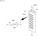
- FIGS. 13 to 15 are views for describing a heat transmission member included in the cooling/warming device according to one embodiment of the present invention.
- a cooling/warming device 1000 includes a case 200 having a lower case 210 and an upper case 220 connected to the lower case 210, a fan 300 accommodated in the case 200 and configured to circulate air introduced into the case 200, a thermoelectric device 400 accommodated in the case 200, disposed on a side surface of the fan 300, and configured to cool some air circulated by the fan 300 and to heat some air which is remaining, and a controller 500 connected to the thermoelectric device 400 and the fan 300 and configured to control operation of the thermoelectric device 400 and the fan 300.
- the fan 300, the thermoelectric device 400, and the controller 500 may be connected to a cable 600 and may receive external power through the cable 600.
- the fan 300, the thermoelectric device 400, and the controller 500 may also receive power from a pre-installed battery.
- the controller 500 may include a printed circuit board and an electronic component mounted on the printed circuit board.
- the controller 500 may also include a communication module and may control operation of the thermoelectric device 400 and the fan 300 using a signal received from the outside through the communication module.
- the communication module may use Bluetooth, short range wireless communication, Wi-Fi, or the like.
- the thermoelectric device 400 includes a first heat transmission member 410 disposed at a side of the lower case 210, a second heat transmission member 420 disposed at a side of the upper case 220, and a thermoelectric element 100 disposed between the first heat transmission member 410 and the second heat transmission member 420.
- the thermoelectric element 100 includes a lower substrate 110, lower electrodes 120, a P-type thermoelectric leg 130, an N-type thermoelectric leg 140, an upper electrode 150, and an upper substrate 160.
- the lower electrodes 120 are disposed between the lower substrate 110 and lower floor surfaces of the P-type thermoelectric leg 130 and the N-type thermoelectric leg 140, and the upper electrode 150 is disposed between the upper substrate 160 and upper floor surfaces of the P-type thermoelectric leg 130 and the N-type thermoelectric leg 140. Accordingly, a plurality of P-type thermoelectric legs 130 and a plurality of N-type thermoelectric legs 140 are electrically connected by lower electrodes 120 and upper electrodes 150.
- the pair of P-type thermoelectric leg 130 and N-type thermoelectric leg 140 which are disposed between the lower electrodes 120 and the upper electrode 150 and electrically connected to each other may form a unit cell.
- the substrate through which a current flows from the P-type thermoelectric leg 130 to the N-type thermoelectric leg 140 absorbs heat and thus serves as a cooling part, and the substrate through which a current flows from the N-type thermoelectric leg 140 to the P-type thermoelectric leg 130 is heated and thus serves as a heating part.
- the heat-absorbing surface may also be one surface of the substrate serving as the cooling part, and the heating surface may also be one surface of the substrate serving as the heating part.
- the P-type thermoelectric leg 130 and the N-type thermoelectric leg 140 may be bismuth-telluride (Bi-Te)-based thermoelectric legs mainly including bismuth (Bi) and tellurium (Te).
- the P-type thermoelectric leg 130 may be a thermoelectric leg including a Bi-Te-based main material containing at least one among antimony (Sb), nickel (Ni), aluminum (Al), copper (Cu), silver (Ag), lead (Pb), boron (B), gallium (Ga), tellurium (Te), bismuth (Bi), and indium (In) in the range of 99 to 99.999 wt% and a mixture containing Bi or Te in the range of 0.001 to 1 wt% based on a total weight of 100 wt%.
- a main material of the P-type thermoelectric leg 130 may be Bi-selenium (Se)-Te, and the P-type thermoelectric leg 130 may further include Bi or Te in the range of 0.001 to 1 wt% based on a total weight.
- the N-type thermoelectric leg 140 may be a thermoelectric leg including a Bi-Te-based main material containing at least one among Se, Ni, Cu, Ag, Pb, B, Ga, Te, Bi, and In in the range of 99 to 99.999 wt% and a mixture containing Bi or Te in the range of 0.001 to 1 wt% based on a total weight of 100 wt%.
- a main material of the N-type thermoelectric leg 140 may be Bi-Sb-Te, and the N-type thermoelectric leg 140 may further include Bi or Te in the range of 0.001 to 1 wt% based on a total weight.
- the P-type thermoelectric leg 130 and the N-type thermoelectric leg 140 may be formed in a bulk type or a stacked type.
- the bulk type P-type thermoelectric leg 130 or the bulk type N-type thermoelectric leg 140 may be formed by performing a thermal process on a thermoelectric material to manufacture an ingot, grinding and straining the ingot to obtain a powder for a thermoelectric leg, sintering the powder, and cutting a sintered body.
- the stacked type P-type thermoelectric leg 130 or the stacked type N-type thermoelectric leg 140 may be formed by coating a sheet-shaped base with a paste including a thermoelectric material to form unit members, stacking the unit members, and cutting the stacked unit members.
- the pair of P-type thermoelectric leg 130 and N-type thermoelectric leg 140 may have the same shape and volume or may have different shapes and volumes.
- a height or cross sectional area of the N-type thermoelectric leg 140 may be different from that of the P-type thermoelectric leg 130.
- thermoelectric element The performance of the thermoelectric element according to one embodiment of the present invention may be expressed as a Seebeck index.
- ⁇ is the Seebeck coefficient [V/K]
- ⁇ is electric conductivity [S/m]
- ⁇ 2 ⁇ is a power factor [W/mK 2 ].
- T is temperature
- k is thermal conductivity [W/mK]. k may be expressed as a ⁇ c p ⁇ , wherein a is thermal diffusivity [cm 2 /S], c p is specific heat [J/gK], and ⁇ is density [g/cm 3 ].
- a Z value [V/K] is measured using a Z meter, and then, the Seebeck index (ZT) may be calculated using the measured Z value.
- each of the lower electrodes 120 disposed between the lower substrate 110 and the P-type thermoelectric leg 130 and between the lower substrate 110 and the N-type thermoelectric leg 140, and the upper electrode 150 disposed between the upper substrate 160 and the P-type thermoelectric leg 130 and between the upper substrate 160 and the N-type thermoelectric leg 140 may include at least one among Cu, Ag, and Ni and may have a thickness in the range of 0.01 mm to 0.3 mm. In a case in which a thickness of the lower electrode 120 or the upper electrode 150 is less than 0.01 mm, an electrode function thereof is degraded so that electric conductivity performance thereof may be lowered, and in a case in which the thickness thereof is greater than 0.3 mm, resistance thereof increases so that conduction efficiency thereof may be lowered.
- the lower substrate 110 and the upper substrate 160 which face each other may be insulating substrates or metal substrates.
- the insulating substrate may be an alumina substrate or flexible polymer resin substrate.
- the flexible polymer resin substrate may include any insulating resin material such as high permeability plastics including polyimide (PI), polystyrene (PS), poly methyl methacrylate (PMMA), a cyclic olefin copolymer (COC), polyethylene terephthalate (PET), or a resin.
- the metal substrate may include Cu, a Cu alloy, or a Cu-Al alloy, and a thickness thereof may be in the range of 0.1 mm to 0.5 mm.
- the thickness of the metal substrate is less than 0.1 mm or greater than 0.5 mm, since a heat dissipation property or thermal conductivity thereof may become excessively high, the reliability of the thermoelectric element may be lowered.
- dielectric layers 170 may be further formed between the lower substrate 110 and the lower electrodes 120 and between the upper substrate 160 and the upper electrode 150.
- the dielectric layer 170 may include a material having a thermal conductivity in the range of 5 to 10 W/K and may have a thickness in the range of 0.01 mm to 0.15 mm.
- the thickness of the dielectric layer 170 is less than 0.01 mm, insulating efficiency or a withstanding voltage property may be lowered, and in a case in which the thickness thereof is greater than 0.15 mm, thermal conductivity is lowered so that heat dissipation efficiency may be lowered.
- sizes of the lower substrate 110 and the upper substrate 160 may also be different.
- a volume, a thickness, or an area of one of the lower substrate 110 and the upper substrate 160 may be greater than that of the other. Accordingly, the heat absorption or dissipation performance of the thermoelectric element can be enhanced.
- a heat dissipation pattern for example, an irregular pattern
- the irregular pattern is formed on a surface in contact with the P-type thermoelectric leg 130 or N-type thermoelectric leg 140, a bonding property between the thermoelectric leg and the substrate can also be improved.
- the P-type thermoelectric leg 130 or N-type thermoelectric leg 140 may have a cylindrical form, a polygonal column form, an elliptical column form, or the like.
- the P-type thermoelectric leg 130 or the N-type thermoelectric leg 140 may also have a stacked type structure.
- the P-type thermoelectric leg or the N-type thermoelectric leg may be formed through a method in which a plurality of structures applied with a semiconductor material are stacked on a base member having a sheet form and are cut. Accordingly, material loss can be prevented, and an electrical conductivity property can be improved.
- the P-type thermoelectric leg 130 or the N-type thermoelectric leg 140 may be manufactured through a zone melting method or a powder sintering method.
- zone melting method after an ingot is manufactured using a thermoelectric material, the ingot is slowly heated and refined such that particles are rearranged in a single direction and is slowly cooled to obtain a thermoelectric leg.
- powder sintering method after an ingot is manufactured using a thermoelectric material, the ingot is grinded and strained to obtain a powder for a thermoelectric leg, and a sintering process is performed on the powder to obtain a thermoelectric leg.
- the lower substrate 110 may be disposed on a side of the first heat transmission member 410, and the upper substrate 160 may be disposed on a side of the second heat transmission member 420.
- the lower substrate 110 may be directly or indirectly connected to the first heat transmission member 410, and the upper substrate 160 may be directly or indirectly connected to the second heat transmission member 420.
- cooled air may be discharged through the first heat transmission member 410, and heated air may be discharged through the second heat transmission member 420.
- heated air may be discharged through the first heat transmission member 410, and cooled air may be discharged through the second heat transmission member 420.
- first heat transmission member 410 and the second heat transmission member 420 may be formed to have various forms to increase contact areas with air.
- the first heat transmission member 410 and the second heat transmission member 420 may have structures illustrated in FIGS. 13 to 15 .
- a heat transmission member 2200 according to the embodiment of the present invention may include at least one flow path pattern 2200A forming an air flow path C1 using a base member including a first flat surface 2210 and a second flat surface 2220 and having a flat plate form.
- the flow path pattern 2200A may have a structure in which the base member is folded to form a curvature pattern having predetermined pitches P1 and P2 and a predetermined height T1, that is, a folded structure.
- air comes into surface-contact with the first flat surface 2210 and the second flat surface 2220 of the heat transmission member 2200, and an area with which the air comes into contact may be maximized due to the flow path pattern 200A.
- air may move while uniformly coming into contact with the first flat surface 2210 and the second flat surface 2220 and move in a flow path direction C2. Accordingly, since a contact surface is large when compared to a base member having a simple flat plate form, a heat-absorbing or heating effect is improved.
- a protruding resistive pattern 2230 may also be formed on the base member.
- the resistive pattern 2230 may be formed as a protruding structure inclined at a predetermined inclination ⁇ in a direction in which air is introduced. Accordingly, since friction between the resistive pattern 2230 and the air may be maximized, a contact surface can be increased or contact efficiency can be improved.
- a groove 2240 may also be formed in a surface of a front portion of the resistive pattern 2230 of the base member. Since some air coming into contact with the resistive pattern 2230 passes through the groove 2240 and moves along a front surface and a rear surface of the base member, a contact area can be further increased or contact efficiency can be further improved.
- the resistive pattern 2230 is illustrated to be formed on the first flat surface 2210 but is not limited thereto and may also be formed on the second flat surface 2220.
- the flow path pattern may have variously modified examples.
- a pattern having a curvature may be repeated with a predetermined pitch P1 as illustrated in FIG. 15A
- a pattern having a cutting edge portion may be repeated as illustrated in FIG. 15B
- unit patterns may also have polygonal shapes as illustrated in FIGS. 15C and 15D .
- a resistive pattern may also be formed on each of surfaces B1 and B2 of the patterns.
- the flow path pattern has a predetermined cycle and a height but is not limited thereto, and the cycle and the height T1 of the flow path pattern may be non-uniformly changed.
- the cooling/warming device 1000 includes an inlet 230 through which air is introduced into the case 200, an air blow pipe 240 through which air passing through the first heat transmission member 410 flows, an air blow port 250 through which air passing through the air blow pipe 240 is discharged, a discharge pipe 260 through which air passing through the second heat transmission member 420 flows, and a discharge outlet 270 through which air flowing through the discharge pipe 260 is discharged.
- the inlet 230, the air blow pipe 240, the air blow port 250, the discharge pipe 260, and the discharge outlet 270 may be formed on the lower case 210 and formed by coupling the lower case 210 and the upper case 220.
- the lower case 210 and the upper case 220 are illustrated to be coupled by bolts but are not limited thereto, and the lower case 210 and the upper case 220 may be coupled through various methods.
- thermoelectric device 400 air introduced into the case 200 from outside of the cooling/warming device 1000 through the inlet 230 may be circulated by the fan 300 and moved toward the thermoelectric device 400.
- the first heat transmission member 410 and the second heat transmission member 420 included in the thermoelectric device 400 may be disposed in a direction of an air flow path formed from a side of the fan 300 toward a side of the air blow port 250.
- the cooling/warming device 1000 is used as a cooling device, the lower substrate 110 of the thermoelectric element 100 becomes a heat-absorbing portion, thus the first heat transmission member 410 is cooled, the upper substrate 160 becomes a heating portion, and thus the second heat transmission member 420 is heated.
- thermoelectric device 400 may pass through the first heat transmission member 410 and be cooled, and some air which is remaining may pass through the second heat transmission member 420 and may be heated.
- the cooled air may be blown to the air blow port 250 through the air blow pipe 240, and the heated air may be discharged to the discharge outlet 270 through the discharge pipe 260.
- the cooling/warming device 1000 is used as a warming device, the lower substrate 110 of the thermoelectric element 100 becomes a heating portion, thus the first heat transmission member 410 is heated, the upper substrate 160 becomes a heat-absorbing portion, and thus the second heat transmission member 420 is cooled.
- thermoelectric device 400 may pass through the first heat transmission member 410 and be heated, and some air which is remaining may pass through the second heat transmission member 420 and may be cooled.
- the heated air may be blown to the air blow port 250 through the air blow pipe 240, and the cooled air may be discharged to the discharge outlet 270 through the discharge pipe 260.
- air which is circulated by the fan 300 and passes through the first heat transmission member 410, may flow through the air blow pipe 240 and may be blown from the air blow port 250, and may be used for cooling or heating.
- air passing through the second heat transmission member 420 may flow through the discharge pipe 260 and may be discharged from the discharge outlet 270 to the outside.
- the discharge pipe 260 may be formed to include an inclined surface at a predetermined point between the second heat transmission member 420 and the discharge outlet 270. Accordingly, air discharged from the second heat transmission member 420 may be effectively discharged to the discharge outlet 270 without being hindered in a flow path.
- a direction D1 in which air is discharged through the air blow port 250 may be different from a direction D2 in which air is discharged through the discharge outlet 270. Accordingly, air, which is cooled or heated and discharged from the air blow port 250 to achieve performance of the cooling/warming device 1000, is not mixed with air, which is discharged from the discharge pipe 260 to be discharged after being used to cool or heat the air discharged from the air blow port 250, and thus cooling or heating performance can be improved.
- the air blow port 250 may be disposed in a first side surface S1 of the lower case 210, and the discharge outlet 270 may be disposed in a second side surface S2, which is different from the first side surface S 1, of the lower case 210.
- the first side surface S1 may be a surface disposed in a direction in which air is moved after the air is circulated by the fan 300 and cooled and heated by the thermoelectric device 400 and passes through the first heat transmission member 410 and the second heat transmission member 420.
- the second side surface S2 may be a surface disposed between the first side surface S1 and a third side surface S3 opposite to the first side surface S1.
- the discharge outlet 270 may be formed in a region of the second side surface S2 which is closer to the third side surface S3 than the first side surface S1.
- the discharge outlet 270 may be disposed in the region A2. Then, since a distance between the discharge outlet 270 and the air blow port 250 increases, air discharged from the discharge outlet 270 may not be mixed with air blown from the air blow port 250.
- the inlet 230 may be disposed in a side surface different from the first side surface S1, for example, in the second side surface S2, the third side surface S3 opposite to the first side surface S1, or a fourth side surface S4 opposite to the second side surface S2, and may preferably be disposed in the third side surface S3 or the fourth side surface S4.
- cooling/warming performance of the cooling/warming device can be improved.
- a separate air moving path may be further selectively connected to one or more of the inlet 230, the air blow port 250, and the discharge outlet 270 to further control an air introduction, blowing or discharging direction.
- directions in which air is initially introduced, finally blown or finally discharged through the air moving path selectively connected to the inlet 230, the air blow port 250, and the discharge outlet 270 may be different from each other.
- the discharge outlet 270 in addition to the air blow pipe 240, air blow port 250, and the discharge pipe 260 may be formed in the lower case 210.
- three surfaces of the discharge outlet 270 are formed due to the lower case 210, and one surface thereof may be covered by the upper case 220. Accordingly, since both of the air blow port 250 and the discharge outlet 270 of the cooling/warming device 1000 are formed in the lower case 210, the cooling/warming device 1000 can be manufactured to have a slim design.
- the discharge pipe 260 may be formed to be inclined from an outlet through which air passing through the second heat transmission member 420 is discharged to the discharge outlet 270 while being bent at a predetermined curvature.
- the discharge pipe 260 may include at least one inclined surface formed at a predetermined position. Accordingly, air passing through the second heat transmission member 420 may be discharged to the discharge outlet 270 through the discharge pipe 260 without being hindered in a flow path.
- the discharge pipe 260 may have a structure bent two or three times at a predetermined curvature.
- the discharge pipe 260 is formed due to the lower case 210 and the upper case 220 being coupled, and air passing through the air blow pipe 240 may not be mixed with air passing through the discharge pipe 260.
- the discharge pipe 260 may be formed due to a discharge pipe bottom surface 212 included in the lower case 210 being coupled to a discharge pipe cover 222 formed in the upper case 220.
- the discharge pipe bottom surface 212 may include a dividing region 212-1, a bent region 212-2, an inclined region 212-3, and a discharge region 212-4, and the dividing region 212-1 may be a region disposed between an outlet through which air passing through the first heat transmission member 410 is discharged and the outlet through which air passing through the second heat transmission member 420 is discharged to be parallel to the lower substrate 110 and the upper substrate 160 of the thermoelectric device 400 and from which the air is divided.
- the air blow pipe 240 may be formed between the bottom surface of the lower case 210 and the dividing region 212-1.
- the bent region 212-2 may be a region which extends from the dividing region 212-1, is bent at a predetermined curvature, and changes a path of air which passes through the second heat transmission member 420 and flows in the dividing region 212-1.
- the inclined region 212-3 may be a region through which air passing through the bent region 212-2 is moved to the discharge region 212-4, and heights of bottom surfaces of regions are different such that an initial height of the air passing through the bent region 212-2 is different from a final height of the air transmitted to the discharge region 212-4, and the final height of the air transmitted to the discharge region 212-4 may be lower than the initial height of the air passing through the bent region 212-2.
- a height of the inclined region 212-3 at a starting point thereof may be higher than a height of the inclined region 212-3 at an ending point thereof.
- the height of the inclined region 212-3 at the starting point may be linearly, nonlinearly, cycloidally, or stepwise decreased to the height of the inclined region 212-3 at the ending point. That is, a form having a linear type slope, a slope with a curvature, a step in a stair type, or a combination of a slope and a step may be disposed between the bottom surfaces of the regions.
- a position of the inclined region 212-3 is not limited thereto, and the inclined region 212-3 may be disposed in the dividing region 212-1, the bent region 212-2, or the discharge region 212-4 or disposed between the dividing region 212-1 and the bent region 212-2 and may be preferably formed in a region spaced far apart from the air blow pipe 240, that is, a region adjacent to the discharge outlet 270, so as to minimize a thermal effect on air passing through the air blow pipe 240.
- the inclined region 212-3 may be disposed in a direction opposite to the direction D1 in which air passing through the first heat transmission member 410 is discharged to the air blow port 250 through the air blow pipe 240.
- air passing through the first heat transmission member 410 and air passing through the second heat transmission member 420 may be divided by the dividing region 212-1, the air passing through the first heat transmission member 410 may be discharged through the air blow port 250, and the air passing through the second heat transmission member 420 may be discharged through the discharge outlet 270.
- the cooling/warming device 1000 may further include two or more buffer members 700 disposed on an upper surface of the fan 300, and the buffer members 700 may be in contact with the upper case 220.
- the buffer member 700 may be a member having elasticity and may be adhered or connected to the upper surface of the fan 300. Accordingly, a problem of noise generated due to contact between the fan 300 and the upper case 220 when the fan 300 vibrates can be prevented.
- two or more protrusions 224 may be formed on an inner surface of the upper case 220, and the buffer member 700 may be in contact with the protrusion 224.
- At least one groove G may be disposed in at least one outer surface of the lower case 210 and the upper case 220.
- the groove G may be disposed in a surface disposed at the side surface of the fan 300 among a plurality of outer surfaces of the upper case 220.
- the surface disposed on the side surface of the fan 300 may be disposed to have a predetermined inclination with respect to a surface disposed on the upper surface of the fan 300, and a plurality of grooves identical to the groove G may have a predetermined pattern.
- a depth H of the groove G may range from 0.5 to 1.5 times a width W of the groove G.
- the fan 300 when the surface disposed on the side surface of the fan 300 has the predetermined inclination with respect to the surface disposed on the upper surface of the fan 300, the fan 300 can be stably accommodated in the upper case 220, and a flow path of the discharge pipe 260 can be easily designed.
- the groove G has the predetermined pattern and the depth H of the groove G ranges from 0.5 to 1.5 times the width of the groove G, a weight of the case 200 can be reduced, a material cost can be reduced, and a mechanical strength of the case 200 can also be suitably maintained.
- the groove G may also be formed in a region corresponding to the inclined region 212-3 among the plurality of outer surfaces of the lower case 210.
- the plurality of grooves G formed in the lower case 210 may have a predetermined inclination and a predetermined pattern, and inclinations of some of the plurality of grooves may be different from inclinations of the remaining grooves.
- the depth H of the groove G may range from 0.5 to 1.5 times the width W of the groove G, and depths of some of the plurality of grooves may be different from depths of the remaining grooves.
- a weight of the case 200 can be reduced, a material cost can be reduced, a mechanical strength of the case 200 can also be suitably maintained, and the case 200 can be firmly fixed because sliding can be prevented when the case 200 is installed in an application product in which vibration occurs.
Landscapes
- Engineering & Computer Science (AREA)
- Physics & Mathematics (AREA)
- Mechanical Engineering (AREA)
- Thermal Sciences (AREA)
- General Engineering & Computer Science (AREA)
- Cooling Or The Like Of Electrical Apparatus (AREA)
Claims (14)
- Kühl-/Erwärmungsvorrichtung (1000), umfassend:ein Gehäuse (200) mit einem unteren Gehäuse (210) und einem oberen Gehäuse (220), das mit dem unteren Gehäuse (210) verbunden ist;einen Ventilator (300), der in dem Gehäuse (200) untergebracht ist und in das Gehäuse (200) eingeführte Luft umwälzt;eine thermoelektrische Vorrichtung (400), die in dem Gehäuse untergebracht ist, an einer Seitenfläche des Ventilators (300) angeordnet ist, einen Teil der von dem Ventilator (300) erzeugten Luft kühlt und die restliche Luft erwärmt; undeine Steuerung (500), die mit der thermoelektrischen Vorrichtung (400) und dem Ventilator (300) verbunden ist und den Betrieb der thermoelektrischen Vorrichtung (400) und des Ventilators (300) steuert,wobei die thermoelektrische Vorrichtung (400) ein erstes Wärmeübertragungselement (410), das an einer Seite des unteren Gehäuses (210) angeordnet ist, ein zweites Wärmeübertragungselement (420), das an einer Seite des oberen Gehäuses (220) angeordnet ist, und ein thermoelektrisches Element (100) umfasst, das zwischen dem ersten Wärmeübertragungselement (410) und dem zweiten Wärmeübertragungselement (420) angeordnet ist,wobei das thermoelektrische Element (100) ein erstes Substrat, das an einer Seite des ersten Wärmeübertragungselements (410) angeordnet ist, ein zweites Substrat, das an einer Seite des zweiten Wärmeübertragungselements (420) angeordnet ist, und eine Vielzahl von thermoelektrischen Beinen (130) vom P-Typ und eine Vielzahl von thermoelektrischen Beinen (140) vom N-Typ, die abwechselnd zwischen dem ersten Substrat und dem zweiten Substrat angeordnet sind, umfasst,das Gehäuse (200) einen Einlass (230) einschließt, durch den Luft in das Gehäuse (200) eingeleitet wird, ein Luftblasrohr (240), durch das Luft, die durch das erste Wärmeübertragungselement (410) strömt, hindurchströmt, eine Luftblasöffnung (250), aus der die durch das Luftblasrohr (240) strömende Luft ausgestoßen wird, ein Ausblasrohr (260), durch das Luft strömt, die durch das zweite Wärmeübertragungselement (420) strömt, und einen Ausblasauslass (270), aus dem die durch das Ausblasrohr (260) strömende Luft ausgestoßen wird, und eine Bodenfläche des Ausblasrohrs (260) umfasst geneigte Bereiche mit unterschiedlichen Höhen an einem vorbestimmten Punkt,wobei die Bodenfläche des Ausblasrohrs (260) ferner einen Trennbereich, der die durch das erste Wärmeübertragungselement (410) strömende Luft von der durch das zweite Wärmeübertragungselement (420) strömenden Luft trennt, einen gebogenen Bereich (212-2), der den Weg der durch das zweite Wärmeübertragungselement (420) strömenden Luft ändert, und einen Auslassbereich (212-4), von dem aus die durch das zweite Wärmeübertragungselement (420) strömende Luft zum Auslass (270) geleitet wird, aufweist, undder geneigte Bereich zwischen dem gebogenen Bereich (212-2) und dem Auslassbereich (212-4) angeordnet ist.
- Kühl-/Wärmevorrichtung nach Anspruch 1, wobei eine Höhe einer Bodenfläche des gebogenen Bereichs (212-2) höher ist als eine Höhe einer Bodenfläche des Auslassbereichs (212-4).
- Kühl-/Erwärmungsvorrichtung nach Anspruch 1 oder 2,
wobei der geneigte Bereich eine beliebige Form zwischen einer Steigung in einer linearen Art, einer Steigung mit einer Krümmung und einer Stufe in einem Treppentyp aufweist. - Die Kühl-/Wärmevorrichtung nach einem der vorstehenden Ansprüche, die so konfiguriert ist, dass eine Richtung, in der Luft durch die Luftblasöffnung (250) geblasen wird, sich von einer Richtung unterscheidet, in der Luft durch den Ausblasauslass (270) ausgestoßen wird.
- Kühl-/Wärmevorrichtung nach Anspruch 4, wobei:die Luftblasöffnung (250) an einer ersten Seitenfläche des unteren Gehäuses (210) angeordnet ist; undder Einlass (230) auf einer dritten Seitenfläche gegenüber der ersten Seitenfläche angeordnet ist.
- Kühl-/Wärmevorrichtung nach Anspruch 5, wobei der Ausblasauslass (270) an einer zweiten Seitenfläche zwischen der ersten Seitenfläche und der dritten Seitenfläche angeordnet ist.
- Kühl-/Erwärmungsvorrichtung nach einem der vorstehenden Ansprüche,
wobei der gebogene Bereich (212-2) des Ausblasrohrs (260) von einem Auslass, aus dem die durch das zweite Wärmeübertragungselement (420) hindurchtretende Luft abgeleitet wird, zum Ausblasauslass (270) gebogen ist und dabei eine vorgegebene Krümmung aufweist. - Kühl-/Erwärmungsvorrichtung nach einem der vorstehenden Ansprüche, wobei:das Ausblasrohr (260) durch einen Zwischenraum zwischen dem unteren Gehäuse (210) und dem oberen Gehäuse (220) gebildet ist; undLuft, die durch das Luftblasrohr (240) strömt, und Luft, die durch das Ausblasrohr (260) strömt, nicht vermischt werden.
- Kühl-/Erwärmungsvorrichtung nach einem der vorstehenden Ansprüche, wobei:der Trennbereich des Ausblasrohrs (260) zwischen einem Auslass, durch den die durch das erste Wärmeübertragungselement (410) strömende Luft ausgestoßen wird, und einem Auslass, durch den die durch das zweite Wärmeübertragungselement (420) strömende Luft ausgestoßen wird, so angeordnet ist, dass er parallel zu dem ersten Substrat und dem zweiten Substrat der thermoelektrischen Vorrichtung (400) liegt; undder gebogene Bereich (212-2) zwischen dem Trennbereich und dem geneigten Bereich angeordnet ist.
- Kühl-/Wärmevorrichtung nach Anspruch 9, wobei das Luftblasrohr (240) zwischen einer Bodenfläche des unteren Gehäuses (210) und dem Trennbereich angeordnet ist.
- Kühl-/Wärmevorrichtung nach einem der vorstehenden Ansprüche, die ferner zwei oder mehr Pufferelemente (700) umfasst, die auf einer oberen Fläche des Ventilators (300) angeordnet sind,
wobei das Pufferelement (700) in Kontakt mit dem oberen Gehäuse (220) steht. - Kühl-/Wärmevorrichtung nach Anspruch 11, wobei:zwei oder mehr Vorsprünge (224) an einer Innenfläche des oberen Gehäuses (220) ausgebildet sind; unddas Pufferelement (700) in Kontakt mit dem Vorsprung (224) ist.
- Kühl-/Erwärmungsvorrichtung nach einem der vorstehenden Ansprüche,
wobei in mindestens einer Außenfläche des oberen Gehäuses (220) und des unteren Gehäuses (210) eine Vielzahl von Rillen ausgebildet ist. - Kühl-/Wärmevorrichtung nach einem der vorstehenden Ansprüche, die so konfiguriert ist, dass:wenn gekühlte Luft durch die Luftblasöffnung (250) ausgestoßen wird, erwärmte Luft durch den Ausblasauslass (270) ausgestoßen wird; undwenn erwärmte Luft durch die Luftblasöffnung (250) ausgestoßen wird, gekühlte Luft durch den Ausblasauslass (270) ausgestoßen wird.
Applications Claiming Priority (2)
| Application Number | Priority Date | Filing Date | Title |
|---|---|---|---|
| KR1020170096479A KR102385208B1 (ko) | 2017-07-28 | 2017-07-28 | 냉온장치 |
| PCT/KR2018/008562 WO2019022570A1 (ko) | 2017-07-28 | 2018-07-27 | 냉온장치 |
Publications (3)
| Publication Number | Publication Date |
|---|---|
| EP3660416A1 EP3660416A1 (de) | 2020-06-03 |
| EP3660416A4 EP3660416A4 (de) | 2021-04-14 |
| EP3660416B1 true EP3660416B1 (de) | 2023-07-26 |
Family
ID=65039681
Family Applications (1)
| Application Number | Title | Priority Date | Filing Date |
|---|---|---|---|
| EP18837847.5A Active EP3660416B1 (de) | 2017-07-28 | 2018-07-27 | Kühl-/wärmvorrichtung |
Country Status (6)
| Country | Link |
|---|---|
| US (1) | US11374159B2 (de) |
| EP (1) | EP3660416B1 (de) |
| JP (1) | JP7198449B2 (de) |
| KR (1) | KR102385208B1 (de) |
| CN (1) | CN110959095B (de) |
| WO (1) | WO2019022570A1 (de) |
Families Citing this family (3)
| Publication number | Priority date | Publication date | Assignee | Title |
|---|---|---|---|---|
| KR102029989B1 (ko) * | 2019-04-04 | 2019-11-18 | 주식회사 티엠아이 | 냉온풍 키트 |
| WO2022173547A1 (en) * | 2021-01-26 | 2022-08-18 | Ergomotion, Inc. | Under base integral climate control for an articulating bed |
| WO2025146925A1 (ko) * | 2024-01-05 | 2025-07-10 | 삼성전자주식회사 | 열전 냉각 장치 및 이를 포함하는 냉장고 |
Family Cites Families (23)
| Publication number | Priority date | Publication date | Assignee | Title |
|---|---|---|---|---|
| JPH06163997A (ja) * | 1992-11-20 | 1994-06-10 | Matsushita Electric Ind Co Ltd | 熱電効果を用いた除湿装置およびその制御方法 |
| JP3942248B2 (ja) * | 1997-02-24 | 2007-07-11 | 富士通株式会社 | ヒートシンクおよびそれを搭載した情報処理装置 |
| US6118655A (en) | 1997-12-08 | 2000-09-12 | Compaq Computer Corporation | Cooling fan with heat pipe-defined fan housing portion |
| JP3055679B2 (ja) * | 1998-10-12 | 2000-06-26 | モリックス株式会社 | 熱電モジュールジャケット、熱電加熱冷却装置、熱電モジュールジャケットの製造方法、及び熱電加熱冷却装置の製造方法 |
| JP4173694B2 (ja) | 2002-06-18 | 2008-10-29 | 株式会社ケーヒン | 車両用隔壁 |
| JP2005140430A (ja) | 2003-11-07 | 2005-06-02 | Sharp Corp | 空気調和機 |
| KR20060104294A (ko) * | 2005-03-30 | 2006-10-09 | 엘지전자 주식회사 | 팬모터 구조체 |
| JP2007126047A (ja) | 2005-11-04 | 2007-05-24 | Denso Corp | 車両用シート空調装置 |
| JP2007240046A (ja) * | 2006-03-07 | 2007-09-20 | Denso Corp | 空調装置 |
| KR100778484B1 (ko) * | 2006-04-04 | 2007-11-21 | 엘지전자 주식회사 | 카세트형 공기조화기 |
| JP5103993B2 (ja) * | 2007-04-06 | 2012-12-19 | 三菱樹脂株式会社 | 車両用除加湿装置 |
| US20090082927A1 (en) * | 2007-09-25 | 2009-03-26 | W.E.T. Automotive Systems Ag | Integrated seat conditioning and multi-component control module |
| EP3121060A1 (de) | 2008-02-01 | 2017-01-25 | Gentherm Incorporated | Kondensations- und feuchtigkeitssensoren für thermoelektrische vorrichtungen |
| JP2009274587A (ja) | 2008-05-14 | 2009-11-26 | Denso Corp | 車両用除加湿装置 |
| KR20110030192A (ko) | 2009-09-17 | 2011-03-23 | 현대자동차주식회사 | 열전소자를 이용한 열교환기 |
| KR101241160B1 (ko) * | 2010-12-09 | 2013-03-13 | 현대자동차주식회사 | 차량의 냉난방 통풍시트 모듈 |
| TWI517782B (zh) * | 2011-11-11 | 2016-01-11 | 華碩電腦股份有限公司 | 散熱模組 |
| CN102848952A (zh) * | 2012-09-21 | 2013-01-02 | 深圳先进技术研究院 | 调温装置 |
| KR102281066B1 (ko) | 2015-03-27 | 2021-07-23 | 엘지이노텍 주식회사 | 열전소자, 열전모듈 및 이를 포함하는 열전환장치 |
| KR102190386B1 (ko) * | 2015-06-26 | 2020-12-11 | 이영민 | 드레스룸 환경조성장치 |
| KR101727413B1 (ko) * | 2015-12-08 | 2017-04-14 | 엘지전자 주식회사 | 공기 조화기의 에어가이드 |
| JP2017171131A (ja) * | 2016-03-24 | 2017-09-28 | パナソニックIpマネジメント株式会社 | 車載空調装置 |
| KR102060356B1 (ko) * | 2018-04-12 | 2019-12-30 | 엘지전자 주식회사 | 조리기기 |
-
2017
- 2017-07-28 KR KR1020170096479A patent/KR102385208B1/ko active Active
-
2018
- 2018-07-27 CN CN201880049482.6A patent/CN110959095B/zh active Active
- 2018-07-27 JP JP2020502158A patent/JP7198449B2/ja active Active
- 2018-07-27 EP EP18837847.5A patent/EP3660416B1/de active Active
- 2018-07-27 US US16/630,955 patent/US11374159B2/en active Active
- 2018-07-27 WO PCT/KR2018/008562 patent/WO2019022570A1/ko not_active Ceased
Also Published As
| Publication number | Publication date |
|---|---|
| KR102385208B1 (ko) | 2022-04-11 |
| JP2020528992A (ja) | 2020-10-01 |
| CN110959095A (zh) | 2020-04-03 |
| US20200227611A1 (en) | 2020-07-16 |
| EP3660416A1 (de) | 2020-06-03 |
| EP3660416A4 (de) | 2021-04-14 |
| US11374159B2 (en) | 2022-06-28 |
| CN110959095B (zh) | 2021-11-30 |
| KR20190012854A (ko) | 2019-02-11 |
| JP7198449B2 (ja) | 2023-01-04 |
| WO2019022570A1 (ko) | 2019-01-31 |
Similar Documents
| Publication | Publication Date | Title |
|---|---|---|
| EP3723144B1 (de) | Wärmeumwandlungsvorrichtung | |
| EP3961732B1 (de) | Wärmeumwandlungsvorrichtung | |
| US11342490B2 (en) | Thermoelectric leg and thermoelectric element comprising same | |
| KR102773836B1 (ko) | 열전 소자 | |
| EP3660416A1 (de) | Kühl-/wärmvorrichtung | |
| EP3637485A1 (de) | Wärmeumwandlungsvorrichtung | |
| KR102271221B1 (ko) | 열전 소자 | |
| JP7293116B2 (ja) | 熱電焼結体および熱電素子 | |
| US20190126804A1 (en) | Cup holder | |
| KR102316222B1 (ko) | 열변환장치 | |
| KR20190038103A (ko) | 열전소자 | |
| KR102509339B1 (ko) | 열전 소자 | |
| EP3637019B1 (de) | Wärmeumwandlungsvorrichtung | |
| KR102310806B1 (ko) | 열전소자 | |
| KR20190088256A (ko) | 열전 소자 | |
| KR102358897B1 (ko) | 열전 소자 | |
| KR20230065207A (ko) | 열전소자 | |
| KR102570026B1 (ko) | 냉온풍기 및 이의 동작 방법 | |
| KR20200105190A (ko) | 냉온장치 | |
| KR20180088015A (ko) | 열전 소자 | |
| KR20200114779A (ko) | 열전 레그 및 이를 포함하는 열전 소자 | |
| KR102249020B1 (ko) | 열변환장치 | |
| KR102221688B1 (ko) | 열변환장치 | |
| KR20180086937A (ko) | 열전소자 어셈블리 | |
| KR20180089804A (ko) | 열전 소자 |
Legal Events
| Date | Code | Title | Description |
|---|---|---|---|
| STAA | Information on the status of an ep patent application or granted ep patent |
Free format text: STATUS: THE INTERNATIONAL PUBLICATION HAS BEEN MADE |
|
| PUAI | Public reference made under article 153(3) epc to a published international application that has entered the european phase |
Free format text: ORIGINAL CODE: 0009012 |
|
| STAA | Information on the status of an ep patent application or granted ep patent |
Free format text: STATUS: REQUEST FOR EXAMINATION WAS MADE |
|
| 17P | Request for examination filed |
Effective date: 20200122 |
|
| AK | Designated contracting states |
Kind code of ref document: A1 Designated state(s): AL AT BE BG CH CY CZ DE DK EE ES FI FR GB GR HR HU IE IS IT LI LT LU LV MC MK MT NL NO PL PT RO RS SE SI SK SM TR |
|
| AX | Request for extension of the european patent |
Extension state: BA ME |
|
| DAV | Request for validation of the european patent (deleted) | ||
| DAX | Request for extension of the european patent (deleted) | ||
| A4 | Supplementary search report drawn up and despatched |
Effective date: 20210316 |
|
| RIC1 | Information provided on ipc code assigned before grant |
Ipc: F25B 21/02 20060101AFI20210310BHEP Ipc: H01L 35/32 20060101ALI20210310BHEP Ipc: F25B 21/04 20060101ALI20210310BHEP |
|
| GRAP | Despatch of communication of intention to grant a patent |
Free format text: ORIGINAL CODE: EPIDOSNIGR1 |
|
| STAA | Information on the status of an ep patent application or granted ep patent |
Free format text: STATUS: GRANT OF PATENT IS INTENDED |
|
| INTG | Intention to grant announced |
Effective date: 20230206 |
|
| RIC1 | Information provided on ipc code assigned before grant |
Ipc: F25B 21/04 20060101ALI20230127BHEP Ipc: H10N 10/17 20230101ALI20230127BHEP Ipc: F25B 21/02 20060101AFI20230127BHEP |
|
| GRAS | Grant fee paid |
Free format text: ORIGINAL CODE: EPIDOSNIGR3 |
|
| GRAA | (expected) grant |
Free format text: ORIGINAL CODE: 0009210 |
|
| STAA | Information on the status of an ep patent application or granted ep patent |
Free format text: STATUS: THE PATENT HAS BEEN GRANTED |
|
| AK | Designated contracting states |
Kind code of ref document: B1 Designated state(s): AL AT BE BG CH CY CZ DE DK EE ES FI FR GB GR HR HU IE IS IT LI LT LU LV MC MK MT NL NO PL PT RO RS SE SI SK SM TR |
|
| REG | Reference to a national code |
Ref country code: CH Ref legal event code: EP |
|
| REG | Reference to a national code |
Ref country code: IE Ref legal event code: FG4D |
|
| REG | Reference to a national code |
Ref country code: DE Ref legal event code: R096 Ref document number: 602018054205 Country of ref document: DE |
|
| REG | Reference to a national code |
Ref country code: LT Ref legal event code: MG9D |
|
| REG | Reference to a national code |
Ref country code: NL Ref legal event code: MP Effective date: 20230726 |
|
| REG | Reference to a national code |
Ref country code: AT Ref legal event code: MK05 Ref document number: 1592337 Country of ref document: AT Kind code of ref document: T Effective date: 20230726 |
|
| PG25 | Lapsed in a contracting state [announced via postgrant information from national office to epo] |
Ref country code: NL Free format text: LAPSE BECAUSE OF FAILURE TO SUBMIT A TRANSLATION OF THE DESCRIPTION OR TO PAY THE FEE WITHIN THE PRESCRIBED TIME-LIMIT Effective date: 20230726 |
|
| PG25 | Lapsed in a contracting state [announced via postgrant information from national office to epo] |
Ref country code: GR Free format text: LAPSE BECAUSE OF FAILURE TO SUBMIT A TRANSLATION OF THE DESCRIPTION OR TO PAY THE FEE WITHIN THE PRESCRIBED TIME-LIMIT Effective date: 20231027 |
|
| PG25 | Lapsed in a contracting state [announced via postgrant information from national office to epo] |
Ref country code: IS Free format text: LAPSE BECAUSE OF FAILURE TO SUBMIT A TRANSLATION OF THE DESCRIPTION OR TO PAY THE FEE WITHIN THE PRESCRIBED TIME-LIMIT Effective date: 20231126 |
|
| PG25 | Lapsed in a contracting state [announced via postgrant information from national office to epo] |
Ref country code: SE Free format text: LAPSE BECAUSE OF FAILURE TO SUBMIT A TRANSLATION OF THE DESCRIPTION OR TO PAY THE FEE WITHIN THE PRESCRIBED TIME-LIMIT Effective date: 20230726 Ref country code: RS Free format text: LAPSE BECAUSE OF FAILURE TO SUBMIT A TRANSLATION OF THE DESCRIPTION OR TO PAY THE FEE WITHIN THE PRESCRIBED TIME-LIMIT Effective date: 20230726 Ref country code: PT Free format text: LAPSE BECAUSE OF FAILURE TO SUBMIT A TRANSLATION OF THE DESCRIPTION OR TO PAY THE FEE WITHIN THE PRESCRIBED TIME-LIMIT Effective date: 20231127 Ref country code: NO Free format text: LAPSE BECAUSE OF FAILURE TO SUBMIT A TRANSLATION OF THE DESCRIPTION OR TO PAY THE FEE WITHIN THE PRESCRIBED TIME-LIMIT Effective date: 20231026 Ref country code: LV Free format text: LAPSE BECAUSE OF FAILURE TO SUBMIT A TRANSLATION OF THE DESCRIPTION OR TO PAY THE FEE WITHIN THE PRESCRIBED TIME-LIMIT Effective date: 20230726 Ref country code: LT Free format text: LAPSE BECAUSE OF FAILURE TO SUBMIT A TRANSLATION OF THE DESCRIPTION OR TO PAY THE FEE WITHIN THE PRESCRIBED TIME-LIMIT Effective date: 20230726 Ref country code: IS Free format text: LAPSE BECAUSE OF FAILURE TO SUBMIT A TRANSLATION OF THE DESCRIPTION OR TO PAY THE FEE WITHIN THE PRESCRIBED TIME-LIMIT Effective date: 20231126 Ref country code: HR Free format text: LAPSE BECAUSE OF FAILURE TO SUBMIT A TRANSLATION OF THE DESCRIPTION OR TO PAY THE FEE WITHIN THE PRESCRIBED TIME-LIMIT Effective date: 20230726 Ref country code: GR Free format text: LAPSE BECAUSE OF FAILURE TO SUBMIT A TRANSLATION OF THE DESCRIPTION OR TO PAY THE FEE WITHIN THE PRESCRIBED TIME-LIMIT Effective date: 20231027 Ref country code: FI Free format text: LAPSE BECAUSE OF FAILURE TO SUBMIT A TRANSLATION OF THE DESCRIPTION OR TO PAY THE FEE WITHIN THE PRESCRIBED TIME-LIMIT Effective date: 20230726 Ref country code: AT Free format text: LAPSE BECAUSE OF FAILURE TO SUBMIT A TRANSLATION OF THE DESCRIPTION OR TO PAY THE FEE WITHIN THE PRESCRIBED TIME-LIMIT Effective date: 20230726 |
|
| PG25 | Lapsed in a contracting state [announced via postgrant information from national office to epo] |
Ref country code: PL Free format text: LAPSE BECAUSE OF FAILURE TO SUBMIT A TRANSLATION OF THE DESCRIPTION OR TO PAY THE FEE WITHIN THE PRESCRIBED TIME-LIMIT Effective date: 20230726 |
|
| REG | Reference to a national code |
Ref country code: CH Ref legal event code: PL |
|
| REG | Reference to a national code |
Ref country code: BE Ref legal event code: MM Effective date: 20230731 |
|
| PG25 | Lapsed in a contracting state [announced via postgrant information from national office to epo] |
Ref country code: LU Free format text: LAPSE BECAUSE OF NON-PAYMENT OF DUE FEES Effective date: 20230727 |
|
| PG25 | Lapsed in a contracting state [announced via postgrant information from national office to epo] |
Ref country code: LU Free format text: LAPSE BECAUSE OF NON-PAYMENT OF DUE FEES Effective date: 20230727 |
|
| REG | Reference to a national code |
Ref country code: IE Ref legal event code: MM4A |
|
| PG25 | Lapsed in a contracting state [announced via postgrant information from national office to epo] |
Ref country code: ES Free format text: LAPSE BECAUSE OF FAILURE TO SUBMIT A TRANSLATION OF THE DESCRIPTION OR TO PAY THE FEE WITHIN THE PRESCRIBED TIME-LIMIT Effective date: 20230726 |
|
| REG | Reference to a national code |
Ref country code: DE Ref legal event code: R097 Ref document number: 602018054205 Country of ref document: DE |
|
| PG25 | Lapsed in a contracting state [announced via postgrant information from national office to epo] |
Ref country code: SM Free format text: LAPSE BECAUSE OF FAILURE TO SUBMIT A TRANSLATION OF THE DESCRIPTION OR TO PAY THE FEE WITHIN THE PRESCRIBED TIME-LIMIT Effective date: 20230726 Ref country code: RO Free format text: LAPSE BECAUSE OF FAILURE TO SUBMIT A TRANSLATION OF THE DESCRIPTION OR TO PAY THE FEE WITHIN THE PRESCRIBED TIME-LIMIT Effective date: 20230726 Ref country code: ES Free format text: LAPSE BECAUSE OF FAILURE TO SUBMIT A TRANSLATION OF THE DESCRIPTION OR TO PAY THE FEE WITHIN THE PRESCRIBED TIME-LIMIT Effective date: 20230726 Ref country code: EE Free format text: LAPSE BECAUSE OF FAILURE TO SUBMIT A TRANSLATION OF THE DESCRIPTION OR TO PAY THE FEE WITHIN THE PRESCRIBED TIME-LIMIT Effective date: 20230726 Ref country code: DK Free format text: LAPSE BECAUSE OF FAILURE TO SUBMIT A TRANSLATION OF THE DESCRIPTION OR TO PAY THE FEE WITHIN THE PRESCRIBED TIME-LIMIT Effective date: 20230726 Ref country code: CZ Free format text: LAPSE BECAUSE OF FAILURE TO SUBMIT A TRANSLATION OF THE DESCRIPTION OR TO PAY THE FEE WITHIN THE PRESCRIBED TIME-LIMIT Effective date: 20230726 Ref country code: MC Free format text: LAPSE BECAUSE OF FAILURE TO SUBMIT A TRANSLATION OF THE DESCRIPTION OR TO PAY THE FEE WITHIN THE PRESCRIBED TIME-LIMIT Effective date: 20230726 Ref country code: CH Free format text: LAPSE BECAUSE OF NON-PAYMENT OF DUE FEES Effective date: 20230731 Ref country code: SK Free format text: LAPSE BECAUSE OF FAILURE TO SUBMIT A TRANSLATION OF THE DESCRIPTION OR TO PAY THE FEE WITHIN THE PRESCRIBED TIME-LIMIT Effective date: 20230726 |
|
| PG25 | Lapsed in a contracting state [announced via postgrant information from national office to epo] |
Ref country code: IT Free format text: LAPSE BECAUSE OF FAILURE TO SUBMIT A TRANSLATION OF THE DESCRIPTION OR TO PAY THE FEE WITHIN THE PRESCRIBED TIME-LIMIT Effective date: 20230726 Ref country code: BE Free format text: LAPSE BECAUSE OF NON-PAYMENT OF DUE FEES Effective date: 20230731 |
|
| PLBE | No opposition filed within time limit |
Free format text: ORIGINAL CODE: 0009261 |
|
| STAA | Information on the status of an ep patent application or granted ep patent |
Free format text: STATUS: NO OPPOSITION FILED WITHIN TIME LIMIT |
|
| GBPC | Gb: european patent ceased through non-payment of renewal fee |
Effective date: 20231026 |
|
| 26N | No opposition filed |
Effective date: 20240429 |
|
| PG25 | Lapsed in a contracting state [announced via postgrant information from national office to epo] |
Ref country code: IE Free format text: LAPSE BECAUSE OF NON-PAYMENT OF DUE FEES Effective date: 20230727 |
|
| PG25 | Lapsed in a contracting state [announced via postgrant information from national office to epo] |
Ref country code: GB Free format text: LAPSE BECAUSE OF NON-PAYMENT OF DUE FEES Effective date: 20231026 |
|
| PG25 | Lapsed in a contracting state [announced via postgrant information from national office to epo] |
Ref country code: SI Free format text: LAPSE BECAUSE OF FAILURE TO SUBMIT A TRANSLATION OF THE DESCRIPTION OR TO PAY THE FEE WITHIN THE PRESCRIBED TIME-LIMIT Effective date: 20230726 Ref country code: IE Free format text: LAPSE BECAUSE OF NON-PAYMENT OF DUE FEES Effective date: 20230727 Ref country code: GB Free format text: LAPSE BECAUSE OF NON-PAYMENT OF DUE FEES Effective date: 20231026 Ref country code: FR Free format text: LAPSE BECAUSE OF NON-PAYMENT OF DUE FEES Effective date: 20230926 |
|
| PG25 | Lapsed in a contracting state [announced via postgrant information from national office to epo] |
Ref country code: BG Free format text: LAPSE BECAUSE OF FAILURE TO SUBMIT A TRANSLATION OF THE DESCRIPTION OR TO PAY THE FEE WITHIN THE PRESCRIBED TIME-LIMIT Effective date: 20230726 |
|
| PG25 | Lapsed in a contracting state [announced via postgrant information from national office to epo] |
Ref country code: BG Free format text: LAPSE BECAUSE OF FAILURE TO SUBMIT A TRANSLATION OF THE DESCRIPTION OR TO PAY THE FEE WITHIN THE PRESCRIBED TIME-LIMIT Effective date: 20230726 |
|
| PG25 | Lapsed in a contracting state [announced via postgrant information from national office to epo] |
Ref country code: CY Free format text: LAPSE BECAUSE OF FAILURE TO SUBMIT A TRANSLATION OF THE DESCRIPTION OR TO PAY THE FEE WITHIN THE PRESCRIBED TIME-LIMIT; INVALID AB INITIO Effective date: 20180727 |
|
| PG25 | Lapsed in a contracting state [announced via postgrant information from national office to epo] |
Ref country code: HU Free format text: LAPSE BECAUSE OF FAILURE TO SUBMIT A TRANSLATION OF THE DESCRIPTION OR TO PAY THE FEE WITHIN THE PRESCRIBED TIME-LIMIT; INVALID AB INITIO Effective date: 20180727 |
|
| PGFP | Annual fee paid to national office [announced via postgrant information from national office to epo] |
Ref country code: DE Payment date: 20250624 Year of fee payment: 8 |
|
| PG25 | Lapsed in a contracting state [announced via postgrant information from national office to epo] |
Ref country code: TR Free format text: LAPSE BECAUSE OF FAILURE TO SUBMIT A TRANSLATION OF THE DESCRIPTION OR TO PAY THE FEE WITHIN THE PRESCRIBED TIME-LIMIT Effective date: 20230726 |