EP3637019B1 - Wärmeumwandlungsvorrichtung - Google Patents
Wärmeumwandlungsvorrichtung Download PDFInfo
- Publication number
- EP3637019B1 EP3637019B1 EP18812847.4A EP18812847A EP3637019B1 EP 3637019 B1 EP3637019 B1 EP 3637019B1 EP 18812847 A EP18812847 A EP 18812847A EP 3637019 B1 EP3637019 B1 EP 3637019B1
- Authority
- EP
- European Patent Office
- Prior art keywords
- fixing portion
- diameter
- fan
- heat sink
- heat
- Prior art date
- Legal status (The legal status is an assumption and is not a legal conclusion. Google has not performed a legal analysis and makes no representation as to the accuracy of the status listed.)
- Active
Links
Images





Classifications
-
- H—ELECTRICITY
- H10—SEMICONDUCTOR DEVICES; ELECTRIC SOLID-STATE DEVICES NOT OTHERWISE PROVIDED FOR
- H10N—ELECTRIC SOLID-STATE DEVICES NOT OTHERWISE PROVIDED FOR
- H10N10/00—Thermoelectric devices comprising a junction of dissimilar materials, i.e. devices exhibiting Seebeck or Peltier effects
- H10N10/10—Thermoelectric devices comprising a junction of dissimilar materials, i.e. devices exhibiting Seebeck or Peltier effects operating with only the Peltier or Seebeck effects
- H10N10/13—Thermoelectric devices comprising a junction of dissimilar materials, i.e. devices exhibiting Seebeck or Peltier effects operating with only the Peltier or Seebeck effects characterised by the heat-exchanging means at the junction
-
- F—MECHANICAL ENGINEERING; LIGHTING; HEATING; WEAPONS; BLASTING
- F25—REFRIGERATION OR COOLING; COMBINED HEATING AND REFRIGERATION SYSTEMS; HEAT PUMP SYSTEMS; MANUFACTURE OR STORAGE OF ICE; LIQUEFACTION SOLIDIFICATION OF GASES
- F25B—REFRIGERATION MACHINES, PLANTS OR SYSTEMS; COMBINED HEATING AND REFRIGERATION SYSTEMS; HEAT PUMP SYSTEMS
- F25B21/00—Machines, plants or systems, using electric or magnetic effects
- F25B21/02—Machines, plants or systems, using electric or magnetic effects using Peltier effect; using Nernst-Ettinghausen effect
-
- F—MECHANICAL ENGINEERING; LIGHTING; HEATING; WEAPONS; BLASTING
- F28—HEAT EXCHANGE IN GENERAL
- F28D—HEAT-EXCHANGE APPARATUS, NOT PROVIDED FOR IN ANOTHER SUBCLASS, IN WHICH THE HEAT-EXCHANGE MEDIA DO NOT COME INTO DIRECT CONTACT
- F28D1/00—Heat-exchange apparatus having stationary conduit assemblies for one heat-exchange medium only, the media being in contact with different sides of the conduit wall, in which the other heat-exchange medium is a large body of fluid, e.g. domestic or motor car radiators
- F28D1/02—Heat-exchange apparatus having stationary conduit assemblies for one heat-exchange medium only, the media being in contact with different sides of the conduit wall, in which the other heat-exchange medium is a large body of fluid, e.g. domestic or motor car radiators with heat-exchange conduits immersed in the body of fluid
- F28D1/0233—Heat-exchange apparatus having stationary conduit assemblies for one heat-exchange medium only, the media being in contact with different sides of the conduit wall, in which the other heat-exchange medium is a large body of fluid, e.g. domestic or motor car radiators with heat-exchange conduits immersed in the body of fluid with air flow channels
-
- H—ELECTRICITY
- H10—SEMICONDUCTOR DEVICES; ELECTRIC SOLID-STATE DEVICES NOT OTHERWISE PROVIDED FOR
- H10N—ELECTRIC SOLID-STATE DEVICES NOT OTHERWISE PROVIDED FOR
- H10N10/00—Thermoelectric devices comprising a junction of dissimilar materials, i.e. devices exhibiting Seebeck or Peltier effects
- H10N10/10—Thermoelectric devices comprising a junction of dissimilar materials, i.e. devices exhibiting Seebeck or Peltier effects operating with only the Peltier or Seebeck effects
- H10N10/17—Thermoelectric devices comprising a junction of dissimilar materials, i.e. devices exhibiting Seebeck or Peltier effects operating with only the Peltier or Seebeck effects characterised by the structure or configuration of the cell or thermocouple forming the device
-
- H—ELECTRICITY
- H10—SEMICONDUCTOR DEVICES; ELECTRIC SOLID-STATE DEVICES NOT OTHERWISE PROVIDED FOR
- H10N—ELECTRIC SOLID-STATE DEVICES NOT OTHERWISE PROVIDED FOR
- H10N10/00—Thermoelectric devices comprising a junction of dissimilar materials, i.e. devices exhibiting Seebeck or Peltier effects
- H10N10/80—Constructional details
- H10N10/82—Interconnections
-
- H—ELECTRICITY
- H10—SEMICONDUCTOR DEVICES; ELECTRIC SOLID-STATE DEVICES NOT OTHERWISE PROVIDED FOR
- H10W—GENERIC PACKAGES, INTERCONNECTIONS, CONNECTORS OR OTHER CONSTRUCTIONAL DETAILS OF DEVICES COVERED BY CLASS H10
- H10W40/00—Arrangements for thermal protection or thermal control
- H10W40/20—Arrangements for cooling
- H10W40/22—Arrangements for cooling characterised by their shape, e.g. having conical or cylindrical projections
- H10W40/226—Arrangements for cooling characterised by their shape, e.g. having conical or cylindrical projections characterised by projecting parts, e.g. fins to increase surface area
-
- F—MECHANICAL ENGINEERING; LIGHTING; HEATING; WEAPONS; BLASTING
- F25—REFRIGERATION OR COOLING; COMBINED HEATING AND REFRIGERATION SYSTEMS; HEAT PUMP SYSTEMS; MANUFACTURE OR STORAGE OF ICE; LIQUEFACTION SOLIDIFICATION OF GASES
- F25B—REFRIGERATION MACHINES, PLANTS OR SYSTEMS; COMBINED HEATING AND REFRIGERATION SYSTEMS; HEAT PUMP SYSTEMS
- F25B2321/00—Details of machines, plants or systems, using electric or magnetic effects
- F25B2321/02—Details of machines, plants or systems, using electric or magnetic effects using Peltier effects; using Nernst-Ettinghausen effects
- F25B2321/023—Mounting details thereof
-
- F—MECHANICAL ENGINEERING; LIGHTING; HEATING; WEAPONS; BLASTING
- F25—REFRIGERATION OR COOLING; COMBINED HEATING AND REFRIGERATION SYSTEMS; HEAT PUMP SYSTEMS; MANUFACTURE OR STORAGE OF ICE; LIQUEFACTION SOLIDIFICATION OF GASES
- F25B—REFRIGERATION MACHINES, PLANTS OR SYSTEMS; COMBINED HEATING AND REFRIGERATION SYSTEMS; HEAT PUMP SYSTEMS
- F25B2321/00—Details of machines, plants or systems, using electric or magnetic effects
- F25B2321/02—Details of machines, plants or systems, using electric or magnetic effects using Peltier effects; using Nernst-Ettinghausen effects
- F25B2321/025—Removal of heat
- F25B2321/0251—Removal of heat by a gas
Definitions
- the present invention relates to a heat conversion device using a thermoelectric element, and more specifically, to a coupling structure between a heat sink and a fan included in a heat conversion device.
- US 2010/002389 A1 discloses a heat conversion device according to the preamble of claim 1.
- EP 2 762 994 A1 discloses a heat dissipation module.
- US 2010/242523 A1 discloses a system for maintaining a temperature inside a housing with an electronic equipment or temperature sensitive component within a normal operating temperature range.
- a thermoelectric effect is a phenomenon occurring due to movement of electrons and holes in a material and means direct energy conversion between heat and electricity.
- thermoelectric element is a generic term of elements in which a thermoelectric effect is used and has a structure in which P-type thermoelectric materials and N-type thermoelectric materials disposed between metal electrodes are bonded to form PN junction pairs.
- Thermoelectric elements may be divided into elements which use a change in electrical resistance according to a change in temperature, elements which use the Seebeck effect in which an electromotive force is generated due to a difference in temperature, and elements which use the Peltier effect in which heating or heat absorption occurs due to a current.
- thermoelectric elements are being variously applied to home appliances, electronic components, communication components, and the like.
- the thermoelectric elements may be applied to cooling apparatuses, heating apparatuses, power generation apparatuses, and the like. Therefore, the demand for heat conversion performance of the thermoelectric elements is gradually increasing.
- a heat conversion device using a thermoelectric element may have a structure in which a heat sink is disposed at a side of a heat-absorbing portion and a heat sink and a fan are disposed at a side of a heating portion.
- FIG. 1 is a view illustrating one state of the art example of a coupling structure between a heat sink and a fan at a side of a heating portion of a heat conversion device.
- a heat sink 10 and a fan 20 may be assembled using screws 30. Therefore, since the heat sink 10 is in direct contact with the fan 20, when the fan 20 operates, noise and vibration may occur. In addition, there may be a problem in that the fan 20 is bent due to a strong external force when the screws 30 are coupled thereto.
- the present invention is directed to providing a coupling structure between a heat sink and a fan included in a heat conversion device.
- a heat conversion device of which heat conversion performance is high and noise and vibration are low can be obtained.
- the heat conversion device can be easily assembled.
- FIG. 2 is an exploded perspective view illustrating a heat conversion device according to one embodiment of the present invention
- FIG. 3 is a cross-sectional view illustrating the heat conversion device according to one embodiment of the present invention
- FIG. 4 is a cross-sectional view illustrating a thermoelectric element included in the heat conversion device according to one embodiment of the present invention
- FIG. 5 is a perspective view illustrating thermoelectric elements included in the heat conversion device according to one embodiment of the present invention
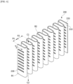
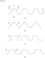
- FIGS. 6 to 8 are views for describing one example of a heat sink.
- a heat conversion device 1000 includes a thermoelectric element 100, a first heat sink 200, a fan 300, a heat insulating member 400, a housing 500, and a second heat sink 600.
- the thermoelectric element 100 includes a lower substrate 110, lower electrodes 120, a P-type thermoelectric leg 130, an N-type thermoelectric leg 140, an upper electrode 150, and an upper substrate 160.
- the lower electrodes 120 are disposed between the lower substrate 110 and lower floor surfaces of the P-type thermoelectric leg 130 and the N-type thermoelectric leg 140, and the upper electrode 150 is disposed between the upper substrate 160 and upper floor surfaces of the P-type thermoelectric leg 130 and the N-type thermoelectric leg 140. Accordingly, a plurality of P-type thermoelectric legs 130 and a plurality of N-type thermoelectric legs 140 are electrically connected by lower electrodes 120 and upper electrodes 150.
- the pair of P-type thermoelectric leg 130 and N-type thermoelectric leg 140 which are disposed between the lower electrodes 120 and the upper electrode 150 and electrically connected to each other may form a unit cell.
- the substrate through which a current flows from the P-type thermoelectric leg 130 to the N-type thermoelectric leg 140 absorbs heat and thus serves as a cooling part, and the substrate through which a current flows from the N-type thermoelectric leg 140 to the P-type thermoelectric leg 130 is heated and thus serves as a heating part.
- the heat-absorbing surface may also be one surface of the substrate serving as the cooling part, and the heating surface may also be one surface of the substrate serving as the heating part.
- the P-type thermoelectric leg 130 and the N-type thermoelectric leg 140 may be bismuth-telluride (Bi-Te)-based thermoelectric legs mainly including bismuth (Bi) and tellurium (Te).
- the P-type thermoelectric leg 130 may be a thermoelectric leg including a Bi-Te-based main material containing at least one among antimony (Sb), nickel (Ni), aluminum (Al), copper (Cu), silver (Ag), lead (Pb), boron (B), gallium (Ga), tellurium (Te), bismuth (Bi), and indium (In) in the range of 99 to 99.999 wt% and a mixture containing Bi or Te in the range of 0.001 to 1 wt% based on a total weight of 100 wt%.
- a main material of the P-type thermoelectric leg 130 may be Bi-selenium (Se)-Te, and the P-type thermoelectric leg 130 may further include Bi or Te in the range of 0.001 to 1 wt% based on a total weight.
- the N-type thermoelectric leg 140 may be a thermoelectric leg including a Bi-Te-based main material containing at least one among Se, Ni, Cu, Ag, Pb, B, Ga, Te, Bi, and In in the range of 99 to 99.999 wt% and a mixture containing Bi or Te in the range of 0.001 to 1 wt% based on a total weight of 100 wt%.
- a main material of the N-type thermoelectric leg 140 may be Bi-Sb-Te, and the N-type thermoelectric leg 140 may further include Bi or Te in the range of 0.001 to 1 wt% based on a total weight.
- the P-type thermoelectric leg 130 and the N-type thermoelectric leg 140 may be formed in a bulk type or a stacked type.
- the bulk type P-type thermoelectric leg 130 or the bulk type N-type thermoelectric leg 140 may be formed by performing a thermal process on a thermoelectric material to manufacture an ingot, grinding and straining the ingot to obtain a powder for a thermoelectric leg, sintering the powder, and cutting a sintered body.
- the stacked type P-type thermoelectric leg 130 or the stacked type N-type thermoelectric leg 140 may be formed by coating a sheet-shaped base with a paste including a thermoelectric material to form unit members, stacking the unit members, and cutting the stacked unit members.
- the pair of P-type thermoelectric leg 130 and N-type thermoelectric leg 140 may have the same shape and volume or may have different shapes and volumes.
- a height or cross sectional area of the N-type thermoelectric leg 140 may be different from that of the P-type thermoelectric leg 130.
- thermoelectric element The performance of the thermoelectric element according to one embodiment of the present invention may be expressed as a Seebeck index.
- ⁇ is the Seebeck coefficient [V/K]
- ⁇ is electric conductivity [S/m]
- ⁇ 2• ⁇ is a power factor [W/mK2].
- T is temperature
- k is thermal conductivity [W/mK]. k may be expressed as a•cp• ⁇ , wherein a is thermal diffusivity [cm2/S], cp is specific heat [J/gK], and ⁇ is density [g/cm3].
- a Z value [V/K] is measured using a Z meter, and then, the Seebeck index (ZT) may be calculated using the measured Z value.
- each of the lower electrodes 120 disposed between the lower substrate 110 and the P-type thermoelectric leg 130 and between the lower substrate 110 and the N-type thermoelectric leg 140, and the upper electrode 150 disposed between the upper substrate 160 and the P-type thermoelectric leg 130 and between the upper substrate 160 and the N-type thermoelectric leg 140 may include at least one among Cu, Ag, and Ni and may have a thickness in the range of 0.01 mm to 0.3 mm. In a case in which a thickness of the lower electrode 120 or the upper electrode 150 is less than 0.01 mm, an electrode function thereof is degraded so that electric conductivity performance thereof may be lowered, and in a case in which the thickness thereof is greater than 0.3 mm, resistance thereof increases so that conduction efficiency thereof may be lowered.
- the lower substrate 110 and the upper substrate 160 which face each other may be insulating substrates or metal substrates.
- the insulating substrate may be an alumina substrate or flexible polymer resin substrate.
- the flexible polymer resin substrate may include any insulating resin material such as high permeability plastics including polyimide (PI), polystyrene (PS), poly methyl methacrylate (PMMA), a cyclic olefin copolymer (COC), polyethylene terephthalate (PET), or a resin.
- the metal substrate may include Cu, a Cu alloy, or a Cu-Al alloy, and a thickness thereof may be in the range of 0.1 mm to 0.5 mm.
- the thickness of the metal substrate is less than 0.1 mm or greater than 0.5 mm, since a heat dissipation property or thermal conductivity thereof may become excessively high, the reliability of the thermoelectric element may be lowered.
- dielectric layers 170 may be further formed between the lower substrate 110 and the lower electrodes 120 and between the upper substrate 160 and the upper electrode 150.
- the dielectric layer 170 may include a material having a thermal conductivity in the range of 5 to 10 W/K and may have a thickness in the range of 0.01 mm to 0.15 mm.
- the thickness of the dielectric layer 170 is less than 0.01 mm, insulating efficiency or a withstanding voltage property may be lowered, and in a case in which the thickness thereof is greater than 0.15 mm, thermal conductivity is lowered so that heat dissipation efficiency may be lowered.
- sizes of the lower substrate 110 and the upper substrate 160 may also be different.
- a volume, a thickness, or an area of one of the lower substrate 110 and the upper substrate 160 may be greater than that of the other. Accordingly, the heat absorption or dissipation performance of the thermoelectric element can be enhanced.
- a heat dissipation pattern for example, an irregular pattern
- the irregular pattern is formed on a surface in contact with the P-type thermoelectric leg 130 or N-type thermoelectric leg 140, a bonding property between the thermoelectric leg and the substrate can also be improved.
- the P-type thermoelectric leg 130 or N-type thermoelectric leg 140 may have a cylindrical form, a polygonal column form, an elliptical column form, or the like.
- a width of a portion, which is bonded to the electrode, of the P-type thermoelectric leg 130 or N-type thermoelectric leg 140 may be large.
- thermoelectric element 100 including the lower substrate 110, the lower electrodes 120, the P-type thermoelectric leg 130, the N-type thermoelectric leg 140, the upper electrode 150, and the upper substrate 160 are provided, but the present invention is not limited thereto.
- At least one of the lower substrate 110 and the upper substrate 160 may be omitted, and the heat sinks may also serve as the lower substrate 110 and the upper substrate 160.
- an insulating portion may also be further disposed between the heat sink and the lower electrodes 120 or between the heat sink and the upper electrode 150.
- the first heat sink 200 is disposed on one surface of the thermoelectric element 100, for example, disposed on a side of the heating surface, and the fan 300 is coupled to the first heat sink 200.
- the fan 300 may be a cooling fan.
- the fan 300 may be used with an air conditioner.
- the second heat sink 600 is disposed on another surface of the thermoelectric element 100, for example, disposed on a side of the heat-absorbing surface.
- the heat insulating member 400 may be further disposed between the thermoelectric element 100 and the second heat sink 600, and both of the thermoelectric element 100 and the heat insulating member 400 may be accommodated in the housing 500.
- a plurality of flat base members having flat plate forms are disposed to be parallel to each other and may have a structure in which spaces between the flat base members form air flow paths.
- the first heat sink 200 may include at least one flow path pattern 200A forming an air flow path C1 using a base member including a first flat surface 210 and a second flat surface 220 and formed as a flat plate.
- the flow path pattern 200A may have a structure in which the base member is folded to form a curvature pattern having predetermined pitches P1 and P2 and a predetermined height T1, that is, a folded structure.
- air comes into surface-contact with the first flat surface 210 and the second flat surface 220 of the first heat sink 200, and an area in surface-contact with the air may be maximized by the flow path pattern 200A.
- the air may move while uniformly coming into contact with the first flat surface 210 and the second flat surface 220 and move in a flow path direction C2. Accordingly, since a contact surface is large when compared to a base member having a simple flat plate form, a heat-absorbing or heating effect is improved.
- a protrusion type resistive pattern 230 may also be formed on the base member.
- the resistive pattern 230 may be formed to have a protruding structure inclined at a predetermined inclination angle ⁇ in a direction in which air is introduced. Accordingly, since friction between the resistive pattern 230 and the air may be maximized, a contact surface can be increased or contact efficiency can be improved.
- a groove 240 may also be formed in a surface in front of the resistive pattern 230 of the base member. Since some amount of air coming into contact with the resistive pattern 230 passes through the groove 240 and moves between a front surface and a rear surface of the base member, a contact area can be further increased or contact efficiency can be further improved.
- the resistive pattern 230 is illustrated to be formed on the first flat surface 210 but is not limited thereto and may also be formed on the second flat surface 220.
- a flow path pattern may have various modified examples.
- a pattern having a curvature may be repeated with a predetermined pitch P1 as illustrated in FIG. 8A
- a pattern having a cutting edge portion may be repeated as illustrated in FIG. 8B
- unit patterns may also have polygonal shapes as illustrated in FIG. 8C and 8D .
- a resistive pattern may also be formed on each of surfaces B1 and B2 of the patterns.
- the flow path pattern has a predetermined cycle and a height but is not limited thereto and the cycle and the height T1 of the flow path pattern may be non-uniformly changed.
- FIGS. 6 to 8 one example of the first heat sink 200 is illustrated for the sake of convenience in the description, and a structure of the first heat sink 200 included in the heat conversion device according to the embodiment of the present invention may be variously modified.
- the first heat sink 200 and the fan 300 may be disposed to be spaced apart by a predetermined distance.
- the first heat sink 200 and the fan 300 may have elasticity, and the first heat sink 200 and the fan 300 are fixed using a plurality of coupling members 700 which fix the first heat sink 200 to the fan 300.
- the first heat sink 200 and the fan 300 are disposed to be spaced apart by the predetermined distance, since a problem of transmitting vibration generated when the fan 300 rotates to the first heat sink 200 is minimized, vibration and noise of the first heat sink 200 can be prevented.
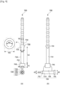
- FIG. 9 is a view illustrating the coupling member included in the heat conversion device according to one embodiment of the present invention
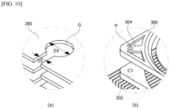
- FIG. 10 is a view illustrating a part of the heat sink and a part of the fan which is coupled to the coupling member according to one embodiment of the present invention
- FIG. 9A is a side view illustrating the coupling member
- FIG. 9B is a side view illustrating the coupling member turned by 90° from FIG. 9A .
- the coupling member 700 includes a shaft 710, a first fixing portion 720 disposed at one end of the shaft 710 and fixed to the first heat sink 200, a second fixing portion 730 protruding from an outer circumferential surface of the shaft 710 and fixed to the fan 300, and a separating portion 740 which protrudes from the outer circumferential surface of the shaft 710, is disposed between the first heat sink 200 and the fan 300, and separates the first heat sink 200 from the fan 300.
- the shaft 710, the first fixing portion 720, the second fixing portion 730, and the separating portion 740 are integrally formed from a silicone resin.
- an elastic modulus of the coupling member 700 is range from 1*10 3 kgf/cm 2 to 30*10 3 kgf/cm 2 , and a hardness thereof ranges from 40 to 90 Hs.
- a unit of hardness may be Shore hardness, and Shore hardness may be measured using a rebounded height when a falling object to which a diamond is fixed to an end portion thereof falls from a predetermined height. Accordingly, the coupling member 700 can fix the first heat sink 200 and the fan 300.
- the first fixing portion 720 is a portion fixed to the first heat sink 200, and to this end, grooves G for fixing the first fixing portion 720 is formed in the first heat sink 200.
- the first fixing portion 720 includes a front end region 722, a middle region 724, a rear end region 726, and a connecting region 728.
- the front end region 722, the middle region 724, and the rear end region 726 are integrally formed to have a cylindrical or oval column form.
- a diameter d1 of the front end region 722 is less than a diameter d2 of the middle region 724
- the diameter d2 of the middle region 724 is less than a diameter d3 of the rear end region 726.
- the groove G formed in the first heat sink 200 has a form which is configured to accommodate the middle region 724 of the first fixing portion 720, the diameter d1 of the front end region 722 of the first fixing portion 720 is less than a diameter D1 of the groove G formed in the first heat sink 200, the diameter d2 of the middle region 724 is 1 to 1.1 times the diameter D1 of the groove G formed in the first heat sink 200, and the diameter d3 of the rear end region 726 is greater than the diameter D1 of the groove G formed in the first heat sink 200.
- the middle region 724 has elasticity, even when the diameter d2 of the middle region 724 is 1 to 1.1 times the diameter D1 of the groove G formed in the first heat sink 200, the middle region 724 is inserted into the groove G. Accordingly, after the front end region 722 of the first fixing portion 720 starts to enter and enters the groove G formed in the first heat sink 200, a position of the coupling member 700 may be fixed using the rear end region 726. In this case, a step may be formed between the middle region 724 and the rear end region 726. Accordingly, after the middle region 724 of the first fixing portion 720 enters the groove G formed in the first heat sink 200, the middle region 724 may stop due to the rear end region 726.
- the rear end region 726 may be fixed to the groove G formed in the first heat sink 200.
- the rear end region 726 may be disposed in a periphery of the groove G or may also be fixed between radiation fins of the first heat sink 200.
- the connecting region 728 of the first fixing portion 720 may connect the middle region 724 and the separating portion 740 and may have a plate form of which a thickness is less than the diameter of the middle region 724.
- the groove G formed in the first heat sink 200 may further include a region through which the connecting region 728 of the first fixing portion 720 passes.
- a width D2 of the region through which the connecting region 728 of the first fixing portion 720 passes may be the same as the thickness of the connecting region 728 or may be 0.9 to 1.1 times the thickness of the connecting region 728, and the width D2 may be less than the diameter D1 of the groove G. Accordingly, after the middle region 724 of the first fixing portion 720 is accommodated in the groove G formed in the first heat sink 200, the middle region 724 may not be departed to the outside.
- the second fixing portion 730 is a portion fixed to the fan 300, and to this end, the fan 300 includes holes H through which each shaft 710 of the coupling members 700 pass.
- the fan 300 includes holes H through which each shaft 710 of the coupling members 700 pass.
- two flat plates facing each other and spaced apart from each other are disposed at an edge of the fan 300, and the holes H are formed in each of two flat plates to correspond to each other.
- a width W of the second fixing portion 730 increases in a direction toward the first fixing portion 720. That is, the width of the second fixing portion 730 has a circular truncated cone form, and one surface 732 of the second fixing portion 730 is in contact with the fan 300.
- a width W2 of the one surface 732 of the second fixing portion 730 ranges from 120 to 180%, preferably ranges from 130 to 170%, and more preferably ranges from 140 to 160% of a diameter of the hole H formed in the fan 300
- a width W1 of the other surface 734 opposite to the one surface 732 ranges from 50 to 80%, preferably ranges from 55 to 75%, and more preferably ranges from 60 to 70% of the diameter of the hole H formed in the fan 300.
- the second fixing portion 730 may be fixed to the fan 300.
- the one surface 732, which has the width greater than the diameter of the hole H, of the second fixing portion 730 can pass through the hole H.
- the second fixing portion 730 has the circular truncated cone form including at least one groove formed in the one surface 732.
- the second fixing portion 730 may has a conical form of which an upper end portion is truncated.
- At least a part, from which the second fixing portion 730 protrudes, in the shaft 710 may be empty.
- a volume of an empty space between the second fixing portion 730 and the shaft 710 or a volume of an empty space in the shaft 710 from which the second fixing portion 730 protrudes may range from 1/3 to 2/3 of a volume of a circular truncated cone defined by upper, floor, and side surfaces of the second fixing portion 730.
- a height of the empty space between the second fixing portion 730 and the shaft 710 or a height of the empty space in the shaft 710 from which the second fixing portion 730 protrudes may be 1/3 to 2/3 of a height of the circular truncated cone defined by the upper, floor, and side surfaces of the second fixing portion 730.
- the form of the empty space between the second fixing portion 730 and the shaft 710 may be a conical form, and the form of the empty space in the shaft 710 from which the second fixing portion 730 protrudes may be a cylindrical form.
- the separating portion 740 protrudes from the shaft 710 and is connected to the connecting region 728 of the first fixing portion 720.
- the separating portion 740 has a cylindrical form or prism form, and a width of the separating portion 740 is greater than the diameter of the hole H formed in the fan 300. Accordingly, the separating portion 740 serves to separate the first heat sink 200 from the fan 300 by a predetermined distance.
- the separating portion 740 has the cylindrical form or prism form, one of an upper surface and a lower surface is in direct contact with the first heat sink 200, and the other one of the upper surface and the lower surface is in direct contact with the fan 300.
- Diameters of the upper surface and the lower surface of the separating portion 740 are greater than the diameter D2 of the groove G formed in the first heat sink 200 and the diameter of the hole H formed in the fan 300. Accordingly, the separating portion 740 stably maintains the predetermined distance, which corresponds to a height of the separating portion 740, between the first heat sink 200 and the fan 300.
- a height h1 of the separating portion 740 may range from 1 to 10 mm and may preferably range from 2 to 8 mm.
- noise may become large.
- the height of the separating portion 740 is less than 1 mm, cooling efficiency is high, but there is a problem of high noise.
- the height of the separating portion 740 is greater than 10 mm, noise is small, but there is a problem of low cooling efficiency.
- a distance h2 between the second fixing portion 730 and the separating portion 740 ranges from 0.9 to 1 times a height of the fan 300. Accordingly, the one surface 742 of the separating portion 740 is fixed to a lower periphery 302 of the hole H formed in the fan 300, and the one surface 732 of the second fixing portion 730 is fixed to an upper periphery 304 of the hole H formed in the fan 300 so that the first heat sink 200 and the fan 300 is stably coupled.
- the coupling member 700 according to the embodiment of the present invention has elasticity, even though the distance h2 between the second fixing portion 730 and the separating portion 740 ranges from 0.9 to 1 times the height of the fan 300, the one surface 742 of the separating portion 740 is fixed to the lower periphery 302 of the hole H formed in the fan 300, and the one surface 732 of the second fixing portion 730 is fixed to the upper periphery 304 of the hole H formed in the fan 300.
- the plurality of coupling members 700 for example, two, preferably three, and more preferably four coupling members, are couple the first heat sink 200 and the fan 300.
- the plurality of grooves G formed in the first heat sink 200 corresponds to positions of the plurality of holes H formed in the fan 300.
- FIGS. 11 to 13 are views showing a process in which the first heat sink and the fan are coupled using the coupling member according to one embodiment of the present invention.
- the first fixing portion 720 formed on one end of the shaft 710 of the coupling member 700 passes through the groove G formed in the first heat sink 200.
- the first fixing portion 720 may be inserted into a wall surface of the first heat sink 200 as illustrated in FIG. 12 , or the first fixing portion 720 may also be inserted into a middle of the first heat sink 200 as illustrated in FIG. 13 .
- the other end portion of the shaft 710 of the coupling member 700 passes through the hole H formed in the fan 300.
- the coupling member 700 may stably couple the first heat sink 200 and the fan 300.
- the other end portion of the shaft 710 of the coupling member 700 is cut.
- the other end portion of the shaft 710 has a structure longitudinally extending from the second fixing portion 730 and an extending portion is cut after the process of FIG. 11B , the first heat sink 200 and the fan 300 is easily coupled.
- the process of FIGS. 11A to 11C may be repeated a plurality of times, for example, two or more, preferably three or more, and more preferably four or more times.
- the first heat sink 200 and the fan 300 can be more stably coupled.
- a coupling member may also include a plurality of second fixing portions.
- FIG. 14 is a side view illustrating the coupling member according to another embodiment of the present invention.
- a plurality of second fixing portions 730 may be disposed to be spaced a predetermined distance from each other.
- the plurality of second fixing portions 730 are illustrated to have the same size but are not limited thereto.
- the plurality of second fixing portions 730 may have various sizes.
- a coupling member 700 may be commonly used for a fan 300 having any height or including holes having various sizes.
- Tables 1 to 7 show experimental results of cooling temperature and noise according to a spaced distance between a first heat sink and a fan.
- Tables 1 to 7 are results of temperature measurements at one point of a heat-absorbing portion (heat-absorbing portion #1) and another point of the heat-absorbing portion (temperature heat-absorbing portion #2), which are performed on ten samples each having spaced distances of 0 mm, 1 mm, 4 mm, 6 mm, 8 mm, 10 mm, and 12 mm. In this case, the spaced distance is adjusted using a height of a separating portion.
- thermoelectric module in the case in which the spaced distance between the first heat sink and the fan was 0 mm, cooling efficiency was high, but there was a problem of high noise. In addition, in the case in which the spaced distance between the first heat sink and the fan was 12 mm, noise was low, but there was a problem of low cooling efficiency. However, in the case in which the spaced distance between the first heat sink and the fan ranged from 1 to 10 mm or less and preferably ranged from 2 to 8 mm or less according to the embodiment of the present invention, a thermoelectric module can be obtained which had high cooling efficiency and low noise.
- thermoelectric element according to the embodiment of the present invention can be applied to power generation devices, cooling devices, heating devices, waste heat utilization devices, and the like.
- thermoelectric element according to the embodiment of the present invention is mainly applicable to optical communication modules, sensors, medical devices, measuring instruments, aerospace industry, refrigerators, chillers, automotive ventilation sheets, cup holders, washing machines, dryers, wine cellars, water purifiers, sensor power supplies, thermopiles, and the like.
- thermoelectric element according to the embodiment of the present invention is applied to a medical device.
- the PCR device is for amplifying a deoxyribonucleic acid (DNA) to determine a DNA sequence and requires precise temperature control and thermal cycle.
- a Peltier-based thermoelectric element can be applied to the PCR device.
- thermoelectric element is another example in which the thermoelectric element according to the embodiment of the present invention is applied to a medical device.
- the photodetector includes an infrared/ultraviolet detector, a charge coupled device (CCD) sensor, an X-ray detector, and a thermoelectric thermal reference source (TTRS), and the like.
- CCD charge coupled device
- TTRS thermoelectric thermal reference source
- a Peltier-based thermoelectric element can be applied to cool the photodetector. Accordingly, a wavelength change, output degradation, resolution degradation, and the like due to an increase in a temperature in the photodetector can be prevented.
- thermoelectric element according to the embodiment of the present invention is applied to a medical device. Accordingly, more precise temperature control can be performed.
- thermoelectric element according to the embodiment of the present invention is applied to a medical device. Accordingly, power can be supplied to the artificial heart.
- thermoelectric element according to the embodiment of the present invention is applied to an aerospace industry
- examples in which the thermoelectric element according to the embodiment of the present invention is applied to an aerospace industry include star tracking systems, heat imaging cameras, infrared/ultraviolet detectors, CCD sensors, the Hubble Space Telescope, TTRSs. Accordingly, a temperature of an imaging sensor can be maintained.
- thermoelectric element according to the embodiment of the present invention can be applied for generating electricity, cooling, and heating in the other industry fields.
Landscapes
- Engineering & Computer Science (AREA)
- Physics & Mathematics (AREA)
- Mechanical Engineering (AREA)
- Thermal Sciences (AREA)
- General Engineering & Computer Science (AREA)
- Cooling Or The Like Of Electrical Apparatus (AREA)
- Cooling Or The Like Of Semiconductors Or Solid State Devices (AREA)
Claims (10)
- Wärmeumwandlungsvorrichtung, umfassend:ein Element (100);einen Kühlkörper (200), der an dem Element (100) angeordnet ist;einen Lüfter (300), der angeordnet ist, um einen vorbestimmten Abstand von dem Kühlkörper (200) entfernt zu sein; undeine Vielzahl von Kopplungsgliedern (700), die aus einem Silikonharz einstückig ausgebildet sind und die einen Elastizitätsmodul aufweisen, der von 1*103 kgf/cm2 bis 30*103 kgf/cm2 reicht, und den Kühlkörper (200) und den Lüfter (300) befestigen,wobei jedes der Kopplungsglieder (700) eine Welle (710) einschließt,einen ersten Befestigungsabschnitt (720), der an einem Ende der Welle (710) angeordnet und an dem Kühlkörper (200) befestigt ist,einen zweiten Befestigungsabschnitt (730), der von einer äußeren Umfangsoberfläche der Welle (710) vorsteht und an dem Lüfter (300) befestigt ist, undeinen Trennabschnitt (740), der zwischen dem ersten Befestigungsabschnitt (720) und dem zweiten Befestigungsabschnitt (730) angeordnet ist,wobei der Trennabschnitt (740) zwischen dem Kühlkörper (200) und dem Lüfter (300) angeordnet ist, undwobei die Welle (710), der erste Befestigungsabschnitt (720), der zweite Befestigungsabschnitt (730) und der Trennabschnitt (740) einstückig ausgebildet sind,wobei der Lüfter (300) ein Loch einschließt, durch das die Welle (710) hindurchgeht,wobei eine erste Oberfläche (742) des Trennabschnitts (740) mit einem ersten Umfang des Lochs in Berührung steht,wobei eine erste Oberfläche (732) des zweiten Befestigungsabschnitts (730) mit einem zweiten Umfang des Lochs in Berührung steht,wobei eine Breite jeder der ersten Oberfläche (742) des Trennabschnitts (740) und der ersten Oberfläche (732) des zweiten Befestigungsabschnitts (730) größer als ein Durchmesser des Lochs ist, undwobei ein Abstand zwischen der ersten Oberfläche (742) des Trennabschnitts (740) und der ersten Oberfläche (732) des zweiten Befestigungsabschnitts (730) von 0,9 bis 1 Mal einer Höhe des Lüfters (300) reicht,wobeieine Nut (G) zum Fixieren des ersten Befestigungsabschnitts (720) in dem Kühlkörper (200) ausgebildet ist, dadurch gekennzeichnet, dass das Element (100) ein thermoelektrisches Element ist, undder erste Befestigungsabschnitt (720) einen vorderen Endbereich (722), der einen ersten Durchmesser (d1) aufweist, einen mittleren Bereich (724), der einen zweiten Durchmesser (d2) aufweist, und einen hinteren Endbereich (726) einschließt, der einen dritten Durchmesser (d3) aufweist, der größer als der zweite Durchmesser (d2) ist,der erste Durchmesser (d1) des vorderen Endbereichs (722) kleiner als ein Durchmesser (D1) der Nut (G) ist, der zweite Durchmesser (d2) des mittleren Bereichs (724) 1 bis 1,1 Mal der Durchmesser (D1) der Nut (G) ist, undder dritte Durchmesser (d3) des hinteren Endbereichs (726) größer als der Durchmesser (D1) der Nut (G) ist.
- Wärmeumwandlungsvorrichtung nach Anspruch 1, wobei:die Breite der ersten Oberfläche (732) des zweiten Befestigungsabschnitts (730) von 120 bis 180 % des Durchmessers des Lochs reicht; undeine Breite einer zweiten Oberfläche (734), die der ersten Oberfläche (732) des zweiten Befestigungsabschnitts (730) gegenüberliegt, des zweiten Befestigungsabschnitts (730) von 50 bis 80 % des Durchmessers des Lochs reicht.
- Wärmeumwandlungsvorrichtung nach Anspruch 1, wobei mindestens ein Teil zwischen dem zweiten Befestigungsabschnitt (730) und der Welle (710) hohl ist.
- Wärmeumwandlungsvorrichtung nach Anspruch 3, wobei der zweite Befestigungsabschnitt (730) eine kreisförmige kegelstumpfförmige Form aufweist, die mindestens eine Nut einschließt, die in einer unteren Oberfläche davon ausgebildet ist.
- Wärmeumwandlungsvorrichtung nach Anspruch 1, wobei mindestens ein Teil in der Welle (710), von dem der zweite Befestigungsabschnitt (730) vorsteht, hohl ist.
- Wärmeumwandlungsvorrichtung nach Anspruch 1, wobei die Kopplungsglieder (700) eine Shore-Härte aufweisen, die von 40 bis 90 Hs reicht.
- Wärmeumwandlungsvorrichtung nach Anspruch 1, wobei eine Höhe des Trennabschnitts (740) 1 bis 10 mm beträgt.
- Wärmeumwandlungsvorrichtung nach Anspruch 7, wobei der mittlere Bereich (724) eine zylindrische Form aufweist und der mittlere Bereich (724) in die Nut (G) eingesetzt ist.
- Wärmeumwandlungsvorrichtung nach Anspruch 8, wobei der erste Befestigungsabschnitt (720) ferner einen Verbindungsbereich (728) einschließt, der den mittleren Bereich (724) und den Trennabschnitt (740) verbindet,wobei der Verbindungsbereich (728) eine Plattenform ist, deren Dicke kleiner als ein Durchmesser des mittleren Bereichs (724) ist, unddie Nut (G) einen Bereich einschließt, durch den der Verbindungsbereich (728) hindurchgeht.
- Wärmeumwandlungsvorrichtung nach Anspruch 9, wobei eine Breite (D2) des Bereichs, durch den der Verbindungsbereich (728) hindurchgeht, gleich der Dicke des Verbindungsbereichs (728) ist oder größer als die Dicke des Verbindungsbereichs (728) ist und kleiner als ein Durchmesser (D1) der Nut (G) ist.
Applications Claiming Priority (2)
| Application Number | Priority Date | Filing Date | Title |
|---|---|---|---|
| KR1020170071492A KR101920776B1 (ko) | 2017-06-08 | 2017-06-08 | 열변환장치 |
| PCT/KR2018/006477 WO2018226044A1 (ko) | 2017-06-08 | 2018-06-07 | 열변환장치 |
Publications (3)
| Publication Number | Publication Date |
|---|---|
| EP3637019A1 EP3637019A1 (de) | 2020-04-15 |
| EP3637019A4 EP3637019A4 (de) | 2021-03-24 |
| EP3637019B1 true EP3637019B1 (de) | 2024-03-06 |
Family
ID=64566202
Family Applications (1)
| Application Number | Title | Priority Date | Filing Date |
|---|---|---|---|
| EP18812847.4A Active EP3637019B1 (de) | 2017-06-08 | 2018-06-07 | Wärmeumwandlungsvorrichtung |
Country Status (5)
| Country | Link |
|---|---|
| US (1) | US11227987B2 (de) |
| EP (1) | EP3637019B1 (de) |
| KR (1) | KR101920776B1 (de) |
| CN (1) | CN110730890B (de) |
| WO (1) | WO2018226044A1 (de) |
Families Citing this family (1)
| Publication number | Priority date | Publication date | Assignee | Title |
|---|---|---|---|---|
| US12594557B2 (en) | 2019-08-12 | 2026-04-07 | Intabio, Llc | Isoelectric focusing devices and fixtures |
Citations (1)
| Publication number | Priority date | Publication date | Assignee | Title |
|---|---|---|---|---|
| US20100002389A1 (en) * | 2008-07-01 | 2010-01-07 | Xigmatek Co., Ltd. | Fan fastener |
Family Cites Families (33)
| Publication number | Priority date | Publication date | Assignee | Title |
|---|---|---|---|---|
| JP3069819B2 (ja) * | 1992-05-28 | 2000-07-24 | 富士通株式会社 | ヒートシンク並びに該ヒートシンクに用いるヒートシンク取付具及びヒートシンクを用いた可搬型電子装置 |
| CN2219469Y (zh) * | 1994-12-03 | 1996-02-07 | 华中理工大学 | 热电致冷饮料机 |
| US5896917A (en) * | 1996-02-22 | 1999-04-27 | Lemont Aircraft Corporation | Active heat sink structure with flow augmenting rings and method for removing heat |
| JP2000031677A (ja) | 1998-07-09 | 2000-01-28 | Matsushita Electric Ind Co Ltd | 冷却ファンの取付装置及び取付方法ならびにそれに用いるコイルばね押圧拡径取付治具 |
| US7584780B1 (en) * | 1998-12-09 | 2009-09-08 | Lemont Aircraft Corporation | Active heat sink structure with flow augmenting rings and method for removing heat |
| JP2001165525A (ja) * | 1999-12-07 | 2001-06-22 | Seiko Seiki Co Ltd | 熱電加熱冷却装置 |
| JP2001162255A (ja) * | 1999-12-07 | 2001-06-19 | Denso Corp | 生ごみ処理装置 |
| US6530231B1 (en) * | 2000-09-22 | 2003-03-11 | Te Technology, Inc. | Thermoelectric assembly sealing member and thermoelectric assembly incorporating same |
| KR200226141Y1 (ko) | 2000-12-06 | 2001-06-01 | 엘지전자주식회사 | 발열칩용 냉각팬 고정장치 |
| CN100541104C (zh) * | 2003-12-15 | 2009-09-16 | 臼井国际产业株式会社 | 热交换器 |
| CN2763757Y (zh) * | 2005-01-13 | 2006-03-08 | 湖南凯尔半导体致冷有限公司 | 半导体大功率致冷装置 |
| DE202005007211U1 (de) * | 2005-05-06 | 2005-08-04 | Heine Optotechnik Gmbh & Co. Kg | Beleuchtungsvorrichtung |
| KR20070029508A (ko) * | 2005-09-09 | 2007-03-14 | 주식회사 대우일렉트로닉스 | 냉각팬의 소음 저감 체결 구조 |
| CN2849963Y (zh) * | 2005-12-01 | 2006-12-20 | 张雷兵 | 半导体致冷散热装置 |
| US7537429B2 (en) * | 2006-04-06 | 2009-05-26 | Fu Zhun Precision Industry (Shen Zhen) Co., Ltd. | Fan fastener for fastening a fan to a heat sink and method of using the same |
| CN200941730Y (zh) * | 2006-08-21 | 2007-08-29 | 英业达股份有限公司 | 散热装置的防震机构 |
| CN201228671Y (zh) * | 2008-05-28 | 2009-04-29 | 富钧科技股份有限公司 | 固设于散热器风扇的多段式弹性连接件 |
| CN101344350A (zh) * | 2008-09-03 | 2009-01-14 | 贵州贵航汽车零部件股份有限公司 | 半导体换热器 |
| KR100926901B1 (ko) * | 2009-01-09 | 2009-11-17 | 지에스제이주식회사 | 산소캡슐용 냉각장치 |
| KR200457138Y1 (ko) * | 2009-03-11 | 2011-12-07 | 이더테크놀로지(주) | 진동이 없는 칩셋 냉각용 방열 장치 |
| US20100242523A1 (en) | 2009-03-31 | 2010-09-30 | Todd Rubright | Electric Cooling System for Electronic Equipment |
| KR102010975B1 (ko) * | 2012-10-31 | 2019-10-21 | 웅진코웨이 주식회사 | 방열구조 및 이를 구비하는 냉수탱크 |
| US20140209273A1 (en) * | 2013-01-30 | 2014-07-31 | Silverstone Technology Co., Ltd. | Buckle and heat dissipation module having the same |
| EP2762994A1 (de) | 2013-02-04 | 2014-08-06 | SilverStone Technology Co., Ltd. | Schnalle und Modul zur Wärmeableitung damit |
| JP6271184B2 (ja) * | 2013-08-14 | 2018-01-31 | 竹内工業株式会社 | ヒートシンク保持装置 |
| CN203943523U (zh) * | 2014-04-28 | 2014-11-19 | 广东新创意科技有限公司 | 一种半导体制冷饮水机 |
| CN104236157A (zh) * | 2014-09-30 | 2014-12-24 | 博奥赛斯(天津)生物科技有限公司 | 一种制冷装置 |
| CN105444462B (zh) * | 2015-12-24 | 2018-01-26 | 广东富信科技股份有限公司 | 半导体制冷系统 |
| WO2018174468A1 (ko) * | 2017-03-21 | 2018-09-27 | 엘지전자 주식회사 | 냉장고 |
| KR102467404B1 (ko) | 2017-03-21 | 2022-11-16 | 엘지전자 주식회사 | 냉장고 |
| CN206944790U (zh) * | 2017-06-28 | 2018-01-30 | 杨柳 | 一种用于农业机械散热器的减振装置 |
| KR102462679B1 (ko) * | 2018-03-09 | 2022-11-04 | 엘지전자 주식회사 | 냉장고 |
| KR102420992B1 (ko) * | 2018-03-13 | 2022-07-15 | 엘지전자 주식회사 | 냉장고 |
-
2017
- 2017-06-08 KR KR1020170071492A patent/KR101920776B1/ko active Active
-
2018
- 2018-06-07 US US16/618,533 patent/US11227987B2/en active Active
- 2018-06-07 EP EP18812847.4A patent/EP3637019B1/de active Active
- 2018-06-07 CN CN201880038223.3A patent/CN110730890B/zh active Active
- 2018-06-07 WO PCT/KR2018/006477 patent/WO2018226044A1/ko not_active Ceased
Patent Citations (1)
| Publication number | Priority date | Publication date | Assignee | Title |
|---|---|---|---|---|
| US20100002389A1 (en) * | 2008-07-01 | 2010-01-07 | Xigmatek Co., Ltd. | Fan fastener |
Also Published As
| Publication number | Publication date |
|---|---|
| WO2018226044A1 (ko) | 2018-12-13 |
| US20200168780A1 (en) | 2020-05-28 |
| CN110730890A (zh) | 2020-01-24 |
| US11227987B2 (en) | 2022-01-18 |
| EP3637019A1 (de) | 2020-04-15 |
| KR101920776B1 (ko) | 2018-11-21 |
| CN110730890B (zh) | 2021-11-30 |
| EP3637019A4 (de) | 2021-03-24 |
Similar Documents
| Publication | Publication Date | Title |
|---|---|---|
| US20240357936A1 (en) | Thermoelectric element | |
| US11342490B2 (en) | Thermoelectric leg and thermoelectric element comprising same | |
| EP3745479B1 (de) | Thermoelektrisches element | |
| KR102359057B1 (ko) | 열전 소자 | |
| KR102275612B1 (ko) | 열전소자 | |
| EP3660416B1 (de) | Kühl-/wärmvorrichtung | |
| EP3637019A1 (de) | Wärmeumwandlungsvorrichtung | |
| CN112352324A (zh) | 热电元件 | |
| KR20180013146A (ko) | 컵 홀더 | |
| KR20190038103A (ko) | 열전소자 | |
| KR102511769B1 (ko) | 열전모듈 | |
| EP3690966B1 (de) | Thermoelektrische vorrichtung | |
| KR102509339B1 (ko) | 열전 소자 | |
| KR102221688B1 (ko) | 열변환장치 | |
| KR102478827B1 (ko) | 열전모듈 | |
| KR102358897B1 (ko) | 열전 소자 | |
| KR102310806B1 (ko) | 열전소자 | |
| KR102575215B1 (ko) | 열전소자 | |
| KR102055428B1 (ko) | 열전소자 | |
| KR20180000549A (ko) | 컵 홀더 | |
| KR20180089804A (ko) | 열전 소자 |
Legal Events
| Date | Code | Title | Description |
|---|---|---|---|
| STAA | Information on the status of an ep patent application or granted ep patent |
Free format text: STATUS: THE INTERNATIONAL PUBLICATION HAS BEEN MADE |
|
| PUAI | Public reference made under article 153(3) epc to a published international application that has entered the european phase |
Free format text: ORIGINAL CODE: 0009012 |
|
| STAA | Information on the status of an ep patent application or granted ep patent |
Free format text: STATUS: REQUEST FOR EXAMINATION WAS MADE |
|
| 17P | Request for examination filed |
Effective date: 20191205 |
|
| AK | Designated contracting states |
Kind code of ref document: A1 Designated state(s): AL AT BE BG CH CY CZ DE DK EE ES FI FR GB GR HR HU IE IS IT LI LT LU LV MC MK MT NL NO PL PT RO RS SE SI SK SM TR |
|
| AX | Request for extension of the european patent |
Extension state: BA ME |
|
| DAV | Request for validation of the european patent (deleted) | ||
| DAX | Request for extension of the european patent (deleted) | ||
| A4 | Supplementary search report drawn up and despatched |
Effective date: 20210224 |
|
| RIC1 | Information provided on ipc code assigned before grant |
Ipc: F25B 21/02 20060101AFI20210218BHEP Ipc: F28D 1/02 20060101ALI20210218BHEP Ipc: H01L 35/32 20060101ALI20210218BHEP |
|
| STAA | Information on the status of an ep patent application or granted ep patent |
Free format text: STATUS: EXAMINATION IS IN PROGRESS |
|
| 17Q | First examination report despatched |
Effective date: 20220919 |
|
| GRAP | Despatch of communication of intention to grant a patent |
Free format text: ORIGINAL CODE: EPIDOSNIGR1 |
|
| STAA | Information on the status of an ep patent application or granted ep patent |
Free format text: STATUS: GRANT OF PATENT IS INTENDED |
|
| RIC1 | Information provided on ipc code assigned before grant |
Ipc: H10N 10/17 20230101ALI20231116BHEP Ipc: F28D 1/02 20060101ALI20231116BHEP Ipc: F25B 21/02 20060101AFI20231116BHEP |
|
| INTG | Intention to grant announced |
Effective date: 20231205 |
|
| GRAS | Grant fee paid |
Free format text: ORIGINAL CODE: EPIDOSNIGR3 |
|
| GRAA | (expected) grant |
Free format text: ORIGINAL CODE: 0009210 |
|
| STAA | Information on the status of an ep patent application or granted ep patent |
Free format text: STATUS: THE PATENT HAS BEEN GRANTED |
|
| AK | Designated contracting states |
Kind code of ref document: B1 Designated state(s): AL AT BE BG CH CY CZ DE DK EE ES FI FR GB GR HR HU IE IS IT LI LT LU LV MC MK MT NL NO PL PT RO RS SE SI SK SM TR |
|
| REG | Reference to a national code |
Ref country code: GB Ref legal event code: FG4D |
|
| REG | Reference to a national code |
Ref country code: CH Ref legal event code: EP |
|
| REG | Reference to a national code |
Ref country code: DE Ref legal event code: R096 Ref document number: 602018066300 Country of ref document: DE |
|
| REG | Reference to a national code |
Ref country code: IE Ref legal event code: FG4D |
|
| REG | Reference to a national code |
Ref country code: LT Ref legal event code: MG9D |
|
| PG25 | Lapsed in a contracting state [announced via postgrant information from national office to epo] |
Ref country code: LT Free format text: LAPSE BECAUSE OF FAILURE TO SUBMIT A TRANSLATION OF THE DESCRIPTION OR TO PAY THE FEE WITHIN THE PRESCRIBED TIME-LIMIT Effective date: 20240306 |
|
| REG | Reference to a national code |
Ref country code: NL Ref legal event code: MP Effective date: 20240306 |
|
| PG25 | Lapsed in a contracting state [announced via postgrant information from national office to epo] |
Ref country code: GR Free format text: LAPSE BECAUSE OF FAILURE TO SUBMIT A TRANSLATION OF THE DESCRIPTION OR TO PAY THE FEE WITHIN THE PRESCRIBED TIME-LIMIT Effective date: 20240607 |
|
| PG25 | Lapsed in a contracting state [announced via postgrant information from national office to epo] |
Ref country code: HR Free format text: LAPSE BECAUSE OF FAILURE TO SUBMIT A TRANSLATION OF THE DESCRIPTION OR TO PAY THE FEE WITHIN THE PRESCRIBED TIME-LIMIT Effective date: 20240306 Ref country code: RS Free format text: LAPSE BECAUSE OF FAILURE TO SUBMIT A TRANSLATION OF THE DESCRIPTION OR TO PAY THE FEE WITHIN THE PRESCRIBED TIME-LIMIT Effective date: 20240606 |
|
| PG25 | Lapsed in a contracting state [announced via postgrant information from national office to epo] |
Ref country code: ES Free format text: LAPSE BECAUSE OF FAILURE TO SUBMIT A TRANSLATION OF THE DESCRIPTION OR TO PAY THE FEE WITHIN THE PRESCRIBED TIME-LIMIT Effective date: 20240306 |
|
| PG25 | Lapsed in a contracting state [announced via postgrant information from national office to epo] |
Ref country code: RS Free format text: LAPSE BECAUSE OF FAILURE TO SUBMIT A TRANSLATION OF THE DESCRIPTION OR TO PAY THE FEE WITHIN THE PRESCRIBED TIME-LIMIT Effective date: 20240606 Ref country code: NO Free format text: LAPSE BECAUSE OF FAILURE TO SUBMIT A TRANSLATION OF THE DESCRIPTION OR TO PAY THE FEE WITHIN THE PRESCRIBED TIME-LIMIT Effective date: 20240606 Ref country code: LT Free format text: LAPSE BECAUSE OF FAILURE TO SUBMIT A TRANSLATION OF THE DESCRIPTION OR TO PAY THE FEE WITHIN THE PRESCRIBED TIME-LIMIT Effective date: 20240306 Ref country code: HR Free format text: LAPSE BECAUSE OF FAILURE TO SUBMIT A TRANSLATION OF THE DESCRIPTION OR TO PAY THE FEE WITHIN THE PRESCRIBED TIME-LIMIT Effective date: 20240306 Ref country code: GR Free format text: LAPSE BECAUSE OF FAILURE TO SUBMIT A TRANSLATION OF THE DESCRIPTION OR TO PAY THE FEE WITHIN THE PRESCRIBED TIME-LIMIT Effective date: 20240607 Ref country code: FI Free format text: LAPSE BECAUSE OF FAILURE TO SUBMIT A TRANSLATION OF THE DESCRIPTION OR TO PAY THE FEE WITHIN THE PRESCRIBED TIME-LIMIT Effective date: 20240306 Ref country code: ES Free format text: LAPSE BECAUSE OF FAILURE TO SUBMIT A TRANSLATION OF THE DESCRIPTION OR TO PAY THE FEE WITHIN THE PRESCRIBED TIME-LIMIT Effective date: 20240306 Ref country code: BG Free format text: LAPSE BECAUSE OF FAILURE TO SUBMIT A TRANSLATION OF THE DESCRIPTION OR TO PAY THE FEE WITHIN THE PRESCRIBED TIME-LIMIT Effective date: 20240306 |
|
| REG | Reference to a national code |
Ref country code: AT Ref legal event code: MK05 Ref document number: 1663885 Country of ref document: AT Kind code of ref document: T Effective date: 20240306 |
|
| PG25 | Lapsed in a contracting state [announced via postgrant information from national office to epo] |
Ref country code: SE Free format text: LAPSE BECAUSE OF FAILURE TO SUBMIT A TRANSLATION OF THE DESCRIPTION OR TO PAY THE FEE WITHIN THE PRESCRIBED TIME-LIMIT Effective date: 20240306 Ref country code: LV Free format text: LAPSE BECAUSE OF FAILURE TO SUBMIT A TRANSLATION OF THE DESCRIPTION OR TO PAY THE FEE WITHIN THE PRESCRIBED TIME-LIMIT Effective date: 20240306 |
|
| PG25 | Lapsed in a contracting state [announced via postgrant information from national office to epo] |
Ref country code: NL Free format text: LAPSE BECAUSE OF FAILURE TO SUBMIT A TRANSLATION OF THE DESCRIPTION OR TO PAY THE FEE WITHIN THE PRESCRIBED TIME-LIMIT Effective date: 20240306 |
|
| PG25 | Lapsed in a contracting state [announced via postgrant information from national office to epo] |
Ref country code: NL Free format text: LAPSE BECAUSE OF FAILURE TO SUBMIT A TRANSLATION OF THE DESCRIPTION OR TO PAY THE FEE WITHIN THE PRESCRIBED TIME-LIMIT Effective date: 20240306 |
|
| PG25 | Lapsed in a contracting state [announced via postgrant information from national office to epo] |
Ref country code: IS Free format text: LAPSE BECAUSE OF FAILURE TO SUBMIT A TRANSLATION OF THE DESCRIPTION OR TO PAY THE FEE WITHIN THE PRESCRIBED TIME-LIMIT Effective date: 20240706 |
|
| PG25 | Lapsed in a contracting state [announced via postgrant information from national office to epo] |
Ref country code: SM Free format text: LAPSE BECAUSE OF FAILURE TO SUBMIT A TRANSLATION OF THE DESCRIPTION OR TO PAY THE FEE WITHIN THE PRESCRIBED TIME-LIMIT Effective date: 20240306 Ref country code: PT Free format text: LAPSE BECAUSE OF FAILURE TO SUBMIT A TRANSLATION OF THE DESCRIPTION OR TO PAY THE FEE WITHIN THE PRESCRIBED TIME-LIMIT Effective date: 20240708 |
|
| PG25 | Lapsed in a contracting state [announced via postgrant information from national office to epo] |
Ref country code: CZ Free format text: LAPSE BECAUSE OF FAILURE TO SUBMIT A TRANSLATION OF THE DESCRIPTION OR TO PAY THE FEE WITHIN THE PRESCRIBED TIME-LIMIT Effective date: 20240306 Ref country code: EE Free format text: LAPSE BECAUSE OF FAILURE TO SUBMIT A TRANSLATION OF THE DESCRIPTION OR TO PAY THE FEE WITHIN THE PRESCRIBED TIME-LIMIT Effective date: 20240306 |
|
| PG25 | Lapsed in a contracting state [announced via postgrant information from national office to epo] |
Ref country code: AT Free format text: LAPSE BECAUSE OF FAILURE TO SUBMIT A TRANSLATION OF THE DESCRIPTION OR TO PAY THE FEE WITHIN THE PRESCRIBED TIME-LIMIT Effective date: 20240306 |
|
| PG25 | Lapsed in a contracting state [announced via postgrant information from national office to epo] |
Ref country code: PL Free format text: LAPSE BECAUSE OF FAILURE TO SUBMIT A TRANSLATION OF THE DESCRIPTION OR TO PAY THE FEE WITHIN THE PRESCRIBED TIME-LIMIT Effective date: 20240306 |
|
| PG25 | Lapsed in a contracting state [announced via postgrant information from national office to epo] |
Ref country code: SK Free format text: LAPSE BECAUSE OF FAILURE TO SUBMIT A TRANSLATION OF THE DESCRIPTION OR TO PAY THE FEE WITHIN THE PRESCRIBED TIME-LIMIT Effective date: 20240306 |
|
| PG25 | Lapsed in a contracting state [announced via postgrant information from national office to epo] |
Ref country code: SM Free format text: LAPSE BECAUSE OF FAILURE TO SUBMIT A TRANSLATION OF THE DESCRIPTION OR TO PAY THE FEE WITHIN THE PRESCRIBED TIME-LIMIT Effective date: 20240306 Ref country code: SK Free format text: LAPSE BECAUSE OF FAILURE TO SUBMIT A TRANSLATION OF THE DESCRIPTION OR TO PAY THE FEE WITHIN THE PRESCRIBED TIME-LIMIT Effective date: 20240306 Ref country code: RO Free format text: LAPSE BECAUSE OF FAILURE TO SUBMIT A TRANSLATION OF THE DESCRIPTION OR TO PAY THE FEE WITHIN THE PRESCRIBED TIME-LIMIT Effective date: 20240306 Ref country code: PT Free format text: LAPSE BECAUSE OF FAILURE TO SUBMIT A TRANSLATION OF THE DESCRIPTION OR TO PAY THE FEE WITHIN THE PRESCRIBED TIME-LIMIT Effective date: 20240708 Ref country code: PL Free format text: LAPSE BECAUSE OF FAILURE TO SUBMIT A TRANSLATION OF THE DESCRIPTION OR TO PAY THE FEE WITHIN THE PRESCRIBED TIME-LIMIT Effective date: 20240306 Ref country code: IS Free format text: LAPSE BECAUSE OF FAILURE TO SUBMIT A TRANSLATION OF THE DESCRIPTION OR TO PAY THE FEE WITHIN THE PRESCRIBED TIME-LIMIT Effective date: 20240706 Ref country code: EE Free format text: LAPSE BECAUSE OF FAILURE TO SUBMIT A TRANSLATION OF THE DESCRIPTION OR TO PAY THE FEE WITHIN THE PRESCRIBED TIME-LIMIT Effective date: 20240306 Ref country code: CZ Free format text: LAPSE BECAUSE OF FAILURE TO SUBMIT A TRANSLATION OF THE DESCRIPTION OR TO PAY THE FEE WITHIN THE PRESCRIBED TIME-LIMIT Effective date: 20240306 Ref country code: AT Free format text: LAPSE BECAUSE OF FAILURE TO SUBMIT A TRANSLATION OF THE DESCRIPTION OR TO PAY THE FEE WITHIN THE PRESCRIBED TIME-LIMIT Effective date: 20240306 |
|
| PG25 | Lapsed in a contracting state [announced via postgrant information from national office to epo] |
Ref country code: IT Free format text: LAPSE BECAUSE OF FAILURE TO SUBMIT A TRANSLATION OF THE DESCRIPTION OR TO PAY THE FEE WITHIN THE PRESCRIBED TIME-LIMIT Effective date: 20240306 |
|
| REG | Reference to a national code |
Ref country code: DE Ref legal event code: R097 Ref document number: 602018066300 Country of ref document: DE |
|
| PG25 | Lapsed in a contracting state [announced via postgrant information from national office to epo] |
Ref country code: IT Free format text: LAPSE BECAUSE OF FAILURE TO SUBMIT A TRANSLATION OF THE DESCRIPTION OR TO PAY THE FEE WITHIN THE PRESCRIBED TIME-LIMIT Effective date: 20240306 |
|
| PLBE | No opposition filed within time limit |
Free format text: ORIGINAL CODE: 0009261 |
|
| STAA | Information on the status of an ep patent application or granted ep patent |
Free format text: STATUS: NO OPPOSITION FILED WITHIN TIME LIMIT |
|
| PG25 | Lapsed in a contracting state [announced via postgrant information from national office to epo] |
Ref country code: DK Free format text: LAPSE BECAUSE OF FAILURE TO SUBMIT A TRANSLATION OF THE DESCRIPTION OR TO PAY THE FEE WITHIN THE PRESCRIBED TIME-LIMIT Effective date: 20240306 |
|
| PG25 | Lapsed in a contracting state [announced via postgrant information from national office to epo] |
Ref country code: DK Free format text: LAPSE BECAUSE OF FAILURE TO SUBMIT A TRANSLATION OF THE DESCRIPTION OR TO PAY THE FEE WITHIN THE PRESCRIBED TIME-LIMIT Effective date: 20240306 Ref country code: MC Free format text: LAPSE BECAUSE OF FAILURE TO SUBMIT A TRANSLATION OF THE DESCRIPTION OR TO PAY THE FEE WITHIN THE PRESCRIBED TIME-LIMIT Effective date: 20240306 |
|
| REG | Reference to a national code |
Ref country code: CH Ref legal event code: PL |
|
| 26N | No opposition filed |
Effective date: 20241209 |
|
| PG25 | Lapsed in a contracting state [announced via postgrant information from national office to epo] |
Ref country code: LU Free format text: LAPSE BECAUSE OF NON-PAYMENT OF DUE FEES Effective date: 20240607 |
|
| GBPC | Gb: european patent ceased through non-payment of renewal fee |
Effective date: 20240607 |
|
| PG25 | Lapsed in a contracting state [announced via postgrant information from national office to epo] |
Ref country code: IE Free format text: LAPSE BECAUSE OF NON-PAYMENT OF DUE FEES Effective date: 20240607 |
|
| PG25 | Lapsed in a contracting state [announced via postgrant information from national office to epo] |
Ref country code: SI Free format text: LAPSE BECAUSE OF FAILURE TO SUBMIT A TRANSLATION OF THE DESCRIPTION OR TO PAY THE FEE WITHIN THE PRESCRIBED TIME-LIMIT Effective date: 20240306 Ref country code: BE Free format text: LAPSE BECAUSE OF NON-PAYMENT OF DUE FEES Effective date: 20240630 Ref country code: CH Free format text: LAPSE BECAUSE OF NON-PAYMENT OF DUE FEES Effective date: 20240630 |
|
| PG25 | Lapsed in a contracting state [announced via postgrant information from national office to epo] |
Ref country code: GB Free format text: LAPSE BECAUSE OF NON-PAYMENT OF DUE FEES Effective date: 20240607 |
|
| REG | Reference to a national code |
Ref country code: BE Ref legal event code: MM Effective date: 20240630 |
|
| PGFP | Annual fee paid to national office [announced via postgrant information from national office to epo] |
Ref country code: DE Payment date: 20250520 Year of fee payment: 8 |
|
| PGFP | Annual fee paid to national office [announced via postgrant information from national office to epo] |
Ref country code: FR Payment date: 20250521 Year of fee payment: 8 |
|
| PG25 | Lapsed in a contracting state [announced via postgrant information from national office to epo] |
Ref country code: CY Free format text: LAPSE BECAUSE OF FAILURE TO SUBMIT A TRANSLATION OF THE DESCRIPTION OR TO PAY THE FEE WITHIN THE PRESCRIBED TIME-LIMIT; INVALID AB INITIO Effective date: 20180607 |
|
| PG25 | Lapsed in a contracting state [announced via postgrant information from national office to epo] |
Ref country code: HU Free format text: LAPSE BECAUSE OF FAILURE TO SUBMIT A TRANSLATION OF THE DESCRIPTION OR TO PAY THE FEE WITHIN THE PRESCRIBED TIME-LIMIT; INVALID AB INITIO Effective date: 20180607 |