WO2018174468A1 - 냉장고 - Google Patents
냉장고 Download PDFInfo
- Publication number
- WO2018174468A1 WO2018174468A1 PCT/KR2018/003056 KR2018003056W WO2018174468A1 WO 2018174468 A1 WO2018174468 A1 WO 2018174468A1 KR 2018003056 W KR2018003056 W KR 2018003056W WO 2018174468 A1 WO2018174468 A1 WO 2018174468A1
- Authority
- WO
- WIPO (PCT)
- Prior art keywords
- heat dissipation
- fixing
- fan
- heat
- diameter
- Prior art date
Links
Images


Classifications
-
- F—MECHANICAL ENGINEERING; LIGHTING; HEATING; WEAPONS; BLASTING
- F25—REFRIGERATION OR COOLING; COMBINED HEATING AND REFRIGERATION SYSTEMS; HEAT PUMP SYSTEMS; MANUFACTURE OR STORAGE OF ICE; LIQUEFACTION SOLIDIFICATION OF GASES
- F25B—REFRIGERATION MACHINES, PLANTS OR SYSTEMS; COMBINED HEATING AND REFRIGERATION SYSTEMS; HEAT PUMP SYSTEMS
- F25B21/00—Machines, plants or systems, using electric or magnetic effects
- F25B21/02—Machines, plants or systems, using electric or magnetic effects using Peltier effect; using Nernst-Ettinghausen effect
-
- F—MECHANICAL ENGINEERING; LIGHTING; HEATING; WEAPONS; BLASTING
- F25—REFRIGERATION OR COOLING; COMBINED HEATING AND REFRIGERATION SYSTEMS; HEAT PUMP SYSTEMS; MANUFACTURE OR STORAGE OF ICE; LIQUEFACTION SOLIDIFICATION OF GASES
- F25D—REFRIGERATORS; COLD ROOMS; ICE-BOXES; COOLING OR FREEZING APPARATUS NOT OTHERWISE PROVIDED FOR
- F25D17/00—Arrangements for circulating cooling fluids; Arrangements for circulating gas, e.g. air, within refrigerated spaces
- F25D17/04—Arrangements for circulating cooling fluids; Arrangements for circulating gas, e.g. air, within refrigerated spaces for circulating air, e.g. by convection
- F25D17/06—Arrangements for circulating cooling fluids; Arrangements for circulating gas, e.g. air, within refrigerated spaces for circulating air, e.g. by convection by forced circulation
- F25D17/062—Arrangements for circulating cooling fluids; Arrangements for circulating gas, e.g. air, within refrigerated spaces for circulating air, e.g. by convection by forced circulation in household refrigerators
-
- F—MECHANICAL ENGINEERING; LIGHTING; HEATING; WEAPONS; BLASTING
- F25—REFRIGERATION OR COOLING; COMBINED HEATING AND REFRIGERATION SYSTEMS; HEAT PUMP SYSTEMS; MANUFACTURE OR STORAGE OF ICE; LIQUEFACTION SOLIDIFICATION OF GASES
- F25B—REFRIGERATION MACHINES, PLANTS OR SYSTEMS; COMBINED HEATING AND REFRIGERATION SYSTEMS; HEAT PUMP SYSTEMS
- F25B2321/00—Details of machines, plants or systems, using electric or magnetic effects
- F25B2321/02—Details of machines, plants or systems, using electric or magnetic effects using Peltier effects; using Nernst-Ettinghausen effects
- F25B2321/023—Mounting details thereof
-
- F—MECHANICAL ENGINEERING; LIGHTING; HEATING; WEAPONS; BLASTING
- F25—REFRIGERATION OR COOLING; COMBINED HEATING AND REFRIGERATION SYSTEMS; HEAT PUMP SYSTEMS; MANUFACTURE OR STORAGE OF ICE; LIQUEFACTION SOLIDIFICATION OF GASES
- F25B—REFRIGERATION MACHINES, PLANTS OR SYSTEMS; COMBINED HEATING AND REFRIGERATION SYSTEMS; HEAT PUMP SYSTEMS
- F25B2321/00—Details of machines, plants or systems, using electric or magnetic effects
- F25B2321/02—Details of machines, plants or systems, using electric or magnetic effects using Peltier effects; using Nernst-Ettinghausen effects
- F25B2321/025—Removal of heat
- F25B2321/0251—Removal of heat by a gas
-
- F—MECHANICAL ENGINEERING; LIGHTING; HEATING; WEAPONS; BLASTING
- F25—REFRIGERATION OR COOLING; COMBINED HEATING AND REFRIGERATION SYSTEMS; HEAT PUMP SYSTEMS; MANUFACTURE OR STORAGE OF ICE; LIQUEFACTION SOLIDIFICATION OF GASES
- F25B—REFRIGERATION MACHINES, PLANTS OR SYSTEMS; COMBINED HEATING AND REFRIGERATION SYSTEMS; HEAT PUMP SYSTEMS
- F25B2500/00—Problems to be solved
- F25B2500/12—Sound
-
- F—MECHANICAL ENGINEERING; LIGHTING; HEATING; WEAPONS; BLASTING
- F25—REFRIGERATION OR COOLING; COMBINED HEATING AND REFRIGERATION SYSTEMS; HEAT PUMP SYSTEMS; MANUFACTURE OR STORAGE OF ICE; LIQUEFACTION SOLIDIFICATION OF GASES
- F25B—REFRIGERATION MACHINES, PLANTS OR SYSTEMS; COMBINED HEATING AND REFRIGERATION SYSTEMS; HEAT PUMP SYSTEMS
- F25B2500/00—Problems to be solved
- F25B2500/13—Vibrations
-
- F—MECHANICAL ENGINEERING; LIGHTING; HEATING; WEAPONS; BLASTING
- F25—REFRIGERATION OR COOLING; COMBINED HEATING AND REFRIGERATION SYSTEMS; HEAT PUMP SYSTEMS; MANUFACTURE OR STORAGE OF ICE; LIQUEFACTION SOLIDIFICATION OF GASES
- F25D—REFRIGERATORS; COLD ROOMS; ICE-BOXES; COOLING OR FREEZING APPARATUS NOT OTHERWISE PROVIDED FOR
- F25D2317/00—Details or arrangements for circulating cooling fluids; Details or arrangements for circulating gas, e.g. air, within refrigerated spaces, not provided for in other groups of this subclass
- F25D2317/06—Details or arrangements for circulating cooling fluids; Details or arrangements for circulating gas, e.g. air, within refrigerated spaces, not provided for in other groups of this subclass with forced air circulation
- F25D2317/067—Details or arrangements for circulating cooling fluids; Details or arrangements for circulating gas, e.g. air, within refrigerated spaces, not provided for in other groups of this subclass with forced air circulation characterised by air ducts
-
- F—MECHANICAL ENGINEERING; LIGHTING; HEATING; WEAPONS; BLASTING
- F25—REFRIGERATION OR COOLING; COMBINED HEATING AND REFRIGERATION SYSTEMS; HEAT PUMP SYSTEMS; MANUFACTURE OR STORAGE OF ICE; LIQUEFACTION SOLIDIFICATION OF GASES
- F25D—REFRIGERATORS; COLD ROOMS; ICE-BOXES; COOLING OR FREEZING APPARATUS NOT OTHERWISE PROVIDED FOR
- F25D2500/00—Problems to be solved
- F25D2500/02—Geometry problems
Definitions
- the present invention relates to a refrigerator, and more particularly to a refrigerator in which a storage compartment is cooled by a thermoelectric module.
- a refrigerator is a device that prevents decay and deterioration by chilling food or medicine or keeping it at a low temperature.
- the refrigerator includes a storage compartment for storing food, medicine, and the like, and a cooling device for cooling the storage compartment.
- cooling device may be a refrigeration cycle device including a compressor, a condenser, an expansion device, and an evaporator.
- cooling device may be a thermoelectric module (TEM) using a phenomenon in which a temperature difference occurs between two cross-sections of different metals when different metals are combined and current flows.
- TEM thermoelectric module
- the refrigeration cycle apparatus has a higher efficiency than the thermoelectric module, but has a disadvantage in that noise is large when the compressor is driven.
- thermoelectric module has a lower efficiency than the refrigeration cycle device, but has an advantage of low noise, and may be used in a CPU cooling device, a temperature control seat of a vehicle, a small refrigerator, and the like.
- the present invention provides a refrigerator that can reduce the noise caused by the heat radiation fan.
- the present invention provides a refrigerator in which the heat radiation efficiency is improved.
- the present invention provides a refrigerator in which a fixing pin for supporting a heat dissipation fan can be easily fixed to the heat dissipation fin.
- a refrigerator may include an inner case forming a storage compartment; A thermoelectric module cooling the storage chamber and including a thermoelectric element and a heat sink in contact with the thermoelectric element; A fixing pin fixed to the heat sink; And a fixing pin through hole for penetrating the fixing pin, and a heat dissipation fan spaced apart from the heat sink in a state of being coupled with the fixing pin.
- the fixing pin may be formed of rubber or silicone material.
- the heat sink may include a heat dissipation plate having a heat dissipation plate in contact with the thermoelectric element, and a plurality of fins extending from the heat dissipation plate.
- the fixing pin may be fixed to the heat dissipation fins.
- One fixing pin may be fixed to two or more pins of the plurality of pins.
- a plurality of fixing pins are spaced apart from each other in the horizontal and vertical directions to the heat dissipation fins, and the heat dissipation fan may include a plurality of fixing pin through-holes through which the plurality of fixing fins respectively pass.
- the fixing pin may include a head portion fixed to the heat dissipation fin, a first fixing portion extending from one side of the head portion, a body portion having a diameter smaller than the diameter of the first fixing portion, and Located on the opposite side of the first fixing portion, it may include a second fixing portion that is formed at least a diameter of the larger than the diameter of the body portion.
- the heat dissipation fan may be positioned between the first fixing part and the second fixing part through the second fixing part and the body part through the fixing pin through hole.
- At least a part of the second fixing part may be formed to have a smaller diameter as it moves away from the body part.
- the second fixing part may include a first end connected to the body and a second end positioned opposite to the first end.
- the diameter of the first end may be greater than the diameter of the body, and the diameter of the second end may be the same as or larger than the diameter of the body.
- the first end portion may have a diameter larger than that of the fixing pin through hole, and the second fixing portion may include a groove extending from the first end portion to the second end portion and spaced apart from the second end portion. .
- the body portion may include a groove communicating with the groove of the second fixing part.
- the fixing guide may further include a fixing guide extending from the second fixing part and having a diameter smaller than the diameter of the fixing pin through hole. At least a portion of the fixing guide may be removed while the fixing guide penetrates the heat radiating fan and the heat radiating fan is positioned between the first fixing part and the second fixing part.
- the head portion may include a first portion and a second portion extending downward from the first portion and having a diameter smaller than that of the first portion.
- the heat dissipation fin may include a fin group forming a pin coupling portion to which the head portion of the fixing pin is coupled, wherein the fin coupling portion is provided with a first groove for moving the first portion and a second portion for accommodating the second portion. It may include two grooves.
- the pin group may include a plurality of first pins having the first groove and stacked up and down, and a plurality of second pins disposed below the plurality of first pins and stacked up and down and having the second groove. It may include.
- the second groove may include a neck part for preventing the second part from falling out, and the width of the neck part may be smaller than the diameter of the second part.
- the first fixing part may further include an extension part extending outwardly from the head part and positioned at the neck so that the first fixing part is located outside the heat dissipation fin.
- a refrigerator includes an inner case in which a storage compartment is formed; A thermoelectric module cooling the storage chamber and including a thermoelectric element and a heat sink; A heat dissipation fan disposed to face the heat sink; A heat dissipation cover disposed to be spaced apart from the inner case and having at least one outer suction hole facing the heat dissipation fan; And a blocking member blocking a gap between the heat dissipation cover and the heat dissipation fan.
- the blocking member may be disposed to surround the outer circumference of the heat radiating fan.
- the heat dissipation fan a fan; And a shroud disposed around the fan.
- the blocking member may be disposed to contact each of the shroud and the heat dissipation cover.
- the blocking member may be disposed between the shroud and the heat dissipation cover.
- the suction grille is a mesh composed of a plurality of wires, and the thickness of the wires may be 1 mm or more and 1.6 mm or less.
- the cover part may be formed to be recessed toward the rear and include a depression in which the suction grill is mounted, and the blocking member may be disposed to contact the depression.
- the blocking member may be formed of a porous material.
- the outer suction hole may be plural, and the distance between the pair of outer suction holes adjacent to each other among the outer suction holes may be 1 mm or more and 1.5 mm or less.
- a plurality of outer suction holes may be provided, and a distance between centers of a pair of outer suction holes adjacent to each other among the outer suction holes may be 7 mm or more and 10 mm or less.
- the outer suction hole may be plural, and the outer suction hole may be formed in a circular shape having a diameter of 7 mm or more and 8 mm or less.
- a refrigerator includes a cabinet including a back plate; An inner case disposed in front of the back plate and having a storage compartment; A thermoelectric module including a thermoelectric element, a cooling sink provided on one surface of the thermoelectric element, and a heat sink provided on the other surface of the thermoelectric element; A heat dissipation cover disposed rearward from the back plate and having a plurality of outer suction holes formed therein; A fan disposed between the outer suction hole and the heat sink; A shroud disposed around the fan; And a blocking member for blocking a gap between the shroud and the heat dissipation cover.
- the blocking member may be spaced apart from the heat sink.
- the blocking member may have a ring shape formed along the circumferential direction of the shroud.
- the front end of the blocking member may be in contact with the rear end of the shroud, the rear end of the blocking member may be in contact with the front end of the heat dissipation cover.
- the blocking member may be disposed to surround at least a portion of the outer circumference of the shroud.
- the length corresponding to the front and rear width of the blocking member may be formed longer than the length corresponding to the radial thickness of the blocking member.
- the front and rear width of the blocking member is 15mm or more and 20mm or less, and the radial thickness of the blocking member may be 5mm or more and 10mm or less.
- a refrigerator includes a storage room in which food is stored; A cooling passage located at a rear of the storage compartment and in communication with the storage compartment; A rear heat dissipation channel located behind the cooling channel; A lower heat dissipation flow passage communicating with the rear heat dissipation flow passage and positioned below the storage compartment and for discharging air forward; A thermoelectric module including a cooling sink disposed in the cooling passage, a heat sink disposed in the rear heat dissipation passage, and a thermoelectric element disposed between the cooling sink and the heat sink; A heat dissipation cover that covers the rear heat dissipation passage from the rear and has a plurality of outer suction holes; A heat dissipation fan including a fan disposed between the outer suction hole and the heat sink, and a shroud surrounding the fan and spaced apart from the heat dissipation cover; And a blocking member for blocking a gap between the shroud and the heat dissipation cover.
- the blocking member may be formed in a ring shape formed long along the circumferential direction of the shroud.
- the plurality of outer suction holes may communicate with the inner space of the blocking member in the front-rear direction.
- the heat radiating fan is fixed to the heat sink by a fixing pin formed of a material capable of absorbing vibration, transmission of vibration of the heat radiating fan to the heat sink can be minimized.
- the fixing pin includes a head portion, and the heat dissipation fin of the heat sink is provided with a fin coupling portion, the fixing pin can be easily coupled to the pin coupling portion by fitting the head portion to the pin coupling portion.
- the blocking member may prevent the flow disturbance caused by the circulation by blocking the gap between the heat radiating fan and the heat radiating cover, thereby reducing the noise caused by the flow disturbance, it is possible to increase the heat radiation efficiency of the heat sink. .
- the blocking member has an advantage of reducing the noise and vibration generated by the drive of the heat radiating fan.
- the user's finger may not touch the heat radiating fan, and at the same time, generation of noise caused by the suction of the outside air may be reduced.
- FIG. 1 is a perspective view showing the appearance of a refrigerator according to a first embodiment of the present invention.
- FIG. 2 is an exploded perspective view of a main body, a door, and a receiving member of the refrigerator according to the first embodiment of the present invention.
- FIG 3 is an exploded perspective view of a main body of a refrigerator according to a first embodiment of the present invention.
- FIG. 4 is a perspective view showing the rear surface of the inner case according to the first embodiment of the present invention.
- thermoelectric module 5 is a perspective view illustrating a thermoelectric module and a heat dissipation fan according to a first embodiment of the present invention.
- thermoelectric module 6 is an exploded perspective view of the thermoelectric module and the heat dissipation fan shown in FIG. 5.
- FIG. 7 is an exploded perspective view of the thermoelectric module and the heat dissipation fan illustrated in FIG. 5 viewed from different directions.
- thermoelectric module 8 is a cross-sectional view illustrating a thermoelectric module and a heat dissipation fan according to a first embodiment of the present invention.
- FIG. 9 is a perspective view of a fixing pin according to the first embodiment of the present invention.
- thermoelectric module 10 is a side view for explaining a configuration in which the thermoelectric module and the heat dissipation fan are fixed by the fixing pin.
- thermoelectric module 11 is a plan view illustrating a configuration in which a thermoelectric module and a heat dissipation fan are fixed by a fixing pin.
- thermoelectric module 12 is a front view of a thermoelectric module according to a first embodiment of the present invention.
- thermoelectric module 13 is a view for explaining a configuration in which the thermoelectric module according to the first embodiment of the present invention is mounted on the thermoelectric module holder.
- FIG. 14 is a cutaway perspective view of a thermoelectric module according to a first exemplary embodiment of the present invention mounted in an inner case and a thermoelectric module holder.
- FIG. 14 is a cutaway perspective view of a thermoelectric module according to a first exemplary embodiment of the present invention mounted in an inner case and a thermoelectric module holder.
- FIG. 15 is a perspective view showing a cooling fan according to a first embodiment of the present invention.
- FIG. 16 is a cross-sectional view of a refrigerator according to a first embodiment of the present invention.
- FIG. 17 is an enlarged cross-sectional view of a periphery of a thermoelectric module of the refrigerator illustrated in FIG. 16.
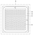
- FIG. 18 is a front view of a heat dissipation cover according to the first embodiment of the present invention.
- FIG. 19 is a rear view of the refrigerator according to the first embodiment of the present invention.
- FIG. 20 is an enlarged view of a portion of the suction grill illustrated in FIG. 19.
- 21 is an enlarged view of a part of a suction grill according to a second embodiment of the present invention.
- FIG. 22 is a partial cross-sectional view of a refrigerator according to a third embodiment of the present invention.
- FIG. 23 is a perspective view of a fixing pin according to a fourth embodiment of the present invention.
- FIG. 24 is a plan view of the fixing pin of FIG.
- FIG. 25 is a perspective view of a heat sink according to a fourth embodiment of the present invention.
- 26 and 27 are views showing the fixing pin is coupled to the heat radiation fins.
- FIG. 28 is a front view of a heat radiation fan according to a fourth embodiment of the present invention.
- FIG. 29 is a view illustrating a heat dissipation fan of FIG. 28 coupled to a fixing pin.
- FIG. 30 is a view showing a part of the fixing guide is removed from the fixing pin.
- FIG. 1 is a perspective view showing the appearance of a refrigerator according to a first embodiment of the present invention
- Figure 2 is an exploded perspective view of a main body, a door and a receiving member of the refrigerator according to the first embodiment of the present invention
- Figure 3 Is an exploded perspective view of the main body of the refrigerator according to the first embodiment of the present invention
- Figure 4 is a perspective view showing the back of the inner case according to the first embodiment of the present invention.
- the side table refrigerator may also function as a side table in addition to the food storage function. Unlike common refrigerators, which are often provided in kitchens, side table refrigerators can be used by the bedroom bed. Therefore, for the convenience of the user, the height of the side table refrigerator is preferably similar to that of the bed, and the height may be lower than that of the general refrigerator and compactly formed.
- the refrigerator according to the first embodiment of the present invention includes a main body 1 having a storage compartment S, a door 2 that opens and closes the storage compartment S, and a storage compartment S. As shown in FIG. It may include a thermoelectric module (3) for cooling.
- the main body 1 may be formed in a box shape.
- the height of the main body 1 is preferably 400mm or more and 700mm or less so that it can be utilized as a side table. That is, the height of the refrigerator may be 400 mm or more and 700 mm or less, but is not limited thereto.
- the upper surface of the main body 1 may be horizontal, and the user may utilize the upper surface of the main body 1 as a side table.
- the main body 1 may be composed of a combination of a plurality of members.
- the main body 1 may include an inner case 10, cabinets 12 and 13 and 14, a cabinet bottom 15, a drain pipe 16, and a tray 17.
- the main body 1 may further include a PCB cover 18 and a heat dissipation cover 8.
- Inner case 10 may be provided with a storage compartment (S).
- the storage chamber S may be formed in the inner case 10.
- One surface of the inner case 10 may be opened, and the opened one surface may be opened and closed by the door 2.
- the front surface of the inner case 10 may be opened.
- thermoelectric module mounting portion 10a may be formed on the rear surface of the inner case 10.
- the thermoelectric module mounting portion 10a may be formed by protruding a part of the rear surface of the inner case 10 to the rear.
- the thermoelectric module mounting portion 10a may be formed closer to the top surface than the bottom surface of the inner case 10.
- the cooling channel S1 (see FIG. 16) may be provided in the thermoelectric module mounting unit 10a.
- the cooling flow path S1 is an internal space of the thermoelectric module mounting portion 10a and may be in communication with the storage chamber S.
- thermoelectric module mounting hole 10b may be formed in the thermoelectric module mounting portion 10a. At least a part of the cooling sink 32 described later of the thermoelectric module 3 may be disposed in the cooling channel S1.
- the cabinets 12, 13 and 14 may constitute an appearance of the refrigerator.
- the cabinets 12, 13, 14 may be arranged to surround the outside of the inner case 10.
- the cabinets 12, 13, 14 may be disposed to be spaced apart from the inner case 10, and a foam material may be inserted between the cabinets 12, 13, 14 and the inner case 10.
- the cabinet 12, 13, 14 may be formed by combining a plurality of members.
- the cabinets 12, 13, 14 may include an outer cabinet 12, a top cover 13, and a back plate 14.
- the outer cabinet 12 may be disposed outside the inner case 10.
- the outer cabinet 12 may be located on the left side, right side, and bottom side of the inner case 10.
- the positional relationship between the outer cabinet 12 and the inner case 10 may vary as necessary.
- the outer cabinet 12 may be disposed to cover the left side, the right side, and the bottom of the inner case 10.
- the outer cabinet 12 may be spaced apart from the inner case 10.
- the outer cabinet 12 may constitute a left side, a right side, and a bottom side of the refrigerator.
- the outer cabinet 12 can be composed of a plurality of members.
- the outer cabinet 12 may include a base that forms the bottom appearance of the refrigerator, a left cover disposed on the upper left side of the base, and a right cover disposed on the upper right side of the base.
- at least one material of the base, the left cover, and the right cover may be different.
- the base may be formed of a synthetic resin material
- the left plate and the right plate may be formed of a metal material such as steel or aluminum.
- the outer cabinet 12 may be composed of one member, and in this case, the outer cabinet 12 may be configured with a lower plate, a left plate, and a right plate that are bent or bent.
- the outer cabinet 12 may be formed of a metal material such as steel or aluminum.
- the top cover 13 may be disposed above the inner case 10.
- the top cover 13 may form an upper surface of the refrigerator.
- the user may utilize the upper surface of the top cover 13 as a side table.
- the top cover 13 may be manufactured in a plate shape, and the top cover 13 may be formed of a wood material. As a result, the appearance of the refrigerator may be more refined. In addition, since the wood material is used for general side table, the user may feel more intuitively the side table use of the refrigerator.
- the top cover 13 may be disposed to cover the top surface of the inner case 10. At least a portion of the top cover 13 may be disposed to be spaced apart from the inner case 10.
- the top surface of the top cover 13 may be disposed to coincide with the top of the outer cabinet 12.
- the left and right widths of the top cover 13 may be the same as the left and right inner widths of the outer cabinet 12.
- the left side and the right side of the top cover 13 may be disposed in contact with the inner surface of the outer cabinet 12.
- the back plate 14 may be disposed vertically.
- the back plate 14 may be disposed at a position behind the top cover 13 while being behind the inner case 10.
- the back plate 14 may be disposed to face the rear surface of the inner case 10 in the front-rear direction.
- the back plate 14 may be disposed to contact the inner case 10.
- the back plate 14 may be disposed close to the thermoelectric module mounting portion 10a of the inner case 10.
- the through plate 14a may be formed in the back plate 14.
- the through hole 14a may be formed at a position corresponding to the thermoelectric module mounting hole 10b of the inner case 10.
- the size of the through hole 14a may be greater than or equal to that of the thermoelectric module mounting hole 10b of the inner case 10.
- the cabinet bottom 15 may be located under the inner case 10.
- the cabinet bottom 15 can support the inner case 10 from below.
- the cabinet bottom 15 may be disposed between the outer bottom surface of the inner case 10 and the inner bottom surface of the outer cabinet 12.
- the cabinet bottom 15 may space the inner case 10 from the inner bottom surface of the outer cabinet 12.
- the cabinet bottom 15 may form a lower heat dissipation flow path 92 (see FIG. 16) together with an inner surface of the outer cabinet 12.
- the drain pipe 16 may communicate with the storage chamber S.
- the drain pipe 16 may be connected to the lower portion of the inner case 10, and may discharge water generated by defrosting in the inner case 10.
- the tray 17 may be located below the drain pipe 16 and may receive water dropped from the drain pipe 16.
- the tray 17 may be disposed between the cabinet bottom 15 and the outer cabinet 12.
- the tray 17 may be located in the lower heat dissipation path 92 (see FIG. 16) to be described later, and water received in the tray 17 may be evaporated by the hot air guided to the lower heat dissipation path 92. Due to the above configuration, there is an advantage that the water in the tray 17 does not have to be emptied frequently.
- the heat dissipation cover 8 may be disposed behind the back plate 14, and may be disposed to face the back plate 14 in the front-rear direction.
- the heat dissipation cover 8 may be disposed to be spaced apart from the back plate 14.
- the heat dissipation cover 8 may be disposed vertically.
- the upper end of the heat dissipation cover 8 may be spaced apart from the top cover 13. That is, the height of the heat dissipation cover 8 may be formed lower than the outer cabinet 12. In this case, the PCB cover 18 to be described later may be exposed to the rear of the main body 1.
- the present invention is not limited thereto, and an upper end of the heat dissipation cover 8 may be disposed to contact the top cover 13.
- the PCB cover 18 may be located in front of the heat dissipation cover 8 and may not be exposed to the rear of the main body 1.
- the heat dissipation cover 8 may include a cover 81 and a suction grill 82 mounted to the cover 81.
- the cover 81 and the suction grille 82 may be integrally formed, or may be formed of separate members.
- At least one outer suction hole 83 may be formed in the heat dissipation cover 8.
- a plurality of outer suction holes 83 may be formed in the suction grill 82.
- the outer suction hole 83 may face the heat dissipation fan 5, and when the heat dissipation fan 5 is driven, external air may flow to the heat dissipation fan 5 through the outer suction hole 83.
- the size and shape of the outer suction hole 83 may vary as necessary.
- the suction grill 82 may be a finger guard that prevents a user's finger from approaching the heat radiating fan 5.
- the outer suction hole 83 is preferably formed to a size such that the user's finger does not enter.
- a cover through hole 81a may be formed in the cover part 81.
- the cover through hole 81a may be formed at a position facing the heat dissipation fan 5.
- the cover through hole 81a may be located between the suction grill 82 and the heat radiating fan 5.
- the air sucked through the outer suction hole 83 may pass through the cover through hole 81a and be sucked into the heat dissipation fan 5.
- the suction grill 82 may cover the cover through hole 81a.
- the suction grill 82 may face the heat radiating fan 5.
- the front surface of the suction grill 82 may face the heat radiating fan 5 in the front-rear direction.
- the suction grill 82 may be disposed to be spaced apart from the heat radiating fan 5.
- the separation distance between the suction grill 82 and the heat radiating fan 5 may be longer than the front maximum elastic deformation length of the suction grill 82. Thus, even if the user presses the suction grille 82 by hand, the suction grille 82 may not touch the heat radiating fan 5.
- the cover portion 81 may have a recessed portion 84 formed to be recessed rearward.
- the recessed portion 84 may be formed by recessing a portion of the cover portion 81 to the rear.
- the cover through hole 81a may be formed in the depression 84, and the suction grill 82 may be mounted in the depression 84.
- the distance between the suction grille 82 and the heat radiating fan 5 may be increased, so that the suction grille may be increased without increasing the length of the refrigerator in front and rear directions.
- the heat dissipation cover 8 may form a rear heat dissipation passage 91 (see FIG. 16) together with the back plate 14.
- the rear heat dissipation flow path 91 may be located between the front surface of the heat dissipation cover 8 and the rear surface of the back plate 14.
- the rear heat dissipation flow path 91 may be located between the front surface of the cover portion 81 and the rear surface of the back plate 14.
- the refrigerator may further include a blocking member 85 that closes the gap 86 between the heat dissipation fan 5 and the heat dissipation cover 8 (see FIG. 17).
- the blocking member 85 may have a square ring shape.
- the blocking member 85 may be formed by combining a plurality of members.
- the blocking member 85 may have a porous material.
- the blocking member may be made of ethylene propylene (EPDM).
- the blocking member 85 having a porous material has excellent sound absorption and absorption performance, vibration and noise generated by the driving of the heat radiating fan 5 can be effectively reduced.
- the blocking member 85 may be disposed to contact the heat dissipation cover 8.
- the blocking member 85 may be disposed to contact the front surface of the heat dissipation cover 8. It is also possible that the blocking member 85 is arranged to contact the inner circumference of the cover through hole 81a.
- the blocking member 85 may be disposed to contact the cover portion 81 and / or the suction grill 82. When the blocking member 85 is in contact with the cover portion 81, the blocking member 85 may be in contact with the recessed portion 84.
- the blocking member 85 may close the gap 86 (see FIG. 17) between the heat dissipation fan 5 and the heat dissipation cover 8. As a result, the air heated in the heat sink 33 of the thermoelectric module 3 can be prevented from flowing to the heat radiating fan 5 by the gap 86 between the heat radiating fan 5 and the heat radiating cover 8. .
- the door 2 can open and close the storage compartment (S).
- the door 2 may be combined with the main body 1, and the coupling manner and number thereof are not limited.
- the door 2 may be a single one-way door or a plurality of two-way doors that can be opened and closed by hinges.
- the case where the door 2 is a drawer-type door slidably connected in the front-rear direction from the main body 1 will be described as an example.
- the door 2 may be coupled to the front surface of the main body 1.
- the door 2 may cover the open front surface of the inner case 10, thereby opening and closing the storage compartment S.
- the door 2 may be formed of a wood material, but is not limited thereto.
- the vertical height of the door 2 may be lower than the height of the outer cabinet 12.
- the lower end of the door 2 may be arranged to be spaced apart from the inner bottom of the outer cabinet 12.
- a heat dissipation passage outlet 90 communicating with the lower heat dissipation passage 92 may be formed.
- the door 2 may be coupled to the main body 1 in a sliding manner.
- the door 2 may be provided with a pair of sliding members 20, and the sliding member 20 may be fastened and slidably coupled to the pair of sliding rails 19 provided in the storage chamber S. As a result, the door 2 may slide back and forth while maintaining a state facing the open front of the inner case 10.
- the sliding rail 19 may be provided on the left inner surface and the right inner surface of the inner case 10.
- the sliding rail 19 may be provided at a position closer to the bottom surface than the upper surface of the inner case 10.
- the user can open the storage compartment S by pulling the door 1 and close the storage compartment S by pushing the door 2.
- the refrigerator may further include at least one accommodating member 6 and 7 disposed in the storage compartment S.
- the kind of the accommodating members 6 and 7 is not limited.
- the receiving members 6 and 7 can be shelves or drawers.
- a description will be given based on the case where the housing members 6 and 7 are drawers.
- Foods may be placed or stored in the receiving members 6 and 7.
- Each housing member 6 and 7 may be configured to be slidable in the front-rear direction. At least one pair of accommodating member rails corresponding to the number of accommodating members 6 and 7 may be provided on the left inner side and the right inner side of the inner case 10, and each accommodating member 6 and 7 may be disposed in the accommodating member. It can be slidably fastened with the member rail.
- the receiving members 6 and 7 may be configured to move together with the door 2.
- the receiving members 6 and 7 may be detachably coupled by the door 2 and the magnet. In this case, when the user pulls the door 2 to open the storage chamber S, the storage members 6 and 7 may be moved forward along the door 2. It is also possible that the receiving members 6 and 7 are configured to be moved independently without moving with the door 2.
- the accommodation members 6 and 7 may be arranged horizontally in the storage chamber S.
- the upper surface of the receiving members 6 and 7 may be opened, and food and beverage may be stored inside the receiving members 6 and 7.
- the accommodating members 6 and 7 may include a first accommodating member 6 and a second accommodating member 7.
- the first storage member 6 may be disposed below the second storage member 7.
- the longitudinal lengths of the first and second receiving members 6 and 7 may be the same or different.
- the vertical heights of the first and second housing members 6 and 7 may be the same or different.
- thermoelectric module 3 may cool the storage chamber (S).
- the thermoelectric module 3 may maintain the temperature of the storage chamber S by utilizing the Peltier effect.
- thermoelectric module 3 may be disposed in front of the heat dissipation cover 8.
- the thermoelectric module 3 may include a thermoelectric element 31 (see FIG. 6), a cooling sink 32 (see FIG. 6), and a heat sink 33 (see FIG. 6).
- the thermoelectric element 31 may include a low temperature portion and a high temperature portion, and the low temperature portion and the high temperature portion may be determined according to a direction of a voltage applied to the thermoelectric element 31. In addition, the temperature difference between the low temperature portion and the high temperature portion may be determined according to the voltage applied to the thermoelectric element 31.
- thermoelectric element 31 may be disposed between the cooling sink 32 and the heat sink 33 and may be in contact with each of the cooling sink 32 and the heat sink 33.
- the low temperature portion of the thermoelectric element 31 may contact the cooling sink 32, and the high temperature portion of the thermoelectric element 31 may contact the heat sink 33.
- thermoelectric module 3 The detailed configuration of the thermoelectric module 3 will be described later in detail.
- the refrigerator may further include a cooling fan 4 circulating air to the cooling sink 32 and the storage room S of the thermoelectric module 3.
- the refrigerator may further include a heat radiating fan 5 for flowing external air to the heat sink 33 of the thermoelectric module 3.
- the cooling fan 4 may be disposed at the front of the thermoelectric module 3, and the heat radiating fan 5 may be disposed at the rear of the thermoelectric module 3.
- the cooling fan 4 may be disposed to face the cooling sink 32 in the front and rear direction, and the heat radiating fan 5 may be disposed to face the heat sink 33 in the front and rear direction.
- the cooling fan 4 may be disposed inside the inner case 10.
- the cooling fan 4 may flow the air of the storage compartment S into the cooling passage S1 (see FIG. 16), and the low-temperature air that is heat-exchanged with the cooling sink 32 disposed in the cooling passage S1 is stored again. Flow to (S) can keep the temperature in the storage chamber (S) low.
- the heat radiating fan 5 may suck the outside air through the outer suction hole 83 formed in the heat radiating cover 8. In more detail, the heat radiating fan 5 may suck external air through the outer suction hole 83 formed in the suction grill 82.
- the air sucked by the heat dissipation fan 5 may exchange heat with the heat sink 33 positioned between the back plate 14 and the heat dissipation cover 8 and heat dissipate the heat sink 33.
- the hot air heat-exchanged with the heat sink 33 is sequentially guided to the rear heat dissipation passage 91 (see FIG. 16) and the lower heat dissipation passage 92 (see FIG. 16), and the heat dissipation passage outlet 90 positioned under the door 2 is provided. Can be taken out.
- the heat radiating fan 5 may be disposed to face the suction grill 82. In addition, the heat radiating fan 5 may be disposed to face the outer suction hole 83.
- FIG. 5 is a perspective view illustrating a thermoelectric module and a heat dissipation fan according to a first embodiment of the present invention
- FIG. 6 is an exploded perspective view of the thermoelectric module and a heat dissipation fan shown in FIG. 5
- FIG. 7 is a thermoelectric shown in FIG. 5.
- Figure 8 is an exploded perspective view of the module and the heat dissipation fan from different directions
- Figure 8 is a cross-sectional view showing a thermoelectric module and the heat dissipation fan according to the first embodiment of the present invention
- FIG. 11 is a plan view for explaining a configuration in which the thermoelectric module and a heat dissipation fan are fixed by a fixing pin.
- 12 is a front view of a thermoelectric module according to a first embodiment of the present invention
- FIG. 13 is a view for explaining a configuration in which the thermoelectric module according to the first embodiment of the present invention is mounted on a thermoelectric module holder
- FIG. 14 is According to the first embodiment of the present invention It is a cut-away perspective view in the case where a thermoelectric module is mounted in the inner case, and the thermoelectric module holder.
- thermoelectric module 3 and the heat radiating fan 5 will be described with reference to FIGS. 5 to 14.
- the thermoelectric module 3 may maintain the temperature of the storage chamber S by utilizing the Peltier effect.
- the thermoelectric module 3 includes a thermoelectric element 31, a cooling sink 32, and a heat sink 33.
- thermoelectric element 31 may be provided with a fuse 35, and when an overvoltage is applied to the thermoelectric element, the fuse 35 may block a voltage applied to the thermoelectric element 31.
- the cooling sink 32 may be a cooling heat exchanger connected to a low temperature portion of the thermoelectric element 31, and may cool the storage compartment S.
- the heat sink 33 may be a heat exchanger connected to a high temperature portion of the thermoelectric element 31, and may radiate heat absorbed by the cooling sink 33.
- the thermoelectric module 3 may be disposed in front of the heat dissipation cover 8.
- the cooling sink 32 may be disposed closer to the inner case 10 than the heat sink 33.
- the cooling sink 32 may be disposed in front of the thermoelectric element 31.
- the cooling sink 32 may be kept at a low temperature in contact with the low temperature portion of the thermoelectric element 31.
- the heat sink 33 may be disposed closer to the heat dissipation cover 8 described later than the cooling sink 32.
- the heat sink 33 may be maintained at a high temperature in contact with the high temperature portion of the thermoelectric element 31.
- the heat sink 33 may be disposed below the control unit 18a to be described later.
- thermoelectric element 31, the cooling sink 32, and the heat sink 33 may be disposed to penetrate the through hole 14a.
- the heat sink 33 may be disposed to penetrate the through hole 14a.
- the thermoelectric element 31 and the cooling sink 32 may be located in front of the through hole 14a, and part of the heat sink 33 may be located behind the through hole 14a.
- the cooling sink 32 may include a cooling plate 32a and a cooling fin 32b.
- the cooling plate 32a may be disposed to contact the thermoelectric element 31. A part of the cooling plate 32a may be inserted into the element accommodating hole 37a formed in the heat insulating member 37 to contact the thermoelectric element 31.
- the cooling plate 32a may be positioned between the cooling fin 32b and the thermoelectric element 31, and the cooling plate 32a may be in contact with the low temperature portion of the thermoelectric element 31 to transfer the heat of the cooling fin 32b to the thermoelectric element ( Can be delivered to the low temperature portion of 31).
- the cooling plate 32a may be formed of a material having high thermal conductivity.
- the cooling plate 32a may be located in the thermoelectric module mounting hole 10b of the inner case 10.
- the cooling sink 32 may be disposed to block the thermoelectric module mounting hole 10b of the inner case 10.
- the cooling plate 32a may block the thermoelectric module mounting hole 10b of the inner case 10.
- the cooling fin 32b may be disposed to contact the cooling plate 32a.
- the cooling fin 32b may protrude from one surface of the cooling plate 32a.
- the cooling fin 32b may be located in front of the cooling plate 32a. At least a portion of the cooling fin 32b may be located in the cooling channel S1 in the thermoelectric module mounting unit 10a, and may cool the air by exchanging heat with the air in the cooling channel S1.
- the cooling fin 32b may have a plurality of fins to increase the heat exchange area with air.
- the cooling fins 32b may be arranged to guide the air in the vertical direction.
- Each of the plurality of fins constituting the cooling fin 32b may be configured as a vertical plate having a left side and a right side and arranged in a vertical direction.
- the cooling fin 32b may be disposed to be positioned between the fan 42 of the cooling fan 4 and the thermoelectric element 31, and the air blown from the fan 42 of the cooling fan 4 may be upper discharge holes. 45 and the lower discharge hole 46 can be guided. The air blown by the fan 42 of the cooling fan 4 may be guided to the cooling fin 32b and distributed up and down.
- the heat sink 33 may include a heat dissipation plate 33d, a heat dissipation pipe 33b, and a heat dissipation fin 33c.
- the heat sink 33 may further include an element contact plate 33a coupled to the heat dissipation plate 33d.
- the element contact plate 33a may be disposed to contact the thermoelectric element 31. A portion of the element contact plate 33a may be inserted into the element accommodating hole 37a formed in the heat insulating member 37 to contact the thermoelectric element 31.
- the heat dissipation plate 33d may be in contact with the heat dissipation fin 33c, and a portion of the heat dissipation pipe 33b may be positioned between the heat dissipation plate 33d and the element contact plate 33a.
- the element contact plate 33a may be in contact with the high temperature portion of the thermoelectric element 31 to conduct heat to the heat dissipation pipe 33b, and the heat dissipation pipe may conduct heat to the heat dissipation plate 33d and the heat dissipation fin 33c.
- the element contact plate 33a and the heat dissipation plate 33d may be formed of a material having high thermal conductivity.
- At least one of the heat dissipation plate 33d and the heat dissipation fin 33c may be disposed in the through hole 14a of the back plate 14.
- the heat dissipation pipe 33b may be a heat pipe in which a heat transfer fluid is embedded. A portion of the heat dissipation pipe 33b may be disposed through the heat dissipation fin 33c.
- the portion of the heat dissipation pipe 33b in contact with the heat dissipation plate 33d may evaporate, and the portion of the heat dissipation pipe 33b in contact with the heat dissipation fin 33c may condense.
- the heat transfer fluid circulates in the heat dissipation pipe 33b by the density difference and / or gravity, and can conduct heat from the element contact plate 33a and the heat dissipation plate 33d to the heat dissipation fin 33c.
- the heat dissipation fin 33c may be in contact with at least one of the heat dissipation plate 33d and the heat dissipation pipe 33b, spaced apart from the heat dissipation plate 33d, and connected to the heat dissipation plate 33a through the heat dissipation pipe 33b. It is also possible. When the heat dissipation fin 33c is disposed in contact with the heat dissipation plate 33d, the heat dissipation pipe 33b may be omitted.
- the heat dissipation fin 33c may include a plurality of fins disposed perpendicular to the heat dissipation pipe 33b.
- the heat dissipation fin 33c may guide the air blown from the heat dissipation fan 5, and the air guide direction of the heat dissipation fin 33c may be different from the air guide direction of the cooling fin 32b.
- the heat radiation fin 33c may guide the air in the left and right directions.
- the heat dissipation fin 33c may be formed to guide air in a horizontal direction (particularly, the left and right directions in the front-rear direction and the left-right direction), and each of the fins constituting the heat dissipation fin 33c has an upper surface and a lower surface. It is preferable that it is comprised with the horizontal board arrange
- the plurality of heat dissipation plates 33c may be stacked in the vertical direction.
- the heat dissipation fin 33c When the heat dissipation fin 33c is formed long in the vertical direction, there may be a lot of air flowing toward the controller 18a of the air guided by the heat dissipation fin 33c. On the other hand, when the heat radiation fin 33c is formed long in the horizontal direction as described above, the air flowing toward the control unit 18a of the air guided by the heat radiation fin 33c can be minimized.
- the heat dissipation plate 33d may be located between the heat dissipation fin 33c and the thermoelectric element 31, and the heat dissipation fin 33c may be positioned behind the heat dissipation plate 33d.
- the heat dissipation fin 33c may be located at the rear of the back plate 14.
- the heat dissipation fin 33c may be positioned between the back plate 14 and the heat dissipation cover 8, and may be heat-dissipated by heat exchange with external air sucked by the heat dissipation fan 5.
- thermoelectric module 3 may further include a module frame 34 and a heat insulating member 37.
- the module frame 34 may be box shaped.
- the module frame 34 may have a space in which the heat insulating member 37 and the thermoelectric element 31 are accommodated.
- the module frame 34 and the heat insulating member 37 may protect the thermoelectric element 31.
- the module frame 34 may be formed of a material capable of minimizing heat loss due to heat conduction.
- the module frame 34 may have a nonmetallic material such as plastic.
- the module frame 34 may prevent heat of the heat sink 33 from being conducted to the cooling sink 32.
- a gasket 36 may be provided on the front surface of the module frame 34.
- the gasket 36 may have an elastic material such as rubber or the like.
- the gasket 36 may be formed in a rectangular ring shape, but is not limited thereto.
- the gasket 36 may be a sealing member.
- the gasket 36 may be disposed to be in contact with the rear surface of the thermoelectric module mounting portion 10a and / or the circumference of the thermoelectric module mounting hole 10b.
- the gasket 36 may be disposed between the module frame 34 and the thermoelectric module mounting portion 10a and may be compressed in the front-rear direction.
- the gasket 36 may prevent the cool air of the cooling flow path S1 in the thermoelectric module mounting portion 10a from leaking into a gap between the thermoelectric module mounting hole 11b and the cooling sink 32.
- the module frame 34 may be provided with a fastening part 34a.
- the fastening part 34a may be formed to extend outward from at least a portion of the circumference of the module frame 34.
- the fastening part 34a may be formed to extend outwardly from the left and right surfaces of the module frame 34, respectively.
- the fastening portion 34a may include a boss 34b.
- a thread may be formed inside the boss 34b, and a fastening member such as a bolt may be fastened.
- the fastening member may be coupled to the boss 34b of the fastening part 34a of the module frame 34 by passing through the fastening hole 10c formed in the inner case 10 in the inner case 10.
- thermoelectric module 3 and the inner case 10 may be firmly fastened, and cold air in the inner case 10 may be prevented from leaking.
- the heat insulating member 37 may be disposed to surround the outer circumference of the thermoelectric element 31.
- the heat insulating member 37 may be disposed to surround the upper surface, the left surface, the lower surface, and the right surface of the thermoelectric element 31.
- the thermoelectric element 31 may be located in the heat insulating member 37.
- the heat insulating member 37 may be provided with an element accommodating hole 37a open in the front-rear direction, and the thermoelectric element 31 may be located in the thermoelectric element accommodating hole 37a.
- the thickness in the front-rear direction of the heat insulating member 37 may be thicker than the thickness of the thermoelectric element 31.
- the heat insulating member 37 may prevent the heat from being conducted around the thermoelectric element 31 in the thermoelectric element 31, thereby increasing the efficiency of the thermoelectric element 31. That is, the circumference of the thermoelectric element 31 may be surrounded by the heat insulating member 37, and it is possible to minimize the heat transferred from the heat sink 33 to the cooling sink 32.
- the heat insulating member 37 may be disposed inside the module frame 34 together with the thermoelectric element 31, and may be protected by the module frame 34.
- the module frame 34 may be disposed to surround the outer circumference of the heat insulating member 37.
- the refrigerator may further include a thermoelectric module holder 11 (see FIG. 3) for fixing the thermoelectric module 3 to the inner case 10 and / or the back plate 14.
- thermoelectric module holder 11 may couple the thermoelectric module 3 with the inner case 10 and / or the back plate 14.
- thermoelectric module holder 11 may be coupled to the thermoelectric module mounting portion 10a and / or the back plate 14 of the inner case 10 by a fastening member (not shown) such as a screw.
- thermoelectric module holder 11 may block the through hole 14a of the back plate 14 together with the thermoelectric module 3.
- the thermoelectric module holder 11 may be provided with a hollow portion 11a.
- the hollow part 11a may be formed by extending a portion of the thermoelectric module holder 11 forward.
- the module frame 34 may be inserted into and inserted into the hollow part 11a, and the hollow part 11a may wrap around the module frame 34.
- the front part of the thermoelectric module 3 may be located in front of the through hole 14a of the back plate 14, and the rear part of the thermoelectric module 3 may be located behind the through hole 14a of the back plate 14. .
- the thermoelectric module 3 may further include a sensor 39.
- the sensor 39 may be disposed in the cooling sink 32.
- the sensor 39 may be a temperature sensor or a defrost sensor.
- the heat radiating fan 5 may be disposed at the rear of the thermoelectric module 3.
- the heat dissipation fan 5 may be disposed to face the heat sink 33 at the rear of the heat sink 33, and blow external air to the heat sink 33.
- the heat radiating fan 5 may include a fan 52 and a shroud 51 disposed around the fan 52.
- the fan 52 of the heat dissipation fan 5 may be an axial fan.
- the heat radiating fan 5 may be disposed to be spaced apart from the heat sink 33. Thereby, the flow resistance of the air blown by the heat radiating fan 5 can be minimized, and the heat exchange efficiency in the heat sink 33 can be increased.
- At least one fixing pin 53 may be provided at the heat radiating fan 5.
- the fixing pin 53 may be in contact with the heat sink 33, and may be fixed to the heat sink 33 while separating the heat radiating fan 5 from the heat sink 33.
- the fixing pin 53 may be formed of a material having low thermal conductivity such as rubber or silicon.
- the fixing pin 53 may be formed of a material capable of absorbing vibration. In order for the fixing pin 53 to absorb vibrations, the fixing pin 53 may be deformable in appearance.
- the fixing pin 53 may include a head portion 53a, a first fixing portion 53e, a body portion 53b, and a second fixing portion 53c.
- the head portion 53a may be in contact with the heat sink 33.
- the head portion 53a may be in contact with the heat dissipation pipe 33b and / or the heat dissipation fin 33c of the heat sink 33.
- the groove 33d may be formed in a portion adjacent to a portion where the heat pipe 33b is disposed through and through the heat dissipation fin 33c.
- the groove 33d formed in the heat dissipation fin 33c may be formed long in the vertical direction.
- the head portion 53a may be seated on the pin without the groove located directly below the fin on which the groove 33d is formed.
- the head portion 53a of the fixing fin 53 may be inserted into and fixed to the groove 33d of the heat dissipation fin 33c.
- the inlet portion of the groove 33d may be formed to have a smaller width than the other portion.
- the head portion 53a may be fitted in the groove 33d in the vertical direction. Therefore, the head portion 53a can be prevented from falling out of the groove 33d in the horizontal direction while the head is fitted in the groove 33d.
- the first fixing part 53e may be formed at one side of the head part 53a.
- the body portion 53b may extend in the horizontal direction from the first fixing portion 53e.
- the length of the body portion 53b may be longer than the length of the first fixing portion 53e, and the diameter of the body portion 53b may be smaller than the diameter of the first fixing portion 53e.
- the second fixing part 53c may be located opposite to the first fixing part 53e in the body part 53b.
- the length of the body portion 53b may be longer than the length of the second fixing portion 53c, and the diameter of the body portion 53b may be smaller than the diameter of the second fixing portion 53c.
- the body portion 53b may be coupled to the heat radiating fan 5.
- the body portion 53b may be coupled to the fixing pin through hole 51a formed in the shroud 51.
- the diameter of the body portion 53b may be the same as or smaller than the fixing pin through hole 51a.
- the diameters of the first fixing part 53e and the second fixing part 53c are larger than the diameter of the fixing pin through hole 51a.
- the fixing pin 53 is formed of a deformable material, so that the second fixing part 53c is formed of the fixing pin through hole 51a. Can penetrate).
- the diameter of the second fixing part 53c may decrease as the second fixing part 53c penetrates the fixing pin through hole 51a so that at least a part of the second fixing part 53c moves away from the body part 53b.
- the second fixing part 53c may be formed in a truncated cone or cone shape.
- the longitudinal length of the body portion 53b may be the same as the longitudinal thickness of the heat radiating fan 5.
- the first fixing part 53e contacts the front surface of the heat radiating fan 5
- the second fixing part 53c is in contact with the rear surface of the heat radiating fan 5.
- the heat dissipation fan 5 is spaced apart from the heat sink 33 by the length of the first fixing part 53e.
- the fixing pin 53 may further include a fixing guide 53d.
- the fixing guide 53d may extend from the second fixing portion 53c.
- the diameter of the fixing guide 53d may be smaller than the second fixing part 53c.
- the heat radiating fan 5 can be moved toward the heat radiating fin 33c in a state where the fixing guide 53d is gripped. There is an advantage that the coupling of the heat radiating fan (5) is easy.
- a portion of the fixing guide 53d may be removed in a state in which the heat dissipation fin 5 is fixed to the fixing fin 53.
- FIG. 15 is a perspective view illustrating a cooling fan according to a first embodiment of the present invention.
- the cooling fan 4 may be disposed in front of the thermoelectric module 3, and may be disposed to face the cooling sink 32.
- the cooling fan 4 may circulate air to the cooling passage S1 and the storage chamber S. Forced convection may be performed between the cooling passage S1 and the storage chamber S by the cooling fan 4.
- the cooling fan 4 may flow the air of the storage compartment S into the cooling passage S1, and the low-temperature air that is heat-exchanged with the cooling sink 32 disposed in the cooling passage S1 is returned to the storage compartment S. It can be flowed to keep the temperature in the storage chamber S low.
- the cooling fan 4 may include a fan cover 41 and a fan 42.
- the fan cover 41 may be disposed in the inner case 10.
- the fan cover 41 may be disposed vertically.
- the fan cover 41 may partition the storage compartment S and the cooling passage S1.
- the storage compartment S may be located at the front of the fan cover 41, and the cooling passage S1 may be located at the rear of the fan cover 41.
- An inner suction hole 44 and an inner discharge hole 45 and 46 may be formed in the fan cover 41.
- the number, size, and shape of the inner suction hole 44 and the inner discharge hole 45 and 46 may vary as necessary.
- the inner discharge holes 45 and 46 may include an upper discharge hole 45 and a lower discharge hole 46.
- the upper discharge hole 45 may be formed above the inner suction hole 44, and the lower discharge hole 46 may be formed below the inner suction hole 44. This configuration has the advantage that the temperature distribution in the storage chamber S can be made uniform.
- the area of the upper discharge hole 45 and the area of the lower discharge hole 46 may be the same.
- the distance G1 between the upper end 46a of the lower discharge hole 46 and the lower end 44b of the inner suction hole 44 is the upper end 45b of the upper discharge hole 45 and the upper end of the inner suction hole 44. It may be formed closer than the distance (G2) between (44a). That is, the inner suction hole 44 may be formed at a position closer to the lower discharge hole 46 than the upper discharge hole 45.
- the area of the inner suction hole 44 may vary depending on the size of the fan 41, and the areas of the inner discharge holes 45 and 46 may be formed at a predetermined ratio with respect to the area of the inner suction hole 44.
- the area of the inner discharge holes 45 and 46 may be larger than the area of the inner suction hole 44.
- the area of the inner discharge holes 45 and 46 may be 1.3 times or more and 1.5 times or less of the area of the inner suction holes 44.
- the fan cover 41 may be provided with a fan housing 47.
- the fan accommodating part 47 may be formed by protruding a portion of the front surface of the fan cover 41 forward, and a fan accommodating space may be formed in the fan accommodating part 47.
- At least a part of the fan 42 may be disposed in a fan accommodation space formed in the fan accommodation portion 47.
- the inner suction hole 44 may be formed in the fan accommodating portion 47.
- the fan 42 may be disposed in the cooling channel S1 and may be disposed behind the fan cover 41.
- the fan cover 41 may cover the fan 42 from the front.
- the fan 42 may be disposed to face the cooling sink 32.
- the fan 42 may be disposed between the inner suction hole 44 and the cooling sink 32.
- the fan 42 may be disposed to face the inner suction hole 44.
- air in the storage compartment S may be sucked into the cooling flow path S1 through the inner suction hole 44 to be heat-exchanged with the cooling sink 32 of the thermoelectric module 3 to be cooled.
- the cooled air may be discharged to the storage chamber S through the inner discharge holes 45 and 46, whereby the temperature of the storage chamber S may be maintained at a low temperature.
- a part of the air cooled in the cooling sink 32 may be guided upward to be discharged to the storage chamber S through the upper discharge hole 45, and the other part may be guided downward to guide the lower discharge hole 46. May be discharged into the storage chamber (S).
- FIG. 16 is a cross-sectional view of a refrigerator according to a first embodiment of the present invention
- FIG. 17 is an enlarged cross-sectional view of a thermoelectric module periphery of the refrigerator shown in FIG. 16
- FIG. 18 is a heat dissipation cover according to a first embodiment of the present invention. Front view.
- each of the inner suction hole 44 and the lower discharge hole 46 may face between the first storage member 6 and the second storage member 7.
- at least a portion of the upper discharge hole 45 may face between the upper surface of the storage chamber 10 and the second storage member 7.
- the lower end 46b of the lower discharge hole 46 may be positioned above the rear side of the first storage member 6. In more detail, the lower end 46b of the lower discharge hole 46 may be positioned behind the upper end 63 of the rear side of the first accommodating member 6.
- the rear surface 61 of the first storage member 6 may be disposed to face the lower portion of the lower discharge hole 46 with respect to the horizontal direction, and the lower discharge hole 46 may be disposed with the first storage member (with respect to the horizontal direction). It may not overlap with 6). That is, the first storage member 6 may be disposed so as not to cover the lower discharge hole 46 in the horizontal direction.
- the flow of low-temperature air discharged into the lower discharge hole 46 may not be disturbed by the first storage member 6, so that air circulation in the storage chamber S may be smoothly performed.
- the food stored in the first storage member 6 can be kept at a low temperature.
- the lower discharge hole 46 and the first storage member 6 may be spaced apart from each other.
- the lower end 46b of the lower discharge hole 46 and the first storage member 6 are spaced apart by the first horizontal distance D1 in the horizontal direction, and at the same time, the first vertical distance H1 in the vertical direction. Can be spaced apart).
- the first horizontal separation distance D1 may mean a horizontal distance between the extension line extending vertically upward from the rear surface 61 of the first storage member 6 and the lower discharge hole 46.
- the first vertical separation distance H1 may mean a vertical distance between an extension line extending horizontally forward from the lower end 46b of the lower discharge hole 46 and the upper end 60 of the first storage member 6. have.
- the first horizontal separation distance D1 may mean a separation distance between the rear surface of the storage chamber S and the first storage member.
- the rear surface of the storage chamber S may be the front surface of the fan cover 41.
- the first vertical separation distance H1 may be a height difference between the lower end 46b of the lower discharge hole 46 and the upper end 60 of the first storage member 6.
- a portion of the upper discharge hole 45 may overlap the second storage member 7 in the horizontal direction.
- the upper portion of the upper discharge hole 45 may face between the upper end 70 of the second storage member 7 and the upper surface of the storage S, and the lower portion of the upper discharge hole 45 may The rear surface 71 of the second storage member 7 can be faced.
- the upper end 45a of the upper discharge hole 45 may be positioned behind the upper end 73 of the rear side of the second storage member 7.
- the height of the storage compartment S may be lower than that of the case where the upper discharge hole 45 does not overlap with the second storage member 7 in the horizontal direction, and the refrigerator may be compactly formed.
- the inner suction hole 44 in the fan cover 41 may be formed closer to the lower discharge hole 46 than the upper discharge hole 45.
- the height of the storage chamber S for satisfying the positional relationship between the storage members 6 and 7, the inner suction hole 44, and the inner discharge hole 45 and 46 described above may be further lowered.
- At least a part of the rear surface 71 of the second storage member 7 may be formed to be inclined upward toward the front.
- a portion facing the upper discharge hole 45 of the rear surface 71 of the second storage member 7 may be a gradient surface 72 formed to be inclined upward.
- a part of the lower side of the upper discharge hole 45 may face the gradient surface 72.
- the gradient surface 72 may guide the low temperature air discharged to the upper discharge hole 45 to the upper side of the second storage member 7. As a result, the food stored in the second storage member 7 can be kept at a low temperature.
- the upper discharge hole 45 and the second storage member 7 may be spaced apart from each other.
- the upper end 45a of the upper discharge hole 45 and the second storage member 7 are spaced apart by the second horizontal separation distance D2 in the horizontal direction, and at the same time, the second vertical separation distance H2 in the vertical direction. Can be spaced apart).
- the second horizontal separation distance D2 may mean a horizontal distance between the rear surface 71 of the second storage member 7 and the upper discharge hole 45.
- the second vertical separation distance H2 may mean a vertical distance between the extension line extending horizontally forward from the upper end 45a of the upper discharge hole 45 and the upper end 70 of the second storage member 7. have.
- the second horizontal separation distance D2 may mean a separation distance between the rear surface of the storage chamber S and the second storage member 7.
- the rear surface of the storage chamber S may be the front surface of the fan cover 41.
- the second vertical separation distance H2 may be a height difference between the upper end 45a of the upper discharge hole 45 and the upper end 60 of the second storage member 7.
- the second horizontal separation distance D2 between the rear surface 71 of the second storage member 7 and the upper discharge hole 45 is the rear surface 61 and the lower discharge hole 46 of the first storage member 6. It may be longer than the first horizontal separation distance (D1) between. This is because, unlike the first storage member 6, the second storage member 7 faces a part of the upper discharge hole 45 in the horizontal direction, so an additional separation distance for air circulation in the storage chamber S is required. Because. Therefore, the longitudinal length of the first storage member 6 may be longer than the longitudinal length of the second storage member 7.
- the inner suction hole 44 may face between the first storage member 6 and the second storage member 7.
- the inner suction hole 44 may not overlap the second storage member 7 in the horizontal direction. As a result, the air flow to the inner suction hole 44 is smooth, and the temperature of the storage compartment S is lowered, thereby improving the refrigerating performance of the refrigerator.
- the vertical height of the second storage member 7 may be lower than the vertical height F1 of the first storage member. Due to this configuration, food having a high height such as a bottle may be accommodated in the first storage member 6, and food having a relatively low height may be accommodated in the second storage member 7.
- the heat dissipation passages 91 and 92 and the cooling passage S1 may be formed in the refrigerator.
- the cooling sink 32 may be disposed in the cooling passage S1, and the heat sink 33 may be disposed in the heat dissipation passages 91 and 92.
- the cooling passage S1 may communicate with the storage chamber S, and the heat dissipation passages 91 and 92 may communicate with the outside of the main body 1.
- the air in the storage compartment S may be guided to the cooling flow path S1 by the driving of the cooling fan 4, and may be cooled by heat exchange with the cooling sink 32.
- the cooling flow path S1 may be located inside the inner case 10.
- the cooling passage S1 may be located inside the thermoelectric module mounting portion 10a.
- the cooling flow path S1 may be formed by the rear surface of the fan cover 41 and the inner surface of the thermoelectric module mounting portion 10a.
- the cooling flow path S1 may be in communication with the inner suction hole 44 and the inner discharge hole 45, 46.
- the cooling sink 32 may be disposed to face the fan 42.
- the cooling passage S1 may guide the air sucked into the inner suction hole 44 to the inner discharge holes 45 and 46.
- the outside air may be guided to the heat dissipation flow paths 91 and 92 by driving the heat dissipation fan 5, and may be heated and heat exchanged with the heat sink 33.
- the heat dissipation paths 91 and 92 may be located outside the inner case 10.
- the heat dissipation passages 91 and 92 may include a rear heat dissipation passage 91 positioned behind the inner case 10 and a lower heat dissipation passage 92 positioned below the inner case 10.
- the rear heat dissipation flow path 91 may be located between the back plate 14 and the heat dissipation cover 8.
- the rear heat dissipation flow path 91 may be formed by the rear surface of the back plate 14 and the inner surface of the heat dissipation cover 8.
- the heat sink 33 may be disposed in the rear heat dissipation passage 91.
- the heat sink 33 may be disposed to face the heat dissipation fan 5.
- At least a part of the rear heat dissipation flow path 91 may be a machine room.
- the rear heat dissipation passage 91 may communicate with the outer suction hole 83.
- the rear heat dissipation flow path 91 may guide the air sucked into the outer suction hole 83 by the heat dissipation fan 5 to the lower heat dissipation flow path 92.
- the lower heat dissipation flow path 92 may be located between the cabinet bottom 15 and the outer cabinet 12.
- the lower heat dissipation flow path 92 may communicate with the rear heat dissipation flow path 91.
- the lower heat dissipation flow path 92 may guide the air flowed from the rear heat dissipation flow path 91 to the heat dissipation flow path outlet 90 under the door 2.
- the PCB cover 18 may cover the controller 18a.
- the controller 18a may include an electronic component such as a PCB substrate.
- the controller 18a may receive and store measured values of each sensor provided in the refrigerator.
- the controller 18a may control the thermoelectric module 3, the cooling fan 4, and the heat radiating fan 5.
- the controller 18a may further control additional components as necessary.
- the control unit 18a may be located above the heat sink 33 and / or the heat dissipation fan 5, and the barrier 18b may be disposed between the heat sink 33 and / or the heat dissipation fan 5 and the control unit 18a. It may be provided. That is, the barrier 18b may be located below the control unit 18a. The barrier 18b can prevent the control unit 18a from overheating by the heat emitted to the heat sink 33. The barrier 18b may also prevent the air heated in the heat sink 33 from flowing to the controller 18a.
- the barrier 18b may be mounted to the heat dissipation cover 8 and / or the back plate 14. Alternatively, the barrier 18b may be mounted on the PCB cover 18 or integrally formed with the PCB cover 18.
- the PCB cover 18 may be disposed above or in front of the heat dissipation cover 8.
- the PCB cover 18 may cover the rear and / or the upper side of the controller 18a.
- the PCB cover 18 may be disposed under the top cover 13 and may be disposed behind the inner case 10. In addition, the PCB cover 18 may be located above the heat sink 33 and / or the heat radiating fan 5 of the thermoelectric module 3 to be described later.
- the PCB cover 18 may cover the rear of the controller 18a.
- the controller 18a can be prevented from being exposed to the rear of the main body 1.
- the blocking member 85 may close the gap 86 between the heat dissipation fan 5 and the heat dissipation cover 8.
- the blocking member 85 may close the gap 86 between the shroud 51 of the heat dissipation fan 5 and the heat dissipation cover 8.
- the air sucked into the heat dissipation fan 5 through the outer suction hole 83 is a heat sink ( 33, which may be heated in the heat sink 33, and a part of the air heated in the heat sink 33 flows into the gap 86 between the shroud 51 and the heat dissipation cover 8 to dissipate the heat dissipation fan. Re-absorption to (5) may cause flow disturbances.
- Such disturbances can generate noise in low frequency region tones, and already heated air can be blown back to the heat sink 33 to reduce the heat dissipation efficiency of the heat sink 33.
- the blocking member 85 is a recirculation in which air heated in the heat sink 33 flows into the gap 86 between the heat radiating fan 5 and the heat radiating cover 8 and is sucked into the heat radiating fan 5. The phenomenon can be prevented. As a result, noise generated by the flow disturbance can be reduced, and the heat dissipation efficiency of the heat sink 33 can be increased.
- the blocking member 85 may have a porous material.
- the blocking member 85 can effectively reduce the vibration and noise generated by the drive itself of the heat radiating fan (5).
- the blocking member 85 may be disposed to contact each of the heat dissipation fan 5 and the heat dissipation cover 8.
- the blocking member 85 may be disposed to surround the outer circumference of the heat dissipation fan 5.
- the blocking member 85 may be arranged to surround the outer circumference of the shroud 51.
- the blocking member 85 may be in contact with the shroud 51.
- the blocking member 85 may be disposed to contact the heat dissipation cover 8, and may be disposed to contact the front surface of the heat dissipation cover 8.
- the blocking member 85 may be disposed to contact the cover portion 81 and / or the suction grill 82. When the blocking member 85 is in contact with the cover portion 81, the blocking member 85 may be in contact with the recessed portion 84.
- the front and rear length L of the blocking member 85 may be longer than the thickness T.
- the front and rear length L of the blocking member 85 may be 15 mm or more and 20 mm or less, and the thickness T of the blocking member 85 may be 5 mm or more and 10 mm or less.
- FIG. 19 is a rear view of the refrigerator according to the first embodiment of the present invention
- FIG. 20 is an enlarged view of a part of the suction grille shown in FIG. 19.
- the outer suction hole 83 formed in the heat dissipation cover 8 may be formed in a plurality of perforated structures.
- a plurality of outer suction holes 83 may be formed in the suction grill 82.
- the outer suction hole 83 may be formed in a circular shape.
- Table 1 is a table measuring the noise of the refrigerator according to an embodiment.
- the unit of noise shown in Table 1 is dBA.
- the measurement noise is measured at a position 1m away from the refrigerator and at a position 1m away from the rear, respectively.
- the cooling fan 4 and the heat radiating fan 5 conditions the cooling fan 4 is driven at 851 rpm and the heat radiating fan 5 is 1807 rpm at low speed, and the cooling fan 4 is 922 rpm at medium speed.
- the heat radiating fan 5 is driven at 1903 rpm, the cooling fan 4 is driven at 947 rpm, and the heat radiating fan 5 is driven at 2001 rpm under high speed conditions.
- the front and rear length L of the blocking member 85 is 20 mm, and the thickness T of the blocking member 85 is 10 mm.
- the refrigerator may have the least noise when the suction grill 82 is not included.
- the suction grill 82 is preferably mounted for the user's safety. Even when the suction grill 82 is mounted, it is preferable that the noise is not increased sharply than when the suction grill 82 is not included.
- the measurement noise is changed by varying the diameter (D) of the outer suction hole (83) formed in the suction grill 82 and the distance (C) between the outer suction hole (83).
- the diameter (D) of the outer suction hole (83) is 7mm or 8mm
- the distance (C) between the outer suction holes (83) is 1mm or 1.5mm
- the noise is not significantly different.
- the diameter D of the outer suction hole 83 may be 7 mm or more and 8 mm or less.
- the distance C between the pair of outer suction holes 83 adjacent to each other among the plurality of outer suction holes 83 may be 1 mm or more and 1.5 mm or less.
- the distance P between the centers of the pair of outer suction holes 83 adjacent to each other among the plurality of outer suction holes 83 may be 7 mm or more and 10 mm or less.
- the diameter D of the outer suction hole 83 is 8 mm, and the distance C between the pair of outer suction holes 83 adjacent to each other may be 1 mm.
- 21 is an enlarged view of a part of a suction grill according to a second embodiment of the present invention.
- the refrigerator according to the present exemplary embodiment is the same as the refrigerator according to the first exemplary embodiment described above except for the suction grille 82, the overlapping description will be omitted and the differences will be mainly described.
- the suction grill 82 may be a mesh composed of a plurality of wires 87.
- the suction grill 82 may include a square outer suction hole 83 formed between each wire 87.
- the wire 87 may include a first wire 87a and a second wire 87b.
- the first wire 87a and the second wire 87b may be arranged to cross each other.
- the outer suction hole 83 may be formed by a pair of first wires 87a adjacent to each other and a pair of second wires 87b adjacent to each other.
- the first wire 87a and the second wire 87b may be orthogonal to each other, and the outer suction hole 83 may have a square shape.
- Table 2 is a table measuring the noise of the refrigerator according to the second embodiment.
- the unit of noise shown in Table 2 is dBA.
- the measurement noise is measured at a position 1m away from the refrigerator and at a position 1m away from the rear, respectively.
- the cooling fan 4 and the heat radiating fan 5 conditions the cooling fan 4 is driven at 851 rpm and the heat radiating fan 5 is 1807 rpm at low speed, and the cooling fan 4 is 922 rpm at medium speed.
- the heat radiating fan 5 is driven at 1903 rpm, the cooling fan 4 is driven at 947 rpm, and the heat radiating fan 5 is driven at 2001 rpm under high speed conditions.
- the longitudinal direction L of the blocking member 85 is 20 mm, and the thickness T of the blocking member 85 is 10 mm.
- sixteen outer suction holes 83 formed of four rows and four columns are formed in an imaginary quadrangle having a horizontal side and a vertical side having a unit length A of 1 inch each.
- the measurement noise is changed by varying the thickness (B) of the wire 87 constituting the suction grill (82).
- the thickness (B) of the wire 87 is 1mm or 1.6mm, it can be seen that the measured noise is not significantly different than when the suction grill 82 is not included.
- the thickness B of the wire 87 may be 1 mm or more and 1.6 mm or less.
- the suction grill 82 may have 16 outer suction holes 83 formed of four rows and four columns per square inch.
- FIG. 22 is a partial cross-sectional view of a refrigerator according to a third embodiment of the present invention.
- the refrigerator according to the present exemplary embodiment is the same as the refrigerator according to the exemplary embodiment described above except for the blocking member 85, the redundant description will be omitted and the following description will focus on differences.
- the blocking member 85 may be disposed between the heat dissipation cover 8 and the heat dissipation fan 5.
- the blocking member 85 may be disposed between the shroud 51 and the heat dissipation cover 8 of the heat dissipation fan 5.
- the blocking member 85 may be disposed to contact each of the heat dissipation fan 5 and the heat dissipation cover 8.
- the blocking member 85 may be disposed to contact the rear surface of the shroud 51, and may be disposed to contact the front surface of the heat dissipation cover 8.
- the blocking member 85 is disposed between the heat dissipation fan 5 and the heat dissipation cover 8, the gap 86 between the heat dissipation fan 5 and the heat dissipation cover 8 is more directly blocked. Can be.
- the blocking member 85 may be compressed in the front-rear direction by each of the heat dissipation fan 5 and the heat dissipation cover 8, the gap between the blocking member 85 and the heat dissipation fan 5, the blocking member 85, and The gaps between the heat dissipation covers 8 can each be effectively sealed. As a result, the blocking member 85 can more effectively prevent the flow disturbance.
- the blocking member 85 has a porous material, vibration caused by the driving of the heat radiating fan 5 may be sucked by the blocking member 85 to prevent the vibration of the heat radiating cover 8.
- FIG. 23 is a perspective view of a fixing pin according to a fourth embodiment of the present invention
- FIG. 24 is a plan view of the fixing pin of FIG. 23.
- the fixing pin of the present embodiment has the same function as the fixing pin mentioned in the first embodiment, but there is a difference in structure, so only the parts that are different from the first embodiment will be described below.
- the fixing pin 100 of the present exemplary embodiment may include a head part 110, a first fixing part 130, a body part 140, and a second fixing part 150.
- the head unit 110 may be coupled to the heat sink 33.
- the head portion 110 has a first portion 111 having a first diameter and a second portion 112 extending downward from the first portion 111 and having a second diameter smaller than the first diameter. It may include.
- the vertical length of the second portion 112 may be longer than the vertical length of the first portion 111.
- the fixing pin 100 may further include an extension part 120 extending in the horizontal direction from the head part 110.
- the extension part 120 may extend in the horizontal direction from the first part 111 and the second part 112.
- the extension part 120 may have a horizontal length and a vertical length longer than a thickness.
- the thickness of the extension part 120 may be smaller than the diameter of the first part 111.
- the first fixing part 130 may be formed at one side of the extension part 120.
- the first fixing part 130 may be formed in a cylindrical shape, and may be disposed such that a center thereof extends in a horizontal direction.
- the diameter of the first fixing part 130 may be larger than the thickness of the extension part 120.
- the body part 140 may extend in the horizontal direction from the first fixing part 130.
- the length of the body portion 140 may be longer than the length of the first fixing portion 130, the diameter of the body portion 140 may be formed smaller than the diameter of the first fixing portion 130.
- the second fixing part 150 may be positioned opposite to the first fixing part 130 in the body part 140.
- the length of the body portion 140 may be longer than the length of the second fixing portion 150, the diameter of the body portion 140 may be formed smaller than the diameter of the second fixing portion 150.
- the body portion 140 may be coupled to the heat dissipation fan 300.
- the body part 140 may be coupled to a fixing pin through hole (see 312 in FIG. 28) of the heat radiating fan 300.
- the diameter of the body 140 may be the same as or smaller than the fixing pin through hole (see 312 in FIG. 28).
- the diameters of the first fixing part 130 and the second fixing part 150 are larger than the diameter of the fixing pin through hole (see 312 in FIG. 28).
- the fixing pin 100 is formed of a deformable material, so that the second fixing part 150 is fixed. It may pass through the pin through hole (see 312 in FIG. 28).
- the second fixing part 150 is far from the body part 140 so that the second fixing part 150 can easily penetrate the fixing pin through hole (see 312 of FIG. 28). As it increases, the diameter may decrease.
- the second fixing part 150 may be formed in a truncated cone or a cone shape.
- the diameter of the first end portion 151 in contact with the body portion 140 in the second fixing portion 150 is larger than the diameter of the body portion 140, in the second fixing portion 150
- the diameter of the second end 155 positioned on the opposite side of the first end 151 may be equal to or smaller than the diameter of the body 140.
- the diameter of the first end 151 may be maximum, and the diameter of the second end 155 may be minimum.
- a groove 154 recessed in the center direction may be formed in the second fixing unit 150 so that the second fixing unit 150 may be easily deformed.
- the second fixing part 150 As the second fixing part 150 penetrates the fixing pin through hole (see 312 in FIG. 28), a part of the second fixing part 150 is deformed, and the deformed part is formed in the groove 154. Can be located.
- a groove 142 communicating with a groove of the second fixing part 150 may be formed in a portion of the body part 140 to which the second fixing part 150 is connected.
- the bottom of the groove 142 of the body portion 140 and the bottom of the groove 154 of the second fixing part 150 may extend in a straight form.
- the depth of the groove 154 of the second fixing part 150 may be formed deeper than the depth of the groove 142 of the body portion 140.
- the second fixing part 150 is formed by the groove 154. It should be deformed to prevent the heat dissipation fan 300 from being separated from the fixing pin 100.
- the groove 154 extends from the first end portion 151 of the second extension portion 150 to the second end portion 155, and the groove 154 is spaced apart from the second end portion 155. It can extend to one point.
- the diameter of the second fixing part 150 in the portion 156 close to the second end portion 155 of the groove 154 is larger than the diameter of the body portion 140.
- the first fixing part 130 is a heat radiating fan.
- the first surface of 300 is contacted, and the second fixing part 150 is in contact with the second surface opposite to the first surface of the heat radiating fan 300.
- the heat dissipation fan 300 may be spaced apart from the heat sink 200 by the length of the first fixing part 130.
- the fixing pin 100 may further include a fixing guide 160.
- the fixing guide 160 may extend from the second fixing part 150.
- the diameter of the fixing guide 160 may be smaller than the diameter (which is the minimum diameter) of the second end 155 of the second fixing part 150.
- the diameter of the fixing guide 160 may be smaller than the diameter of the body portion 140.
- FIG. 25 is a perspective view of a heat sink according to a fourth embodiment of the present invention
- FIGS. 26 and 27 are views showing a state in which a fixing fin is coupled to a heat dissipation fin.
- the heat sink 200 may include a heat dissipation fin 203.
- the heat dissipation fin 203 may include a plurality of fins stacked in an up and down direction.
- the heat dissipation fin 203 may include a first fin group 210 forming the first fin coupling portion 230 to which the fixing fin 100 is coupled, and a second fin coupling portion 250. It may include a 2-pin group 230. A third pin group 260 that does not form the pin coupling parts 240 and 250 may be included between the first pin group 210 and the second pin group 230.
- each pin group 210, 230, and 260 may include a plurality of pins.
- the first fin group 210 may be located on the uppermost side of the heat dissipation fin 203.
- the first pin coupling part 240 may include a first groove 242 for moving the first part 111 of the head part 110 and a second part 112 of the head part 110. It may include a second groove 244 for positioning.
- the first pin group 210 may include a first pin 211 in which the first groove 242 is formed, and a second pin 213 in which the second groove 244 is formed.
- Each of the plurality of first pins 211 may include a first groove 242, and each of the plurality of second pins 213 may include a second groove 244.
- the plurality of second pins 213 may be located below the plurality of first pins 211.
- the number of the plurality of second pins 213 is greater than the number of the plurality of first pins 211. many.
- the size (or area) of the first groove 242 is the size (or the size) of the second groove 244. Larger than the area).
- the second groove 244 may include a neck portion 245 to prevent the second portion 112 accommodated in the second groove 244 from falling out of the second groove 244.
- the width of the neck 245 may be smaller than the size of the second groove 244. In addition, the width of the neck 245 may be smaller than the diameter of the second portion 112.
- the width of the neck part 245 may be equal to or slightly larger than the thickness of the extension part 120.
- the extension part 120 may be located in the neck part 245.
- the first fixing part 130 may be located outside the heat dissipation fin 203 by the extension part 120.
- the second pin coupling portion 250 is basically the same shape as the first pin coupling portion 240, however, the number of pins having the first groove is larger than that of the first pin coupling portion.
- the second pin coupling part 250 may include a first groove 252 for moving the first part 111 of the head part 110 and a second part 112 of the head part 110. It may include a second groove 254 for positioning.
- the second pin group 230 may include a first pin 231 in which the first groove 252 is formed, and a second pin 233 in which the second groove 254 is formed.
- Each of the plurality of first pins 231 may include a first groove 252, and each of the plurality of second pins 233 may include a second groove 254.
- the plurality of second pins 233 may be located below the plurality of first pins 231.
- the number of the plurality of second pins 233 is greater than the number of the plurality of first pins 231.
- the size (or area) of the first groove 252 is the size (or the size) of the second groove 254. Larger than the area).
- the second groove 254 may include a neck portion 255 to prevent the second portion 112 accommodated in the second groove 254 from falling out of the second groove 254.
- the width of the neck 255 may be smaller than the size of the second groove 254. In addition, the width of the neck 255 may be formed smaller than the diameter of the second portion (112).
- the width of the neck part 245 may be equal to or slightly larger than the thickness of the extension part 120.
- the extension part 120 may be located in the neck part 255.
- the fixing pin 100 is positioned on the upper side of the first fin group 210.
- the fixing pin 100 By moving the fixing pin 100 downward (arrow A direction) in the state, the head portion 110 of the fixing pin 100 to the first pin coupling portion 230.
- the head portion 110 when the head portion 110 is moved downward in a state in which the head portion 110 is aligned with the first groove 242 of the first pin coupling portion 240, the first portion of the head portion 110 may be removed. Two portions 112 are received in the second groove 244 via the first groove 242.
- the second part 112 of the head part 110 is accommodated in the plurality of second grooves 244, and the first part 111 of the head part 110 is the plurality of second grooves 244. ) May be seated on the second pin 213 provided with the second groove 244 positioned at the uppermost side.
- two fixing pins 100 may be coupled to the first pin group 210.
- the additional fixing pin 100 may be coupled to the second pin coupling portion 250.
- the second pin coupler 250 is positioned above the third pin group 260, so that the fixing pin 100 is connected to the second pin group 230. It cannot be located above.
- the fixing pin 100 should be moved downward in a state in which the entire head portion 110 of the fixing pin 100 is accommodated in the first groove 252 of the second pin coupling portion 250.
- the number of the first pins 231 having the first grooves 252 in the second pin group 230 is the first having the first grooves 242 in the first pin groups 210. More than the number of pins 211.
- the distance between the first pin 231 on the uppermost side and the first pin 231 on the lowermost side among the plurality of first pins 231 having the first grooves 252 in the second pin group 230 is It may be formed larger than the vertical length of the head 110.
- the whole of the head portion 110 may be accommodated in the first groove 252 of the second pin coupling portion 250, if the fixing pin 100 is moved downward in this state, the head
- the second part 112 of the part 110 may be accommodated in the second groove 254.
- the second part 112 of the head part 110 is accommodated in the plurality of second grooves 254 from above, and the first part 111 of the head part 110 is the plurality of second grooves 254. ) May be seated on the second pin 233 provided with the second groove 254 located on the uppermost side.
- the downward movement of the fixing pin 100 is limited.
- two fixing pins 100 may be coupled to the second pin group 230.
- the fixing fin 100 when the fixing fin 100 is coupled to the heat dissipation fin 203, a part of the fixing fin 100 protrudes out of the heat dissipation fin 203.
- the first fixing part 130, the body part 140, the second fixing part 150, and the fixing guide 160 protrude out of the heat dissipation fin 203.
- the heat dissipation fan 300 may be coupled to a portion protruding from the fixing pin 100.
- FIG. 28 is a front view of the heat dissipation fan according to the fourth embodiment of the present invention
- FIG. 29 is a view showing the heat dissipation fan of FIG. 28 coupled to the fixing pin
- FIG. 30 is a part of the fixing guide removed from the fixing pin. This figure shows how it looks.
- the heat dissipation fan 300 may include a fan 320 and a shroud 310 disposed around the fan 320.
- the fan 320 may be an axial fan.
- the shroud 310 may be formed in a substantially rectangular parallelepiped shape.
- the fan 320 is rotatably supported at a central portion of the shroud 310, and a fixing pin through hole 312 through which the fixing pin 100 penetrates at four corners of the shroud 310 is provided. Can be formed.
- auxiliary through holes 314 may be formed at both sides of the fixing pin through hole 312.
- the auxiliary through hole 314 may communicate with the fixing pin through hole 312.
- the body 140 positioned in the fixing pin through hole 312 may be moved to the auxiliary through hole 315 by an external force.
- the fixing pin 100 is coupled to the heat dissipation fin 203. If a part of the heat dissipation fin 203 is deformed by an external force, the fixing fin 100 may also be deformed. At this time, when the auxiliary through hole 314 does not exist, the deformation of the fixing pin 100 penetrating the fixing pin through hole 312 is severe, so that the heat radiation fan 300 by the fixing pin 100 Since the fixing of the heat dissipation fan 300 is not stable, vibration and noise may occur accordingly.
- the auxiliary through hole 314 is formed on both sides of the fixing pin through hole 312 as in the present embodiment, even if the heat dissipation fin 203 is deformed by an external force, the body portion of the fixing pin 100 ( Since the 140 may move from the fixing pin through hole 312 to the auxiliary through hole 315, deformation of the fixing pin 100 may be minimized.
- the heat dissipation fan 300 In order to couple the heat dissipation fan 300 to the fixing fin 100, first, the heat dissipation fan 300 so that the fixing guide 160 penetrates the fixing pin through hole 312 of the heat dissipation fan 300. Is combined with the fixing guide 160 (see arrow B).
- the fixing guide 160 Since the diameter of the fixing guide 160 is smaller than the diameter of the fixing pin through hole 312, the fixing guide 160 may be easily inserted into the fixing pin through hole 312.
- the position of the heat dissipation fan 300 may be temporarily fixed with respect to the fixing pin 100.
- the user can move the heat radiation fan 300 toward the heat radiation fin 203 in a state of holding the fixing guide 160, there is an advantage that the coupling of the heat radiation fan 300 is easy.
- the fixing guide 160 is protruded to the outside of the heat dissipation fan 300 in the state in which the heat dissipation fan 300 is completed, the fixing guide is prevented from interfering with surrounding structures. Except for part 160a of 160, the other part 160b may be removed.
- the fixing guide 160 may be provided with a plurality of protrusions 162 spaced apart in the longitudinal direction so that a user may easily identify a portion to be removed from the fixing guide 160.
Landscapes
- Engineering & Computer Science (AREA)
- Physics & Mathematics (AREA)
- Mechanical Engineering (AREA)
- Thermal Sciences (AREA)
- General Engineering & Computer Science (AREA)
- Chemical & Material Sciences (AREA)
- Combustion & Propulsion (AREA)
- Devices That Are Associated With Refrigeration Equipment (AREA)
Abstract
Description
| 방열 커버조건 | 측정위치 | 냉각팬 및 방열팬 조건 | ||
| 저속 | 중속 | 고속 | ||
| 흡입 그릴(82) 미포함, 차단부재(85) 포함 | 전방 | 17.9 | 19.1 | 19.9 |
| 후방 | 19.1 | 20.7 | 21.6 | |
| D=8mm, C=1mm인 흡입 그릴(82), 차단부재(85) 포함 | 전방 | 18.1 | 19.2 | 20.2 |
| 후방 | 18.8 | 21.1 | 21.9 | |
| D=8mm, C=1.5mm인 흡입 그릴 (82), 차단부재(85) 포함 | 전방 | 18.4 | 19.7 | 20.5 |
| 후방 | 20.2 | 22.1 | 23.2 | |
| D=7mm, C=1mm인 흡입 그릴 (82), 차단부재(85) 포함 | 전방 | 18.5 | 19.8 | 20.7 |
| 후방 | 20.7 | 21.5 | 23.5 | |
| D=7mm, C=1.5mm인 흡입 그릴 (82), 차단부재(85) 포함 | 전방 | 18.8 | 20.5 | 21.3 |
| 후방 | 20.6 | 21.9 | 23.8 | |
| 방열 커버조건 | 측정위치 | 냉각팬 및 방열팬 조건 | ||
| 저속 | 중속 | 고속 | ||
| 흡입 그릴(82) 미포함, 차단부재(85) 포함 | 전방 | 17.9 | 19.1 | 19.9 |
| 후방 | 19.1 | 20.7 | 21.6 | |
| B=1mm인 흡입 그릴(82), 차단부재(85) 포함 | 전방 | 18.5 | 19.5 | 20.6 |
| 후방 | 20.1 | 21.7 | 22.8 | |
| B=1.6mm인 흡입 그릴(82), 차단부재(85) 포함 | 전방 | 18.5 | 19.6 | 20.1 |
| 후방 | 20.4 | 21.2 | 22.2 | |
Claims (15)
- 저장실을 형성하는 인너 케이스;상기 저장실을 냉각하고, 열전소자와 상기 열전소자와 접촉하는 히트 싱크를 포함하는 열전모듈;상기 히트 싱크에 고정되는 고정핀; 및상기 고정핀이 관통하기 위한 고정핀 관통홀이 구비되며, 상기 고정핀과 결합된 상태에서 상기 히트 싱크와 이격되는 방열팬을 포함하는 냉장고.
- 제 1 항에 있어서,상기 고정핀은, 고무 또는 실리콘 재질로 형성되는 냉장고.
- 제 1 항에 있어서,상기 히트 싱크는, 상기 열전소자와 접촉하는 방열 플레이트와,상기 방열 플레이트에서 연장되는 복수의 핀을 가지는 방열핀을 포함하고,상기 고정핀은 상기 방열핀에 고정되는 냉장고.
- 제 3 항에 있어서,복수의 고정핀이 상기 방열핀에 수평 방향 및 수직 방향으로 이격되어 배치되며, 상기 방열팬은 상기 복수의 고정핀이 각각 관통하는 복수의 고정핀 관통홀을 포함하는 냉장고.
- 제 3 항에 있어서,하나의 고정핀이 상기 복수의 핀 중 2 이상의 핀에 고정되는 냉장고.
- 제 3 항에 있어서,상기 고정핀은, 상기 방열핀에 고정되기 위한 헤드부와,상기 헤드부의 일측에서 연장되는 제1고정부와,직경이 상기 제1고정부의 직경 보다 작게 형성되는 바디부와,상기 바디부에서 상기 제1고정부의 반대편에 위치되며, 적어도 일부의 직경이 상기 바디부의 직경 보다 크게 형성되는 제2고정부를 포함하고,상기 제2고정부 및 상기 바디부가 상기 고정핀 관통홀을 통과하여, 상기 제1고정부 및 상기 제2고정부 사이에 상기 방열팬이 위치되는 냉장고.
- 제 6 항에 있어서,상기 제2고정부의 적어도 일부는 상기 바디부에서 멀어질수록 직경이 작아지도록 형성되는 냉장고.
- 제 7 항에 있어서,상기 제2고정부는, 상기 바디부와 연결되는 제1단부와, 상기 제1단부의 반대편에 위치되는 제2단부를 포함하고,상기 제1단부의 직경은 상기 바디부의 직경 보다 크게 형성되고,상기 제2단부의 직경은 상기 바디부의 직경과 동일하거나 크게 형성되는 냉장고.
- 제 8 항에 있어서,상기 제1단부의 직경은 상기 고정핀 관통홀의 직경 보다 크게 형성되며,상기 제2고정부는, 상기 제1단부에서 상기 제2단부 측으로 연장되되, 상기 제2단부와 이격되는 홈을 포함하는 냉장고.
- 제 9 항에 있어서,상기 바디부는, 상기 제2고정부의 홈과 연통되는 홈을 포함하는 냉장고.
- 제 6 항에 있어서,상기 제2고정부에서 연장되며, 직경이 상기 고정핀 관통홀의 직경 보다 작게 형성되는 고정 가이드를 더 포함하고,상기 고정 가이드가 상기 방열팬을 관통하여, 상기 제1고정부 및 상기 제2고정부 사이에 상기 방열팬이 위치된 상태에서 상기 고정 가이드의 적어도 일부는 제거될 수 있는 냉장고.
- 제 6 항에 있어서,상기 헤드부는, 제1부분과,상기 제1부분에서 하방으로 연장되며, 직경이 상기 제1부분의 직경 보다 작게 형성되는 제2부분을 포함하고,상기 방열핀은, 상기 고정핀의 헤드부가 결합되기 위한 핀 결합부를 형성하는 핀 그룹을 포함하고,상기 핀 결합부는 상기 제1부분이 이동하기 위한 제1홈과, 상기 제2부분이 수용되기 위한 제2홈을 포함하는 냉장고.
- 제 12 항에 있어서,상기 핀 그룹은, 상기 제1홈을 구비하며 상하로 적층되는 복수의 제1핀과,상기 복수의 제1핀의 하방에 위치되어 상하로 적층되며 상기 제2홈을 구비하는 복수의 제2핀을 포함하는 냉장고.
- 제 12 항에 있어서,상기 제2홈은 상기 제2부분이 빠지는 것을 방지하기 위한 목부를 포함하고,상기 목부의 폭은 상기 제2부분의 직경 보다 작게 형성되는 냉장고.
- 제 14 항에 있어서,상기 제1고정부가 상기 방열핀의 외측에 위치되도록, 상기 헤드부에서 외측으로 연장되며 상기 목부에 위치되는 연장부를 더 포함하는 냉장고.
Priority Applications (5)
| Application Number | Priority Date | Filing Date | Title |
|---|---|---|---|
| RU2019133110A RU2729686C1 (ru) | 2017-03-21 | 2018-03-15 | Холодильник |
| CN201880017634.4A CN110431368B (zh) | 2017-03-21 | 2018-03-15 | 冰箱 |
| AU2018239753A AU2018239753B2 (en) | 2017-03-21 | 2018-03-15 | Refrigerator |
| EP18770649.4A EP3604989A4 (en) | 2017-03-21 | 2018-03-15 | FRIDGE |
| JP2019572334A JP7105816B2 (ja) | 2017-03-21 | 2018-03-15 | 冷蔵庫 |
Applications Claiming Priority (4)
| Application Number | Priority Date | Filing Date | Title |
|---|---|---|---|
| KR10-2017-0035608 | 2017-03-21 | ||
| KR1020170035608 | 2017-03-21 | ||
| KR10-2018-0028090 | 2018-03-09 | ||
| KR1020180028090A KR102467404B1 (ko) | 2017-03-21 | 2018-03-09 | 냉장고 |
Publications (1)
| Publication Number | Publication Date |
|---|---|
| WO2018174468A1 true WO2018174468A1 (ko) | 2018-09-27 |
Family
ID=63585479
Family Applications (1)
| Application Number | Title | Priority Date | Filing Date |
|---|---|---|---|
| PCT/KR2018/003056 WO2018174468A1 (ko) | 2017-03-21 | 2018-03-15 | 냉장고 |
Country Status (1)
| Country | Link |
|---|---|
| WO (1) | WO2018174468A1 (ko) |
Cited By (4)
| Publication number | Priority date | Publication date | Assignee | Title |
|---|---|---|---|---|
| EP3699527A1 (en) * | 2019-02-25 | 2020-08-26 | LG Electronics Inc. | Entrance refrigerator |
| EP3699526A1 (en) * | 2019-02-25 | 2020-08-26 | LG Electronics Inc. | Entrance refrigerator |
| US11227987B2 (en) * | 2017-06-08 | 2022-01-18 | Lg Innotek Co., Ltd. | Heat conversion device |
| EP3933321A4 (en) * | 2019-02-25 | 2022-12-07 | LG Electronics Inc. | FRONT DOOR REFRIGERATOR |
Citations (7)
| Publication number | Priority date | Publication date | Assignee | Title |
|---|---|---|---|---|
| KR970060644A (ko) | 1996-01-27 | 1997-08-12 | 이종수 | 원통형 리니어모터 |
| JP2002271071A (ja) * | 2001-03-09 | 2002-09-20 | Showa Denko Kk | ヒートシンク用ファン取付装置 |
| JP2004104035A (ja) * | 2002-09-12 | 2004-04-02 | Furukawa Electric Co Ltd:The | ファン付きヒートシンク |
| US20070193280A1 (en) * | 2004-10-22 | 2007-08-23 | Tuskiewicz George A | Portable cooled merchandizing unit with customer enticement features |
| KR20070102256A (ko) * | 2006-04-14 | 2007-10-18 | 잘만테크 주식회사 | 부품 고정구 |
| KR20080040112A (ko) | 2006-11-02 | 2008-05-08 | 엘지전자 주식회사 | 채널 에러 보상 방법 및 변조 및 코딩 방식 결정 방법 |
| US20100002389A1 (en) * | 2008-07-01 | 2010-01-07 | Xigmatek Co., Ltd. | Fan fastener |
-
2018
- 2018-03-15 WO PCT/KR2018/003056 patent/WO2018174468A1/ko unknown
Patent Citations (7)
| Publication number | Priority date | Publication date | Assignee | Title |
|---|---|---|---|---|
| KR970060644A (ko) | 1996-01-27 | 1997-08-12 | 이종수 | 원통형 리니어모터 |
| JP2002271071A (ja) * | 2001-03-09 | 2002-09-20 | Showa Denko Kk | ヒートシンク用ファン取付装置 |
| JP2004104035A (ja) * | 2002-09-12 | 2004-04-02 | Furukawa Electric Co Ltd:The | ファン付きヒートシンク |
| US20070193280A1 (en) * | 2004-10-22 | 2007-08-23 | Tuskiewicz George A | Portable cooled merchandizing unit with customer enticement features |
| KR20070102256A (ko) * | 2006-04-14 | 2007-10-18 | 잘만테크 주식회사 | 부품 고정구 |
| KR20080040112A (ko) | 2006-11-02 | 2008-05-08 | 엘지전자 주식회사 | 채널 에러 보상 방법 및 변조 및 코딩 방식 결정 방법 |
| US20100002389A1 (en) * | 2008-07-01 | 2010-01-07 | Xigmatek Co., Ltd. | Fan fastener |
Non-Patent Citations (1)
| Title |
|---|
| See also references of EP3604989A4 |
Cited By (6)
| Publication number | Priority date | Publication date | Assignee | Title |
|---|---|---|---|---|
| US11227987B2 (en) * | 2017-06-08 | 2022-01-18 | Lg Innotek Co., Ltd. | Heat conversion device |
| EP3699527A1 (en) * | 2019-02-25 | 2020-08-26 | LG Electronics Inc. | Entrance refrigerator |
| EP3699526A1 (en) * | 2019-02-25 | 2020-08-26 | LG Electronics Inc. | Entrance refrigerator |
| US11255584B2 (en) | 2019-02-25 | 2022-02-22 | Lg Electronics Inc. | Entrance refrigerator |
| US11293684B2 (en) | 2019-02-25 | 2022-04-05 | Lg Electronics Inc. | Entrance refrigerator |
| EP3933321A4 (en) * | 2019-02-25 | 2022-12-07 | LG Electronics Inc. | FRONT DOOR REFRIGERATOR |
Similar Documents
| Publication | Publication Date | Title |
|---|---|---|
| WO2018174468A1 (ko) | 냉장고 | |
| WO2011081498A2 (en) | Refrigerator | |
| WO2018174432A1 (ko) | 냉장고 | |
| WO2011081500A2 (en) | Refrigerator | |
| WO2019045318A1 (en) | HOUSEHOLD DEVICE | |
| WO2020145767A1 (ko) | 조리기기 | |
| EP3619384A1 (en) | Home appliance | |
| WO2018169328A1 (ko) | 냉장고 | |
| WO2023282639A1 (en) | Storehouse | |
| WO2021096289A1 (ko) | 냉장고 | |
| WO2023282646A1 (en) | Storehouse | |
| WO2023282641A1 (en) | Storehouse | |
| WO2023282636A1 (en) | Storehouse | |
| WO2023282647A1 (en) | Storehouse | |
| WO2023282635A1 (en) | Storehouse | |
| WO2023282645A1 (en) | Storehouse | |
| WO2021141156A1 (ko) | 냉장고 | |
| WO2023128386A1 (ko) | 저장고 | |
| WO2023128385A1 (ko) | 저장고 | |
| WO2023282640A1 (en) | Storehouse | |
| WO2023282649A1 (en) | Storehouse | |
| WO2023282643A1 (en) | Storehouse | |
| WO2023282648A1 (en) | Storehouse | |
| WO2023282644A1 (en) | Storehouse | |
| WO2023171907A1 (ko) | 유로 모듈 및 이를 포함하는 전력 기기 |
Legal Events
| Date | Code | Title | Description |
|---|---|---|---|
| 121 | Ep: the epo has been informed by wipo that ep was designated in this application |
Ref document number: 18770649 Country of ref document: EP Kind code of ref document: A1 |
|
| ENP | Entry into the national phase |
Ref document number: 2019572334 Country of ref document: JP Kind code of ref document: A |
|
| NENP | Non-entry into the national phase |
Ref country code: DE |
|
| ENP | Entry into the national phase |
Ref document number: 2018770649 Country of ref document: EP Effective date: 20191021 |
|
| ENP | Entry into the national phase |
Ref document number: 2018239753 Country of ref document: AU Date of ref document: 20180315 Kind code of ref document: A |