EP3660344A1 - Method for the manufacturing of a spherical roller bearing cage and a rolling bearing cage manufactured by the method - Google Patents
Method for the manufacturing of a spherical roller bearing cage and a rolling bearing cage manufactured by the method Download PDFInfo
- Publication number
- EP3660344A1 EP3660344A1 EP19211208.4A EP19211208A EP3660344A1 EP 3660344 A1 EP3660344 A1 EP 3660344A1 EP 19211208 A EP19211208 A EP 19211208A EP 3660344 A1 EP3660344 A1 EP 3660344A1
- Authority
- EP
- European Patent Office
- Prior art keywords
- milling cutter
- cone
- cylinder
- cage
- edge
- Prior art date
- Legal status (The legal status is an assumption and is not a legal conclusion. Google has not performed a legal analysis and makes no representation as to the accuracy of the status listed.)
- Granted
Links
- 238000005096 rolling process Methods 0.000 title claims abstract description 30
- 238000000034 method Methods 0.000 title claims abstract description 15
- 238000004519 manufacturing process Methods 0.000 title claims description 3
- 238000003801 milling Methods 0.000 claims abstract description 55
- 230000002093 peripheral effect Effects 0.000 claims abstract description 13
- 238000005520 cutting process Methods 0.000 claims description 13
- 230000035515 penetration Effects 0.000 claims description 5
- 239000002184 metal Substances 0.000 description 5
- 229910052751 metal Inorganic materials 0.000 description 5
- 239000000463 material Substances 0.000 description 3
- 230000004323 axial length Effects 0.000 description 2
- 230000007704 transition Effects 0.000 description 2
- 229910001369 Brass Inorganic materials 0.000 description 1
- 229910001018 Cast iron Inorganic materials 0.000 description 1
- 239000010951 brass Substances 0.000 description 1
- 238000011161 development Methods 0.000 description 1
- 230000018109 developmental process Effects 0.000 description 1
- 230000000694 effects Effects 0.000 description 1
- 238000005058 metal casting Methods 0.000 description 1
- 239000007787 solid Substances 0.000 description 1
- 238000005507 spraying Methods 0.000 description 1
Images


Classifications
-
- F—MECHANICAL ENGINEERING; LIGHTING; HEATING; WEAPONS; BLASTING
- F16—ENGINEERING ELEMENTS AND UNITS; GENERAL MEASURES FOR PRODUCING AND MAINTAINING EFFECTIVE FUNCTIONING OF MACHINES OR INSTALLATIONS; THERMAL INSULATION IN GENERAL
- F16C—SHAFTS; FLEXIBLE SHAFTS; ELEMENTS OR CRANKSHAFT MECHANISMS; ROTARY BODIES OTHER THAN GEARING ELEMENTS; BEARINGS
- F16C23/00—Bearings for exclusively rotary movement adjustable for aligning or positioning
- F16C23/06—Ball or roller bearings
- F16C23/08—Ball or roller bearings self-adjusting
- F16C23/082—Ball or roller bearings self-adjusting by means of at least one substantially spherical surface
- F16C23/086—Ball or roller bearings self-adjusting by means of at least one substantially spherical surface forming a track for rolling elements
-
- F—MECHANICAL ENGINEERING; LIGHTING; HEATING; WEAPONS; BLASTING
- F16—ENGINEERING ELEMENTS AND UNITS; GENERAL MEASURES FOR PRODUCING AND MAINTAINING EFFECTIVE FUNCTIONING OF MACHINES OR INSTALLATIONS; THERMAL INSULATION IN GENERAL
- F16C—SHAFTS; FLEXIBLE SHAFTS; ELEMENTS OR CRANKSHAFT MECHANISMS; ROTARY BODIES OTHER THAN GEARING ELEMENTS; BEARINGS
- F16C33/00—Parts of bearings; Special methods for making bearings or parts thereof
- F16C33/30—Parts of ball or roller bearings
- F16C33/46—Cages for rollers or needles
- F16C33/4617—Massive or moulded cages having cage pockets surrounding the rollers, e.g. machined window cages
- F16C33/4623—Massive or moulded cages having cage pockets surrounding the rollers, e.g. machined window cages formed as one-piece cages, i.e. monoblock cages
- F16C33/4629—Massive or moulded cages having cage pockets surrounding the rollers, e.g. machined window cages formed as one-piece cages, i.e. monoblock cages made from metal, e.g. cast or machined window cages
-
- F—MECHANICAL ENGINEERING; LIGHTING; HEATING; WEAPONS; BLASTING
- F16—ENGINEERING ELEMENTS AND UNITS; GENERAL MEASURES FOR PRODUCING AND MAINTAINING EFFECTIVE FUNCTIONING OF MACHINES OR INSTALLATIONS; THERMAL INSULATION IN GENERAL
- F16C—SHAFTS; FLEXIBLE SHAFTS; ELEMENTS OR CRANKSHAFT MECHANISMS; ROTARY BODIES OTHER THAN GEARING ELEMENTS; BEARINGS
- F16C33/00—Parts of bearings; Special methods for making bearings or parts thereof
- F16C33/30—Parts of ball or roller bearings
- F16C33/46—Cages for rollers or needles
- F16C33/467—Details of individual pockets, e.g. shape or roller retaining means
- F16C33/4676—Details of individual pockets, e.g. shape or roller retaining means of the stays separating adjacent cage pockets, e.g. guide means for the bearing-surface of the rollers
-
- F—MECHANICAL ENGINEERING; LIGHTING; HEATING; WEAPONS; BLASTING
- F16—ENGINEERING ELEMENTS AND UNITS; GENERAL MEASURES FOR PRODUCING AND MAINTAINING EFFECTIVE FUNCTIONING OF MACHINES OR INSTALLATIONS; THERMAL INSULATION IN GENERAL
- F16C—SHAFTS; FLEXIBLE SHAFTS; ELEMENTS OR CRANKSHAFT MECHANISMS; ROTARY BODIES OTHER THAN GEARING ELEMENTS; BEARINGS
- F16C33/00—Parts of bearings; Special methods for making bearings or parts thereof
- F16C33/30—Parts of ball or roller bearings
- F16C33/46—Cages for rollers or needles
- F16C33/48—Cages for rollers or needles for multiple rows of rollers or needles
-
- F—MECHANICAL ENGINEERING; LIGHTING; HEATING; WEAPONS; BLASTING
- F16—ENGINEERING ELEMENTS AND UNITS; GENERAL MEASURES FOR PRODUCING AND MAINTAINING EFFECTIVE FUNCTIONING OF MACHINES OR INSTALLATIONS; THERMAL INSULATION IN GENERAL
- F16C—SHAFTS; FLEXIBLE SHAFTS; ELEMENTS OR CRANKSHAFT MECHANISMS; ROTARY BODIES OTHER THAN GEARING ELEMENTS; BEARINGS
- F16C33/00—Parts of bearings; Special methods for making bearings or parts thereof
- F16C33/30—Parts of ball or roller bearings
- F16C33/46—Cages for rollers or needles
- F16C33/49—Cages for rollers or needles comb-shaped
- F16C33/494—Massive or moulded comb cages
- F16C33/495—Massive or moulded comb cages formed as one piece cages, i.e. monoblock comb cages
- F16C33/497—Massive or moulded comb cages formed as one piece cages, i.e. monoblock comb cages made from metal, e.g. cast or machined comb cages
-
- F—MECHANICAL ENGINEERING; LIGHTING; HEATING; WEAPONS; BLASTING
- F16—ENGINEERING ELEMENTS AND UNITS; GENERAL MEASURES FOR PRODUCING AND MAINTAINING EFFECTIVE FUNCTIONING OF MACHINES OR INSTALLATIONS; THERMAL INSULATION IN GENERAL
- F16C—SHAFTS; FLEXIBLE SHAFTS; ELEMENTS OR CRANKSHAFT MECHANISMS; ROTARY BODIES OTHER THAN GEARING ELEMENTS; BEARINGS
- F16C2220/00—Shaping
- F16C2220/60—Shaping by removing material, e.g. machining
- F16C2220/62—Shaping by removing material, e.g. machining by turning, boring, drilling
-
- F—MECHANICAL ENGINEERING; LIGHTING; HEATING; WEAPONS; BLASTING
- F16—ENGINEERING ELEMENTS AND UNITS; GENERAL MEASURES FOR PRODUCING AND MAINTAINING EFFECTIVE FUNCTIONING OF MACHINES OR INSTALLATIONS; THERMAL INSULATION IN GENERAL
- F16C—SHAFTS; FLEXIBLE SHAFTS; ELEMENTS OR CRANKSHAFT MECHANISMS; ROTARY BODIES OTHER THAN GEARING ELEMENTS; BEARINGS
- F16C2220/00—Shaping
- F16C2220/60—Shaping by removing material, e.g. machining
- F16C2220/66—Shaping by removing material, e.g. machining by milling
Definitions
- the invention is concerned with the manufacture of roller bearing cages for spherical roller bearings and roller bearing cages produced by this method.
- rolling elements if they are arranged between the two bearing rings, are guided by rolling bearing cages.
- these roller bearing cages have pockets in which the roller bodies are inserted.
- these roller bearing cages are either guided on the rims of the bearing rings or on the roller bodies. In the first case one speaks of an on-board guidance and in the second case of a rolling element guidance.
- Rolling cages are generally made of metal or plastic. While the necessary pockets for roller bearing cages are usually inserted immediately with the spraying process, these pockets have to be produced in the respective cage blanks for roller bearing cages made of metal by subsequent processing steps, since known metal casting processes are not suitable, roller bearing cages or their pockets in the desired accuracy and / or to produce surface quality. If the bearing cages are made of sheet metal, the necessary pockets are usually made by stamping. However, since sheet metal cages can only be used reliably when the rolling bearing is subjected to low loads, tubular cage blanks made of, for example, brass or cast iron are generally used for higher rolling bearing loads, in which the necessary pockets are then worked out by milling. For this purpose, end mills are generally used, with which the contours of the pockets to be formed are traversed. As is easy to see, traversing the contours of the pockets to be formed takes a considerable amount of time.
- the rolling elements of a rolling element bearing cage used in pockets are to be arranged there in a self-retaining manner after assembly.
- the pockets must have constrictions on their radial inside as well as on their radial outside, which encompass rolling elements inserted into the pockets on radially opposite sides.
- the invention is therefore based on the object of specifying a simplified method for forming a roller bearing cage in a spherical roller bearing.
- the starting point is the provision of a more tubular cage blank with a first and a second edge and an inner and an outer peripheral edge and a milling cutter, the milling cutter having a drive shaft and cutting surfaces.
- the milling cutter which has a first cone axially adjoining the drive shaft, a first cylinder adjoining the large diameter side of the first cone, a second cone, the large diameter side of which points in the direction of the large diameter side of the first cone, and a second cylinder which is opposite the diameter D1 of the first cylinder has a reduced diameter D3 and which is arranged within the axial extent of the first cylinder between the two large diameter sides of the two cones, and which provides cutting surfaces at least on the lateral surfaces of the two cones and the two cylinders, radially as long as against the central axis the cage blank is moved until the axis of rotation DA of the milling cutter has assumed a position, which lies between the inner and the outer circumferential edge of the cage blank, is then moved axially against the second edge in the position immersed in the cage blank, then is moved again against the first edge until it has again assumed a position which it had before the axial movement against the second edge, and again radially out of the cage blank, the required pocket
- the axis of rotation of the milling cutter does not completely pass through the thickness between the inner and outer peripheral edge of the cage blank during the radial lowering, not only the area of the cage blank that lies below the axis of rotation DA of the milling cutter receives a rounded ramps that constrict the clear cross section, which later guide the rolling bearing cage installed in the rolling bearing on the rolling elements, but also the area of the cage blank above the axis of rotation of the milling cutter, as a result of the ring shoulder remaining as a result of the smaller-diameter second cylinder after the milling cutter has been radially moved in by the axial movement of the milling cutter by means of the larger diameter
- the first cylinder receives a rounded inner contour which, when a rolling element is inserted into such a pocket, secures it against radial falling outwards. Since the axial width of the ring shoulder is only small, rolling elements can be snapped into the pockets formed in this way without any problems, against the resistance of the ring shoulder.
- a symmetrical pocket shape is given if the second cylinder of the milling cutter directly adjoins the large diameter side of the second cone of the milling cutter, that the axial width L1 of the first cylinder corresponds to the axial width L2 of the second cylinder, and the milling cutter is moved axially against the second edge by the amount of the axial width L1.
- the cutting performance is improved if the two end faces of the first cone and at least the small diameter end face of the second cone also have cutting faces S.
- the milling work is reduced if the cage blank has pre-formed pockets that are somewhat smaller than the final dimensions of the pockets, which are introduced by means of the milling cutter.
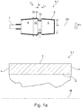
- FIG.1a A tubular cage blank 1.1 is shown, which is formed from a conventional cage material and which has a first, inner and a second, outer peripheral edge 2, 3. Furthermore, the cage blank 1.1 is laterally delimited by a first edge 4 and a second edge 5.
- This cage blank is solidly made of metal or another cage material, such as plastic.
- a milling cutter 6.1 Above the cage blank 1 there is a milling cutter 6.1, which has a drive shaft 7, a first cone 8, a second cone 9, a first cylinder 10 and a second cylinder 11. The first cone 8 axially adjoins the drive shaft 7 with its small diameter side.
- the large diameter side of the first cone 8 merges into the first cylinder 10, the diameter D1 of the first cylinder 10 and the diameter D2 on the large diameter side of the first cone 8 being the same size.
- the side of the first cylinder 10, which faces away from the large diameter side of the first cone 8, is adjoined by the second cylinder 11, which has a smaller diameter D3 than the diameter D1 of the first cylinder 10.
- the second cone 9, which has the same dimensions as the first cone 8, directly adjoins the second cylinder 11 with its large diameter side.
- the diameters of the small diameter sides of the two cones are denoted by D4.
- Both the drive shaft 7, the two cones 8, 9 and also the two cylinders 10, 11 are arranged centrally to the axis of rotation DA shown.
- the axial length L1 of the first cylinder 10 is equal to the axial length L2 of the second cylinder 10.
- the thick solid lines in Fig. 1a and b it is indicated that the lateral surfaces of the milling cutter 6.1 marked in this way are designed as cutting surfaces S.
- the small end face of the first cone 8 and the ring edge on the large end face of the second cone 9 on the large diameter side can also be designed as cutting faces S.
- the milling cutter 6.1 is lowered in the direction of arrow P1 onto the cage blank 1.1 in the direction of its central axis M, material of the cage blank 1.1 is milled away and the Fig. 1b shown ratios. It is essential in the radial movement of the milling cutter 6.1 against the cage blank 1.1 that the axis of rotation DA assumes a position at the end of the radial movement that lies between the inner peripheral edge 2 and the outer peripheral edge 3. In the embodiment according to Fig. 1b this is realized in such a way that the axis of rotation DA of the milling cutter 6.1 is at a substantially smaller distance from the inner peripheral edge 2 than from the outer peripheral edge 3. Fig.
- Fig. 1b shows a section according to BB Fig. 1c shows.
- Fig. 3c which have a section CC according Fig. 1d shows, it can be seen that the radial movement of the milling cutter 6.1 in the direction of arrow P1 ( Fig.1a ) in the first edge 4 of the cage blank 1.1 from the drive shaft 7, which, as already in connection with Fig. 1a explained, is provided on its outer surface with a cutting structure S, a cut 15 is introduced, the width B of which is narrower than the diameter D4 of the small diameter side of the first cone 8.
- This provides lateral tabs 16 which ensure that pockets 14 are formed in the pockets 14 inserted rolling elements (not shown) cannot emerge from the pockets 14 in the direction of the arrow P3.
- FIG. 2 The embodiment, which in Fig. 2 shown differs from that together with the 1a to d shown embodiment in that the cutter 6.1 penetrates far less deep radially into the cage blank 1.1.
- the milling cutter 6.1 accordingly Fig. 1b Moving in the direction of arrow P2 against the second edge 5, the overlap Ü on the second cone 9 causes an undercut-free design with a view of FIG Fig. 2 right part of the pocket 14.
- the lower penetration depth T of the milling cutter 6.1 also has the effect that, in comparison to the exemplary embodiment according to FIGS 1a to d a much larger contact surface 17 located below the axis of rotation DA is made available ( Fig. 3d ) with which - as is usual with a rolling element-guided cage - the cage runs against the rolling elements and is guided by them.
- Fig. 3b shown also formed in the embodiment according to Fig.
- Fig. 3d is a view into a pocket 14 formed without milling cutter 6.1 according to the section DD according Fig. 2 the subject.
- Fig. 3e which have a section EE Fig. 2 shows, can be removed, are provided by the radial movement in the direction of arrow P1 not only on the first edge 4 of the cage blank 1.1 rag 16. Rather, remains in accordance with the in the embodiment Fig.
- a smaller penetration depth T of the milling cutter 6.1 into the cage blank 1.1 on the inner circumferential edge of the edge 4 has a bridging 18 to which the inner circumferential edge 2 remains connected overall despite the introduction of pockets 14.
- These bridges 18 ensure that the cage blank 1.1 formed in this way cannot expand in the circumferential direction when it is used in a rolling bearing for guiding rolling bodies.
- the cage blank 1.2 can also have pre-formed pockets 14 ', which are compared to the finished ones Bags 14 are slightly smaller.
- Such pre-formed pockets 14 ' can be made available, for example, by producing the cage blank 1.2 as a cast part together with the pre-formed pockets 14'. As can be easily seen, pre-formed pockets 14 'significantly reduce the milling work.
- FIG. 5 A further milling cutter 6.2 is shown for executing the method, the lateral surface of the two cones 8, 9 not having a straight, but a curved course in the axial direction, as in the previous exemplary embodiments. Also in another embodiment (not shown) in a milling cutter 6.1 1a-c or Fig. 2 the transitions between the cones 8, 9 to the cylinders 10, 11 and the transitions between the two cylinders 10, 11 are rounded.
- Fig. 6 shows a double-row spherical roller bearing 19, in which 20 spherical rolling elements 21 are arranged between outboard bearing rings and are guided by a roller bearing cage 22 produced according to the invention, which according to the embodiment according to 1a to d was produced.
- This representation clearly shows that axially extending webs 23 extend from the second edge 5 of this roller bearing cage 22. Characterized in that this roller bearing cage 22 according to the embodiment corresponding to the 1a to d was formed, the millings 15 cut through the first edge 4 completely, so that the rolling elements 21 on the first edge 4 are secured only by the tabs 16.
Abstract
Es wird ein Verfahren zum Ausbilden von Wälzlagerkäfigen angegeben. Dabei wird ein Fräser 6.n, der einen ersten Konus 8, einen zweiten Konus 9, einen ersten Zylinder 10 und einem durchmesserkleineren Zylinder 11 aufweist, radial auf einen Käfigrohling 1.n abgesenkt. Liegt die Drehachse DA des Fräsers 6.n zwischen dem inneren und äußeren Umfangsrand 2, 3 wird der Fräser 6.n axial gegen den zweiten Rand 5 des Käfigrohlings 1.n verfahren. Anschließend wird der Fräser 6.n axial zurückverfahren und radial aus der gebildeten Tasche 14 wieder herausgefahren. Durch die Axialbewegung des Fräsers 6.n wird in einer Ringschulter 12, die durch den durchmesserkleineren Zylinder 11 beim radialen Hereinfahren des Fräser 6.n stehengeblieben war, mit einer Innenkontur 13 versehen, welche bei einem wälzkörpergeführten Wälzlagerkäfig in die Taschen 14 eingeklipste Wälzköper gegen radiales Herausfallen sichert.A method for forming roller bearing cages is specified. A milling cutter 6.n, which has a first cone 8, a second cone 9, a first cylinder 10 and a smaller-diameter cylinder 11, is lowered radially onto a cage blank 1.n. If the axis of rotation DA of the milling cutter 6.n lies between the inner and outer peripheral edge 2, 3, the milling cutter 6.n is moved axially against the second edge 5 of the cage blank 1.n. The milling cutter 6.n is then moved back axially and moved radially out of the pocket 14 formed again. Due to the axial movement of the milling cutter 6.n, an inner contour 13 is provided in an annular shoulder 12, which had stopped due to the smaller-diameter cylinder 11 when the milling cutter 6.n moved in radially, and which, in the case of a rolling element-guided rolling bearing cage, clipped the rolling element against the radial direction in the pockets 14 Falling out secures.
Description
Die Erfindung befasst sich mit der Herstellung von Wälzlagerkäfigen für Pendelrollenlager und nach diesem Verfahren hergestellten Wälzlagerkäfigen.The invention is concerned with the manufacture of roller bearing cages for spherical roller bearings and roller bearing cages produced by this method.
Allgemein bekannt ist, dass Wälzkörper, wenn sie zwischen den beiden Lagerringen angeordnet sind, von Wälzlagerkäfigen geführt werden. Diese Wälzlagerkäfige weisen zu diesem Zweck Taschen auf, in die die Wälzkörper eingesetzt werden. Je nach Anwendungsart sind diese Wälzlagerkäfige entweder an den Borden der Lageringe oder auch auf den Wälzkörpern geführt. Im ersten Fall spricht man von einer Bordführung und im zweiten Fall von einer Wälzkörperführung.It is generally known that rolling elements, if they are arranged between the two bearing rings, are guided by rolling bearing cages. For this purpose, these roller bearing cages have pockets in which the roller bodies are inserted. Depending on the type of application, these roller bearing cages are either guided on the rims of the bearing rings or on the roller bodies. In the first case one speaks of an on-board guidance and in the second case of a rolling element guidance.
Wälzlagerkäfige sind allgemein aus Metall oder Kunststoff gebildet. Während bei Wälzlagerkäfigen die erforderlichen Taschen in der Regel gleich mit dem Spritzvorgang eingebracht werden, müssen bei Wälzlagerkäfigen aus Metall diese Taschen durch nachfolgende Bearbeitungsschritte in den jeweiligen Käfigrohlingen hergestellt werden, da bekannte Metallgussverfahren nicht geeignet sind, Wälzlagerkäfige bzw. deren Taschen in der gewünschten Genauigkeit und/oder Oberflächengüte herzustellen. Handelt es sich um Wälzlagerkäfige, die aus Blech gebildet werden, werden die notwendigen Taschen in der Regel durch Stanzen hergestellt. Da Blechkäfige aber nur bei geringen Belastungen des Wälzlagers zuverlässig eingesetzt werden können, werden für höhere Wälzlagerbelastungen in der Regel rohrförmige Käfigrohlinge aus beispielsweise Messing oder Eisenguss verwendet, in welchen dann durch Fräsen die erforderlichen Taschen herausgearbeitet werden. Dazu werden allgemein Fingerfräser eingesetzt, mit welchen die Konturen der zu bildenden Taschen abgefahren werden. Wie leicht einzusehen ist, ist das Abfahren der Konturen der zu bildenden Taschen mit erheblichem Zeitaufwand verbunden.Rolling cages are generally made of metal or plastic. While the necessary pockets for roller bearing cages are usually inserted immediately with the spraying process, these pockets have to be produced in the respective cage blanks for roller bearing cages made of metal by subsequent processing steps, since known metal casting processes are not suitable, roller bearing cages or their pockets in the desired accuracy and / or to produce surface quality. If the bearing cages are made of sheet metal, the necessary pockets are usually made by stamping. However, since sheet metal cages can only be used reliably when the rolling bearing is subjected to low loads, tubular cage blanks made of, for example, brass or cast iron are generally used for higher rolling bearing loads, in which the necessary pockets are then worked out by milling. For this purpose, end mills are generally used, with which the contours of the pockets to be formed are traversed. As is easy to see, traversing the contours of the pockets to be formed takes a considerable amount of time.
Oftmals müssen auch verschiedene Fingerfräser eingesetzt werden, um die gewünschte Taschenkontur herzustellen, was entsprechende hohe Rüstzeiten zur Folge hat.Often, different end mills must also be used to produce the desired pocket contour, which results in correspondingly long set-up times.
Dies insbesondere dann, wenn die in Taschen eingesetzten Wälzkörper eines wälzkörpergeführten Wälzlagerkäfigs nach der Montage dort selbsthaltend angeordnet bleiben sollen. Denn um diese zu realisiere, müssen die Taschen an ihrer radialen Innenseite als auch an ihrer radialen Außenseite Einschnürungen aufweisen, die in die Taschen eingesetzte Wälzkörper an radial entgegengesetzten Seiten umgreifen.This is particularly the case if the rolling elements of a rolling element bearing cage used in pockets are to be arranged there in a self-retaining manner after assembly. Because in order to achieve this, the pockets must have constrictions on their radial inside as well as on their radial outside, which encompass rolling elements inserted into the pockets on radially opposite sides.
Daher liegt der Erfindung die Aufgabe zugrunde, ein vereinfachtes Verfahren zur Ausbildung eines wälzlagergeführten Wälzlagerkäfigs eines Pendelrollenlagers anzugeben.The invention is therefore based on the object of specifying a simplified method for forming a roller bearing cage in a spherical roller bearing.
Diese Aufgabe wird mit den in Anspruch 1 angegebenen Merkmalen gelöst. Vorteilhafte Aus- und Weiterbildungen der Erfindung sind den Ansprüchen 2 bis 6 entnehmbar. Ein nach dem Verfahren hergestellter Wälzlagerkäfig sowie ein, einen solchen Wälzlagerkäfig enthaltendes Pendelrollenlager finden sich in den Ansprüchen 7 und 8.This object is achieved with the features specified in claim 1. Advantageous further developments of the invention can be found in
Ausgegangen wird von der Bereitstellung eines rohrförmigeren Käfigrohlings mit einem ersten und einem zweiten Rand und einem inneren und einem äußeren Umfangsrand und eines Fräsers, wobei der Fräser einen Antriebsschaft und Schneidflächen aufweist.The starting point is the provision of a more tubular cage blank with a first and a second edge and an inner and an outer peripheral edge and a milling cutter, the milling cutter having a drive shaft and cutting surfaces.
Wird der Fräser, welcher einen axial an den Antriebsschaft anschließenden ersten Konus, einen an die Großdurchmesserseite des ersten Konus anschließenden ersten Zylinder, einen zweiten Konus, dessen Großdurchmesserseite in Richtung der Großdurchmesserseite des ersten Konus weist, und einem zweiten Zylinder, welcher gegenüber dem Durchmesser D1 des ersten Zylinders einen verminderten Durchmesser D3 hat und welcher innerhalb der axialen Erstreckung des ersten Zylinders zwischen den beiden Großdurchmesserseiten der beiden Konen angeordnet ist, hat, und welcher mindestens an den Mantelflächen der beiden Konen und der beiden Zylinder Schneidflächen bereitstellt, radial solange gegen die Mittelachse des Käfigrohlings verfahren wird, bis die Drehachse DA des Fräsers eine Position eingenommen hat, die zwischen dem inneren und dem äußeren Umfangsrand des Käfigrohlings liegt, dann in der im Käfigrohling eingetauchten Position axial gegen den zweiten Rand verfahren wird, anschließend wieder gegen den ersten Rand verfahren wird, bis dieser wieder eine Position eingenommen hat, den dieser vor dem axialen Verfahren gegen den zweiten Rand hatte, und wieder radial aus dem Käfigrohling herausgefahren, wird die erforderliche Taschenkontur quasi in einem Zug mit nur einem Fräser hergestellt. Dadurch, dass die Drehachse des Fräsers nicht vollständig die Dicke zwischen dem inneren und äußeren Umfangsrand des Käfigrohlings beim radialen Absenken durchfährt, erhält nicht nur der Bereich des Käfigrohlings, der unterhalb der Drehachse DA des Fräsers liegt, eine gerundete, den lichten Querschnitt einschnürende Rampen, die später den im Wälzlager verbauten Wälzlagerkäfig auf den Wälzkörpern führen, sondern auch der oberhalb der Drehachse des Fräser liegende Bereich des Käfigrohlings, indem die als Folge des durchmesserkleineren zweiten Zylinders nach dem radialen Hereinfahren des Fräsers verbleibende Ringschulter durch das axiale Verfahren des Fräsers mittels des durchmessergrößeren ersten Zylinders eine gerundete Innenkontur erhält, die bei einem in eine solche Tasche eingebrachten Wälzkörper diesen gegen radiales Herausfallen nach außen sichert. Da die axiale Breite der Ringschulter nur gering ist, lassen sich gegen den Widerstand der Ringschulter von radial außen Wälzkörper in die so gebildeten Taschen problemlos einschnappen.If the milling cutter, which has a first cone axially adjoining the drive shaft, a first cylinder adjoining the large diameter side of the first cone, a second cone, the large diameter side of which points in the direction of the large diameter side of the first cone, and a second cylinder which is opposite the diameter D1 of the first cylinder has a reduced diameter D3 and which is arranged within the axial extent of the first cylinder between the two large diameter sides of the two cones, and which provides cutting surfaces at least on the lateral surfaces of the two cones and the two cylinders, radially as long as against the central axis the cage blank is moved until the axis of rotation DA of the milling cutter has assumed a position, which lies between the inner and the outer circumferential edge of the cage blank, is then moved axially against the second edge in the position immersed in the cage blank, then is moved again against the first edge until it has again assumed a position which it had before the axial movement against the second edge, and again radially out of the cage blank, the required pocket contour is produced in one go with only one milling cutter. Due to the fact that the axis of rotation of the milling cutter does not completely pass through the thickness between the inner and outer peripheral edge of the cage blank during the radial lowering, not only the area of the cage blank that lies below the axis of rotation DA of the milling cutter receives a rounded ramps that constrict the clear cross section, which later guide the rolling bearing cage installed in the rolling bearing on the rolling elements, but also the area of the cage blank above the axis of rotation of the milling cutter, as a result of the ring shoulder remaining as a result of the smaller-diameter second cylinder after the milling cutter has been radially moved in by the axial movement of the milling cutter by means of the larger diameter The first cylinder receives a rounded inner contour which, when a rolling element is inserted into such a pocket, secures it against radial falling outwards. Since the axial width of the ring shoulder is only small, rolling elements can be snapped into the pockets formed in this way without any problems, against the resistance of the ring shoulder.
Eine symmetrische Taschenform ist gegeben, wenn der zweite Zylinder des Fräsers unmittelbar an die Großdurchmesserseite des zweiten Konus des Fräsers anschließt,
dass die axiale Breite L1 des ersten Zylinders der axialen Breite L2 des zweiten Zylinders entspricht, und der Fräser axial gegen den zweiten Rand um das Maß der axialen Breite L1 verfahren wird.A symmetrical pocket shape is given if the second cylinder of the milling cutter directly adjoins the large diameter side of the second cone of the milling cutter,
that the axial width L1 of the first cylinder corresponds to the axial width L2 of the second cylinder, and the milling cutter is moved axially against the second edge by the amount of the axial width L1.
Hinterschneidungen an Taschen werden vermieden, wenn die Eindringtiefe T der Drehachse DA des Fräsers gleich oder kleiner dem Durchmesser D5 der Konen an deren Kleindurchmesserseite ist.Undercuts on pockets are avoided if the depth of penetration T of the axis of rotation DA of the milling cutter is equal to or less than the diameter D5 of the cones on their small diameter side.
Ist die Mantelfläche des axial an die Kleindurchmesserseite des ersten Konus anschließenden Antriebsschafts 7 ebenfalls mit einer Schneidfläche S versehen, furcht sich der Antriebsschaft bei der Radialbewegung des Fräsers selbst seinen Weg im Käfigrohling.If the outer surface of the
Der Zerspanungsleistung ist verbessert, wenn auch die beiden Stirnflächen des ersten Konus und zumindest die Kleindurchmesserstirnfläche des zweiten Konus Schneidflächen S aufweist.The cutting performance is improved if the two end faces of the first cone and at least the small diameter end face of the second cone also have cutting faces S.
Die Fräsarbeit ist reduziert, wenn der Käfigrohling vorgebildete Taschen aufweist, die etwas kleiner sind als die endgültigen Abmessungen der Taschen,, die mittels des Fräsers eingebracht werden.The milling work is reduced if the cage blank has pre-formed pockets that are somewhat smaller than the final dimensions of the pockets, which are introduced by means of the milling cutter.
Es zeigen:
- Fig.1a -d
- vier Bearbeitungsstufen eines Wälzlagerkäfigs im Seitenschnitt;
- Fig.2
- eine Bearbeitungsstufe eines weiteren Wälzlagerkäfigs;
- Fig. 3a-e
- Schnitte gemäß
Fig. 1a-d undFig. 2 - Fig. 4
- einen weiteren Käfigrohling im Seitenschnittt;
- Fig. 5
- einen weiteren Fräser; und
- Fig. 6
- ein Pendelrollenlager
- Fig.1a-d
- four processing stages of a rolling bearing cage in side section;
- Fig. 2
- a processing stage of another roller bearing cage;
- 3a-e
- Cuts according to
1a-d andFig. 2 - Fig. 4
- another cage blank in side cut;
- Fig. 5
- another router; and
- Fig. 6
- a spherical roller bearing
Die Erfindung soll nun anhand der Figuren näher erläutert werden.The invention will now be explained in more detail with reference to the figures.
In
Wird ausgehend von
Ausgehend von der in
Ist die Innenkontur 13 in der Ringschulter 12 durch Bewegung in Pfeilrichtung P2 ausgebildet, wird der Fräser 6.1 in Pfeilrichtung P3 (
Das Ausführungsbeispiel, welches in
Auch wenn in den bisher beschriebenen Ausführungsbeispielen immer von einem massiven Käfigrohling 1.1 ausgegangen wurde, in welchen die Taschen 14 eingefräst wurden, so ist die Erfindung nicht darauf festgelegt. Wie
In
- 1.n1.n
- rohrförmiger Käfigrohlingtubular cage blank
- 22nd
- innerer Umfangsrandinner peripheral edge
- 33rd
- äußerer Umfangsrandouter peripheral edge
- 44th
- erster Randfirst edge
- 55
- zweiter Randsecond margin
- 66
- FräserCutter
- 77
- AntriebsschaftDrive shaft
- 88th
- erster Konusfirst cone
- 99
- zweiter Konussecond cone
- 1010th
- erster Zylinderfirst cylinder
- 1111
- zweiter Zylindersecond cylinder
- 1212
- RingschulterRing shoulder
- 1313
- InnenkonurInner contour
- 1414
- Taschebag
- 1515
- EinfräsungMilling
- 1616
- LappenRag
- 1717th
- AnlaufflächeContact area
- 1818th
- ÜberbrückungBridging
- 1919th
- PendelrollenlagerSpherical roller bearings
- 2020th
- LagerringeBearing rings
- 2121st
- WälzkörperRolling elements
Claims (8)
bei welchem ein rohrförmiger Käfigrohling 1.n mit einem ersten und einem zweiten Rand 4, 5 und einem inneren und einem äußeren Umfangsrand 2, 3 und ein Fräser 6.n bereitgestellt werden, wobei der Fräser 6.n einen Antriebsschaft 7 und Schneidflächen S aufweist,
dadurch gekennzeichnet,
dass der Fräser 6.n , welcher einen axial an den Antriebsschaft 7 anschließenden ersten Konus 8, einen an die Großdurchmesserseite des ersten Konus 8 anschließenden ersten Zylinder 10, einen zweiten Konus 9, dessen Großdurchmesserseite in Richtung der Großdurchmesserseite des ersten Konus 8 weist, und einen zweiten Zylinder 11, welcher gegenüber dem Durchmesser D1 des ersten Zylinders einen verminderten Durchmesser D3 hat und welcher innerhalb der axialen Erstreckung des ersten Zylinders 10 zwischen den beiden Großdurchmesserseiten der beiden Konen 8, 9 angeordnet ist, und welcher mindestens an den Mantelflächen der beiden Konen 8, 9 und der beiden Zylinder 10, 11 Schneidflächen S aufweist, radial solange gegen die Mittelachse M des Käfigrohlings 1.n verfahren wird, bis die Drehachse DA des Fräsers 6.n eine Position eingenommen hat, die zwischen dem inneren und dem äußeren Umfangsrand 2, 3 des Käfigrohlings 1.n liegt,
dass dann der Fräser 6.n in der im Käfigrohling 1.n eingetauchten Position axial gegen den zweiten Rand 5 verfahren wird,
dass anschließend der Fräser 6.n axial gegen den ersten Rand 4 verfahren wird, bis dieser wieder eine Position eingenommen hat, den dieser vor dem axialen Verfahren gegen den zweiten Rand 5 hatte, und
dass dann der Fräser 6.n radial aus dem Käfigrohling 1.n herausgefahren wird.Process for the production of a spherical roller bearing cage,
in which a tubular cage blank 1.n with a first and a second edge 4, 5 and an inner and an outer peripheral edge 2, 3 and a milling cutter 6.n are provided, the milling cutter 6.n having a drive shaft 7 and cutting surfaces S. ,
characterized,
that the milling cutter 6.n, which has a first cone 8 axially adjoining the drive shaft 7, a first cylinder 10 adjoining the large-diameter side of the first cone 8, a second cone 9, the large-diameter side of which points in the direction of the large-diameter side of the first cone 8, and a second cylinder 11, which has a reduced diameter D3 compared to the diameter D1 of the first cylinder and which is arranged within the axial extent of the first cylinder 10 between the two large diameter sides of the two cones 8, 9, and which is at least on the lateral surfaces of the two cones 8, 9 and the two cylinders 10, 11 has cutting surfaces S, is moved radially against the central axis M of the cage blank 1.n until the axis of rotation DA of the milling cutter 6.n has assumed a position between the inner and the outer peripheral edge 2, 3 of the cage blank 1.n lies,
that the cutter 6.n is then moved axially against the second edge 5 in the position immersed in the cage blank 1.n,
that the milling cutter 6.n is then moved axially against the first edge 4 until it has again assumed a position which it had against the second edge 5 before the axial movement, and
that the cutter 6.n is then moved radially out of the cage blank 1.n.
dadurch gekennzeichnet,
dass der zweite Zylinder 11 des Fräsers 6.n unmittelbar an die Großdurchmesserseite des zweiten Konus 9 des Fräsers 6.n anschließt,
dass die axiale Breite L1 des ersten Zylinders 10 der axialen Breite L2 des zweiten Zylinders 11 entspricht, und
dass der Fräser 6.n axial gegen den zweiten Rand 5 um das Maß der axialen Breite L1 des ersten Zylinders 10 verfahren wird.The method of claim 1
characterized,
that the second cylinder 11 of the milling cutter 6.n directly adjoins the large diameter side of the second cone 9 of the milling cutter 6.n,
that the axial width L1 of the first cylinder 10 of the axial width L2 of the corresponds to second cylinder 11, and
that the cutter 6.n is moved axially against the second edge 5 by the amount of the axial width L1 of the first cylinder 10.
durch gekennzeichnet,
dass die Eindringtiefe T der Drehachse DA des Fräsers 6.n gleich oder kleiner dem Durchmesser D5 der Konen 8, 9 an deren Kleindurchmesserseite ist.A method according to claim 1 or claim 2
characterized by
that the depth of penetration T of the axis of rotation DA of the milling cutter 6.n is equal to or smaller than the diameter D5 of the cones 8, 9 on their small diameter side.
dadurch gekennzeichnet,
dass die Mantelfläche des axial an die Kleindurchmesserseite des ersten Konus 8 anschließenden Antriebsschafts 7 ebenfalls eine Schneidfläche S aufweist.A method according to claim 1 or claim 3
characterized,
that the outer surface of the drive shaft 7 axially adjoining the small diameter side of the first cone 8 also has a cutting surface S.
dadurch gekennzeichnet,
dass auch die beiden Stirnflächen des ersten Konus 8 und zumindest die Kleindurchmesserstirnfläche des zweiten Konus Schneidflächen S aufweist.Method according to one of claims 1 to 4
characterized,
that the two end faces of the first cone 8 and at least the small diameter end face of the second cone have cutting surfaces S.
dadurch gekennzeichnet,
dass der Käfigrohling 1.2 vorgebildete Taschen 14'aufweist.Method according to one of claims 1 to 5
characterized,
that the cage blank 1.2 has pre-formed pockets 14 '.
dass jeder der beiden Lagerringe 20 außenbordfrei ausgebildet ist.Spherical roller bearings containing a roller bearing cage according to claim 7, characterized in
that each of the two bearing rings 20 is designed without an outboard.
Applications Claiming Priority (1)
| Application Number | Priority Date | Filing Date | Title |
|---|---|---|---|
| DE102018129894.3A DE102018129894A1 (en) | 2018-11-27 | 2018-11-27 | Method of manufacturing a spherical roller bearing cage and a roller bearing cage produced by the method |
Publications (2)
| Publication Number | Publication Date |
|---|---|
| EP3660344A1 true EP3660344A1 (en) | 2020-06-03 |
| EP3660344B1 EP3660344B1 (en) | 2021-06-30 |
Family
ID=68655374
Family Applications (1)
| Application Number | Title | Priority Date | Filing Date |
|---|---|---|---|
| EP19211208.4A Active EP3660344B1 (en) | 2018-11-27 | 2019-11-25 | Method for the manufacturing of a spherical roller bearing cage and a rolling bearing cage manufactured by the method |
Country Status (2)
| Country | Link |
|---|---|
| EP (1) | EP3660344B1 (en) |
| DE (1) | DE102018129894A1 (en) |
Families Citing this family (1)
| Publication number | Priority date | Publication date | Assignee | Title |
|---|---|---|---|---|
| DE102022109860B3 (en) | 2022-04-25 | 2023-01-12 | Ringspann Gmbh | CAGE FREEWHEEL WITH BEARING ROLLERS |
Citations (2)
| Publication number | Priority date | Publication date | Assignee | Title |
|---|---|---|---|---|
| US3290102A (en) * | 1960-03-05 | 1966-12-06 | Skf Svenska Kullagerfab Ab | Spherical roller bearing with barrel-shaped rollers |
| DE102016202919A1 (en) * | 2016-02-25 | 2017-08-31 | Schaeffler Technologies AG & Co. KG | Spherical roller bearings |
Family Cites Families (7)
| Publication number | Priority date | Publication date | Assignee | Title |
|---|---|---|---|---|
| GB2242147B (en) * | 1990-03-22 | 1993-07-28 | Skf Gmbh | A device for forming pockets in cages |
| DE4009171A1 (en) * | 1990-03-22 | 1991-09-26 | Skf Gmbh | DEVICE FOR TENSIONING TUBULAR INTERMEDIATE PRODUCTS |
| DE4228322A1 (en) * | 1992-08-26 | 1994-03-03 | Guenther Wirth | Drilling and endmilling tool for producing chamfered and profiled holes - has drill tip followed by reduced form milling section with shoulders allowing both ends of hole to be chamfered when tool is eccentrically rotated |
| US8007184B2 (en) * | 2004-11-24 | 2011-08-30 | Nsk Ltd. | Self-aligning roller bearing with retainer and manufacturing method for self-aligning roller bearing retainer |
| JP2006266277A (en) * | 2005-03-22 | 2006-10-05 | Nsk Ltd | Self-aligning roller bearing with cage |
| DE102010020019B4 (en) * | 2010-05-10 | 2012-05-31 | Gebr. Reinfurt Gmbh & Co. Kg | Method for producing a ball-guided snap cage made of plastic material |
| JP2012002306A (en) * | 2010-06-18 | 2012-01-05 | Ntn Corp | Cage for self-aligning roller bearing and assembling method for self-aligning roller bearing |
-
2018
- 2018-11-27 DE DE102018129894.3A patent/DE102018129894A1/en not_active Withdrawn
-
2019
- 2019-11-25 EP EP19211208.4A patent/EP3660344B1/en active Active
Patent Citations (2)
| Publication number | Priority date | Publication date | Assignee | Title |
|---|---|---|---|---|
| US3290102A (en) * | 1960-03-05 | 1966-12-06 | Skf Svenska Kullagerfab Ab | Spherical roller bearing with barrel-shaped rollers |
| DE102016202919A1 (en) * | 2016-02-25 | 2017-08-31 | Schaeffler Technologies AG & Co. KG | Spherical roller bearings |
Also Published As
| Publication number | Publication date |
|---|---|
| DE102018129894A1 (en) | 2020-05-28 |
| EP3660344B1 (en) | 2021-06-30 |
Similar Documents
| Publication | Publication Date | Title |
|---|---|---|
| DE102011112148B4 (en) | Extruder and process for producing an extruder | |
| DE112011101552B4 (en) | Axial cage for cylindrical rolling elements | |
| DE102010022512B4 (en) | Plain bearings for internal combustion engines | |
| DE19654584B4 (en) | Cage for needle roller bearings and method for its production | |
| DE10107109A1 (en) | Collar bushing, process for its manufacture and bending tool for the production of coils on a bushing | |
| DE102011003211A1 (en) | roller bearing | |
| DE112015004960T5 (en) | Tapered roller bearings | |
| EP2893207B1 (en) | Axial cage for cylindrical rolling elements | |
| DE112015004932T5 (en) | Tapered roller bearings | |
| EP3660344B1 (en) | Method for the manufacturing of a spherical roller bearing cage and a rolling bearing cage manufactured by the method | |
| DE102011087444A1 (en) | Method for producing bearing component e.g. outer ring of rolling bearing, involves punching lubrication holes in solid ring which is formed by cutting processing such as rotating, precision turning, forging or rolling | |
| EP2550463B1 (en) | Bearing ring | |
| DE19936014A1 (en) | Rubber bearing with axial damping | |
| DE112015004945T5 (en) | BEARING | |
| WO2008074560A2 (en) | Method for the production of a synchronizer ring of a synchronizing device | |
| DE2014420B2 (en) | Snap fit roller bearing cage - has pocket finger projections formed into radial lubricant grooves in pocket wall centres | |
| DE112015004946T5 (en) | BEARING | |
| DE102018101551A1 (en) | Cage for a rolling bearing, method of manufacturing the cage and a cage blank | |
| DE965459C (en) | Needle roller cage | |
| DE102008050231A1 (en) | Rolling body i.e. ball, for roller bearing, has cavity and two openings that lie opposite to each other, where body is in form of ball whose surface is flattened in region of openings | |
| DE102009050524A1 (en) | Radial roller bearings | |
| WO2007088144A2 (en) | Double-row thin ring bearing comprising inclined rolls | |
| DE19517217C2 (en) | Solid window cage for a needle bearing | |
| DE102004055227A1 (en) | Tapered roller bearings | |
| DE102018128075B4 (en) | Method for forming a raceway superelevation on a bearing ring, a clutch release bearing produced according to the method and a tool set |
Legal Events
| Date | Code | Title | Description |
|---|---|---|---|
| PUAI | Public reference made under article 153(3) epc to a published international application that has entered the european phase |
Free format text: ORIGINAL CODE: 0009012 |
|
| STAA | Information on the status of an ep patent application or granted ep patent |
Free format text: STATUS: THE APPLICATION HAS BEEN PUBLISHED |
|
| AK | Designated contracting states |
Kind code of ref document: A1 Designated state(s): AL AT BE BG CH CY CZ DE DK EE ES FI FR GB GR HR HU IE IS IT LI LT LU LV MC MK MT NL NO PL PT RO RS SE SI SK SM TR |
|
| AX | Request for extension of the european patent |
Extension state: BA ME |
|
| STAA | Information on the status of an ep patent application or granted ep patent |
Free format text: STATUS: REQUEST FOR EXAMINATION WAS MADE |
|
| 17P | Request for examination filed |
Effective date: 20201203 |
|
| RBV | Designated contracting states (corrected) |
Designated state(s): AL AT BE BG CH CY CZ DE DK EE ES FI FR GB GR HR HU IE IS IT LI LT LU LV MC MK MT NL NO PL PT RO RS SE SI SK SM TR |
|
| GRAP | Despatch of communication of intention to grant a patent |
Free format text: ORIGINAL CODE: EPIDOSNIGR1 |
|
| STAA | Information on the status of an ep patent application or granted ep patent |
Free format text: STATUS: GRANT OF PATENT IS INTENDED |
|
| INTG | Intention to grant announced |
Effective date: 20210315 |
|
| GRAS | Grant fee paid |
Free format text: ORIGINAL CODE: EPIDOSNIGR3 |
|
| GRAA | (expected) grant |
Free format text: ORIGINAL CODE: 0009210 |
|
| STAA | Information on the status of an ep patent application or granted ep patent |
Free format text: STATUS: THE PATENT HAS BEEN GRANTED |
|
| AK | Designated contracting states |
Kind code of ref document: B1 Designated state(s): AL AT BE BG CH CY CZ DE DK EE ES FI FR GB GR HR HU IE IS IT LI LT LU LV MC MK MT NL NO PL PT RO RS SE SI SK SM TR |
|
| REG | Reference to a national code |
Ref country code: CH Ref legal event code: EP |
|
| REG | Reference to a national code |
Ref country code: AT Ref legal event code: REF Ref document number: 1406608 Country of ref document: AT Kind code of ref document: T Effective date: 20210715 |
|
| REG | Reference to a national code |
Ref country code: DE Ref legal event code: R096 Ref document number: 502019001723 Country of ref document: DE |
|
| REG | Reference to a national code |
Ref country code: IE Ref legal event code: FG4D Free format text: LANGUAGE OF EP DOCUMENT: GERMAN |
|
| REG | Reference to a national code |
Ref country code: RO Ref legal event code: EPE |
|
| REG | Reference to a national code |
Ref country code: SE Ref legal event code: TRGR |
|
| REG | Reference to a national code |
Ref country code: LT Ref legal event code: MG9D |
|
| PG25 | Lapsed in a contracting state [announced via postgrant information from national office to epo] |
Ref country code: BG Free format text: LAPSE BECAUSE OF FAILURE TO SUBMIT A TRANSLATION OF THE DESCRIPTION OR TO PAY THE FEE WITHIN THE PRESCRIBED TIME-LIMIT Effective date: 20210930 Ref country code: FI Free format text: LAPSE BECAUSE OF FAILURE TO SUBMIT A TRANSLATION OF THE DESCRIPTION OR TO PAY THE FEE WITHIN THE PRESCRIBED TIME-LIMIT Effective date: 20210630 Ref country code: HR Free format text: LAPSE BECAUSE OF FAILURE TO SUBMIT A TRANSLATION OF THE DESCRIPTION OR TO PAY THE FEE WITHIN THE PRESCRIBED TIME-LIMIT Effective date: 20210630 |
|
| REG | Reference to a national code |
Ref country code: NL Ref legal event code: MP Effective date: 20210630 |
|
| PG25 | Lapsed in a contracting state [announced via postgrant information from national office to epo] |
Ref country code: GR Free format text: LAPSE BECAUSE OF FAILURE TO SUBMIT A TRANSLATION OF THE DESCRIPTION OR TO PAY THE FEE WITHIN THE PRESCRIBED TIME-LIMIT Effective date: 20211001 Ref country code: RS Free format text: LAPSE BECAUSE OF FAILURE TO SUBMIT A TRANSLATION OF THE DESCRIPTION OR TO PAY THE FEE WITHIN THE PRESCRIBED TIME-LIMIT Effective date: 20210630 Ref country code: LV Free format text: LAPSE BECAUSE OF FAILURE TO SUBMIT A TRANSLATION OF THE DESCRIPTION OR TO PAY THE FEE WITHIN THE PRESCRIBED TIME-LIMIT Effective date: 20210630 Ref country code: NO Free format text: LAPSE BECAUSE OF FAILURE TO SUBMIT A TRANSLATION OF THE DESCRIPTION OR TO PAY THE FEE WITHIN THE PRESCRIBED TIME-LIMIT Effective date: 20210930 |
|
| PG25 | Lapsed in a contracting state [announced via postgrant information from national office to epo] |
Ref country code: CZ Free format text: LAPSE BECAUSE OF FAILURE TO SUBMIT A TRANSLATION OF THE DESCRIPTION OR TO PAY THE FEE WITHIN THE PRESCRIBED TIME-LIMIT Effective date: 20210630 Ref country code: SM Free format text: LAPSE BECAUSE OF FAILURE TO SUBMIT A TRANSLATION OF THE DESCRIPTION OR TO PAY THE FEE WITHIN THE PRESCRIBED TIME-LIMIT Effective date: 20210630 Ref country code: PT Free format text: LAPSE BECAUSE OF FAILURE TO SUBMIT A TRANSLATION OF THE DESCRIPTION OR TO PAY THE FEE WITHIN THE PRESCRIBED TIME-LIMIT Effective date: 20211102 Ref country code: NL Free format text: LAPSE BECAUSE OF FAILURE TO SUBMIT A TRANSLATION OF THE DESCRIPTION OR TO PAY THE FEE WITHIN THE PRESCRIBED TIME-LIMIT Effective date: 20210630 Ref country code: SK Free format text: LAPSE BECAUSE OF FAILURE TO SUBMIT A TRANSLATION OF THE DESCRIPTION OR TO PAY THE FEE WITHIN THE PRESCRIBED TIME-LIMIT Effective date: 20210630 Ref country code: ES Free format text: LAPSE BECAUSE OF FAILURE TO SUBMIT A TRANSLATION OF THE DESCRIPTION OR TO PAY THE FEE WITHIN THE PRESCRIBED TIME-LIMIT Effective date: 20210630 Ref country code: EE Free format text: LAPSE BECAUSE OF FAILURE TO SUBMIT A TRANSLATION OF THE DESCRIPTION OR TO PAY THE FEE WITHIN THE PRESCRIBED TIME-LIMIT Effective date: 20210630 |
|
| PG25 | Lapsed in a contracting state [announced via postgrant information from national office to epo] |
Ref country code: PL Free format text: LAPSE BECAUSE OF FAILURE TO SUBMIT A TRANSLATION OF THE DESCRIPTION OR TO PAY THE FEE WITHIN THE PRESCRIBED TIME-LIMIT Effective date: 20210630 |
|
| REG | Reference to a national code |
Ref country code: DE Ref legal event code: R097 Ref document number: 502019001723 Country of ref document: DE |
|
| PG25 | Lapsed in a contracting state [announced via postgrant information from national office to epo] |
Ref country code: DK Free format text: LAPSE BECAUSE OF FAILURE TO SUBMIT A TRANSLATION OF THE DESCRIPTION OR TO PAY THE FEE WITHIN THE PRESCRIBED TIME-LIMIT Effective date: 20210630 |
|
| PLBE | No opposition filed within time limit |
Free format text: ORIGINAL CODE: 0009261 |
|
| STAA | Information on the status of an ep patent application or granted ep patent |
Free format text: STATUS: NO OPPOSITION FILED WITHIN TIME LIMIT |
|
| PG25 | Lapsed in a contracting state [announced via postgrant information from national office to epo] |
Ref country code: AL Free format text: LAPSE BECAUSE OF FAILURE TO SUBMIT A TRANSLATION OF THE DESCRIPTION OR TO PAY THE FEE WITHIN THE PRESCRIBED TIME-LIMIT Effective date: 20210630 |
|
| REG | Reference to a national code |
Ref country code: DE Ref legal event code: R119 Ref document number: 502019001723 Country of ref document: DE |
|
| 26N | No opposition filed |
Effective date: 20220331 |
|
| PG25 | Lapsed in a contracting state [announced via postgrant information from national office to epo] |
Ref country code: MC Free format text: LAPSE BECAUSE OF FAILURE TO SUBMIT A TRANSLATION OF THE DESCRIPTION OR TO PAY THE FEE WITHIN THE PRESCRIBED TIME-LIMIT Effective date: 20210630 |
|
| PG25 | Lapsed in a contracting state [announced via postgrant information from national office to epo] |
Ref country code: LU Free format text: LAPSE BECAUSE OF NON-PAYMENT OF DUE FEES Effective date: 20211125 Ref country code: BE Free format text: LAPSE BECAUSE OF NON-PAYMENT OF DUE FEES Effective date: 20211130 |
|
| REG | Reference to a national code |
Ref country code: BE Ref legal event code: MM Effective date: 20211130 |
|
| PG25 | Lapsed in a contracting state [announced via postgrant information from national office to epo] |
Ref country code: IE Free format text: LAPSE BECAUSE OF NON-PAYMENT OF DUE FEES Effective date: 20211125 Ref country code: DE Free format text: LAPSE BECAUSE OF NON-PAYMENT OF DUE FEES Effective date: 20220601 |
|
| PG25 | Lapsed in a contracting state [announced via postgrant information from national office to epo] |
Ref country code: LT Free format text: LAPSE BECAUSE OF FAILURE TO SUBMIT A TRANSLATION OF THE DESCRIPTION OR TO PAY THE FEE WITHIN THE PRESCRIBED TIME-LIMIT Effective date: 20210630 |
|
| P01 | Opt-out of the competence of the unified patent court (upc) registered |
Effective date: 20230522 |
|
| PG25 | Lapsed in a contracting state [announced via postgrant information from national office to epo] |
Ref country code: CY Free format text: LAPSE BECAUSE OF FAILURE TO SUBMIT A TRANSLATION OF THE DESCRIPTION OR TO PAY THE FEE WITHIN THE PRESCRIBED TIME-LIMIT Effective date: 20210630 |
|
| REG | Reference to a national code |
Ref country code: CH Ref legal event code: PL |
|
| PG25 | Lapsed in a contracting state [announced via postgrant information from national office to epo] |
Ref country code: LI Free format text: LAPSE BECAUSE OF NON-PAYMENT OF DUE FEES Effective date: 20221130 Ref country code: HU Free format text: LAPSE BECAUSE OF FAILURE TO SUBMIT A TRANSLATION OF THE DESCRIPTION OR TO PAY THE FEE WITHIN THE PRESCRIBED TIME-LIMIT; INVALID AB INITIO Effective date: 20191125 Ref country code: CH Free format text: LAPSE BECAUSE OF NON-PAYMENT OF DUE FEES Effective date: 20221130 |
|
| PGFP | Annual fee paid to national office [announced via postgrant information from national office to epo] |
Ref country code: SE Payment date: 20231120 Year of fee payment: 5 Ref country code: RO Payment date: 20231116 Year of fee payment: 5 Ref country code: IT Payment date: 20231124 Year of fee payment: 5 Ref country code: FR Payment date: 20231120 Year of fee payment: 5 |