EP3660344A1 - Procede de production d'une cage de roulement a rouleaux spheriques et cage de roulement produite selon ce procede - Google Patents
Procede de production d'une cage de roulement a rouleaux spheriques et cage de roulement produite selon ce procede Download PDFInfo
- Publication number
- EP3660344A1 EP3660344A1 EP19211208.4A EP19211208A EP3660344A1 EP 3660344 A1 EP3660344 A1 EP 3660344A1 EP 19211208 A EP19211208 A EP 19211208A EP 3660344 A1 EP3660344 A1 EP 3660344A1
- Authority
- EP
- European Patent Office
- Prior art keywords
- milling cutter
- cone
- cylinder
- cage
- edge
- Prior art date
- Legal status (The legal status is an assumption and is not a legal conclusion. Google has not performed a legal analysis and makes no representation as to the accuracy of the status listed.)
- Granted
Links
- 238000005096 rolling process Methods 0.000 title claims abstract description 30
- 238000000034 method Methods 0.000 title claims abstract description 15
- 238000004519 manufacturing process Methods 0.000 title claims description 3
- 238000003801 milling Methods 0.000 claims abstract description 55
- 230000002093 peripheral effect Effects 0.000 claims abstract description 13
- 238000005520 cutting process Methods 0.000 claims description 13
- 230000035515 penetration Effects 0.000 claims description 5
- 239000002184 metal Substances 0.000 description 5
- 229910052751 metal Inorganic materials 0.000 description 5
- 239000000463 material Substances 0.000 description 3
- 230000004323 axial length Effects 0.000 description 2
- 230000007704 transition Effects 0.000 description 2
- 229910001369 Brass Inorganic materials 0.000 description 1
- 229910001018 Cast iron Inorganic materials 0.000 description 1
- 239000010951 brass Substances 0.000 description 1
- 238000011161 development Methods 0.000 description 1
- 230000018109 developmental process Effects 0.000 description 1
- 230000000694 effects Effects 0.000 description 1
- 238000005058 metal casting Methods 0.000 description 1
- 239000007787 solid Substances 0.000 description 1
- 238000005507 spraying Methods 0.000 description 1
Images


Classifications
-
- F—MECHANICAL ENGINEERING; LIGHTING; HEATING; WEAPONS; BLASTING
- F16—ENGINEERING ELEMENTS AND UNITS; GENERAL MEASURES FOR PRODUCING AND MAINTAINING EFFECTIVE FUNCTIONING OF MACHINES OR INSTALLATIONS; THERMAL INSULATION IN GENERAL
- F16C—SHAFTS; FLEXIBLE SHAFTS; ELEMENTS OR CRANKSHAFT MECHANISMS; ROTARY BODIES OTHER THAN GEARING ELEMENTS; BEARINGS
- F16C23/00—Bearings for exclusively rotary movement adjustable for aligning or positioning
- F16C23/06—Ball or roller bearings
- F16C23/08—Ball or roller bearings self-adjusting
- F16C23/082—Ball or roller bearings self-adjusting by means of at least one substantially spherical surface
- F16C23/086—Ball or roller bearings self-adjusting by means of at least one substantially spherical surface forming a track for rolling elements
-
- F—MECHANICAL ENGINEERING; LIGHTING; HEATING; WEAPONS; BLASTING
- F16—ENGINEERING ELEMENTS AND UNITS; GENERAL MEASURES FOR PRODUCING AND MAINTAINING EFFECTIVE FUNCTIONING OF MACHINES OR INSTALLATIONS; THERMAL INSULATION IN GENERAL
- F16C—SHAFTS; FLEXIBLE SHAFTS; ELEMENTS OR CRANKSHAFT MECHANISMS; ROTARY BODIES OTHER THAN GEARING ELEMENTS; BEARINGS
- F16C33/00—Parts of bearings; Special methods for making bearings or parts thereof
- F16C33/30—Parts of ball or roller bearings
- F16C33/46—Cages for rollers or needles
- F16C33/4617—Massive or moulded cages having cage pockets surrounding the rollers, e.g. machined window cages
- F16C33/4623—Massive or moulded cages having cage pockets surrounding the rollers, e.g. machined window cages formed as one-piece cages, i.e. monoblock cages
- F16C33/4629—Massive or moulded cages having cage pockets surrounding the rollers, e.g. machined window cages formed as one-piece cages, i.e. monoblock cages made from metal, e.g. cast or machined window cages
-
- F—MECHANICAL ENGINEERING; LIGHTING; HEATING; WEAPONS; BLASTING
- F16—ENGINEERING ELEMENTS AND UNITS; GENERAL MEASURES FOR PRODUCING AND MAINTAINING EFFECTIVE FUNCTIONING OF MACHINES OR INSTALLATIONS; THERMAL INSULATION IN GENERAL
- F16C—SHAFTS; FLEXIBLE SHAFTS; ELEMENTS OR CRANKSHAFT MECHANISMS; ROTARY BODIES OTHER THAN GEARING ELEMENTS; BEARINGS
- F16C33/00—Parts of bearings; Special methods for making bearings or parts thereof
- F16C33/30—Parts of ball or roller bearings
- F16C33/46—Cages for rollers or needles
- F16C33/467—Details of individual pockets, e.g. shape or roller retaining means
- F16C33/4676—Details of individual pockets, e.g. shape or roller retaining means of the stays separating adjacent cage pockets, e.g. guide means for the bearing-surface of the rollers
-
- F—MECHANICAL ENGINEERING; LIGHTING; HEATING; WEAPONS; BLASTING
- F16—ENGINEERING ELEMENTS AND UNITS; GENERAL MEASURES FOR PRODUCING AND MAINTAINING EFFECTIVE FUNCTIONING OF MACHINES OR INSTALLATIONS; THERMAL INSULATION IN GENERAL
- F16C—SHAFTS; FLEXIBLE SHAFTS; ELEMENTS OR CRANKSHAFT MECHANISMS; ROTARY BODIES OTHER THAN GEARING ELEMENTS; BEARINGS
- F16C33/00—Parts of bearings; Special methods for making bearings or parts thereof
- F16C33/30—Parts of ball or roller bearings
- F16C33/46—Cages for rollers or needles
- F16C33/48—Cages for rollers or needles for multiple rows of rollers or needles
-
- F—MECHANICAL ENGINEERING; LIGHTING; HEATING; WEAPONS; BLASTING
- F16—ENGINEERING ELEMENTS AND UNITS; GENERAL MEASURES FOR PRODUCING AND MAINTAINING EFFECTIVE FUNCTIONING OF MACHINES OR INSTALLATIONS; THERMAL INSULATION IN GENERAL
- F16C—SHAFTS; FLEXIBLE SHAFTS; ELEMENTS OR CRANKSHAFT MECHANISMS; ROTARY BODIES OTHER THAN GEARING ELEMENTS; BEARINGS
- F16C33/00—Parts of bearings; Special methods for making bearings or parts thereof
- F16C33/30—Parts of ball or roller bearings
- F16C33/46—Cages for rollers or needles
- F16C33/49—Cages for rollers or needles comb-shaped
- F16C33/494—Massive or moulded comb cages
- F16C33/495—Massive or moulded comb cages formed as one piece cages, i.e. monoblock comb cages
- F16C33/497—Massive or moulded comb cages formed as one piece cages, i.e. monoblock comb cages made from metal, e.g. cast or machined comb cages
-
- F—MECHANICAL ENGINEERING; LIGHTING; HEATING; WEAPONS; BLASTING
- F16—ENGINEERING ELEMENTS AND UNITS; GENERAL MEASURES FOR PRODUCING AND MAINTAINING EFFECTIVE FUNCTIONING OF MACHINES OR INSTALLATIONS; THERMAL INSULATION IN GENERAL
- F16C—SHAFTS; FLEXIBLE SHAFTS; ELEMENTS OR CRANKSHAFT MECHANISMS; ROTARY BODIES OTHER THAN GEARING ELEMENTS; BEARINGS
- F16C2220/00—Shaping
- F16C2220/60—Shaping by removing material, e.g. machining
- F16C2220/62—Shaping by removing material, e.g. machining by turning, boring, drilling
-
- F—MECHANICAL ENGINEERING; LIGHTING; HEATING; WEAPONS; BLASTING
- F16—ENGINEERING ELEMENTS AND UNITS; GENERAL MEASURES FOR PRODUCING AND MAINTAINING EFFECTIVE FUNCTIONING OF MACHINES OR INSTALLATIONS; THERMAL INSULATION IN GENERAL
- F16C—SHAFTS; FLEXIBLE SHAFTS; ELEMENTS OR CRANKSHAFT MECHANISMS; ROTARY BODIES OTHER THAN GEARING ELEMENTS; BEARINGS
- F16C2220/00—Shaping
- F16C2220/60—Shaping by removing material, e.g. machining
- F16C2220/66—Shaping by removing material, e.g. machining by milling
Definitions
- the invention is concerned with the manufacture of roller bearing cages for spherical roller bearings and roller bearing cages produced by this method.
- rolling elements if they are arranged between the two bearing rings, are guided by rolling bearing cages.
- these roller bearing cages have pockets in which the roller bodies are inserted.
- these roller bearing cages are either guided on the rims of the bearing rings or on the roller bodies. In the first case one speaks of an on-board guidance and in the second case of a rolling element guidance.
- Rolling cages are generally made of metal or plastic. While the necessary pockets for roller bearing cages are usually inserted immediately with the spraying process, these pockets have to be produced in the respective cage blanks for roller bearing cages made of metal by subsequent processing steps, since known metal casting processes are not suitable, roller bearing cages or their pockets in the desired accuracy and / or to produce surface quality. If the bearing cages are made of sheet metal, the necessary pockets are usually made by stamping. However, since sheet metal cages can only be used reliably when the rolling bearing is subjected to low loads, tubular cage blanks made of, for example, brass or cast iron are generally used for higher rolling bearing loads, in which the necessary pockets are then worked out by milling. For this purpose, end mills are generally used, with which the contours of the pockets to be formed are traversed. As is easy to see, traversing the contours of the pockets to be formed takes a considerable amount of time.
- the rolling elements of a rolling element bearing cage used in pockets are to be arranged there in a self-retaining manner after assembly.
- the pockets must have constrictions on their radial inside as well as on their radial outside, which encompass rolling elements inserted into the pockets on radially opposite sides.
- the invention is therefore based on the object of specifying a simplified method for forming a roller bearing cage in a spherical roller bearing.
- the starting point is the provision of a more tubular cage blank with a first and a second edge and an inner and an outer peripheral edge and a milling cutter, the milling cutter having a drive shaft and cutting surfaces.
- the milling cutter which has a first cone axially adjoining the drive shaft, a first cylinder adjoining the large diameter side of the first cone, a second cone, the large diameter side of which points in the direction of the large diameter side of the first cone, and a second cylinder which is opposite the diameter D1 of the first cylinder has a reduced diameter D3 and which is arranged within the axial extent of the first cylinder between the two large diameter sides of the two cones, and which provides cutting surfaces at least on the lateral surfaces of the two cones and the two cylinders, radially as long as against the central axis the cage blank is moved until the axis of rotation DA of the milling cutter has assumed a position, which lies between the inner and the outer circumferential edge of the cage blank, is then moved axially against the second edge in the position immersed in the cage blank, then is moved again against the first edge until it has again assumed a position which it had before the axial movement against the second edge, and again radially out of the cage blank, the required pocket
- the axis of rotation of the milling cutter does not completely pass through the thickness between the inner and outer peripheral edge of the cage blank during the radial lowering, not only the area of the cage blank that lies below the axis of rotation DA of the milling cutter receives a rounded ramps that constrict the clear cross section, which later guide the rolling bearing cage installed in the rolling bearing on the rolling elements, but also the area of the cage blank above the axis of rotation of the milling cutter, as a result of the ring shoulder remaining as a result of the smaller-diameter second cylinder after the milling cutter has been radially moved in by the axial movement of the milling cutter by means of the larger diameter
- the first cylinder receives a rounded inner contour which, when a rolling element is inserted into such a pocket, secures it against radial falling outwards. Since the axial width of the ring shoulder is only small, rolling elements can be snapped into the pockets formed in this way without any problems, against the resistance of the ring shoulder.
- a symmetrical pocket shape is given if the second cylinder of the milling cutter directly adjoins the large diameter side of the second cone of the milling cutter, that the axial width L1 of the first cylinder corresponds to the axial width L2 of the second cylinder, and the milling cutter is moved axially against the second edge by the amount of the axial width L1.
- the cutting performance is improved if the two end faces of the first cone and at least the small diameter end face of the second cone also have cutting faces S.
- the milling work is reduced if the cage blank has pre-formed pockets that are somewhat smaller than the final dimensions of the pockets, which are introduced by means of the milling cutter.
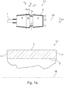
- FIG.1a A tubular cage blank 1.1 is shown, which is formed from a conventional cage material and which has a first, inner and a second, outer peripheral edge 2, 3. Furthermore, the cage blank 1.1 is laterally delimited by a first edge 4 and a second edge 5.
- This cage blank is solidly made of metal or another cage material, such as plastic.
- a milling cutter 6.1 Above the cage blank 1 there is a milling cutter 6.1, which has a drive shaft 7, a first cone 8, a second cone 9, a first cylinder 10 and a second cylinder 11. The first cone 8 axially adjoins the drive shaft 7 with its small diameter side.
- the large diameter side of the first cone 8 merges into the first cylinder 10, the diameter D1 of the first cylinder 10 and the diameter D2 on the large diameter side of the first cone 8 being the same size.
- the side of the first cylinder 10, which faces away from the large diameter side of the first cone 8, is adjoined by the second cylinder 11, which has a smaller diameter D3 than the diameter D1 of the first cylinder 10.
- the second cone 9, which has the same dimensions as the first cone 8, directly adjoins the second cylinder 11 with its large diameter side.
- the diameters of the small diameter sides of the two cones are denoted by D4.
- Both the drive shaft 7, the two cones 8, 9 and also the two cylinders 10, 11 are arranged centrally to the axis of rotation DA shown.
- the axial length L1 of the first cylinder 10 is equal to the axial length L2 of the second cylinder 10.
- the thick solid lines in Fig. 1a and b it is indicated that the lateral surfaces of the milling cutter 6.1 marked in this way are designed as cutting surfaces S.
- the small end face of the first cone 8 and the ring edge on the large end face of the second cone 9 on the large diameter side can also be designed as cutting faces S.
- the milling cutter 6.1 is lowered in the direction of arrow P1 onto the cage blank 1.1 in the direction of its central axis M, material of the cage blank 1.1 is milled away and the Fig. 1b shown ratios. It is essential in the radial movement of the milling cutter 6.1 against the cage blank 1.1 that the axis of rotation DA assumes a position at the end of the radial movement that lies between the inner peripheral edge 2 and the outer peripheral edge 3. In the embodiment according to Fig. 1b this is realized in such a way that the axis of rotation DA of the milling cutter 6.1 is at a substantially smaller distance from the inner peripheral edge 2 than from the outer peripheral edge 3. Fig.
- Fig. 1b shows a section according to BB Fig. 1c shows.
- Fig. 3c which have a section CC according Fig. 1d shows, it can be seen that the radial movement of the milling cutter 6.1 in the direction of arrow P1 ( Fig.1a ) in the first edge 4 of the cage blank 1.1 from the drive shaft 7, which, as already in connection with Fig. 1a explained, is provided on its outer surface with a cutting structure S, a cut 15 is introduced, the width B of which is narrower than the diameter D4 of the small diameter side of the first cone 8.
- This provides lateral tabs 16 which ensure that pockets 14 are formed in the pockets 14 inserted rolling elements (not shown) cannot emerge from the pockets 14 in the direction of the arrow P3.
- FIG. 2 The embodiment, which in Fig. 2 shown differs from that together with the 1a to d shown embodiment in that the cutter 6.1 penetrates far less deep radially into the cage blank 1.1.
- the milling cutter 6.1 accordingly Fig. 1b Moving in the direction of arrow P2 against the second edge 5, the overlap Ü on the second cone 9 causes an undercut-free design with a view of FIG Fig. 2 right part of the pocket 14.
- the lower penetration depth T of the milling cutter 6.1 also has the effect that, in comparison to the exemplary embodiment according to FIGS 1a to d a much larger contact surface 17 located below the axis of rotation DA is made available ( Fig. 3d ) with which - as is usual with a rolling element-guided cage - the cage runs against the rolling elements and is guided by them.
- Fig. 3b shown also formed in the embodiment according to Fig.
- Fig. 3d is a view into a pocket 14 formed without milling cutter 6.1 according to the section DD according Fig. 2 the subject.
- Fig. 3e which have a section EE Fig. 2 shows, can be removed, are provided by the radial movement in the direction of arrow P1 not only on the first edge 4 of the cage blank 1.1 rag 16. Rather, remains in accordance with the in the embodiment Fig.
- a smaller penetration depth T of the milling cutter 6.1 into the cage blank 1.1 on the inner circumferential edge of the edge 4 has a bridging 18 to which the inner circumferential edge 2 remains connected overall despite the introduction of pockets 14.
- These bridges 18 ensure that the cage blank 1.1 formed in this way cannot expand in the circumferential direction when it is used in a rolling bearing for guiding rolling bodies.
- the cage blank 1.2 can also have pre-formed pockets 14 ', which are compared to the finished ones Bags 14 are slightly smaller.
- Such pre-formed pockets 14 ' can be made available, for example, by producing the cage blank 1.2 as a cast part together with the pre-formed pockets 14'. As can be easily seen, pre-formed pockets 14 'significantly reduce the milling work.
- FIG. 5 A further milling cutter 6.2 is shown for executing the method, the lateral surface of the two cones 8, 9 not having a straight, but a curved course in the axial direction, as in the previous exemplary embodiments. Also in another embodiment (not shown) in a milling cutter 6.1 1a-c or Fig. 2 the transitions between the cones 8, 9 to the cylinders 10, 11 and the transitions between the two cylinders 10, 11 are rounded.
- Fig. 6 shows a double-row spherical roller bearing 19, in which 20 spherical rolling elements 21 are arranged between outboard bearing rings and are guided by a roller bearing cage 22 produced according to the invention, which according to the embodiment according to 1a to d was produced.
- This representation clearly shows that axially extending webs 23 extend from the second edge 5 of this roller bearing cage 22. Characterized in that this roller bearing cage 22 according to the embodiment corresponding to the 1a to d was formed, the millings 15 cut through the first edge 4 completely, so that the rolling elements 21 on the first edge 4 are secured only by the tabs 16.
Applications Claiming Priority (1)
| Application Number | Priority Date | Filing Date | Title |
|---|---|---|---|
| DE102018129894.3A DE102018129894A1 (de) | 2018-11-27 | 2018-11-27 | Verfahren zur Herstellung eines Pendelrollenlagerkäfigs und eines nach dem Verfahren hergestellten Wälzlagerkäfig |
Publications (2)
| Publication Number | Publication Date |
|---|---|
| EP3660344A1 true EP3660344A1 (fr) | 2020-06-03 |
| EP3660344B1 EP3660344B1 (fr) | 2021-06-30 |
Family
ID=68655374
Family Applications (1)
| Application Number | Title | Priority Date | Filing Date |
|---|---|---|---|
| EP19211208.4A Active EP3660344B1 (fr) | 2018-11-27 | 2019-11-25 | Procede de production d'une cage de roulement a rouleaux spheriques et cage de roulement produite selon ce procede |
Country Status (2)
| Country | Link |
|---|---|
| EP (1) | EP3660344B1 (fr) |
| DE (1) | DE102018129894A1 (fr) |
Families Citing this family (1)
| Publication number | Priority date | Publication date | Assignee | Title |
|---|---|---|---|---|
| DE102022109860B3 (de) | 2022-04-25 | 2023-01-12 | Ringspann Gmbh | Käfigfreilauf mit lagerrollen |
Citations (2)
| Publication number | Priority date | Publication date | Assignee | Title |
|---|---|---|---|---|
| US3290102A (en) * | 1960-03-05 | 1966-12-06 | Skf Svenska Kullagerfab Ab | Spherical roller bearing with barrel-shaped rollers |
| DE102016202919A1 (de) * | 2016-02-25 | 2017-08-31 | Schaeffler Technologies AG & Co. KG | Pendelrollenlager |
Family Cites Families (7)
| Publication number | Priority date | Publication date | Assignee | Title |
|---|---|---|---|---|
| GB2242147B (en) * | 1990-03-22 | 1993-07-28 | Skf Gmbh | A device for forming pockets in cages |
| DE4009171A1 (de) * | 1990-03-22 | 1991-09-26 | Skf Gmbh | Vorrichtung zum spannen von rohrfoermigen zwischenprodukten |
| DE4228322A1 (de) * | 1992-08-26 | 1994-03-03 | Guenther Wirth | Bohrfräser |
| EP1816362A4 (fr) * | 2004-11-24 | 2009-05-06 | Nsk Ltd | Roulement a rotule sur rouleaux muni d'un dispositif de retenue et procede de fabrication du dispositif de retenue pour le roulement a rotule sur rouleaux |
| JP2006266277A (ja) * | 2005-03-22 | 2006-10-05 | Nsk Ltd | 保持器付自動調心ころ軸受 |
| DE102010020019B4 (de) * | 2010-05-10 | 2012-05-31 | Gebr. Reinfurt Gmbh & Co. Kg | Verfahren zum Herstellen eines kugelgeführten Schnappkäfigs aus Kunststoffmaterial |
| JP2012002306A (ja) * | 2010-06-18 | 2012-01-05 | Ntn Corp | 自動調心ころ軸受の保持器及び自動調心ころ軸受の組立方法 |
-
2018
- 2018-11-27 DE DE102018129894.3A patent/DE102018129894A1/de not_active Withdrawn
-
2019
- 2019-11-25 EP EP19211208.4A patent/EP3660344B1/fr active Active
Patent Citations (2)
| Publication number | Priority date | Publication date | Assignee | Title |
|---|---|---|---|---|
| US3290102A (en) * | 1960-03-05 | 1966-12-06 | Skf Svenska Kullagerfab Ab | Spherical roller bearing with barrel-shaped rollers |
| DE102016202919A1 (de) * | 2016-02-25 | 2017-08-31 | Schaeffler Technologies AG & Co. KG | Pendelrollenlager |
Also Published As
| Publication number | Publication date |
|---|---|
| DE102018129894A1 (de) | 2020-05-28 |
| EP3660344B1 (fr) | 2021-06-30 |
Similar Documents
| Publication | Publication Date | Title |
|---|---|---|
| DE102011112148B4 (de) | Extruder und Verfahren zum Herstellen eines Extruders | |
| DE112011101552B4 (de) | Axialkäfig für zylindrische Wälzkörper | |
| DE102010022512B4 (de) | Gleitlager für Verbrennungsmotor | |
| DE19654584B4 (de) | Käfig für Nadellager und Verfahren zu dessen Herstellung | |
| DE10107109A1 (de) | Bundbuchse, Verfahren zu ihrer Herstellung und Biegewerkzeug zur Herstellung von Bunden an einer Buchse | |
| DE102011003211A1 (de) | Wälzlager | |
| DE112015004960T5 (de) | Kegelrollenlager | |
| EP2893207B1 (fr) | Cage axiale pour corps de roulement cylindriques | |
| DE112015004932T5 (de) | Kegelrollenlager | |
| EP3660344B1 (fr) | Procede de production d'une cage de roulement a rouleaux spheriques et cage de roulement produite selon ce procede | |
| DE102011087444A1 (de) | Verfahren zum Herstellen eines Lagerbauteiles, Lagerbauteil sowie Pendelrollenlager | |
| DE19936014A1 (de) | Gummilager mit axialer Dämpfung | |
| DE112015004945T5 (de) | Kegelrollenlager | |
| WO2008074560A2 (fr) | Procédé de fabrication d'un anneau de synchronisation d'un dispositif de synchronisation | |
| DE2014420B2 (de) | Kafigring fur Walzlager und Verfahren zu dessen Herstellung | |
| DE112015004946T5 (de) | Kegelrollenlager | |
| DE102018101551A1 (de) | Käfig für ein Wälzlager, Verfahren zum Fertigen des Käfigs sowie ein Käfigrohling | |
| DE965459C (de) | Nadelrollenkaefig | |
| DE102020121239A1 (de) | Verfahren zur Herstellung einer Schiebemuffe für eine Synchronisierungseinheit, Schiebemuffe sowie Synchronisierungseinheit | |
| DE102008050231A1 (de) | Wälzkörper | |
| DE102009050524A1 (de) | Radial-Rollenwälzlager | |
| WO2007088144A2 (fr) | Palier à bagues minces | |
| DE19517217C2 (de) | Massivfensterkäfig für ein Nadellager | |
| DE102004055227A1 (de) | Kegelrollenlager | |
| DE102018128075B4 (de) | Verfahren zum Ausbilden einer Laufbahnüberhöhung an einem Lagerring, einem Kupplungsausrücklager hergestellt nach dem Verfahren und einen Werkzeugsatz |
Legal Events
| Date | Code | Title | Description |
|---|---|---|---|
| PUAI | Public reference made under article 153(3) epc to a published international application that has entered the european phase |
Free format text: ORIGINAL CODE: 0009012 |
|
| STAA | Information on the status of an ep patent application or granted ep patent |
Free format text: STATUS: THE APPLICATION HAS BEEN PUBLISHED |
|
| AK | Designated contracting states |
Kind code of ref document: A1 Designated state(s): AL AT BE BG CH CY CZ DE DK EE ES FI FR GB GR HR HU IE IS IT LI LT LU LV MC MK MT NL NO PL PT RO RS SE SI SK SM TR |
|
| AX | Request for extension of the european patent |
Extension state: BA ME |
|
| STAA | Information on the status of an ep patent application or granted ep patent |
Free format text: STATUS: REQUEST FOR EXAMINATION WAS MADE |
|
| 17P | Request for examination filed |
Effective date: 20201203 |
|
| RBV | Designated contracting states (corrected) |
Designated state(s): AL AT BE BG CH CY CZ DE DK EE ES FI FR GB GR HR HU IE IS IT LI LT LU LV MC MK MT NL NO PL PT RO RS SE SI SK SM TR |
|
| GRAP | Despatch of communication of intention to grant a patent |
Free format text: ORIGINAL CODE: EPIDOSNIGR1 |
|
| STAA | Information on the status of an ep patent application or granted ep patent |
Free format text: STATUS: GRANT OF PATENT IS INTENDED |
|
| INTG | Intention to grant announced |
Effective date: 20210315 |
|
| GRAS | Grant fee paid |
Free format text: ORIGINAL CODE: EPIDOSNIGR3 |
|
| GRAA | (expected) grant |
Free format text: ORIGINAL CODE: 0009210 |
|
| STAA | Information on the status of an ep patent application or granted ep patent |
Free format text: STATUS: THE PATENT HAS BEEN GRANTED |
|
| AK | Designated contracting states |
Kind code of ref document: B1 Designated state(s): AL AT BE BG CH CY CZ DE DK EE ES FI FR GB GR HR HU IE IS IT LI LT LU LV MC MK MT NL NO PL PT RO RS SE SI SK SM TR |
|
| REG | Reference to a national code |
Ref country code: CH Ref legal event code: EP |
|
| REG | Reference to a national code |
Ref country code: AT Ref legal event code: REF Ref document number: 1406608 Country of ref document: AT Kind code of ref document: T Effective date: 20210715 |
|
| REG | Reference to a national code |
Ref country code: DE Ref legal event code: R096 Ref document number: 502019001723 Country of ref document: DE |
|
| REG | Reference to a national code |
Ref country code: IE Ref legal event code: FG4D Free format text: LANGUAGE OF EP DOCUMENT: GERMAN |
|
| REG | Reference to a national code |
Ref country code: RO Ref legal event code: EPE |
|
| REG | Reference to a national code |
Ref country code: SE Ref legal event code: TRGR |
|
| REG | Reference to a national code |
Ref country code: LT Ref legal event code: MG9D |
|
| PG25 | Lapsed in a contracting state [announced via postgrant information from national office to epo] |
Ref country code: BG Free format text: LAPSE BECAUSE OF FAILURE TO SUBMIT A TRANSLATION OF THE DESCRIPTION OR TO PAY THE FEE WITHIN THE PRESCRIBED TIME-LIMIT Effective date: 20210930 Ref country code: FI Free format text: LAPSE BECAUSE OF FAILURE TO SUBMIT A TRANSLATION OF THE DESCRIPTION OR TO PAY THE FEE WITHIN THE PRESCRIBED TIME-LIMIT Effective date: 20210630 Ref country code: HR Free format text: LAPSE BECAUSE OF FAILURE TO SUBMIT A TRANSLATION OF THE DESCRIPTION OR TO PAY THE FEE WITHIN THE PRESCRIBED TIME-LIMIT Effective date: 20210630 |
|
| REG | Reference to a national code |
Ref country code: NL Ref legal event code: MP Effective date: 20210630 |
|
| PG25 | Lapsed in a contracting state [announced via postgrant information from national office to epo] |
Ref country code: GR Free format text: LAPSE BECAUSE OF FAILURE TO SUBMIT A TRANSLATION OF THE DESCRIPTION OR TO PAY THE FEE WITHIN THE PRESCRIBED TIME-LIMIT Effective date: 20211001 Ref country code: RS Free format text: LAPSE BECAUSE OF FAILURE TO SUBMIT A TRANSLATION OF THE DESCRIPTION OR TO PAY THE FEE WITHIN THE PRESCRIBED TIME-LIMIT Effective date: 20210630 Ref country code: LV Free format text: LAPSE BECAUSE OF FAILURE TO SUBMIT A TRANSLATION OF THE DESCRIPTION OR TO PAY THE FEE WITHIN THE PRESCRIBED TIME-LIMIT Effective date: 20210630 Ref country code: NO Free format text: LAPSE BECAUSE OF FAILURE TO SUBMIT A TRANSLATION OF THE DESCRIPTION OR TO PAY THE FEE WITHIN THE PRESCRIBED TIME-LIMIT Effective date: 20210930 |
|
| PG25 | Lapsed in a contracting state [announced via postgrant information from national office to epo] |
Ref country code: CZ Free format text: LAPSE BECAUSE OF FAILURE TO SUBMIT A TRANSLATION OF THE DESCRIPTION OR TO PAY THE FEE WITHIN THE PRESCRIBED TIME-LIMIT Effective date: 20210630 Ref country code: SM Free format text: LAPSE BECAUSE OF FAILURE TO SUBMIT A TRANSLATION OF THE DESCRIPTION OR TO PAY THE FEE WITHIN THE PRESCRIBED TIME-LIMIT Effective date: 20210630 Ref country code: PT Free format text: LAPSE BECAUSE OF FAILURE TO SUBMIT A TRANSLATION OF THE DESCRIPTION OR TO PAY THE FEE WITHIN THE PRESCRIBED TIME-LIMIT Effective date: 20211102 Ref country code: NL Free format text: LAPSE BECAUSE OF FAILURE TO SUBMIT A TRANSLATION OF THE DESCRIPTION OR TO PAY THE FEE WITHIN THE PRESCRIBED TIME-LIMIT Effective date: 20210630 Ref country code: SK Free format text: LAPSE BECAUSE OF FAILURE TO SUBMIT A TRANSLATION OF THE DESCRIPTION OR TO PAY THE FEE WITHIN THE PRESCRIBED TIME-LIMIT Effective date: 20210630 Ref country code: ES Free format text: LAPSE BECAUSE OF FAILURE TO SUBMIT A TRANSLATION OF THE DESCRIPTION OR TO PAY THE FEE WITHIN THE PRESCRIBED TIME-LIMIT Effective date: 20210630 Ref country code: EE Free format text: LAPSE BECAUSE OF FAILURE TO SUBMIT A TRANSLATION OF THE DESCRIPTION OR TO PAY THE FEE WITHIN THE PRESCRIBED TIME-LIMIT Effective date: 20210630 |
|
| PG25 | Lapsed in a contracting state [announced via postgrant information from national office to epo] |
Ref country code: PL Free format text: LAPSE BECAUSE OF FAILURE TO SUBMIT A TRANSLATION OF THE DESCRIPTION OR TO PAY THE FEE WITHIN THE PRESCRIBED TIME-LIMIT Effective date: 20210630 |
|
| REG | Reference to a national code |
Ref country code: DE Ref legal event code: R097 Ref document number: 502019001723 Country of ref document: DE |
|
| PG25 | Lapsed in a contracting state [announced via postgrant information from national office to epo] |
Ref country code: DK Free format text: LAPSE BECAUSE OF FAILURE TO SUBMIT A TRANSLATION OF THE DESCRIPTION OR TO PAY THE FEE WITHIN THE PRESCRIBED TIME-LIMIT Effective date: 20210630 |
|
| PLBE | No opposition filed within time limit |
Free format text: ORIGINAL CODE: 0009261 |
|
| STAA | Information on the status of an ep patent application or granted ep patent |
Free format text: STATUS: NO OPPOSITION FILED WITHIN TIME LIMIT |
|
| PG25 | Lapsed in a contracting state [announced via postgrant information from national office to epo] |
Ref country code: AL Free format text: LAPSE BECAUSE OF FAILURE TO SUBMIT A TRANSLATION OF THE DESCRIPTION OR TO PAY THE FEE WITHIN THE PRESCRIBED TIME-LIMIT Effective date: 20210630 |
|
| REG | Reference to a national code |
Ref country code: DE Ref legal event code: R119 Ref document number: 502019001723 Country of ref document: DE |
|
| 26N | No opposition filed |
Effective date: 20220331 |
|
| PG25 | Lapsed in a contracting state [announced via postgrant information from national office to epo] |
Ref country code: MC Free format text: LAPSE BECAUSE OF FAILURE TO SUBMIT A TRANSLATION OF THE DESCRIPTION OR TO PAY THE FEE WITHIN THE PRESCRIBED TIME-LIMIT Effective date: 20210630 |
|
| PG25 | Lapsed in a contracting state [announced via postgrant information from national office to epo] |
Ref country code: LU Free format text: LAPSE BECAUSE OF NON-PAYMENT OF DUE FEES Effective date: 20211125 Ref country code: BE Free format text: LAPSE BECAUSE OF NON-PAYMENT OF DUE FEES Effective date: 20211130 |
|
| REG | Reference to a national code |
Ref country code: BE Ref legal event code: MM Effective date: 20211130 |
|
| PG25 | Lapsed in a contracting state [announced via postgrant information from national office to epo] |
Ref country code: IE Free format text: LAPSE BECAUSE OF NON-PAYMENT OF DUE FEES Effective date: 20211125 Ref country code: DE Free format text: LAPSE BECAUSE OF NON-PAYMENT OF DUE FEES Effective date: 20220601 |
|
| PG25 | Lapsed in a contracting state [announced via postgrant information from national office to epo] |
Ref country code: LT Free format text: LAPSE BECAUSE OF FAILURE TO SUBMIT A TRANSLATION OF THE DESCRIPTION OR TO PAY THE FEE WITHIN THE PRESCRIBED TIME-LIMIT Effective date: 20210630 |
|
| P01 | Opt-out of the competence of the unified patent court (upc) registered |
Effective date: 20230522 |
|
| PG25 | Lapsed in a contracting state [announced via postgrant information from national office to epo] |
Ref country code: CY Free format text: LAPSE BECAUSE OF FAILURE TO SUBMIT A TRANSLATION OF THE DESCRIPTION OR TO PAY THE FEE WITHIN THE PRESCRIBED TIME-LIMIT Effective date: 20210630 |
|
| REG | Reference to a national code |
Ref country code: CH Ref legal event code: PL |
|
| PG25 | Lapsed in a contracting state [announced via postgrant information from national office to epo] |
Ref country code: LI Free format text: LAPSE BECAUSE OF NON-PAYMENT OF DUE FEES Effective date: 20221130 Ref country code: HU Free format text: LAPSE BECAUSE OF FAILURE TO SUBMIT A TRANSLATION OF THE DESCRIPTION OR TO PAY THE FEE WITHIN THE PRESCRIBED TIME-LIMIT; INVALID AB INITIO Effective date: 20191125 Ref country code: CH Free format text: LAPSE BECAUSE OF NON-PAYMENT OF DUE FEES Effective date: 20221130 |
|
| PGFP | Annual fee paid to national office [announced via postgrant information from national office to epo] |
Ref country code: SE Payment date: 20231120 Year of fee payment: 5 Ref country code: RO Payment date: 20231116 Year of fee payment: 5 Ref country code: IT Payment date: 20231124 Year of fee payment: 5 Ref country code: FR Payment date: 20231120 Year of fee payment: 5 |