EP3659830B1 - Procédé d'identification de positions de modules de roue - Google Patents
Procédé d'identification de positions de modules de roue Download PDFInfo
- Publication number
- EP3659830B1 EP3659830B1 EP18215403.9A EP18215403A EP3659830B1 EP 3659830 B1 EP3659830 B1 EP 3659830B1 EP 18215403 A EP18215403 A EP 18215403A EP 3659830 B1 EP3659830 B1 EP 3659830B1
- Authority
- EP
- European Patent Office
- Prior art keywords
- wheel
- vehicle
- modules
- tyre
- module
- Prior art date
- Legal status (The legal status is an assumption and is not a legal conclusion. Google has not performed a legal analysis and makes no representation as to the accuracy of the status listed.)
- Active
Links
- 238000000034 method Methods 0.000 title claims description 71
- 230000001133 acceleration Effects 0.000 claims description 111
- 238000012544 monitoring process Methods 0.000 claims description 71
- 238000012545 processing Methods 0.000 claims description 58
- 230000006854 communication Effects 0.000 claims description 35
- 238000004891 communication Methods 0.000 claims description 35
- 238000012423 maintenance Methods 0.000 claims description 30
- 238000004458 analytical method Methods 0.000 claims description 24
- 230000008439 repair process Effects 0.000 claims description 11
- 230000008569 process Effects 0.000 claims description 8
- 230000002123 temporal effect Effects 0.000 claims description 6
- 230000002093 peripheral effect Effects 0.000 claims description 5
- 230000009471 action Effects 0.000 claims description 2
- 238000002360 preparation method Methods 0.000 claims description 2
- 230000006870 function Effects 0.000 description 37
- 230000000875 corresponding effect Effects 0.000 description 31
- 230000008859 change Effects 0.000 description 26
- 230000004044 response Effects 0.000 description 15
- 230000009286 beneficial effect Effects 0.000 description 13
- 238000005259 measurement Methods 0.000 description 13
- 230000005855 radiation Effects 0.000 description 10
- 230000007547 defect Effects 0.000 description 8
- 230000001419 dependent effect Effects 0.000 description 8
- 230000008901 benefit Effects 0.000 description 7
- 230000000694 effects Effects 0.000 description 7
- 239000010408 film Substances 0.000 description 7
- 238000002485 combustion reaction Methods 0.000 description 6
- 238000010586 diagram Methods 0.000 description 6
- 239000000446 fuel Substances 0.000 description 6
- 230000007257 malfunction Effects 0.000 description 6
- 230000002950 deficient Effects 0.000 description 5
- 230000005484 gravity Effects 0.000 description 5
- 239000002184 metal Substances 0.000 description 5
- 230000002829 reductive effect Effects 0.000 description 5
- 238000000926 separation method Methods 0.000 description 5
- 239000000725 suspension Substances 0.000 description 5
- XUIMIQQOPSSXEZ-UHFFFAOYSA-N Silicon Chemical compound [Si] XUIMIQQOPSSXEZ-UHFFFAOYSA-N 0.000 description 4
- 230000002411 adverse Effects 0.000 description 4
- 230000015556 catabolic process Effects 0.000 description 4
- 229920001971 elastomer Polymers 0.000 description 4
- 238000007726 management method Methods 0.000 description 4
- 239000000463 material Substances 0.000 description 4
- 239000005060 rubber Substances 0.000 description 4
- 229910052710 silicon Inorganic materials 0.000 description 4
- 239000010703 silicon Substances 0.000 description 4
- 238000003860 storage Methods 0.000 description 4
- 238000005482 strain hardening Methods 0.000 description 4
- 238000013528 artificial neural network Methods 0.000 description 3
- 230000002596 correlated effect Effects 0.000 description 3
- 230000007423 decrease Effects 0.000 description 3
- 230000000881 depressing effect Effects 0.000 description 3
- 238000009795 derivation Methods 0.000 description 3
- 230000002708 enhancing effect Effects 0.000 description 3
- 238000004519 manufacturing process Methods 0.000 description 3
- 239000013307 optical fiber Substances 0.000 description 3
- 230000021715 photosynthesis, light harvesting Effects 0.000 description 3
- 230000000754 repressing effect Effects 0.000 description 3
- 238000005070 sampling Methods 0.000 description 3
- 239000010409 thin film Substances 0.000 description 3
- 238000009423 ventilation Methods 0.000 description 3
- CURLTUGMZLYLDI-UHFFFAOYSA-N Carbon dioxide Chemical compound O=C=O CURLTUGMZLYLDI-UHFFFAOYSA-N 0.000 description 2
- 229910000831 Steel Inorganic materials 0.000 description 2
- 230000003213 activating effect Effects 0.000 description 2
- 238000013459 approach Methods 0.000 description 2
- 230000000712 assembly Effects 0.000 description 2
- 238000000429 assembly Methods 0.000 description 2
- 238000001816 cooling Methods 0.000 description 2
- 238000006731 degradation reaction Methods 0.000 description 2
- 238000005516 engineering process Methods 0.000 description 2
- 238000011156 evaluation Methods 0.000 description 2
- 239000000835 fiber Substances 0.000 description 2
- 239000012530 fluid Substances 0.000 description 2
- 238000007429 general method Methods 0.000 description 2
- 238000013507 mapping Methods 0.000 description 2
- 238000012986 modification Methods 0.000 description 2
- 230000003287 optical effect Effects 0.000 description 2
- 230000036961 partial effect Effects 0.000 description 2
- 230000000737 periodic effect Effects 0.000 description 2
- 239000004033 plastic Substances 0.000 description 2
- 229920003023 plastic Polymers 0.000 description 2
- 238000005096 rolling process Methods 0.000 description 2
- 239000010959 steel Substances 0.000 description 2
- 238000012384 transportation and delivery Methods 0.000 description 2
- 210000000707 wrist Anatomy 0.000 description 2
- OKTJSMMVPCPJKN-UHFFFAOYSA-N Carbon Chemical compound [C] OKTJSMMVPCPJKN-UHFFFAOYSA-N 0.000 description 1
- 230000005355 Hall effect Effects 0.000 description 1
- 235000015842 Hesperis Nutrition 0.000 description 1
- 244000043261 Hevea brasiliensis Species 0.000 description 1
- 235000012633 Iberis amara Nutrition 0.000 description 1
- 235000014676 Phragmites communis Nutrition 0.000 description 1
- 208000027418 Wounds and injury Diseases 0.000 description 1
- 230000004913 activation Effects 0.000 description 1
- 238000013475 authorization Methods 0.000 description 1
- 230000007175 bidirectional communication Effects 0.000 description 1
- 230000005540 biological transmission Effects 0.000 description 1
- 230000015572 biosynthetic process Effects 0.000 description 1
- 239000007767 bonding agent Substances 0.000 description 1
- 239000011469 building brick Substances 0.000 description 1
- 229910052799 carbon Inorganic materials 0.000 description 1
- 229910002092 carbon dioxide Inorganic materials 0.000 description 1
- 239000001569 carbon dioxide Substances 0.000 description 1
- 239000000969 carrier Substances 0.000 description 1
- 230000000295 complement effect Effects 0.000 description 1
- 238000010276 construction Methods 0.000 description 1
- 238000012937 correction Methods 0.000 description 1
- 230000006378 damage Effects 0.000 description 1
- 238000013144 data compression Methods 0.000 description 1
- 238000013479 data entry Methods 0.000 description 1
- 238000013523 data management Methods 0.000 description 1
- 230000003111 delayed effect Effects 0.000 description 1
- 238000013461 design Methods 0.000 description 1
- 238000001514 detection method Methods 0.000 description 1
- 230000005489 elastic deformation Effects 0.000 description 1
- 230000005611 electricity Effects 0.000 description 1
- 238000005265 energy consumption Methods 0.000 description 1
- 230000001747 exhibiting effect Effects 0.000 description 1
- 230000002349 favourable effect Effects 0.000 description 1
- 230000014509 gene expression Effects 0.000 description 1
- 238000010438 heat treatment Methods 0.000 description 1
- 230000003116 impacting effect Effects 0.000 description 1
- 230000006872 improvement Effects 0.000 description 1
- 208000014674 injury Diseases 0.000 description 1
- 238000007689 inspection Methods 0.000 description 1
- 238000009434 installation Methods 0.000 description 1
- 239000011810 insulating material Substances 0.000 description 1
- 230000010354 integration Effects 0.000 description 1
- 238000002955 isolation Methods 0.000 description 1
- 230000000670 limiting effect Effects 0.000 description 1
- 230000014759 maintenance of location Effects 0.000 description 1
- 239000011159 matrix material Substances 0.000 description 1
- 239000012528 membrane Substances 0.000 description 1
- 238000004377 microelectronic Methods 0.000 description 1
- 238000005459 micromachining Methods 0.000 description 1
- 230000004048 modification Effects 0.000 description 1
- 238000012806 monitoring device Methods 0.000 description 1
- 238000000465 moulding Methods 0.000 description 1
- 229920003052 natural elastomer Polymers 0.000 description 1
- 229920001194 natural rubber Polymers 0.000 description 1
- 230000006855 networking Effects 0.000 description 1
- 238000010606 normalization Methods 0.000 description 1
- 230000003534 oscillatory effect Effects 0.000 description 1
- 230000000149 penetrating effect Effects 0.000 description 1
- 229920003223 poly(pyromellitimide-1,4-diphenyl ether) Polymers 0.000 description 1
- 230000000644 propagated effect Effects 0.000 description 1
- 230000001681 protective effect Effects 0.000 description 1
- 230000009467 reduction Effects 0.000 description 1
- 238000009877 rendering Methods 0.000 description 1
- 230000003252 repetitive effect Effects 0.000 description 1
- 230000000717 retained effect Effects 0.000 description 1
- 230000002441 reversible effect Effects 0.000 description 1
- 238000007493 shaping process Methods 0.000 description 1
- 230000035939 shock Effects 0.000 description 1
- 238000004088 simulation Methods 0.000 description 1
- 239000004575 stone Substances 0.000 description 1
- 239000000126 substance Substances 0.000 description 1
- 230000001360 synchronised effect Effects 0.000 description 1
- 238000003786 synthesis reaction Methods 0.000 description 1
- 229920003051 synthetic elastomer Polymers 0.000 description 1
- 239000005061 synthetic rubber Substances 0.000 description 1
- 238000012876 topography Methods 0.000 description 1
- 238000011179 visual inspection Methods 0.000 description 1
- XLYOFNOQVPJJNP-UHFFFAOYSA-N water Substances O XLYOFNOQVPJJNP-UHFFFAOYSA-N 0.000 description 1
- 238000005303 weighing Methods 0.000 description 1
Images


Classifications
-
- B—PERFORMING OPERATIONS; TRANSPORTING
- B60—VEHICLES IN GENERAL
- B60C—VEHICLE TYRES; TYRE INFLATION; TYRE CHANGING; CONNECTING VALVES TO INFLATABLE ELASTIC BODIES IN GENERAL; DEVICES OR ARRANGEMENTS RELATED TO TYRES
- B60C23/00—Devices for measuring, signalling, controlling, or distributing tyre pressure or temperature, specially adapted for mounting on vehicles; Arrangement of tyre inflating devices on vehicles, e.g. of pumps or of tanks; Tyre cooling arrangements
- B60C23/02—Signalling devices actuated by tyre pressure
- B60C23/04—Signalling devices actuated by tyre pressure mounted on the wheel or tyre
- B60C23/0408—Signalling devices actuated by tyre pressure mounted on the wheel or tyre transmitting the signals by non-mechanical means from the wheel or tyre to a vehicle body mounted receiver
- B60C23/0415—Automatically identifying wheel mounted units, e.g. after replacement or exchange of wheels
- B60C23/0416—Automatically identifying wheel mounted units, e.g. after replacement or exchange of wheels allocating a corresponding wheel position on vehicle, e.g. front/left or rear/right
-
- B—PERFORMING OPERATIONS; TRANSPORTING
- B60—VEHICLES IN GENERAL
- B60C—VEHICLE TYRES; TYRE INFLATION; TYRE CHANGING; CONNECTING VALVES TO INFLATABLE ELASTIC BODIES IN GENERAL; DEVICES OR ARRANGEMENTS RELATED TO TYRES
- B60C23/00—Devices for measuring, signalling, controlling, or distributing tyre pressure or temperature, specially adapted for mounting on vehicles; Arrangement of tyre inflating devices on vehicles, e.g. of pumps or of tanks; Tyre cooling arrangements
- B60C23/02—Signalling devices actuated by tyre pressure
- B60C23/04—Signalling devices actuated by tyre pressure mounted on the wheel or tyre
- B60C23/0408—Signalling devices actuated by tyre pressure mounted on the wheel or tyre transmitting the signals by non-mechanical means from the wheel or tyre to a vehicle body mounted receiver
- B60C23/0471—System initialisation, e.g. upload or calibration of operating parameters
-
- B—PERFORMING OPERATIONS; TRANSPORTING
- B60—VEHICLES IN GENERAL
- B60C—VEHICLE TYRES; TYRE INFLATION; TYRE CHANGING; CONNECTING VALVES TO INFLATABLE ELASTIC BODIES IN GENERAL; DEVICES OR ARRANGEMENTS RELATED TO TYRES
- B60C23/00—Devices for measuring, signalling, controlling, or distributing tyre pressure or temperature, specially adapted for mounting on vehicles; Arrangement of tyre inflating devices on vehicles, e.g. of pumps or of tanks; Tyre cooling arrangements
- B60C23/02—Signalling devices actuated by tyre pressure
- B60C23/04—Signalling devices actuated by tyre pressure mounted on the wheel or tyre
- B60C23/0486—Signalling devices actuated by tyre pressure mounted on the wheel or tyre comprising additional sensors in the wheel or tyre mounted monitoring device, e.g. movement sensors, microphones or earth magnetic field sensors
- B60C23/0488—Movement sensor, e.g. for sensing angular speed, acceleration or centripetal force
-
- G—PHYSICS
- G01—MEASURING; TESTING
- G01M—TESTING STATIC OR DYNAMIC BALANCE OF MACHINES OR STRUCTURES; TESTING OF STRUCTURES OR APPARATUS, NOT OTHERWISE PROVIDED FOR
- G01M17/00—Testing of vehicles
- G01M17/007—Wheeled or endless-tracked vehicles
- G01M17/013—Wheels
Definitions
- the present invention relates to methods of identifying positions of wheel modules included in wheels and/or their associated tyres; for example, to a method of identifying positions of wheel modules operable to monitor characteristics of wheels and/or their associated tyres and conveying information indicative of these aforementioned characteristics via a communication link to an electronic control unit (ECU) and/or control system, for example for user-display.
- ECU electronice control unit
- the present invention also concerns a wheel monitoring apparatus.
- the invention relates to methods of servicing vehicles including such a wheel monitoring apparatus.
- Tyres also known as "tires" in American-English, are critical components in road vehicles. Contemporary tyres not only ensure adhesion of their associated road vehicles to road surfaces in widely varying weather conditions, but also perform vibration and shock isolation functions. Moreover, during their operating lifetime, tyres are required to survive potentially up to several thousand or even millions of deformation cycles without exhibiting work-hardening failure, and yet exhibit a relatively modest degree of energy dissipation therein as a result of viscous dampening effects. As an additional operating requirement, contemporary tyres need to be robust against scuffing and objects impacting thereonto.
- tubeless tyres are required to robustly grip onto their associated wheel hubs even when subject to considerable stresses, for example during emergency braking.
- the tyres are constructed from elastic synthetic rubber, natural rubber and/or plastics material reinforced by meshes of metal wire, carbon fibre and similar. Modern tyres are therefore to be respected as highly optimized and advanced products.
- Tyre failure during operation can potentially result in immobilization of an associated vehicle or even accident.
- tyres operated at unsuitable pressures can adversely influence associated vehicle fuel economy; fuel economy is becoming increasingly pertinent in view of increases in fuel costs as well as in view of carbon dioxide generation and its perceived impact on World climate change.
- a pneumatic sensor device suitable for use with a tyre of a vehicle for detecting tyre pressure and generating corresponding tyre pressure information.
- the device includes a transmitter for transmitting the pressure information together with an identification code for distinguishing the sensor device from other such sensor devices simultaneously included on other wheels of the vehicle.
- a control unit of the vehicle is operable to receive the transmitted pressure information and its associated identification code. The received pressure information is stored in a memory of the control unit.
- the control unit is operable to raise an alarm in an event that tyre pressure is not correct pursuant to predefined criteria.
- tyre monitors are described which are mounted adjacent to tyres near their tyre inflation valve stems.
- the tyre monitors include sensors to measure pressure, temperature and rotation direction of their respective tyres.
- the monitors are operable to communicate measured sensor signals via transmitters to their respective receiver for subsequent processing and eventual presentation on a display unit.
- a vehicle mounted controller in communication with the receiver is operable to determine whether pressure information is associated with a front tyre or a rear tyre based on the strength of the wireless signal received at the receiver, and whether pressure data is associated with a right tyre or left tyre based on associated rotation direction data.
- EP 1 284 204 A1 relates to an arrangement for vehicle position assignment of the wheels of a vehicle, each wheel having means for determining the speed and direction of rotation of the respective wheel.
- a steering sensor is provided instead of the means for determining the direction of rotation of the wheel.
- an evaluation unit is provided in the vehicle which, when the vehicle is cornering, assigns a vehicle position of the individual wheels based on the speeds and directions of rotation determined for each wheel and, possibly, based on the steering direction.
- US 6 278 363 B1 relates to a method and system for monitoring air pressure or operational status of at least one particular tyre of a vehicle facilitates ready identification of a relative mounting position of the particular tyre.
- At least one pressure indicating signal is received and is associated with a particular tyre mounted at an unknown relative position on a vehicle.
- Physical parameter data are obtained indicating physical parameter measurements at the different tyres of a vehicle.
- the obtained physical parameter data are evaluated to identify the relative mounting position of the particular tyre on the vehicle. Accordingly, an operator of the vehicle may be provided with an indication that an air pressure of a particular tyre is less than a proper air pressure so that peak vehicle performance and necessary maintenance may be obtained. Even if the indication informs that the pressure is normal, the operator is reassured that the tyres are functioning properly.
- DE 101 44 360 A1 discloses that during cornering of a vehicle, wheel positions are assigned from tyre pressure measuring devices. For this purpose, it is determined by means of ABS whether it is a left-hand or right-hand curve. Wheel speeds are then measured in each tyre and sent together with identifiers to a central evaluation unit. There, the wheel speeds are related to the curve information determined by the ABS. The two higher wheel speeds are then assigned to the side of the vehicle on the outside of the curve and the two lower wheel speeds are assigned to the other side of the vehicle.
- tyre monitors are known.
- tyre monitors In order to measure tyre condition and detect unauthorized tampering with tyres, for example when wheels are temporarily removed from their associated vehicles, for example when exchange from winter tyres to summer tyres in Northern Europe and Canada, more advanced tyre and wheel monitors are required.
- tyre monitors there then arises a technical problem regarding how to manage complex configurations of tyre and wheel monitors, especially when tyres are replaced at mutually different times and wheels and their tyres are susceptible to being retained in storage over periods when exchanging between summer and winder tyres.
- the present invention seeks to address the aforementioned technical problems.
- An object of the present invention is to provide an improved method of identifying locations of wheel and/or tyre monitors included in apparatus of vehicles which is capable of enhancing safety and reliability of such vehicles.
- the physical parameter is derived from a sensor signal generated by a sensor in the module.
- the sensor may be an accelerometer arranged in each respective module, which accelerometer generates acceleration signal components in the tangential and/or radial direction ( A x , A y )
- the signals are indicative of at least one of:
- the one or more modules are mounted at one or more locations (L1, L2, L3, L4) on the at least one wheel, the one or more locations including:
- Mounting the one or more modules at these different locations is of benefit in that certain types of defect in the at least one wheel are more reliably sensed when the one or more modules are mounted at specific favourable locations. For example, wheel imbalance is better sensed with a module mounted on the wheel near its hub, whereas flexural characteristics of the tyre or inflatable cavity are better sensed with a module attached to a side wall of the tyre or flexible inflatable cavity. More optionally, a module is mounted to an inside rim of a tyre, adjacent to its treads (L4).
- the one or more modules are each provided with a corresponding identification code (ID) for communicating to the processing arrangement (ECU) so that the processing arrangement (ECU) is able to recognize from which module corresponding signal data has been sent.
- ID identification code
- Use of such identification codes (ID) enables one or more wheels which have developed problems, or have been found to have potential problems, to be clearly identified and a corresponding unambiguous informative warning sent to the driver of the vehicle and/or to a service facility responsible for addressing such problems or potential problems.
- the wheel-monitoring apparatus is optionally implemented such that the one or more modules are radially distributed around the at least one wheel for sensing operation of the at least one wheel at a plurality of angular locations therearound.
- aforesaid methods of the invention include a step of presenting information to a driver of the vehicle on a display coupled in communication with the processing arrangement (ECU), the information indicating at least one of:
- the display is however not limited to displaying such information as in (a) to (e) and is optionally capable of presenting other analysis information provided from the processing arrangement, for example a time record of changes in one or more wheel parameters as sensed by the one or more modules; for example, the display can beneficially present a graph representing tyre pressure as a function of time, a list describing a configuration of modules presently coupled in communication with the processing arrangement, and so forth.
- the processing arrangement is operable to send a message requesting the one or modules to respond back to the processing arrangement (ECU) for declaring their identification codes (ID) to the processing arrangement (ECU) for enabling the processing arrangement to identify its configuration of one or more modules, and for identifying any changes in the configuration of one or more modules occurring.
- the one or more modules are operable to also respond with data indicative of expected characteristics of the at least one wheel to which the one of more modules are mounted.
- the processing arrangement is operable to perform a correct monitoring of wheels of the vehicle, it requires a recent list or record of modules present on the wheels.
- a vehicle including a wheel-monitoring apparatus pursuant to the second aspect of the invention, the apparatus being operable to monitor operation of at least one wheel (10) of the vehicle (900) pursuant to a method of the first aspect of the invention.
- system in (e) is operable to inform the identified one or more service facilities in advance of arrival of the one or more vehicles for maintenance or repair, so that the identified one or more service facilities are provided with an opportunity to make preparation for arrival of the one or more vehicle for maintenance or repair.
- control centre when implementing the system, is operable to organise the maintenance or repair at the identified one or more service facilities automatically without one or more drivers of the one or more vehicles needing to intervene.
- the one or more vehicles include global position sensing apparatus thereon coupled in communication with the wheel-monitoring apparatus for enabling the one or more vehicles to communicate their position to the control centre, so that the control centre is operable to identify one or more service facilities most suitably geographically disposed to service the one or more vehicles.
- Wheel hubs can potentially be swapped between vehicles and be sporadically furnished with new tyres when their existing tyres are deemed to have been worn out.
- Wheels are therefore customarily placed in storage when not in use on vehicles.
- various abuse events can potentially arise which can adverse effect vehicle safety when the wheels and their tyres are reinstalled onto vehicles again.
- Such abuse events include tampering events for example.
- the present invention is of benefit by enabling improved identification of wheels modules for monitoring and predicting potential problems with wheels and tyres; fleet vehicles can, for example, be recalled or rescheduled for maintenance purposes. Increased quality of monitoring is achieved by using more optimal and innovative sensor configurations and associated data processing. Such improved monitoring is achieved by employing complex configurations of wheel monitors which themselves represent a complex management and data gathering problem.
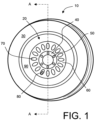
- FIG. 1 there is shown in side view a schematic diagram of a wheel of a heavy commercial vehicle.
- the wheel is indicated generally by 10.
- the wheel 10 comprises a steel hub indicted by 20 and a tyre (tire) denoted by 30.
- the tyre 30 is contemporarily often tubeless, namely does not include any separate inner tube.
- a circular inner flange 40 of the hub 20 includes a circular arrangement of mounting holes 50 for receiving bolts or similar fasteners for attaching the wheel 10 to an axle (not shown in Figure 1 ) of its associated vehicle.
- Extending radially outwards from the inner flange 40 is a substantially frusto-conical web 60 having a radial series of circular or elliptical ventilation holes 70 formed therein as illustrated, for example one of these ventilation holes 70 enables access to an air valve 80 in fluid (air) communication with a volume enclosed by the tyre 30 for purposes of inflating or deflating the tyre 30.
- the frusto-conical web 60 is coupled to a circular rim 90.
- the circular rim 90 is operative to receive the tyre 30.
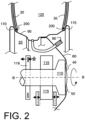
- FIG. 1 a cross-sectional axis is denoted by A-A and a corresponding cross-sectional view of the wheel 10 is shown in Figure 2 for substantially an upper portion of the wheel 10.
- the wheel 10 has a general form which has evolved over many years to substantially an optimal implementation for reasons which will now be elucidated.
- the inner flange 40 is provided with its regularly spaced configuration of mounting holes 50 for mounting securely the wheel 10 using aforementioned bolts or fasteners to an end of a wheel axle 110 of the corresponding vehicle; the wheel axle 110 is operable to rotate about an axis B-B.
- An excess of holes 50 is often provided to be more certain of retaining the wheel 10 onto the wheel axle 110.
- a disc brake 115 is included near an end of the wheel axle 110 in relative close proximity to the frusto-conical web 60 and its associated ventilation holes 70.
- an ABS angular sensor encoder 118 for implementing an ABS baking system for sensing an angular orientation of the axle 110 and hence that of the wheel 10 is contemporarily included as standard components on heavy commercial vehicles; the angular sensor encoder 118 is operable to generate a signal indicative of an angular orientation ⁇ of the wheel 10.
- the angular sensor encoder 118 is often implemented as an optical, electrostatic and/or magnetic sensing device.
- the holes 70 in the frusto-conical web 60 thus enable air circulation to reach one or more metal discs of the disc brake 115 for cooling purposes. Moreover, the holes 70 in the web 60 also assist to reduce an unsprung weight of the wheel 10 without adversely influencing its mechanical strength, as well as providing access for the valve 80.
- the rim 90 has various ridges formed therein to enhance its mechanical strength and also has end ridges 170 to provide reliable retention of the tyre 30 in operation.
- the tyre 30 encloses a volume denoted by 120 which is maintained at an elevated pressure P during operation.
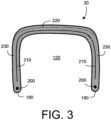
- the tyre 30 includes inner edges 180 for abutment onto the ridges 170 of the circular rim 90.
- the inner edges 180 are often reinforced using steel rings or bands 200 molded into the tyre 30.
- the tyre 30 includes one or more reinforced woven metal and/or reinforced fibre meshes 210 embedded by molding into the tyre 30.
- a tread portion 220 of the tyre 30 has a greater radial thickness in comparison to a lateral thickness of side walls 230 of the tyre 30; the tread portion 220 is thicker for accommodating treads of the tyre 30.
- the tread portion 220 is operable to provide a firm grip to a road surface (not shown) as well as a water draining function, whereas the walls 230 are designed to periodically elastically flex when the wheel 10 with its associated tyre 30 rotate in operation on the road surface.
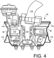
- FIGS. 4 and 5 there are shown diagrams of example contemporary manufactured front and rear wheel assemblies of a heavy commercial vehicle to illustrate how compact regions around vehicle wheels are in practice. There is little extra volume in the front and wheel assemblies for accommodating additional instrumentation for monitoring wheel operating conditions. Amongst other factors, components associated with the aforesaid brake 115 are included in close proximity to the wheel 10 in operation; the brake 115 has associated therewith other components such as servo actuators for forcing brake pad components against a disk component of the brake 115.
- ABS sensor encoder 118 (not shown in Figures 4 and 5 ) for measuring the angular position ⁇ of the wheel 10 when mounted on its axle 110.
- Characteristics which are beneficial to measure in order to monitor wheel 10 and associated tyre 30 condition include temperature T, pressure P and instantaneous acceleration A during operation. It is additionally also feasible to include film strain gauges within or bonded onto walls 230 of the tyre 30 to measure their wall flexure. Temperature T and acceleration A can be measured at various spatial positions on the wheel 10 with mutually different results, whereas the pressure P developed within the volume denoted by 120 enclosed by the tyre 30 in operation is effectively similar because the pressure P equalizes in a relatively short period of time; pressure equalization is estimated to occur within a few milliseconds on account of pressure pulses being able to propagate at a velocity in an order of 250 metres/second within the volume 120.
- the wheel 10 has a diameter in the order of 1 metre.
- Figure 6 illustrates schematically categories of locations whereat sensors are beneficially mounted to the wheel 10. When several sensors are included at each category of location, the several sensors are beneficially distributed at positions angularly distributed around the wheel 10 for providing most representative information indicative of operation of the hub 20 and its tyre 30.
- the first sensor module is capable of monitoring the tyre pressure P by way of fluid (air or gas) communication to the valve 80, is capable of monitoring a temperature T hub of the hub 20 and is capable of sensing accelerations A in one-, two- or three- orthogonal axes (x, y, z) at the hub 20 depending upon type of accelerometer employed.
- a pressure sensor and an accelerometer included in the first sensor module for performing measurements are silicon micromachined integrated electronic components contemporarily known as MEMS ("MicroElectronic Mechanical Systems").
- the temperature T hub of the hub 20 will often be different from the temperature T tyre of the tyre 30; a temperature T mod measured at the first module is hence not ideally representative of the tyre 30 temperature T tyre and thus condition of the tyre 30; the hub 20 will often be subject to direct cooling air flows, and during braking events will be heated up rapidly by warm air flowing from the associated disc brake 115 which, as elucidated in the foregoing, can be subject to sudden peak dissipations of energy of many kiloWatts, for example during and shortly after performing emergency braking.
- the first module at the location L1 is not totally screened by conductive components which renders short-distance wireless communication possible between the first module and an electronic control unit (ECU) or electronic management system of the vehicle.
- the first sensor module at the location L1 is most accessible and susceptible to being retrofitted to vehicles with minimal mechanical changes being required.
- a second sensor module is beneficially mounted to an inside surface of the rim 90 at a location L2 and thereby is subject directly to the pressure P developed within the tyre 30 in operation.
- the second module at this location L2 when measuring the temperature T mod thereat, is capable of providing an accurate measurement of the temperature T tyre of the tyre 30 as well as the aforesaid pressure P.
- one or more accelerometers included within the second module for measuring the acceleration A at the location L2 are at a greater radial distance from the axis B-B (see Figure 2 ) than the first module at the location L1, and are therefore subject to greater radial components of acceleration resulting from rotation of the wheel 10.
- a disadvantage of mounting the second sensor module at the position L2 is that the mesh 210 in combination with the rim 90 have a tendency to form a Faraday cage which severely attenuates wireless transmissions from the second module, unless the second module has an antenna exit through the rim 90, for example a small air-tight hole through which an antenna wire coupled to the second module at the position L2 is extended out onto the frusto-conical web 60 for enhancing wireless communication efficiency.
- the second module at the location L2 is coupled via an antenna wire 300 through an insulated feed-through 310, installed in the rim 90 and operable to withstand the pressure P, to a film metal patch antenna 320; optionally, the patch antenna 320 is affixed to the frusto-conical web 60 for mechanical protection.
- the second module at the location L2 is electrically coupled to the mesh 210 of the tyre 30 and is operable to employ this mesh 210 as an antenna for communicating by wireless to the aforesaid electronic control unit (ECU) or an electronic vehicle management system.
- the second module at the location L2 can be directly electrically coupled by wire through the feed-through 310 or by conductive film connection to the first module at the location L1 and optionally derive power therefrom as well as communicating measurement data thereto.
- a third sensor module is beneficially mounted on an inside surface of the tyre 30 at a location L3, for example by bonding the third module onto the tyre 30 using rubber or plastics material bonding agents or similar before the tyre 30 is mounted to the hub 20; alternatively, use of snap-type press-fit mounting of the third sensor module to the tyre 30 is also feasible and faster to employ when manufacturing and servicing the tyre 30.
- the third module at the location L3 is capable of measuring the temperature T mod thereat and thereby providing a direct representative indication of tyre temperature T tyre , a representative direct indication of the pressure P and is also able to provide an representative indication of flexural characteristics of the walls 230 of the tyre 30 by way of acceleration A measurements or strain gauge measurements; however, the acceleration signals generated by the third module at the location L3 are a complex modulation of various acceleration components as the wheel 10 rotates in operation and its side walls 230 flex, whereas the accelerometer of the first module mounted at the location L1 is operable to generate acceleration signals which include a relatively greater magnitude of linear acceleration components therein which renders the first module at the location L1 potentially better suited for monitoring such linear acceleration components.
- the third module at the location L3 is also coupled to one or more resistive-film or fibre-optical strain gauge sensors (not shown) coupled onto or even embedded within the rubber material of the tyre 30, for example onto the side wall 230 and/or peripheral rim of the tyre 30.
- the third module mounted at the location L3 suffers a similar wireless communication problem to the second module at the location L2 in that the mesh 210 in combination with the rim 90 functions as a Faraday cage to attenuate wireless communication from the volume 120 within the tyre 30.
- the third module at the location L3 is optionally provided with a thin-film conductive antenna 350, for example fabricated by metal film sandwiched between layers of flexible insulating material such as Kapton as illustrated in Figure 8 .
- the antenna 350 is beneficially wrapped around the inner edges 180 and up around an outside wall surface of the tyre 30.
- the second module at the location L2 is also susceptible to being provided with such a thin-film antenna, for example disposed over an edge of the rim 90 and even extending onto the frusto-conical web 60.
- such thin-film antennas are susceptible to being damaged when the tyre 30 is installed onto the hub 20 unless adequately protected with a rubber protective film 360 or similar component added to provide mechanical protection.
- the third module is susceptible to having its antenna coupled electrically to the mesh 210 of the tyre 30 which is then capable of functioning as an antenna; the third module is beneficially provided with an electrical piercing pin for penetrating during installation through an inside of the side wall 230 for providing an electrical connection to the conductive mesh 210.
- the second module at the location L2 can be operable to function as a wireless relay node for conveying signals from the third module at the location L3 via the second module at the location L2 to an electronic control unit (ECU) of the vehicle; such nodal communication between modules mounted onto the wheel 10 will be elucidated in more detail later and corresponds to the modules cooperating to form a communication network.
- ECU electronice control unit
- a fourth module is optionally mounted at a location L4 adjacent a tread region of the tyre 30 and functions in a generally similar manner to the third module mounted at the location L3.
- Measurement signals generated by the first, second and third modules at the locations L1, L2 and L3 respectively will now be further elucidated with reference to Figure 9 .
- FIG 9 there is shown the axis of rotation B-B around which the wheel 10 revolves in operation.
- the wheel 10 is provided via the axle 110 with a leaf spring and/or air pneumatic suspension coupled to a chassis CH of the vehicle; the suspension is denoted by a spring constant K s .
- Forces applied to the tyre 30 from a road surface in contact with the tyre 30 are denoted by a force F(t); the tyre 30 has a spring compliance described by a spring constant K T which is dependent on the pressure P within the tyre 30 and also mechanical design of the tyre 30.
- the first, second and third sensor modules at the locations L1, L2 and L3 respectively are each denoted by a module 400 which circumscribes in operation a radial path denoted by 410 when the wheel 10 rotates around the axis B-B corresponding to the axle 110.
- the radial path 410 has a radius rand the module 400 is inclined at an inclination angle ⁇ relative to a normal radial direction 420.
- the module 400 is operable to measure at least one of:
- the module 400 When the module 400 is mounted at the location L1, it measures the pressure P of the tyre 30 via its valve 80.
- the module 400 is optionally furnished with other types of sensors, for example resistive strain gauges, piezo-electric strain gauges, moisture sensors, and so forth if desired. It is convenient, for identification purposes, that the module 400 is optionally provided with a magnetic sensor, for example implemented using a magnetic reed-relay switch operable to electrically conduct when a permanent magnet having, for example, a near-field magnetic field strength of 100 milliTesla is placed in near proximity to the module 400, for example within a distance of 10 cm therefrom.
- a magnetic sensor for example implemented using a magnetic reed-relay switch operable to electrically conduct when a permanent magnet having, for example, a near-field magnetic field strength of 100 milliTesla is placed in near proximity to the module 400, for example within a distance of 10 cm therefrom.
- Disparity of the measured acceleration A x from Equation 1 with measurements from such an ABS sensor encoder 118 is susceptible to being used detect one or more of:
- checking the acceleration A x against change in turning angle ⁇ determined by the ABS sensor encoder 118 can be, for example, employed to dynamically confirm correct operation of the module 400.
- the module 400 is also capable of measuring accelerations A y and A z in substantially y- and z-directions respectively when the inclination angle ⁇ is non-zero which is, for example, pertinent for the third module at the location L3 when the wall 230 of the tyre 30 flexes, or at the locations L1 and L2 when the hub 20 is loose on its fasteners or skewed in relation to the axle 110.
- Measured acceleration signals are provided approximately as defined in Equations 3 and 4 (Eqs. 3 and 4):
- a z r ⁇ 2 + g sin ⁇ t + ⁇ sin ⁇
- a y r ⁇ 2 + g sin ⁇ t + ⁇ cos ⁇
- the inclination angle ⁇ for the module 400 mounted in an orientation as depicted in Figure 9 is normally substantially zero such that the acceleration A z is normally of a relatively small magnitude and the acceleration A y is a summation of forces arising from the force F(t) resulting from road surface characteristics, centrifugal components r ⁇ 2 arising from turning of the wheel 10 and the force of gravity g modulated by turning of the wheel 10.
- the acceleration A z is normally of a relatively small magnitude
- the acceleration A y is a summation of forces arising from the force F(t) resulting from road surface characteristics, centrifugal components r ⁇ 2 arising from turning of the wheel 10 and the force of gravity g modulated by turning of the wheel 10.
- the acceleration A z is normally of a relatively small magnitude
- the acceleration A y is a summation of forces arising from the force F(t) resulting from road surface characteristics, centrifugal components r ⁇ 2 arising from turning of the wheel 10 and the force of gravity g modulated by
- periodic flexure of the wall 230 of the tyre 30 when the module 400 is mounted at the location L3 results in the inclination angle ⁇ being a strong function of the angle of rotation ⁇ of the wheel 30; the inclination angle ⁇ then becomes substantially, to a first approximation, the flexural angle of the wall 230 of the tyre 30.
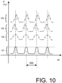
- Figure 10 provides in a signal V1 a qualitative illustration of the angle ⁇ when the module 400 is mounted at the location L3 and the wheel 10 is rotating; the inclination angle ⁇ changes rapidly with flexure of the tyre wall 230 when a portion of the tyre 30 carrying the module 400 on its inside wall 230 comes into contact with a road surface.
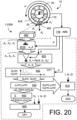
- Examples of a wheel monitoring apparatus is shown in figures 11 , 12 13 and 20 .
- the wheel monitoring apparatus 1 may include any one of the data processing apparatuses 600,680,690 and 2200 shown in figures 11 , 12 , 13 , and 20 .
- Apparatus for use with the present invention is, for example, capable of being employed in a first analysis method including steps of computing expected performance characteristics of the tyre 30 and then comparing the expected performance characteristics against measured characteristics.
- the first method includes steps as follows:
- Such simulation beneficially requires harmonic synthesis to be executed on computing hardware included within the module 400 and/or in an electronic control unit (ECU) of the vehicle to derive the simulated acceleration A z .
- ECU electronice control unit
- Apparatus for use with the present invention is, for example, capable of being employed in a second analysis method including steps of sampling data representative of the acceleration A z occurring in operation at the tyre 30, subjecting the sampled data to harmonic analysis, for example by applying Fast Fourier Transform (FFT) or similar type of transform, then deriving parameters from the harmonic analysis, and then comparing the computed parameters with those that are expected for the tyre 30; if there is a mutual difference between the computed and expected parameters for the tyre 30 by more than a predefined threshold amount, potential failure of the tyre 30 can be detected and the tyre 30 replaced if necessary.
- the second method includes steps as follows are executed:
- the module 400 when mounted on the wall 230 of the tyre 30 as depicted in Figure 8 be provided with a distinguishing identification code (ID).
- ID is beneficially indicative of the characteristics of the tyre 30 to which the module 400 is attached at the position L3.
- the module 400 is operable to communicate the identification code (ID) by wireless to an electronic control unit (ECU) which is operable to execute the variance comparison.
- ECU electronice control unit
- harmonic analysis is also applied to one of more of the acceleration signals A x and A y for further confirming reliability of the harmonic analysis executed pursuant to this second method.
- the module 400 mounted at the location L3 is especially effective for detecting potential problems or defects arising in respect of flexure and dissipation within the tyre 30
- the module 400 mounted at the location L1 is especially effective for measuring variations in asymmetry in the wheel 10, and also for determining a type of asymmetry in the wheel 10 and its associated tyre 30.
- the module 400 is mounted in a non-rotating manner onto the shaft 110 substantially corresponding to the axis B-B.
- more wheel diagnostic information regarding imbalance in the wheel 10 is susceptible to being derived when the module 400 is mounted onto the wheel 10 and operable to rotated with the wheel 10, preferably near its axis B-B of rotation, for example substantially at the location L1.
- monitoring the pressure P as the wheel 10 rotates provides unexpectedly considerable additional information regarding performance of the tyre 30, for example multi-lobed distortions of the tyre 30.
- a data processing apparatus pursuant to the present invention indicated generally by 600; the data processing arrangement is operable to provide wheel- and tyre-monitoring.
- the data processing apparatus 600 is capable of being implemented in at least one of the module 400 and the aforesaid electronic control unit (ECU), depending upon where the processing is susceptible to being most conveniently and efficiently executed.
- the processing arrangement 600 is susceptible to being implemented in at least one of hardware, and software executable in operation on computing hardware.
- the software is beneficially provided as a software product executable on the computing hardware.
- the software product is beneficially conveyed to the apparatus 600 on a data carrier;
- the data carrier is beneficially at least one of: a solid-state electronic data carrier, a wireless signal, an electrical signal, an optical-fibre signal, an optically and/or magnetically readable data carrier.
- components in the linear vertically-directed acceleration A v which correlate with rotation of the wheel 10, for example as referenced by way of the aforesaid ABS encoder sensor 118 providing an indication of the rotation angle ⁇ of the wheel 10 and its angular frequency of rotation ⁇ are of benefit for determining imbalance in the wheel 10, and also potentially elucidating a type of imbalance present in the wheel 10.
- the ABS encoder sensor and its associated signal processing circuits are denoted by 118 in Figure 11 .
- the one or more accelerometers in the one or more modules 400 measuring the accelerations A x and A y as depicted in Figure 9 are all sensitive to linear vertically-directed acceleration in response to rotation of the wheel 10.
- the one or more modules 400 and/or an electronic control unit (ECU) in wireless communication therewith to perform angular resolving, for example as described in Equation 7 (Eq. 7):
- a ⁇ d 1 sin ⁇ t .
- a x + d 2 cos ⁇ t .
- Such angular resolution is executed in operation in a resolver denoted by 620 in Figure 11 .
- the resolver 620 beneficially receives its angular reference for the rotation angle ⁇ from the ABS encoder sensor and its associated circuits 118.
- the resolver 620 is also beneficial in being operable to remove an angular dependent component in the acceleration A v due to gravity g which becomes constant in the resolved acceleration A v . Removal of the acceleration component due to gravity g in the resolved acceleration A v is beneficial for auto-scaling the constants d 1 and d 2 in Equation 7 (Eq. 7) for a condition that the wheel 10 is known to be correctly in balance, for example during a calibration routine performed after the wheel 10 is newly installed on the vehicle..
- the severity of the imbalance can be determined; for example, the amplitude of harmonics Q ( m ) wherein m is a harmonic number in the acceleration A v signal are beneficially individually scaled by a harmonic scaling function y(m) in a scaler 640 and then summed in a summing unit 650 to compute an aggregate S tot summed value.
- Equation 9 corresponds to a decision point DK1 illustrated in Figure 11 .
- the harmonic scaling function y(m) implemented in the scaler 640 is made dependent upon a type of tyre 30 installed on the wheel 10; for example, a robust knobbly tyre installed on the wheel 10 is potentially able to exhibit a greater degree of imbalance before representing any form of potential risk than a lean high-performance high-speed tyre optimized for reduced energy consumption during driving.
- the harmonic scaling function y(m) implemented in the scaler 640 is beneficially also made a function of time t, namely y(m, t) in Equation 8, from an initial time t 0 at which the tyre 30 was installed onto the hub 20.
- the harmonic scaling function y(m) is also beneficially made a function of the number of revolutions as determined from the ABS sensor encoder 118 that the wheel 10 has experienced since the tyre 30 was installed thereon, namely y(m, N) where N is the number of revolutions of the tyre 30.
- a reason for rendering the harmonic scaling function y(m, t) or y(m, N) variable is that imbalance in a well-worn tyre 30 is more likely to potentially result in tyre 30 failure in comparison to a newly-installed substantially unworn tyre 30 whose internal mesh 210 has not been subjected to substantial work-hardening due to repetitive flexure.
- the type of imbalance for the wheel 10 as determined from the amplitude of the harmonics Q(m) is determined from the relative amplitude of given harmonics; such determination is performed by harmonic analysis in an analyzer denoted by 670 in Figure 11 .
- harmonic analysis is beneficially implemented using a set of software rules, by applying a harmonic stencil to the harmonics to identify a signature of a specific type of imbalance present, or by feeding data indicative of the amplitude of the harmonic Q (m) into a neural network trained to recognize occurrence of certain types of defects.
- One or more of the software rules, the harmonic stencil and the neural network are beneficially optionally rendered dependent upon a type of tyre 30 installed onto the hub 20.
- one or more of the rules, the harmonic stencil and the neural network are also beneficially optionally dependent upon an age and/or a degree of wear of the tyre 30.
- normalization of the amplitude of the harmonics Q (m) is beneficially implemented as a part of signal processing employed as depicted in Figure 11 .
- the hub 20 slopping around on its bolts or fasteners gives rise to sudden small jolts of the wheel 10 as the wheel 10 rotates; it has even been known for the frusto-conical web 60 to generate a bell-like ringing tone as it is pulse excited into resonance corresponding to a "cos2 ⁇ mode" of flexure, namely hoop-like deformation of the rim 90 and the frusto-conical web 60.
- the pressure P measured by the module 400 is provided to the harmonic analyzer 630 instead of the resolved acceleration A v in a manner as depicted in Figure 12 ; in Figure 12 , the data processing apparatus 600 adapted to harmonically analyze the pressure P is indicated generally by 680.
- Irregularities in the tyre 30, for example local bulges or weaknesses causing blisters in the tyre 30, are manifest as pressure pulses at certain angular ⁇ positions as the wheel 10 rotates in operation.
- the data processing apparatus 680 functions in a generally similar manner to the data processing apparatus 600 except that the pressure P is analyzed instead of the acceleration A v .
- a data processing apparatus pursuant to the present invention is provided by combining together the data processing apparatus 600, 680 so as to provide for concurrent or periodically alternating harmonic analysis and monitoring of the acceleration A v and the pressure P as depicted in Figure 13 and as indicated by 690 therein; there is provided a switching arrangement 695 in the data processing apparatus 690, either implemented in software or hardware, for selecting between the pressure P and the acceleration A v .
- An advantage of the data processing apparatus 690 illustrated schematically in Figure 13 is that more comprehensive monitoring to the wheel 10 is susceptible to being achieved in operation.
- Aforementioned analysis of flexure of the wall 230 of the tyre 30 as sensed by the module 400 mounted at the location L3 is beneficially compared in the electronic control unit (ECU) and/or within the module 400 with results from harmonic signal analysis performed in respect of one or more modules 400 positioned at one or more of the locations L1 and L2.
- ECU electronice control unit
- a warning message is beneficially then transmitted from the data processing apparatus 600, 680 or 690 as appropriate to a driver of the vehicle and/or to a control centre of the enterprise operating a fleet of such vehicles that there is a need to perform maintenance on the vehicle, for example for devising logistics for a future maintenance schedule for the vehicle.
- logistics can include, for example, prearranging a replacement wheel to be available and informing a service facility regarding a time of arrival of the vehicle for maintenance purposes so that appropriate task scheduling at the service facility can be implemented.
- One or more of the modules 400 mounted at one or more of the locations L1 to L3 are susceptible to being used, optionally in communication with an electronic control unit (ECU), to detect more gradual temporal changes in the tyre 30, for example a gradual reduction in pressure P due to a slow leak therefrom, for example over a period of several weeks or months.
- the one or more modules 400 optionally in cooperation with the aforesaid electronic control unit (ECU) in wireless communication with the one or more modules 400, can be used to monitor sudden depressurization of the tyre 30, for example sudden depressurization and subsequent re-pressurization associated with installing a new replacement tyre 30 onto the hub 20.
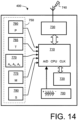
- the module 400 will now be described in overview with reference to Figure 14 .
- the module 400 is required to be robust and also inexpensive in manufacture.
- the module 400 is relatively inaccessible and needs to function reliably without user intervention.
- the module 400 utilizes aforesaid microeletronic mechanical systems (MEMS) technology, for example based upon silicon micromachining fabrication processes.
- the module 400 includes a battery 700 comprising one or more electro-chemical cells operable to provide electrical power, amongst other components, to a computer processor 710.
- a data memory 720 including a software product is coupled in communication with the processor 710; the software product comprises software code which is executable upon the processor 710 and which is operable to coordinate functioning of the module 400.
- the processor 710 has associated therewith a clock (CLK) and an analogue-to-digital (A/D) converter for converting analogue sensor signals to corresponding sampled sensor data; beneficially, the analogue-to-digital (A/D) is based upon a high-speed multi-channel sigma-delta type converter which exhibits modest power consumption.
- Sigma-delta converters are contemporarily employed in power-critical devices such as miniature hearing aids which are battery powered and need to function for long periods without attention, for example for battery change.
- the module 400 further comprises a short-distance wireless interface 730 for providing bidirectional communication to and from the module 400; the wireless interface 730 is beneficially implemented using contemporary Blue Tooth, Weebre or similar wireless interface technology operating pursuant to associated standardized communication protocol.
- the module 400 can alternatively be implemented as a dedicated application specific integrated circuit (ASIC) including logic circuits.
- ASIC application specific integrated circuit
- the module 400 also includes an array of one or more sensors denoted by 750 whose corresponding one or more outputs are coupled to the aforesaid A/D converter.
- the array of sensor 750 includes one or more of:
- the module 400 is susceptible to including other types of sensor not described in detail above.
- the battery 700 is, at least in part, a rechargeable battery and provided with its own electro-magnetic recharging device actuated in response to rotation of the wheel 10 in operation, for example in a manner akin to an automatic wind-up mechanical wrist watch wherein wrist movement is operable to move an imbalance mass to provide watch-spring wind-up energy.
- piezo-electric recharging of the battery 700 in response to rotation of the wheel 10 can be employed.
- the computer processor 710 is operable to perform self-diagnostics and send a warning message via its wireless interface 730 in event of partial or total malfunction occurring within the module 400, and a confirmatory message sent when the module 400 is fully functional; in an event that the module 400 malfunctions, its associated vehicle is not immobilized, but merely results in reduced functionality in respect of wheel and associated tyre monitoring.
- the driver of the vehicle can be informed via the electronic control unit (ECU) regarding reduced functionality and provided with a choice whether or not to continue driving despite malfunctioning of the module 400.
- ECU electronice control unit
- the computer processor 710 detects that the signals from the accelerometer 770 are substantially constant for more than a predefined time period, for example for a time period in a range from a few seconds up to 10 minutes, after cessation of a period of rotation of the wheel 10, the computer processor 710 is beneficially operable to cause the module 400 to assume a hibernating mode to conserve power during which the wireless interface 730 is substantially de-energized.
- the computer processor 710 is beneficially operable to periodically and momentarily activate the wireless interface 730 for short periods to detect "wake-up" commands from the electronic control unit (ECU) of the vehicle.
- ECU electronice control unit
- the computer processor 710 detects that signals from the accelerometer 770 and/or the pressure sensor 760 are temporally varying, for example during a pre-defined time period, the processor 710 is operable to switch the module 400 to its active state, namely non-hibemating, with all its functional parts as shown in Figure 14 brought into operation.
- the module 400 can be explicitly set in a hibernating mode on receipt of a specific hibernate instruction from the electronic control unit (ECU) 950; beneficially, the specific instructions include the identification code (ID) of the module 400 which is to assume such a hibernating state; similarly, the module 400 can be explicitly instructed to assume a functional active state, namely non-hibernating state, by receiving a specific wake-up instruction from the electronic control unit (ECU) 950.
- ID identification code
- all the modules 400 included on the wheels 10 of the vehicle can be set to a hibernate state, or set to a functional active state, by a general explicit instruction wirelessly transmitted from the electronic control unit (ECU) 950; the general explicit instruction is beneficially sent by the electronic control unit (ECU) 950 in response to the driver of the vehicle starting and stopping a combustion engine or an electric traction motor of the vehicle.
- a general explicit instruction wirelessly transmitted from the electronic control unit (ECU) 950; the general explicit instruction is beneficially sent by the electronic control unit (ECU) 950 in response to the driver of the vehicle starting and stopping a combustion engine or an electric traction motor of the vehicle.
- Such an electric traction motor is relevant when the vehicle has a hybrid powertrain or an electric power train provided with electric power from fuel cells.
- the module 400 is operable to receive a synchronization signal for its given associated wheel 10 derived from the aforementioned ABS sensor encoder 118 and its associated circuits associated with the given wheel 10.
- a synchronization signal is beneficially provided from the aforementioned electronic control unit (ECU) 950 of the vehicle operating to provide a data communication hub for the vehicle.
- ECU electronice control unit
- each wheel 10 and its associated modules need to be individually synchronized in respect of their associated ABS sensor encoder 118.
- Data processing performed by the computer processor 710 is beneficially capable of reducing a volume of data to be communicated via the wireless interface 730 to the electronic control unit (ECU).
- ECU electronice control unit
- Such local data processing is of benefit in that it is primarily the wireless interface 730 which consumes a majority of power from the battery 700 when the module 400 is in operation.
- Data flow can be further reduced in the module 400 by the processor 710 transmitting periodically at a beginning of time frames actual data values of sensor signals followed by data representing changes in the data values during each time frame.
- Other approaches for obtaining data compression can also optionally be employed to reduce power consumption at the wireless interface 730.
- the module 400 is operable to transmit accelerometer signal data and pressure P data at a maximum sample rate in a range of 50 samples/second to 200 samples/second for each accelerometer axis and/or the pressure sensor 760 taking into consideration Nyquist sampling criteria.
- a lower rate of up to 1 sample per second for temperature T is optionally employed on account of the temperature T changing less rapidly in comparison to the acceleration A and pressure P.
- the module 400 is also beneficially operable to permit software updates to be downloaded from the electronic control module (ECU) to the module 400, for example via its wireless interface 730, for upgrading or modifying its operation, for example in response to amended safety standards or policy adopted by an operator of the vehicle.
- software updates also enable new and improved data processing algorithms to be later employed, namely software upgrades.
- the module 400 is programmed to have an identification code (ID) which is useable by the aforesaid electronic control unit (ECU) for distinguishing the module 400 from other similar modules 400 on the vehicle, and also from similar types of modules 400 on other vehicles which sporadically pass in near proximity, for example on an adjacent lane during motorway driving.
- the electronic control unit (ECU) is operable to use the identification code (ID) to identify from which portion of the vehicle data conveyed via the module 400 is derived. Such identification will be described in more detail later.
- the computer processor 710 in combination with its wireless interface 730 is also operable to optionally provide a communication networking function.
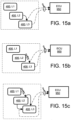
- the computer processor 710 has a directly wired interface so that a first module 400 mounted at the location L1 on the wheel 10 is capable of being directly coupled via a wire or optical fibre communication link through the feed-through 310 as depicted in Figure 7 to a second module 400 mounted at the position L2 on the rim 90 within the volume 120 as depicted in Figure 15a .
- the processor 730 of the first module 400 located at the location L1 is thereby operable to:
- data signals from the second module 400 at the location L2 can be:
- Such a communication link is also susceptible to being used in reverse for conveying aforementioned ABS synchronization signals via the first module 400 at the location L1 to the second module 400 at the location L2 as depicted in Figure 15b .
- the second module 400 at the location L2 is able to function as a network relay for a third module 400 mounted at the location L3.
- the second module 400 at the location L2 is coupled by wire or optical fibre via the feed-through 310 to the first module 400 at the location L1
- the third module 400 at the location L3 is coupled by wireless to the second module 400 at the location L2 as depicted in Figure 15c .
- Wireless communication between the third module 400 at the location L3 to the second module 400 at the location L2 is beneficial in view of a potentially large number of times the third module 400 at the location L3 moves in respect of the second module 400 at the location L2 in response to flexure of the wall 230 of the tyre 30 as the wheel 10 rotates in operation; wires or similar direct connections linking the modules at the locations L2 and L3 would not only be prone to breakage due to work-hardening effects, but would also be impractical to attach once the tyre 30 has been installed onto the hub 20 on account of the volume 120 then being user-inaccessible.
- the third module 400 at the location L3, mutatis mutandis for the module 400 at the location L4, is electrically coupled to the mesh 210 of the tyre 30 which is used as a highly effective patch radio antenna for communicating by wireless to the electronic control unit (ECU).
- the third module 400 at the location L3 is capable of function as a wireless relay node for communicating data from the second module 400 mounted at the location L2 on the rim 90.
- Figure 15d Such a configuration is illustrated in Figure 15d .
- modules 400 at the locations L1, L2; L3 and L4 are also feasible.
- the modules 400 are optionally operable to all communicate directly by wireless via their wireless interfaces 730 directly with the electronic control unit (ECU) as depicted in Figure 15e .
- the modules 400 are dynamically reconfigurable depending upon received wireless signal strength at the electronic control unit (ECU), for example between various network modes as elucidated in the foregoing with reference to Figures 15a to 15e .
- Such flexibility to reconfigure a communication network provided by the modules 400 is beneficial when wheels 10 are swapped around or changed on the vehicle. Such adaptability will be described in more detail later.
- the first, second, third and fourth modules 400 mounted at the locations L1, L2, L3 and L4 respectively each are provided with their uniquely-defining identification codes (ID) which the modules 400 are operable to employ when communicating with the electronic control unit (ECU) for distinguishing their data from that of other modules 400.
- identification codes (ID) are beneficial when the electronic control unit (ECU) sends synchronization signals derived from the ABS sensor encoders 118, for example in a situation where considerable data processing is performed locally at the modules 400 to reduce a quantity of data to be communicated via their wireless interfaces 730 to the electronic control unit (ECU) in operation.
- FIG 16 there is shown in plan view the aforementioned vehicle indicated generally by 900.
- the vehicle 900 is driven in operation by the aforesaid driver denoted by 910 in Figure 16 .
- the vehicle 900 comprises a front tractor unit 920 including a combustion engine 930 operable to provide motive force to a pair of steerable front wheels 10 beneficially implemented in a manner substantially as depicted in Figure 4 .
- the combustion engine 930 is at least one of: a contemporary cylinder combustion engine, a combustion engine with turbocharger, an electric series or parallel hybrid engine, a gas turbine engine, a fuel cell system providing electrical power to associated electric motor traction.
- the vehicle 900 also comprises a trailer unit 940 having two sets of double rear wheels 10 as shown; the double rear wheels 10 are beneficially implemented in a manner as depicted in Figure 5 and are optionally also steerable in a manner similar to the front wheels 10 of the front tractor unit 920.
- Other configurations of wheels 10 for the vehicle 900 are possible and Figure 16 is merely one example for describing the present invention.
- the vehicle 900 is further provided with the aforementioned electronic control unit (ECU) denoted by 950; the electronic control unit (ECU) 950 includes a computer processor together with data memory and one or more wireless interfaces and electrical interfaces, the computer processor being operable to execute one or more software products including executable software code.
- ECU electronice control unit
- the electronic control unit (ECU) 950 is coupled in communication with a console 915 operated by the driver 910.
- the electronic control unit (ECU) 950 is also coupled in communication with the combustion engine 930 for performing engine management and monitoring functions, for example deliberately limiting a speed, or recommending to the driver a suitable speed, at which the driver 910 is able to drive the vehicle 900 in an event of the electronic control unit (ECU) 950 detecting a problem, or potential problem, with one or more wheels 10 of the vehicle 900.
- the electronic control unit (ECU) 950 is also wirelessly coupled to one or more modules 400 mounted on one or more of the wheels 10 of the vehicle 900 as elucidated in the foregoing.
- the electronic control unit (ECU) 950 includes an antenna 960 for transmitting and receiving wireless signals as denoted by 970 for enabling the vehicle 900 to communicate with other facilities, for example a control centre 1000 of an enterprise organising logistics for a fleet of such vehicles 900, or to a service facility 1010 whereat wheels 10 and their tyres 30 of the vehicle 900 can be serviced or replaced as depicted in Figure 16 .
- the electronic control unit (ECU) 950 is operable to monitor operation of the wheels 10 of the vehicle 900 and automatically inform the control centre 1000 of a need to inform the driver 910 to drive the vehicle 900 into the service facility 1010 for servicing its wheels 10 and associated tyres 30, for example as part of a delivery schedule planned for the vehicle 900, thereby causing less disruption to a service provided by the enterprise to its customers.
- a visit to the service facility 1010 is optionally invoked in response to weather conditions or time, for example in connection with exchanging summer tyres 30 to winter tyres 30 in Northern Europe and North America.
- the electronic control unit (ECU) 950 is also wirelessly coupled to a global positioning system (GPS) 1020 for determining in operation a spatial position of the vehicle 900 upon the surface of the Earth.
- GPS global positioning system
- the GPS system 1020 is, for example, that managed by US authorities or an equivalent European Galileo positioning system.
- the GPS system 1020 is based on a mobile telephone, namely cell net, system known as GPRS or similar.
- the electronic control unit (ECU) 950 is operable to determine whereat the vehicle 900 is located and convey this positional information to the control centre 1000 so that the control centre 1000 is aware of the position of the vehicle 900.
- control centre 1000 can direct the vehicle 900 to a suitable geographically convenient service centre 1010.
- control centre 1000 is also operable to arrange, based upon knowledge of the position of the vehicle 900, for the tractor 920 to be decoupled from its trailer 940 at a suitable geographical location so that an alternative tractor can be rapidly coupled to the trailer 940 to haul the trailer 940 and its contents further promptly to its destination, for example to a customer; the tractor 920 can then be serviced without disrupting time-critical deliveries in the trailer 940 to the customer.
- the service centre 1010 can also be warned in advance, either directly from the vehicle 900 or indirectly via the control centre 1010 or both, regarding arrival of the vehicle 900 together with an indication of a likely problem with one or more wheels 10 of the vehicle 900.
- Such notification of problems regarding the vehicle 900 to the control centre 1000 and optionally to the service centre 1010 is susceptible to occurring automatically without the driver 910 needing to interpret messages and actively inform one or more of the control centre 1000, the service centre 1010 or the customer. An improvement of service to the customer is thereby susceptible to being achieved.
- the electronic control unit (ECU) 950 is operable to generate various warning messages.
- the electronic control unit (ECU) 950 is operable to send a warning to at least one of the control centre 1000 and the driver 910 of such malfunction, but continue to monitor other wheels 10 whose modules 400 are continuing to function correctly.
- Such graceful decline in monitoring functionality of the modules 400 mounted on one or more of the wheels 10 is susceptible to improving operational robustness of the vehicle 900, namely failure of one or more of the modules 400 does not immobilize the vehicle 900.
- a potential cause of one or more of the modules 400 failing is exhaustion of batteries 700 therein, or replacement of a tyre 30 for example.
- the present invention is concerned with methods of identifying locations of wheel modules included in wheels and/or their associated tyres; for example, to a method of identifying locations of wheel modules operable to monitor characteristics of wheels and/or their associated tyres and conveying information indicative of these aforementioned characteristics via a communication link to an electronic control unit (ECU) and/or control system, for example for user-display.
- ECU electronice control unit
- the present invention also concerns wheel modules for use in implementing aforementioned methods; various implementations of these wheel modules have been described in the foregoing and are also described in following paragraphs.
- the vehicle 900 has many wheels 10, namely ten for the example described in the foregoing.
- certain of the wheels 10 are beneficially provided with fewer than three modules 400 so that a total of around five to twenty modules 400, for example ten modules 400, are conveniently employed altogether for the vehicle 900 for example.
- a problem arises in programming the electronic control unit (ECU) 950 to recognize at which wheel the respective modules 400 are positioned in the vehicle 900.
- ECU electronice control unit
- Such "calibration" is important for providing the driver 910, the control centre 1000 and/or the service centre 1010 with correct information about which wheel 10 of the vehicle 900 is potentially defective, potentially defective or needing attention, for example charging with compressed air to increase its pressure P or needing a tyre 30 change.
- Certain types of unbalance defects or tyre wall 230 defects cannot be ascertained by mere casual visual inspection of a wheel 10 and its tyre 30.
- tangential acceleration is denoted by A x
- radial acceleration is denoted by A y
- lateral acceleration is denoted by A z .
- FIG 17a there is depicted a first embodiment of a method of "calibrating" the vehicle 900 by causing the vehicle 900 to perform a right-hand turn of radius R about a centre of rotation W.
- the first embodiment is concerned with the lateral acceleration A z ; see Figure 9 for an appropriate spatial definition of the acceleration A z .
- the method of "calibration" relies upon a characteristics that left-side wheels 10al, 10bl, 10cl on an outside of the right-turn experience a greater centrifugal force manifest as the acceleration A z as sensed by the modules 400 mounted associated with these left-side wheels 10al, 10bl , 10cl in comparison to right-side wheels 10ar, 10br, 10cr on an inside of the turn.
- the front wheels 10al, 10ar experience an increase in acceleration temporally before the middle wheels 10bl , 10br and especially the rear wheels 10cl, 10rl.
- the driver 910 inputs to the electronic control unit (ECU) 950, for example by depressing a suitable switch, key or button on the console 915, that the driver 910 is desirous to invoke the method according to the first embodiment of the invention of identifying locations of the modules 400 on the vehicle 900, namely "calibrating" the vehicle 900.
- the driver 910 then drives the vehicle 900 for a short distance in a straight direction so that the lateral acceleration A z of the wheels 10 is substantially zero.
- the driver 910 then turns a steering wheel of the vehicle 900 at the console 915 to pivot the front wheels 10al, 10ar to cause the vehicle 900 to execute the aforementioned right-turn from the positions Q1 to Q5 and then turns the steering wheel straighten the front wheels 10al, 10ar to cause the vehicle 900 to continue further in a straight trajectory after the position Q5.
- the modules 400 are operable to measure the lateral accelerations A z from its wheels 10 and communicate by wireless corresponding sampled data to the electronic control module (ECU) 950 which stores the sample data in its memory; the sample data is communicated together with the identification codes (ID) of the modules 400 providing the sampled data.
- ECU electronice control module
- the electronic control unit (ECU) 950 terminates its collation of sample data and then progresses to analyze the sample data stored in its memory. By comparing relative magnitudes of the accelerations A z and also positions where they each have a maximum magnitude, the electronic control unit (ECU) 950 is able to identify where the modules 400 providing the sample data are located in the vehicle 900.
- Figure 17b is a graphical illustration of acceleration signals A z for the wheels 10al, 10ar, 10bl, 10br, 10cl, 10cr as denoted by curves 1500, 1510, 1520, 1530, 1540, 1550 respectively.
- the driver 910 enters information into the electronic control unit (ECU) 950 indicative of whether the driver 910 is intending to implement the method accoding to the first embodiment of the invention in respect of a right-hand turn or a left-hand turn.
- information regarding a direction is turned during calibration can be automatically derived from a steering angle sensor associated with a steering wheel of the vehicle 900; such steering direction information is provided to the electronic control unit (ECU) 950.
- this method of "calibration" is not optimal for establishing locations of modules 400 in the location L3 on wheels 10, but is satisfactory for identifying locations of modules 400 mounted at locations L1 and L2.
- a second embodiment of the invention relates to a method of "calibrating" the vehicle 900 which involves monitoring instantaneous pressure P as sensed by the modules 400 for each of their respective wheels 10.
- P instantaneous pressure
- wheels 10 on an outside of a curved trajectory followed by the vehicle 900 when executing the turn will momentary have a high degree of elevation of their pressure in comparison to wheels 10 on an inside of the curved trajectory.
- Such pressure change is especially pertinent for the front wheels 10al, 10ar.
- wheels 10 on an outside of a curved trajectory followed by the vehicle 900 when executing the turn will momentary have a higher degree of elevation of their pressure in comparison to wheels 10 on an inside of the curved trajectory, however with less difference than what appears at the front wheels. Furthermore, especially for non steerable rear axles, the change in pressure will be delayed and occur at a lower rate in comparison to the change in pressure occurring ad the front axle.
- Figure 10a show examples of how the pressure is changed when a vehicle makes a turn.
- P1 At first when the vehicle is caused to drive straight ahead, generally an identical pressure level P1, is generated from each of the sensors in the modules respectively. Since according to the invention, the identification of each modules location will be dependent on analyses of the change of pressure for each module, it is not necessary that the pressure level for each sensor when driving straight ahead is equal. In this example, this is assumed for simplifying an illustration of how the method according to the invention operates. In the event the pressures detected by respective sensor module 400 are different, the pressure levels may be normed, or alternatively, the level or pressure change for each sensor can be monitored.
- the vehicle starts to turn, which is first noticed by a pressure increase at the outer front wheel, and a corresponding pressure decrease at the inner front wheel.
- a right turn is made generating a decrease of pressure at the right front wheel 10ar and an increase of pressure at the left front wheel.
- the vehicle has fixed rear axles, there is a delay in time to t2 until the vehicle starts turning around the first rear axle having a middle set of wheels 10bl, 10br.
- the change in pressure will also take place at a lower rate, dP/dt, in comparison to the change of pressure of the front wheels.
- the vehicle starts turning around the second rear axle having a rear set of wheels 10cl, 10cr.
- the change in pressure will also take place at a lower rate, dP/dt, in comparison to the change of pressure of the front wheels.
- the rate of the change in pressure at the second axle may be of the same magnitude as for the first rear axle.
- the pressure signals from the sensor modules 400 are shown during an entry and exit of a curve, that is from a phase where the vehicle starts turning after having propagated straight ahead until a phase where the vehicle starts driving straight ahead after exiting a curve.
- the front wheels 10ar, 10al first enters the curve with a corresponding steep change of pressure, and that the first and second rear axles with the wheels 10br,10bl, 10cl, 10cr respectively, follow in sequence at a lower rate of change.
- the pressure level at the front wheels 10ar, 101 will change first and at a high rate.
- the first and second rear axles with the wheels 10br,10bl, 10cl, 10cr respectively will follow in sequence at. a lower rate of change.
- the timing of when the change in pressure occur indicates at which axle the wheel, and thus the sensor is located.
- the timing the change in pressure at the front axle and the steered rear axle may be simultaneous.
- the rate at which the pressure changes will be lower at the rear axle for normal vehicles having front and rear steered axles.
- the driver 910 inputs to the electronic control unit (ECU) 950, for example by depressing a suitable switch, key or button on the console 915, that the driver 910 is desirous to invoke the "calibrating" according to the second embodiment of identifying locations of the modules 400 on the vehicle 900, namely "calibrating" the vehicle 900.
- the driver 910 then drives the vehicle 900 for a short distance in a straight direction so that the pressure level in each tyre P 1 ,...P N may be recorded.
- the driver 910 then turns a steering wheel of the vehicle 900 at the console 915 to pivot the front wheels 10al, 10ar to cause the vehicle 900 to execute the aforementioned right-turn from the positions Q1 to Q5 and then turns the steering wheel straighten the front wheels 10al, 10ar to cause the vehicle 900 to continue further in a straight trajectory after the position Q5.
- the modules 400 are operable to measure the pressure at its wheels 10 and communicate by wireless corresponding sampled data to the electronic control module (ECU) 950 which stores the sample data in its memory; the sample data is communicated together with the identification codes (ID) of the modules 400 providing the sampled data.
- ECU electronice control module
- the electronic control unit (ECU) 950 terminates its collation of sample data and then progresses to analyze the sample data stored in its memory. By comparing relative pressure differences from the initial pressure levels and also positions where they each start to deviate from the initial values by more than a set value, the electronic control unit (ECU) 950 is able to identify where the modules 400 providing the sample data are located in the vehicle 900.
- the driver 910 enters information into the electronic control unit (ECU) 950 indicative of whether the driver 910 is intending to implement the method accoding to the first embodiment of the invention in respect of a right-hand turn or a left-hand turn.
- information regarding a direction is turned during calibration can be automatically derived from a steering angle sensor associated with a steering wheel of the vehicle 900; such steering direction information is provided to the electronic control unit (ECU) 950.
- the physical parameter is an angular velocity derived from a signal generated by said one or more modules (400).
- the method includes the steps of:
- the senor may be an accelerometer which generates acceleration signal components in the tangential and/or radial direction ( A x , A y ) derived from said one or more modules (400).
- a measure of the angular velocity of each wheel is derived from a sensor signal from the modules.
- the wheels on the outside in the curve will follow a longer route than wheels on the inside in a curve, which enables a computer to separate the signals from modules located on the left and right side of the vehicle when the direction of the curve is known. Furthermore, as have been explained before in relation to the first embodiment of the invention, when entering a curve, the front axle will be start turning first followed by the wheels on the middle axle (if one is present) and the rear axle.
- FIG 10c the angular position of the wheels as a function of time is shown. At first all wheels travels at equal velocities. At the time t1 a first separation is made by the first axle outer wheel, which travels at an angular velocity which is higher than the all the other wheels due to the fact it follows a longer route.
- the signal generated by a module located at the front outer wheel will thus be characterised by a angular velocity ⁇ ar which is greater in magnitude than the signals from the other modules.
- the angular velocity characterising each signal provided from the modules 400 may be determined in any conventional manner, for instance by estimating the time between passage of the average level determined by the constant A 0 .
- the driver 910 inputs to the electronic control unit (ECU) 950, for example by depressing a suitable switch, key or button on the console 915, that the driver 910 is desirous to invoke the "calibrating" according to the second embodiment of identifying locations of the modules 400 on the vehicle 900, namely "calibrating" the vehicle 900.
- the driver 910 then drives the vehicle 900 for a short distance in a straight direction so that the angular velocity for each tyre ⁇ 1 ,... ⁇ N may be recorded.
- the driver 910 then turns a steering wheel of the vehicle 900 at the console 915 to pivot the front wheels 10al, 10ar to cause the vehicle 900 to execute the aforementioned right-turn from the positions Q1 to Q5 and then turns the steering wheel straighten the front wheels 10al, 10ar to cause the vehicle 900 to continue further in a straight trajectory after the position Q5.
- the modules 400 are operable to measure the tangential acceleration at its wheels 10 and communicate by wireless corresponding sampled data to the electronic control module (ECU) 950 which stores the sample data in its memory; the sample data is communicated together with the identification codes (ID) of the modules 400 providing the sampled data.
- ECU electronice control module
- the electronic control unit (ECU) 950 terminates its collation of sample data and then progresses to analyze the sample data stored in its memory. By comparing relative differences in an angular velocity for each wheel from the initial angular velocities and also positions where they each start to deviate from the initial values, the electronic control unit (ECU) 950 is able to identify where the modules 400 providing the sample data are located in the vehicle 900.
- the driver 910 enters information into the electronic control unit (ECU) 950 indicative of whether the driver 910 is intending to implement the method accoding to the first embodiment of the invention in respect of a right-hand turn or a left-hand turn.
- information regarding a direction is turned during calibration can be automatically derived from a steering angle sensor associated with a steering wheel of the vehicle 900; such steering direction information is provided to the electronic control unit (ECU) 950.
- Steps of the aforementioned general method of "calibrating” and the methods of “calibrating” the vehicle according to the invention can be combined in various different combinations to more reliably detect where the modules 400 are located on wheels of the vehicle 10.
- Such methods are susceptible to simplifying operation of the vehicle 900 and avoiding error in comparison to the first method of "calibrating" the vehicle 900 by magnetic activation.
- a potential operational situation encountered by an enterprise denoted by 2000 operating a fleet of the vehicles 900 from its control centre 1000 with several service centres 1010a, 1010b, 1010c and collections of wheels 10 in reserve at the centres 1010a, 1010b, 1010c and/or depots 2010a, 2010b is that wheels 10 mounted on the vehicles 900 and wheels 10 in storage at the service centres 1010 and/or the depots 2010 potentially have mutually different configurations of modules 400 mounted thereonto as depicted by various cross-hatching patterns employed in Figure 18 .
- modules 400 may also be configured with different combinations of sensors; for example, some modules 400 will include pressure sensors 760 and temperature sensors 765, whereas other modules will include accelerometers 770 and temperature sensors 765, and yet others will include a full complement of pressure sensors 760, temperature sensors 765 and accelerometers 770.
- the accelerometers 770 are potentially one-, two- or three-axis accelerometers.
- the enterprise 2000 may be desirous to have certain defined configurations of modules 400 on front wheels 10a of its vehicles 900 and other defined configuration of modules 400 on rear wheels 10b, 10c of its vehicles 900.
- modules 400 on any given vehicle 900 is potentially dynamically altering as wheels 10 are removed from and installed onto the vehicles 900 as part of a maintenance schedule adopted by the enterprise. Furthermore, certain modules 400 may potentially occasionally fail due to their batteries 700 becoming exhausted. In view of such potential diversity as represented by different shaping for the wheels 10 in Figure 18 , none of the aforesaid sixth methods of "calibrating" the vehicles 900 will be optimal in all circumstances.
- the aforementioned apparatus 600, 680, 690 is beneficially implemented in a dynamically alterable manner in response to different configurations of modules 400 being available as determined by one or more of the aforementioned methods of "calibrating" the vehicles 900, or in response to declared functionality as communicated from the modules 400 to the electronic control unit 950.
- the modules 400 respond to the aforementioned message sent out from the electronic control unit (ECU) 950 for the modules in a given vehicle 900 to identify themselves, for example in step (a) of the general method of "calibration", the modules 400 respond by not only declaring their identification code (ID) but also a description of their functionality, namely an indication of their individual configurations of sensors included therein, and optionally their capacity to execute local data processing thereat.
- ID identification code
- the modules 400 respond by not only declaring their identification code (ID) but also a description of their functionality, namely an indication of their individual configurations of sensors included therein, and optionally their capacity to execute local data processing thereat.
- modules 400 are operable to respond with their identification codes (ID) together with information that they each have only a pressure sensor 760 and a temperature sensor 765
- other modules 400 are operable to respond with their identification codes (ID) together with information that they each have only a x- and y- axis accelerometer 770 together with a temperature sensor 765, and so forth for inclusion in the aforementioned list or record kept at the electronic control unit (ECU) 950.
- the electronic control unit (ECU) 950 is thereby able to dynamically select a most suitable method of "calibrating" the vehicle 900 and inform the driver 910 on the console 915 accordingly.
- the electronic control unit (ECU) 950 being aware of the functionality of its wheels 10, it is able to convey such information to the control centre 1000 for use in directing maintenance schedules for the vehicle 900, for example sending the vehicle 900 to a service centre 1010 which has a suitable equivalent replacement wheel 10.
- the enterprise 2000 therefore beneficially implements in its vehicles 900 a general wheel monitoring method including steps as follows:
- the general wheel monitoring method described above is susceptible to being implemented automatically by way of computer-based supervision from the control centre 1000 and/or from one or more of the service centres 1010.
- the service centres 1010 and/or the depots 2020 are operable to communicate their inventory of wheels 10 in a dynamic manner.
- the control centre 1000 is also operable to maintain dynamically a record of operational status of its vehicles 900 at least in respect of their wheels 10 furnished with on or more modules 400 pursuant to the present invention.
- Adoption of the general wheel monitoring method is beneficial in that safety and reliability is improved which potentially may bring insurance premium benefits for the enterprise 2000, as well as potentially enhancing the quality of their service to their customers.
- the module 400 is employed when implementing the present invention in various configurations.
- the module 400 includes the accelerometer 770 as depicted in Figure 14
- the module 400 can be regarded as being a form of inertial navigation unit (INU).
- INU inertial navigation unit
- inertial navigation units for steering vehicles such as rockets, helicopters, aircraft and so forth
- INU inertial navigation units
- achieving such accurate angular alignment requires accuracy and precision which is potentially time consuming and costly to achieve.
- the one or more modules 400 be mountable to the wheel 10, for example at one or more of the locations L1 to L4, without a high degree of mounting precision and accuracy being necessary.
- the z-axis and the y-axis are pertinent at the locations L1 to L4.
- the x-axis is dependent upon a radius r at which the point is from the axis B-B.
- Figure 19 corresponds to Figure 9 for the inclination angle ⁇ being substantially zero.
- the acceleration A z is especially useful, as depicted in Figure 10 , for monitoring flexural characteristics of the tyre 30 as well as detecting whether or not the wheel 10 is at a skewed angle relative to its axle 110.
- the vertical acceleration A v resolved from A x and A y acceleration components measured at a given module 400 is beneficial for monitoring imbalance in the wheel 10 and also a type of imbalance involved.
- the module 400 is potentially mounted in an angularly misaligned position on the wheel 10 such that its local orthogonal axes denoted by x', y', z' do not align with true axes x, y, z required for generating highly useful A x , A y , A z acceleration signals.
- Accelerations A x ' , A y ', A z ' correspond to measurements of accelerations along the local orthogonal axes x', y', z' respectively. It is feasible to resolve the accelerations A x ', A y ', A z ' in respect of the true axes x, y, z as provided by a matrix mapping as defined by Equation 10 (Eq.
- Suitable values for the angles ⁇ and ⁇ are susceptible to being computed in an iterative manner so that Equations 11 and 12 can be substantially achieved, or at least a minimized condition in respect of the angles ⁇ and ⁇ is susceptible to being achieved.
- spurious road surface noise present in the accelerations A x ', A y ', A z ' potentially requires a minimum condition to be searched for as a best approximation for satisfying Equations 11 and 12.
- Optimal values for the angles ⁇ and ⁇ can either be found from an explicit solution for Equations 10, 11 and 12, or iteratively by recomputing for various combinations of the angles ⁇ and ⁇ for a sample of signals representative of the accelerations A x ' , A y , A z ' until a nearest approximation to Equations 11 and 12 is achieved.
- Computation of the angles ⁇ and ⁇ is beneficially performed at the electronic control unit (ECU) 950.
- distributed computing performed at the module 400 can also be employed for computing the angles ⁇ and ⁇ .
- application of these angles ⁇ and ⁇ pursuant to Equation 10 to obtain the accelerations A x , A y , A z for monitoring operation of the wheel 10, for example as depicted in Figures 11 and 13 is susceptible to being implemented at the electronic control unit (ECU) 950 or at the module 400, or distributed between both the electronic control unit (ECU) 950 and the computer processor 710 of the module 400 to spread computational load.
- Equations 10 to 12 are an example of auto-resolving accelerations sensed by the accelerometer 770 of the module 400 to generate corresponding acceleration signals suitable for processing as depicted in Figure 11 and 13 with associated description in the foregoing.
- auto-resolving for a three-axis accelerometer 770 is described, such approximate auto-resolving can be also be employed when the accelerometer 770 is a two-axis accelerometer for example in simplified form.
- Auto-resolving is also susceptible to being referred to as auto-alignment.
- Auto-resolving for example as described in Equations 10 to 12, is of benefit in that the one or more modules 400 mounted one or more of the locations L1 to L4 do not need to be mounted onto the wheel 10 pursuant to highly precise angular alignment, thereby simplifying mounting of the one or more modules 400 to the wheel 10 and potentially reducing assembly and mounting costs.
- a corresponding apparatus as indicated generally by 2200 in Figure 20 wherein an auto-resolver is denoted by 2210.
- the apparatus 2200 includes at least one module 400 whose accelerometer 770 is operable to generate the acceleration signals A x ' , A y , A z ' which are firstly auto-resolved in the auto-resolver 2210 to generate corresponding resolved acceleration data for the accelerations A x , A y , A z .
- the resolved accelerations A x , A y , A z are then further resolved in the resolver 620 in respect of the rotation angle ⁇ of the wheel 10 as sensed by the ABS sensor encoder 118 to generate corresponding vertical acceleration A v signal data and also acceleration A z signal data.
- the acceleration A v , A z signal data are then subject to harmonic analysis in the harmonic analyzer 630 to generate corresponding series of harmonic coefficients Q v ( m ) and Q z ( m ) respectively in relation the angular frequency ⁇ of rotation of the wheel 10.
- the harmonic coefficients Q v ( m ) and Q z ( m ) are then optionally subject to harmonic scaling in the scaler 640 to generate corresponding scaled harmonic coefficients y v (m).
- Q z (m) which are then subject to analysis in terms of absolute magnitude and relative magnitude to determine whether or not:
- one or more modules 400 can be optionally mounted at one or more of the locations L1, L2 and L3.
- the apparatus 2200 is susceptible to being implemented in hardware, in software executable on computing hardware, or a combination of such hardware and software.
- the apparatus 2200 is susceptible to being implemented substantially in the electronic control unit (ECU) 950, on the module 400, or on both the module 400 and electronic control unit (ECU) 950 in combination.
- the software is optionally supplied as one or more software products on one or more data carriers.
- the software is optionally dynamically reconfigurable depending on potentially changing configurations of one or more modules 400 included on the wheel 10.
- the apparatus 2200 illustrated in Figure 20 is susceptible to being modified in a manner akin to the apparatus 690 illustrated in Figure 13 , namely concurrently or alternately being operable to harmonically analyze a sampled signal representative of the pressure P in the volume 120 of the tyre 30.
- the auto-resolver 2210 requires calibrating in order to determine its correction angles a and ⁇ as elucidated in the foregoing.
- Such calibration is beneficially implemented as part of the aforesaid methods of "calibrating" the modules 400, namely enabling the electronic control unit (ECU) 950 to identify which modules 400 with which it is required to communicate on the vehicle 900, wherein the modules 400 are mounted at various locations on wheels 10 of the vehicle 900, with potentially mutually different operating characteristics of the modules 400; as elucidated earlier, a situation potentially arises in operation where certain wheels 10 of the vehicle 900 are provided with a more comprehensive set of modules 400 in comparison to other wheels of the vehicle 900, in a potentially temporally dynamically changing manner.
- ECU electronice control unit
- a measure of the angular orientation ⁇ of the wheel 10 can also be computed, as elucidated in the foregoing, on a basis of the gravitational force g acting upon the accelerometer 770 of the module 400.
- the gravitation force g is manifested in operation in the acceleration components A x , A y and is superimposed on any acceleration experienced at the wheel 10 due to general acceleration or deceleration of the vehicle 900.
- the angular orientation ⁇ of the wheel 10 is derived from the acceleration components A x , A y , in addition to or as an alternative to the ABS encoder sensor 118, such derivation does not preclude the use of aforementioned auto-alignment of the axes x', y', z' of the module 400 to the true x, y, z axes of the wheel 10 representative of orthogonal tangential and lateral axes respectively, see Figure 9 .
- Such derivation of the angular orientation ⁇ enables the present invention to be, for example, applied to vehicles which are not equipped with ABS braking or partially equipped with ABS braking on only certain of their wheels.
- such derivation enables the present invention to be retrofitted in certain situations to older vehicles which are not provided with ABS braking.
- Flexure of the side-wall 230 of the tyre 30 is also susceptible to being sensed by a first module 400 mounted at the location L3 moving in respect of a second module 400 mounted at the location L2 in close spatial proximity to the first module 400. In operation, flexure of the side-wall 230 causes a relative spatial distance between the first and second modules 400 to vary correspondingly.
- the first module 400 is provided with a source of radiation, and the second module 400 is operable to monitor a magnitude of a portion of the radiation received thereat and convey a corresponding signal by wireless to the electronic control unit (ECU) 950.
- the signal is representative of a change of spatial separation between the first and second modules 400 as a function of their wheel 10 rotating.
- the second module 400 is provided with a source of radiation, and the first module 400 is operable to monitor a magnitude of a portion of the radiation received thereat and convey a corresponding signal by wireless, for example using the mesh 210 of the tyre 30 as a wireless patch antenna, to the electronic control unit (ECU) 950.
- the signal is representative of a change of spatial separation between the first and second modules 400 as a function of their wheel 10 rotating.
- the radiation can be at least one of: a substantially constant magnetic field generated by a permanent magnet, an alternating magnetic field, ultrasonic radiation, wireless radiation, pulsed optical radiation, capacitive electrostatically-coupled radiation to mention a few examples.
- Ultrasonic radiation is beneficially generated and received using piezo-electric transducers.
Landscapes
- Engineering & Computer Science (AREA)
- Mechanical Engineering (AREA)
- Physics & Mathematics (AREA)
- General Physics & Mathematics (AREA)
- Arrangements For Transmission Of Measured Signals (AREA)
- Measuring Fluid Pressure (AREA)
Claims (14)
- Procédé d'identification d'emplacements d'un ou plusieurs modules (400) d'un appareil (1) mis en oeuvre dans un véhicule (900) pour surveiller le fonctionnement d'au moins une roue (10) du véhicule (900), ledit appareil (1) comportant un ou plusieurs modules de capteur (400) montés fonctionnellement pour tourner avec ladite au moins une roue (10), ledit ou lesdits modules (400) étant couplés fonctionnellement en communication avec un agencement de traitement (710, ECU 950) dudit véhicule (900), ledit ou lesdits modules (400) étant fonctionnels pour déterminer au moins un paramètre physique de ladite roue (10) et pour générer au moins un signal de capteur correspondant destiné audit agencement de traitement (950), ledit agencement de traitement (710, ECU 950) étant fonctionnel pour traiter ledit au moins un signal de capteur afin de calculer des informations indiquant le fonctionnement de ladite au moins une roue (10), ledit paramètre physique étant une vitesse angulaire dérivée d'un signal généré par ledit ou lesdits modules (400), caractérisé en ce que ledit procédé comporte des étapes consistant(a) à communiquer avec un ou plusieurs modules (400) dudit appareil (1 ) pour recevoir leurs codes d'identification (ID) au niveau d'un agencement de traitement (950) dudit appareil (1), ledit ou lesdits modules (400) étant montés sur au moins une roue (10) dudit véhicule (900) ;(b) à conduire ledit véhicule (900) le long d'une trajectoire en courbe telle que détectée par ledit agencement de détection de pilotage et à enregistrer la direction de pilotage dudit véhicule (900) avec un enregistrement temporel de ladite vitesse angulaire déterminée à partir d'un signal généré par ledit ou lesdits modules (400) avec leurs codes d'identification (ID) correspondants ; et(c) à appliquer une analyse à ladite direction de pilotage et audit enregistrement temporel en ce qui concerne le temps (t) pour identifier des emplacements auxquels ledit ou lesdits modules (400) sont situés sur ladite au moins une roue (10) dudit véhicule (900), ladite analyse utilisant une caractéristique selon laquelle la vitesse angulaire d'une roue située sur un extérieur de ladite trajectoire en courbe subira une amplitude plus grande pendant la trajectoire en courbe en comparaison à une amplitude de la vitesse angulaire d'une roue située sur un intérieur de ladite trajectoire en courbe, et selon laquelle la vitesse angulaire d'une roue située vers une région avant dudit véhicule (900) et sur un extérieur de ladite trajectoire en courbe subit une augmentation d'amplitude dans le temps avant et/ou à une vitesse plus élevée qu'une roue située vers une région arrière dudit véhicule (900) et sur un extérieur de ladite trajectoire en courbe pour une direction de déplacement vers l'avant du véhicule (900) pendant l'exécution de ladite trajectoire en courbe.
- Procédé selon la revendication 1, dans lequel ledit signal généré par le module consiste en des composantes de signal d'accélération dans la direction tangentielle et/ou radiale (Ax, Ay) dérivées dudit ou desdits modules (400).
- Procédé selon l'une quelconque des revendications précédentes, dans lequel ledit ou lesdits modules (400) sont montés à un ou plusieurs emplacements (L1, L2, L3, L4) sur ladite au moins une roue (10), ledit ou lesdits emplacements comportant :(a) sur un moyeu (20) de ladite au moins une roue (10), sensiblement au niveau d'un axe (B-B) de rotation de ladite au moins une roue (10) ;(b) sur un moyeu (20) de ladite au moins une roue (10), à une distance radiale dudit axe de rotation (B-B) de ladite au moins une roue (10) ;(c) à l'intérieur d'un pneu (30) de ladite au moins une roue (10), pour détecter une pression (P) à l'intérieur dudit pneu (30), ledit au moins un module (400) étant monté sur une surface périphérique (90) d'un moyeu (20) de ladite au moins une roue (10) ;(d) à l'intérieur d'un pneu (30) de ladite roue (10) pour détecter une pression (P) à l'intérieur dudit pneu (30), ledit ou lesdits modules (400) étant montés sur une surface de paroi latérale intérieure (230) dudit pneu (30) pour mesurer des caractéristiques de flexion de ladite paroi latérale (230) ; et(e) sur une surface intérieure d'une jante périphérique de ladite au moins une roue (10), pour mesurer une accélération au niveau de celle-ci.
- Procédé selon l'une quelconque des revendications précédentes, dans lequel ledit ou lesdits modules (400) sont chacun pourvus d'un code d'identification (ID) correspondant destiné à être communiqué audit agencement de traitement (ECU 950) de sorte que ledit agencement de traitement (ECU 950) puisse reconnaître à partir de quel module (400) ont été envoyées les données de signal correspondantes.
- Procédé selon l'une quelconque des revendications précédentes, dans lequel ledit ou lesdits modules (400) sont répartis radialement autour de ladite au moins une roue (10) pour détecter le fonctionnement de ladite au moins une roue (10) au niveau d'une pluralité d'emplacements angulaires autour de celle-ci.
- Procédé selon l'une quelconque des revendications précédentes, comportant une étape de présentation d'informations à un conducteur dudit véhicule (900) sur un affichage (915) couplé en communication avec ledit agencement de traitement (ECU 950), lesdites informations indiquant au moins l'un parmi :(a) un statut de fonctionnement dudit ou desdits modules (400) ;(b) un état de ladite au moins une roue (10) ;(c) un ou plusieurs défauts ou défauts potentiels associés à ladite au moins une roue (10) ;(d) des informations concernant une ou plusieurs actions à entreprendre par un conducteur (910) dudit véhicule (900) dans le cas où un ou plusieurs défauts ou défauts potentiels associés à ladite au moins une roue (10) ont été identifiés ; et(e) une indication indiquant si au moins une roue (10) dudit véhicule (900) a été modifiée ou non.
- Procédé selon l'une quelconque des revendications précédentes, dans lequel ledit agencement de traitement (ECU 950) est fonctionnel pour envoyer un message demandant audit ou auxdits modules (400) de répondre audit agencement de traitement (ECU 950) pour déclarer leurs codes d'identification (ID) audit agencement de traitement (ECU 950) afin de permettre audit agencement de traitement d'identifier sa configuration d'un ou plusieurs modules (400), afin d'identifier d'éventuelles modifications de ladite configuration d'un ou de plusieurs modules (400) se produisant.
- Appareil de surveillance de roue (1), qui est mis en oeuvre dans un véhicule (900) pour surveiller le fonctionnement d'au moins une roue (10) du véhicule (900), ledit appareil (1) comportant un ou plusieurs modules de capteur (400) montés fonctionnellement pour tourner avec ladite au moins une roue (10), un agencement de détection de pilotage et un agencement de traitement (710, ECU 950) ; ledit ou lesdits modules (400) étant couplés fonctionnellement en communication avec l'agencement de traitement (710, ECU 950) dudit véhicule (900), ledit ou lesdits modules (400) étant fonctionnels pour déterminer au moins un paramètre physique de ladite roue (10) et pour générer au moins un signal de capteur correspondant destiné audit agencement de traitement (950), ledit agencement de traitement (710, ECU 950) étant fonctionnel pour traiter ledit au moins un signal de capteur afin de calculer des informations indicatives du fonctionnement de ladite au moins une roue (10), ledit paramètre physique étant une vitesse angulaire dérivée d'un signal généré par ledit ou lesdits modules (400), ledit appareil de surveillance de roue (1) étant fonctionnel pour exécuter un procédé selon l'une quelconque des revendications précédentes.
- Véhicule (900) comportant un appareil de surveillance de roue (1) selon la revendication 8.
- Système comportant un ou plusieurs véhicules (900), dans lequel chaque véhicule (900) comporte un appareil de surveillance de roue (1) selon la revendication 8, ledit système comprenant :(a) un centre de commande (1000) pour coordonner la réparation ou la maintenance dudit ou desdits véhicules (900) ;(b) un ou plusieurs ateliers d'entretien (1010) fonctionnels pour effectuer une réparation ou un remplacement sur ledit ou lesdits véhicules (900) ;dans lequel ledit système est fonctionnel pour :(c) permettre à chaque appareil de surveillance de roue (1) de surveiller le fonctionnement de ses une ou plusieurs roues (10) associées et détecter lorsqu'un problème ou problème potentiel concernant celles-ci se produit ;(d) permettre à chaque appareil de surveillance de roue (1) de communiquer ledit problème ou problème potentiel audit centre de commande (1000), pour que ledit centre de commande (1000) identifie un ou plusieurs ateliers d'entretien (1010) capables de traiter ledit problème ou problème potentiel ; et(e) permettre audit centre de commande (1000) de communiquer des instructions audit ou auxdits véhicules (900) dont l'appareil de surveillance de roue (1) a détecté un problème ou un problème potentiel audit ou auxdits ateliers d'entretien (1010) identifiés pour traiter ledit problème ou problème potentiel.
- Système selon la revendication 10, dans lequel ledit système en (e) est fonctionnel pour informer à l'avance ledit ou lesdits ateliers d'entretien (1010) identifiés de l'arrivée dudit ou desdits véhicules (900) pour maintenance ou réparation, de sorte que ledit ou lesdits ateliers d'entretien identifiés (1010) bénéficient d'une opportunité de se préparer à l'arrivée dudit ou desdits véhicules (900) pour maintenance ou réparation.
- Système selon la revendication 10 ou 11, dans lequel ledit centre de commande (1000) est fonctionnel pour organiser automatiquement ladite maintenance ou réparation dans ledit ou lesditts ateliers d'entretien (1010) identifiés sans qu'un ou plusieurs conducteurs (910) dudit et desdits véhicules (900) ne doivent intervenir.
- Système selon la revendication 10, 11 ou 12, dans lequel ledit ou lesdits véhicules (900) comportent, sur ceux-ci, un appareil de détection de position globale (1020) couplé en communication avec ledit appareil de surveillance de roue (1) pour permettre audit ou auxdits véhicules (900) de communiquer leur position audit centre de commande (1000), de sorte que ledit centre de commande (1000) est fonctionnel pour identifier un ou plusieurs ateliers d'entretien (1010) les mieux situés géographiquement pour intervenir sur ledit ou lesdits véhicules (900).
- Procédé de fonctionnement d'un système comportant un ou plusieurs véhicules (900), dans lequel chaque véhicule (900) comporte un appareil de surveillance de roue (1) selon a revendication 8, ledit système comprenant :(a) un centre de commande (1000) pour coordonner la réparation ou la maintenance dudit ou desdits véhicules (900) ;(b) un ou plusieurs ateliers d'entretien (1010) fonctionnels pour effectuer une réparation ou un remplacement sur ledit ou lesdits véhicules (900) ;dans lequel ledit procédé comporte les étapes consistant :(c) à permettre à chaque appareil de surveillance de roue (1) de surveiller le fonctionnement de ses une ou plusieurs roues (10) associées et de détecter lorsqu'un problème ou un problème potentiel concernant celles-ci survient ;(d) à permettre à chaque appareil de surveillance de roue (1) de communiquer ledit problème ou problème potentiel audit centre de commande (1000), pour que ledit centre de commande (1000) identifie un ou plusieurs ateliers d'entretien (1010) capables de traiter ledit problème ou problème potentiel ; et(e) à permettre audit centre de commande (1000) de communiquer des instructions audit ou auxdits véhicules (900) dont l'appareil de surveillance de roue (1) a détecté un problème ou un problème potentiel audit ou auxdits ateliers d'entretien (1010) identifiés pour traiter ledit problème ou problème potentiel.
Priority Applications (1)
| Application Number | Priority Date | Filing Date | Title |
|---|---|---|---|
| EP18215403.9A EP3659830B1 (fr) | 2007-11-30 | 2007-11-30 | Procédé d'identification de positions de modules de roue |
Applications Claiming Priority (3)
| Application Number | Priority Date | Filing Date | Title |
|---|---|---|---|
| PCT/SE2007/001070 WO2009070067A1 (fr) | 2007-11-30 | 2007-11-30 | Procédé d'identification de positions de modules de roues |
| EP18215403.9A EP3659830B1 (fr) | 2007-11-30 | 2007-11-30 | Procédé d'identification de positions de modules de roue |
| EP07852076.4A EP2219888B1 (fr) | 2007-11-30 | 2007-11-30 | Procédé d'identification de positions de modules de roues |
Related Parent Applications (3)
| Application Number | Title | Priority Date | Filing Date |
|---|---|---|---|
| EP07852076.4A Division-Into EP2219888B1 (fr) | 2007-11-30 | 2007-11-30 | Procédé d'identification de positions de modules de roues |
| EP07852076.4A Division EP2219888B1 (fr) | 2007-11-30 | 2007-11-30 | Procédé d'identification de positions de modules de roues |
| PCT/SE2007/001070 Previously-Filed-Application WO2009070067A1 (fr) | 2007-11-30 | 2007-11-30 | Procédé d'identification de positions de modules de roues |
Publications (3)
| Publication Number | Publication Date |
|---|---|
| EP3659830A1 EP3659830A1 (fr) | 2020-06-03 |
| EP3659830C0 EP3659830C0 (fr) | 2023-08-30 |
| EP3659830B1 true EP3659830B1 (fr) | 2023-08-30 |
Family
ID=40678801
Family Applications (2)
| Application Number | Title | Priority Date | Filing Date |
|---|---|---|---|
| EP07852076.4A Active EP2219888B1 (fr) | 2007-11-30 | 2007-11-30 | Procédé d'identification de positions de modules de roues |
| EP18215403.9A Active EP3659830B1 (fr) | 2007-11-30 | 2007-11-30 | Procédé d'identification de positions de modules de roue |
Family Applications Before (1)
| Application Number | Title | Priority Date | Filing Date |
|---|---|---|---|
| EP07852076.4A Active EP2219888B1 (fr) | 2007-11-30 | 2007-11-30 | Procédé d'identification de positions de modules de roues |
Country Status (5)
| Country | Link |
|---|---|
| US (1) | US8744692B2 (fr) |
| EP (2) | EP2219888B1 (fr) |
| CN (1) | CN101878122B (fr) |
| BR (1) | BRPI0722238B1 (fr) |
| WO (1) | WO2009070067A1 (fr) |
Families Citing this family (64)
| Publication number | Priority date | Publication date | Assignee | Title |
|---|---|---|---|---|
| CN101268352A (zh) * | 2005-09-06 | 2008-09-17 | 沃尔沃拉斯特瓦格纳公司 | 用于确定车辆上的至少一个车轮的车轮不平衡的方法和系统 |
| ATE532661T1 (de) * | 2006-08-31 | 2011-11-15 | Magna Powertrain Usa Inc | Traktionssteuerungssystem für fahrzeuge mit vierrad-/allradantrieb |
| IT1390937B1 (it) * | 2008-08-06 | 2011-10-27 | Ferrari Spa | Metodo e dispositivo di controllo di un veicolo per segnalare il raggiungimento della temperatura ottimale di funzionamento dei pneumatici e dei freni |
| FR2952857B1 (fr) * | 2009-11-20 | 2012-02-24 | Ldl Technology | Procede de remplacement d'un boitier de detection place a l'interieur des roues d'un vehicule, dispositif et capteur permettant de le mettre en oeuvre |
| KR20110139008A (ko) * | 2010-06-22 | 2011-12-28 | 삼성전기주식회사 | 각속도 센서를 이용한 타이어 위치 자동인식 시스템 및 방법 |
| FR2963453A1 (fr) * | 2010-08-02 | 2012-02-03 | Michelin Soc Tech | Procede de mise a jour d'une base de donnees de gestion d'une flotte de vehicule |
| DE102011006424A1 (de) * | 2011-03-30 | 2012-10-04 | Dr. Johannes Heidenhain Gmbh | Positionsmesseinrichtung |
| US9171409B2 (en) * | 2011-05-04 | 2015-10-27 | GM Global Technology Operations LLC | System and method for vehicle driving style determination |
| US9068492B2 (en) * | 2011-11-04 | 2015-06-30 | Ford Global Technologies, Llc | Motor vehicle on-board diagnostics to distinguish degradation from tampering |
| US8757003B1 (en) | 2011-12-15 | 2014-06-24 | Shaw Shahriar Makaremi | Multi-frequency-band blade condition monitoring system |
| US8511177B1 (en) | 2011-12-15 | 2013-08-20 | Shaw Shahriar Makaremi | Blade condition monitoring system |
| US9221309B2 (en) | 2012-02-06 | 2015-12-29 | Infineon Technologies Ag | Wheel localizer, wheel localization device, system, method and computer program for locating a position of a wheel |
| US10093137B2 (en) | 2012-08-27 | 2018-10-09 | Infineon Technologies Ag | Wheel localizer, wheel localization device, system, method and computer program for locating a position of a wheel |
| US9251120B2 (en) * | 2012-08-27 | 2016-02-02 | Infineon Technologies Ag | Wheel localizer, wheel localization device, system, method and computer program for locating a position of a wheel |
| US9579936B2 (en) | 2012-11-06 | 2017-02-28 | Texas Research International, Inc. | Tire deformation sensor and tire inflation system |
| US9588019B2 (en) | 2012-11-06 | 2017-03-07 | Texas Research International, Inc. | Tire deformation sensor and tire inflation system |
| US8843267B2 (en) * | 2013-01-10 | 2014-09-23 | Infineon Technologies Ag | Wheel localizer, wheel localization device, system, method and computer program for locating a position of a wheel |
| US20140379231A1 (en) * | 2013-06-24 | 2014-12-25 | Delphi Technologies, Inc. | System and method for automatic location assignment of wheels equipped with pressure sensors |
| CN103419577B (zh) * | 2013-08-20 | 2016-06-15 | 深圳市道通科技股份有限公司 | 一种可升级通用型胎压感测装置、系统及系统实现方法 |
| JP2015101208A (ja) * | 2013-11-25 | 2015-06-04 | 株式会社東海理化電機製作所 | タイヤ位置判定システム |
| PT2899093T (pt) * | 2014-01-27 | 2018-10-18 | Thales Man & Services Deutschland Gmbh | Comutação de redundância de pontos de deteção |
| EP3650262A1 (fr) | 2014-04-04 | 2020-05-13 | Superpedestrian, Inc. | Systèmes, procédés et dispositifs pour le fonctionnement de véhicules à moteur électrique |
| US20160075177A1 (en) * | 2014-04-04 | 2016-03-17 | Superpedestrian, Inc. | User interface for a motorized wheel |
| US10308065B2 (en) | 2014-04-04 | 2019-06-04 | Superpedestrian, Inc. | Devices and methods for connecting a spoke to a hub |
| CN103935196A (zh) * | 2014-05-08 | 2014-07-23 | 宁波金洋化工物流有限公司 | 一种可自动配置的胎压传感系统 |
| CN105082898A (zh) * | 2014-05-13 | 2015-11-25 | 比亚迪股份有限公司 | 车辆轮胎id匹配方法、系统、以及胎压监测接收模块 |
| US9415643B2 (en) | 2014-07-15 | 2016-08-16 | Bendix Commercial Vehicly Systems LLC | Apparatus and method for configuring a tire sensor system |
| DE102014110184A1 (de) * | 2014-07-18 | 2016-01-21 | Infineon Technologies Ag | Reifendruck-Sensormodule, Reifendruck-Überwachungssystem, Rad, Verfahren und Computerprogramme zum Bereitstellen von auf einen Reifendruck bezogenen Informationen |
| US9933337B2 (en) | 2014-09-12 | 2018-04-03 | Hendrikson USA, L.L.C. | Wheel end sensor for heavy-duty vehicles |
| CN105480029B (zh) * | 2014-09-30 | 2019-05-28 | 保隆霍富(上海)电子有限公司 | 轮胎压力监测系统及其轮胎压力发射机定位方法 |
| TWI558579B (zh) * | 2014-10-01 | 2016-11-21 | 財團法人工業技術研究院 | 輪胎位置自動辨識方法與輪胎位置自動辨識系統 |
| US20160101658A1 (en) * | 2014-10-13 | 2016-04-14 | Autel Intelligent Technology Co., Ltd. | Upgradable Universal Tire Pressure Monitoring Device, System, and System Implementation Methods |
| US9950701B2 (en) * | 2014-11-03 | 2018-04-24 | Goodrich Corporation | Tire pressure sensor with included position sensor |
| EP3224056A4 (fr) | 2014-11-24 | 2018-08-22 | Superpedestrian, Inc. | Dispositifs et procédés relatifs à une roue motorisée |
| DE102015204115A1 (de) * | 2015-03-06 | 2016-09-08 | Robert Bosch Gmbh | Verfahren zur Detektion von Radunwuchten in einem Fahrzeug |
| EP3270109B1 (fr) * | 2015-07-01 | 2018-11-14 | MOBA - Mobile Automation AG | Dispositif et procédé de mesure de la distance parcourue sur un engin équipé de chenilles et engin |
| WO2017048762A1 (fr) * | 2015-09-14 | 2017-03-23 | Maxion Wheels U.S.A. Llc | Ensemble roue de véhicule à capacités de surveillance améliorées pour divers états de véhicule et dispositif permettant la mise en œuvre d'une telle surveillance |
| CN106994870B (zh) * | 2015-12-29 | 2020-01-07 | 英飞凌科技股份有限公司 | 用于定位轮子的位置的轮子定位器、轮子定位装置、系统、方法和计算机程序 |
| JP6668895B2 (ja) * | 2016-04-01 | 2020-03-18 | 株式会社デンソー | 走行支援装置 |
| US10281298B2 (en) | 2016-07-22 | 2019-05-07 | Infineon Technologies Ag | Wheel localization from reference magnetic field and angular rotation information in TPMS application |
| CN106295505A (zh) * | 2016-07-25 | 2017-01-04 | 江苏中路新材料科技发展有限公司 | 路面使用过程中的状态测定系统 |
| CN106457936A (zh) * | 2016-08-05 | 2017-02-22 | 深圳市道通智能航空技术有限公司 | 一种胎压传感器定位方法及装置 |
| CN106394142B (zh) * | 2016-11-23 | 2018-11-06 | 日立楼宇技术(广州)有限公司 | 一种胎压传感器的自定位方法及装置 |
| US10464598B2 (en) * | 2017-07-18 | 2019-11-05 | GM Global Technology Operations LLC | Overload and overspeed detection of electric power steering systems |
| US10384496B1 (en) * | 2018-02-14 | 2019-08-20 | Infineon Technologies Ag | Configuration data storage for a tire pressure sensor |
| US10704990B2 (en) * | 2018-03-13 | 2020-07-07 | Aktiebolaget Skf | Spacer and sensor module for detecting a vibrational behavior of a mechanical component including the spacer |
| US10807420B2 (en) * | 2018-03-20 | 2020-10-20 | Robert Bosch Gmbh | Dual tire pressure monitor and wheel torque sensor for vehicles |
| US10468062B1 (en) * | 2018-04-03 | 2019-11-05 | Zoox, Inc. | Detecting errors in sensor data |
| US11487993B2 (en) | 2018-04-24 | 2022-11-01 | GM Global Technology Operations LLC | Apparatus and method that detect wheel alignment condition |
| FR3081988B1 (fr) * | 2018-05-31 | 2020-06-05 | Continental Automotive France | Procede de detection d'un changement de position d'une unite roue portee par une roue associee sur un vehicule automobile |
| DE102018211211A1 (de) * | 2018-07-06 | 2020-01-09 | Continental Automotive Gmbh | Verfahren zur Detektion einer fehlerhaften Anordnung eines Sensormoduls in einer Sensormodulhalterung bei einem Reifenüberwachungssystem eines Fahrzeuges |
| EP3637085B1 (fr) * | 2018-10-12 | 2020-12-09 | HEGENSCHEIDT-MFD GmbH | Procédé d'alignement radial des trains de roues des véhicules ferroviaires |
| CN111626080B (zh) * | 2019-02-27 | 2022-06-24 | 魔门塔(苏州)科技有限公司 | 车辆检测方法及车载终端 |
| US10974731B2 (en) * | 2019-03-26 | 2021-04-13 | Ford Global Technologies, Llc | Vehicle fault detection system |
| DE102019206883B4 (de) * | 2019-05-13 | 2023-10-26 | Volkswagen Aktiengesellschaft | Beenden einer Bankettfahrt eines Kraftfahrzeugs |
| US11230197B2 (en) * | 2019-08-07 | 2022-01-25 | Toyota Motor Engineering & Manufacturing North America, Inc. | Methods and systems for integrating a hub motor with a vehicle |
| JP2021178590A (ja) * | 2020-05-14 | 2021-11-18 | Tdk株式会社 | タイヤ取付け位置検出システム、タイヤ及びタイヤ用センサユニット |
| DE102020119573B4 (de) * | 2020-07-24 | 2023-09-28 | Saf-Holland Gmbh | Radkopfüberwachungseinheit und Verfahren zum Erfassen einer Fehlfunktion eines Radkopfs |
| US11815426B2 (en) * | 2020-10-16 | 2023-11-14 | GM Global Technology Operations LLC | Robust tire/wheel vibration monitor system |
| DE102020214522B3 (de) | 2020-11-18 | 2022-01-13 | Vitesco Technologies GmbH | Verfahren und Sensoranordnung zum Ermitteln einer tatsächlichen Einbauposition eines an einer Fahrzeugachse eines Fahrzeugs anbringbaren Lastsensors |
| CN113836737B (zh) * | 2021-09-29 | 2023-10-27 | 东风汽车有限公司东风日产乘用车公司 | 轮胎干涉风险监测方法、装置及设备 |
| US12060148B2 (en) | 2022-08-16 | 2024-08-13 | Honeywell International Inc. | Ground resonance detection and warning system and method |
| CN117688716A (zh) * | 2023-10-24 | 2024-03-12 | 太原重工轨道交通设备有限公司 | 一种用于欧标轮对曲线的分析方法及系统 |
| CN118150045B (zh) * | 2024-05-11 | 2024-07-19 | 山东鲁岳桥机械股份有限公司 | 一种在线式车轮动平衡检测装置 |
Family Cites Families (14)
| Publication number | Priority date | Publication date | Assignee | Title |
|---|---|---|---|---|
| US7379800B2 (en) * | 2000-09-08 | 2008-05-27 | Automotive Technologies International, Inc. | Tire pressure monitoring using hall effect sensors |
| EP1110764B1 (fr) * | 1999-12-20 | 2005-12-07 | TRW Automotive U.S. LLC | Appareil et procédé pour détecter une condition d'un pneumatique d'un véhicule |
| US6278363B1 (en) * | 2000-07-14 | 2001-08-21 | Motorola, Inc | Method and system for monitoring air pressure of tires on a vehicle |
| US6571617B2 (en) * | 2001-01-17 | 2003-06-03 | Microchip Technology Incorporated | Method and apparatus using directional antenna or learning modes for tire inflation pressure monitoring and location determination |
| DE10140146A1 (de) * | 2001-08-16 | 2003-02-27 | Philips Corp Intellectual Pty | Anordnung zur Fahrzeugpositionszuordnung von Rädern eines Fahrzeugs |
| DE10144360B4 (de) | 2001-09-10 | 2018-12-27 | Continental Automotive Gmbh | Verfahren zum Zuordnen von Reifendruckmessvorrichtungen eines Kraftfahrzeugs zu Radpositionen und Vorrichtung zum Messen des Reifendrucks |
| JP3912119B2 (ja) | 2002-01-22 | 2007-05-09 | マツダ株式会社 | 自動車の空気圧警報装置におけるタイヤ識別情報登録方法及びその装置 |
| US6788193B2 (en) | 2002-03-01 | 2004-09-07 | Lear Corporation | System and method for tire pressure monitoring providing automatic tire location recognition |
| CN2651735Y (zh) * | 2003-09-19 | 2004-10-27 | 韩玉林 | 轮胎、汽缸多用压力检测装置 |
| US7104438B2 (en) | 2003-10-22 | 2006-09-12 | The Goodyear Tire & Rubber Company | Method of integrating tire identification into a vehicle information system |
| DE102004006977B4 (de) | 2004-02-12 | 2005-12-08 | Siemens Ag | Verfahren und Vorrichtung zur Überwachung einer physikalischen Größe an einem Rad eines Fahrzeugs |
| WO2005113261A1 (fr) * | 2004-05-21 | 2005-12-01 | Versa Tile Pty Ltd | Systeme pour obtenir et gerer des informations sur des pneumatiques |
| DE102004037326B4 (de) * | 2004-06-24 | 2013-12-05 | Continental Automotive Gmbh | Vorrichtung und Verfahren zum Bestimmen einer Radposition |
| GB2420415A (en) * | 2004-11-18 | 2006-05-24 | C Q S Technologies Inc | Wireless tire monitoring device with GPS and mobile communication means |
-
2007
- 2007-11-30 WO PCT/SE2007/001070 patent/WO2009070067A1/fr active Application Filing
- 2007-11-30 EP EP07852076.4A patent/EP2219888B1/fr active Active
- 2007-11-30 CN CN2007801017436A patent/CN101878122B/zh active Active
- 2007-11-30 US US12/742,409 patent/US8744692B2/en active Active
- 2007-11-30 EP EP18215403.9A patent/EP3659830B1/fr active Active
- 2007-11-30 BR BRPI0722238-6A patent/BRPI0722238B1/pt not_active IP Right Cessation
Also Published As
| Publication number | Publication date |
|---|---|
| EP2219888A1 (fr) | 2010-08-25 |
| BRPI0722238B1 (pt) | 2020-06-23 |
| CN101878122B (zh) | 2013-05-22 |
| CN101878122A (zh) | 2010-11-03 |
| EP2219888A4 (fr) | 2013-05-15 |
| US8744692B2 (en) | 2014-06-03 |
| EP3659830C0 (fr) | 2023-08-30 |
| WO2009070067A1 (fr) | 2009-06-04 |
| BRPI0722238A2 (pt) | 2014-06-03 |
| EP2219888B1 (fr) | 2019-08-21 |
| EP3659830A1 (fr) | 2020-06-03 |
| US20100256874A1 (en) | 2010-10-07 |
Similar Documents
| Publication | Publication Date | Title |
|---|---|---|
| EP3659830B1 (fr) | Procédé d'identification de positions de modules de roue | |
| EP2217459B1 (fr) | Procédé d'identification des positions de modules de roue | |
| EP2217457B1 (fr) | Module de contrôle et de roues | |
| US20100274441A1 (en) | Method of identifying positions of wheel modules | |
| WO2009070065A1 (fr) | Appareil de contrôle de roues | |
| US20180003593A1 (en) | Applying motion sensor data to wheel imbalance detection, tire pressure monitoring, and/or tread depth measurement | |
| US6591668B1 (en) | Method and system for ascertaining the emergency running condition of a pneumatic tire | |
| US7272536B2 (en) | Failure warning for a tire among a plurality of tires | |
| JP5027260B2 (ja) | タイヤ空気圧分類ベースのタイヤ空気圧監視 | |
| US8584517B2 (en) | Load based wheel position determination | |
| CN103153656A (zh) | 对机动车辆车轮的加速度测量进行采样的方法 | |
| CN101268352A (zh) | 用于确定车辆上的至少一个车轮的车轮不平衡的方法和系统 | |
| CN102896984A (zh) | 轮胎压力发射机的定位方法和装置 | |
| US20150241313A1 (en) | Method, control unit, and system for determining a parameter that indicates a state of at least one component of a motor vehicle | |
| CN101160221A (zh) | 用于汽车的驱动安全控制设备 | |
| CN106274305A (zh) | 轮胎平衡的检测方法 | |
| CN117207716A (zh) | 一种轮胎磨损预见性服务系统及其服务方法 |
Legal Events
| Date | Code | Title | Description |
|---|---|---|---|
| PUAI | Public reference made under article 153(3) epc to a published international application that has entered the european phase |
Free format text: ORIGINAL CODE: 0009012 |
|
| STAA | Information on the status of an ep patent application or granted ep patent |
Free format text: STATUS: THE APPLICATION HAS BEEN PUBLISHED |
|
| AC | Divisional application: reference to earlier application |
Ref document number: 2219888 Country of ref document: EP Kind code of ref document: P |
|
| AK | Designated contracting states |
Kind code of ref document: A1 Designated state(s): AT BE BG CH CY CZ DE DK EE ES FI FR GB GR HU IE IS IT LI LT LU LV MC MT NL PL PT RO SE SI SK TR |
|
| STAA | Information on the status of an ep patent application or granted ep patent |
Free format text: STATUS: REQUEST FOR EXAMINATION WAS MADE |
|
| 17P | Request for examination filed |
Effective date: 20201124 |
|
| RBV | Designated contracting states (corrected) |
Designated state(s): AT BE BG CH CY CZ DE DK EE ES FI FR GB GR HU IE IS IT LI LT LU LV MC MT NL PL PT RO SE SI SK TR |
|
| GRAP | Despatch of communication of intention to grant a patent |
Free format text: ORIGINAL CODE: EPIDOSNIGR1 |
|
| STAA | Information on the status of an ep patent application or granted ep patent |
Free format text: STATUS: GRANT OF PATENT IS INTENDED |
|
| RIC1 | Information provided on ipc code assigned before grant |
Ipc: G01M 17/013 20060101ALI20220916BHEP Ipc: G01L 17/00 20060101ALI20220916BHEP Ipc: B60C 23/04 20060101AFI20220916BHEP |
|
| INTG | Intention to grant announced |
Effective date: 20221020 |
|
| GRAJ | Information related to disapproval of communication of intention to grant by the applicant or resumption of examination proceedings by the epo deleted |
Free format text: ORIGINAL CODE: EPIDOSDIGR1 |
|
| STAA | Information on the status of an ep patent application or granted ep patent |
Free format text: STATUS: REQUEST FOR EXAMINATION WAS MADE |
|
| INTC | Intention to grant announced (deleted) | ||
| GRAP | Despatch of communication of intention to grant a patent |
Free format text: ORIGINAL CODE: EPIDOSNIGR1 |
|
| STAA | Information on the status of an ep patent application or granted ep patent |
Free format text: STATUS: GRANT OF PATENT IS INTENDED |
|
| INTG | Intention to grant announced |
Effective date: 20230406 |
|
| GRAS | Grant fee paid |
Free format text: ORIGINAL CODE: EPIDOSNIGR3 |
|
| GRAA | (expected) grant |
Free format text: ORIGINAL CODE: 0009210 |
|
| STAA | Information on the status of an ep patent application or granted ep patent |
Free format text: STATUS: THE PATENT HAS BEEN GRANTED |
|
| AC | Divisional application: reference to earlier application |
Ref document number: 2219888 Country of ref document: EP Kind code of ref document: P |
|
| AK | Designated contracting states |
Kind code of ref document: B1 Designated state(s): AT BE BG CH CY CZ DE DK EE ES FI FR GB GR HU IE IS IT LI LT LU LV MC MT NL PL PT RO SE SI SK TR |
|
| REG | Reference to a national code |
Ref country code: GB Ref legal event code: FG4D |
|
| REG | Reference to a national code |
Ref country code: CH Ref legal event code: EP |
|
| REG | Reference to a national code |
Ref country code: DE Ref legal event code: R096 Ref document number: 602007061751 Country of ref document: DE |
|
| REG | Reference to a national code |
Ref country code: IE Ref legal event code: FG4D |
|
| U01 | Request for unitary effect filed |
Effective date: 20230830 |
|
| U07 | Unitary effect registered |
Designated state(s): AT BE BG DE DK EE FI FR IT LT LU LV MT NL PT SE SI Effective date: 20230926 |
|
| PG25 | Lapsed in a contracting state [announced via postgrant information from national office to epo] |
Ref country code: GR Free format text: LAPSE BECAUSE OF FAILURE TO SUBMIT A TRANSLATION OF THE DESCRIPTION OR TO PAY THE FEE WITHIN THE PRESCRIBED TIME-LIMIT Effective date: 20231201 |
|
| PG25 | Lapsed in a contracting state [announced via postgrant information from national office to epo] |
Ref country code: IS Free format text: LAPSE BECAUSE OF FAILURE TO SUBMIT A TRANSLATION OF THE DESCRIPTION OR TO PAY THE FEE WITHIN THE PRESCRIBED TIME-LIMIT Effective date: 20231230 |
|
| U20 | Renewal fee paid [unitary effect] |
Year of fee payment: 17 Effective date: 20231219 |
|
| PG25 | Lapsed in a contracting state [announced via postgrant information from national office to epo] |
Ref country code: IS Free format text: LAPSE BECAUSE OF FAILURE TO SUBMIT A TRANSLATION OF THE DESCRIPTION OR TO PAY THE FEE WITHIN THE PRESCRIBED TIME-LIMIT Effective date: 20231230 Ref country code: GR Free format text: LAPSE BECAUSE OF FAILURE TO SUBMIT A TRANSLATION OF THE DESCRIPTION OR TO PAY THE FEE WITHIN THE PRESCRIBED TIME-LIMIT Effective date: 20231201 |
|
| PG25 | Lapsed in a contracting state [announced via postgrant information from national office to epo] |
Ref country code: PL Free format text: LAPSE BECAUSE OF FAILURE TO SUBMIT A TRANSLATION OF THE DESCRIPTION OR TO PAY THE FEE WITHIN THE PRESCRIBED TIME-LIMIT Effective date: 20230830 |
|
| PG25 | Lapsed in a contracting state [announced via postgrant information from national office to epo] |
Ref country code: ES Free format text: LAPSE BECAUSE OF FAILURE TO SUBMIT A TRANSLATION OF THE DESCRIPTION OR TO PAY THE FEE WITHIN THE PRESCRIBED TIME-LIMIT Effective date: 20230830 |
|
| PG25 | Lapsed in a contracting state [announced via postgrant information from national office to epo] |
Ref country code: RO Free format text: LAPSE BECAUSE OF FAILURE TO SUBMIT A TRANSLATION OF THE DESCRIPTION OR TO PAY THE FEE WITHIN THE PRESCRIBED TIME-LIMIT Effective date: 20230830 Ref country code: ES Free format text: LAPSE BECAUSE OF FAILURE TO SUBMIT A TRANSLATION OF THE DESCRIPTION OR TO PAY THE FEE WITHIN THE PRESCRIBED TIME-LIMIT Effective date: 20230830 Ref country code: CZ Free format text: LAPSE BECAUSE OF FAILURE TO SUBMIT A TRANSLATION OF THE DESCRIPTION OR TO PAY THE FEE WITHIN THE PRESCRIBED TIME-LIMIT Effective date: 20230830 Ref country code: SK Free format text: LAPSE BECAUSE OF FAILURE TO SUBMIT A TRANSLATION OF THE DESCRIPTION OR TO PAY THE FEE WITHIN THE PRESCRIBED TIME-LIMIT Effective date: 20230830 |
|
| REG | Reference to a national code |
Ref country code: DE Ref legal event code: R097 Ref document number: 602007061751 Country of ref document: DE |
|
| REG | Reference to a national code |
Ref country code: CH Ref legal event code: PL |
|
| PG25 | Lapsed in a contracting state [announced via postgrant information from national office to epo] |
Ref country code: MC Free format text: LAPSE BECAUSE OF FAILURE TO SUBMIT A TRANSLATION OF THE DESCRIPTION OR TO PAY THE FEE WITHIN THE PRESCRIBED TIME-LIMIT Effective date: 20230830 |
|
| PLBE | No opposition filed within time limit |
Free format text: ORIGINAL CODE: 0009261 |
|
| STAA | Information on the status of an ep patent application or granted ep patent |
Free format text: STATUS: NO OPPOSITION FILED WITHIN TIME LIMIT |
|
| PG25 | Lapsed in a contracting state [announced via postgrant information from national office to epo] |
Ref country code: CH Free format text: LAPSE BECAUSE OF NON-PAYMENT OF DUE FEES Effective date: 20231130 |
|
| GBPC | Gb: european patent ceased through non-payment of renewal fee |
Effective date: 20231130 |
|
| PG25 | Lapsed in a contracting state [announced via postgrant information from national office to epo] |
Ref country code: MC Free format text: LAPSE BECAUSE OF FAILURE TO SUBMIT A TRANSLATION OF THE DESCRIPTION OR TO PAY THE FEE WITHIN THE PRESCRIBED TIME-LIMIT Effective date: 20230830 Ref country code: CH Free format text: LAPSE BECAUSE OF NON-PAYMENT OF DUE FEES Effective date: 20231130 |
|
| 26N | No opposition filed |
Effective date: 20240603 |