EP3658823B1 - Zündvorrichtung für einen gaskocher - Google Patents
Zündvorrichtung für einen gaskocher Download PDFInfo
- Publication number
- EP3658823B1 EP3658823B1 EP18740601.2A EP18740601A EP3658823B1 EP 3658823 B1 EP3658823 B1 EP 3658823B1 EP 18740601 A EP18740601 A EP 18740601A EP 3658823 B1 EP3658823 B1 EP 3658823B1
- Authority
- EP
- European Patent Office
- Prior art keywords
- ignition device
- primary voltage
- device module
- voltage output
- modules
- Prior art date
- Legal status (The legal status is an assumption and is not a legal conclusion. Google has not performed a legal analysis and makes no representation as to the accuracy of the status listed.)
- Active
Links
Images


Classifications
-
- F—MECHANICAL ENGINEERING; LIGHTING; HEATING; WEAPONS; BLASTING
- F24—HEATING; RANGES; VENTILATING
- F24C—DOMESTIC STOVES OR RANGES ; DETAILS OF DOMESTIC STOVES OR RANGES, OF GENERAL APPLICATION
- F24C3/00—Stoves or ranges for gaseous fuels
- F24C3/10—Arrangement or mounting of ignition devices
- F24C3/103—Arrangement or mounting of ignition devices of electric ignition devices
-
- F—MECHANICAL ENGINEERING; LIGHTING; HEATING; WEAPONS; BLASTING
- F23—COMBUSTION APPARATUS; COMBUSTION PROCESSES
- F23Q—IGNITION; EXTINGUISHING-DEVICES
- F23Q3/00—Igniters using electrically-produced sparks
-
- H—ELECTRICITY
- H01—ELECTRIC ELEMENTS
- H01F—MAGNETS; INDUCTANCES; TRANSFORMERS; SELECTION OF MATERIALS FOR THEIR MAGNETIC PROPERTIES
- H01F38/00—Adaptations of transformers or inductances for specific applications or functions
- H01F38/12—Ignition, e.g. for IC engines
Definitions
- the present invention relates to an ignition device for a gas cooking appliance according to the preamble of claim 1.
- a prior art ignition device is disclosed in US 2009/0098495 A1 . It comprises a primary voltage input terminal, a transformer and a secondary voltage output terminal.
- the transformer is adapted to transform the primary voltage from an electrical network into a secondary voltage.
- a secondary voltage output terminal in turn is connected to a spark electrode.
- a socket and an electronic circuit unit with a voltage supplier terminal, a high voltage transformer unit and a high voltage terminal are known for the ignition of gas with high voltage.
- a problem with known ignition devices for gas cooking appliances is the fact that the ignition devices are defined and dimensioned depending on the maximum number of secondary voltage outputs that are needed. Usual numbers of secondary voltage output terminals are two, four, five and six. In the consequence it is only possible to reduce the defined number of secondary voltage outputs by grounding some of the outputs.
- the object of the present invention is an ignition device for gas cooking appliance according to the characterizing part of claim 1.
- the ignition device module comprises a primary voltage output terminal.
- an ignition device has a primary voltage input terminal by means of which it can be connected to a power source and in addition the ignition device module comprises a primary voltage output terminal
- the ignition device module in turn can act as a power source for another ignition device module according to the present invention.
- the primary voltage output terminal can be connected to the primary voltage input terminal of the additional ignition device module so that a plurality of ignition device modules can be connected to each other such as in a parallel connection.
- an ignition device comprises a modular design. A minimum number of outputs or secondary output voltage terminals can be designed, and additional modules can be connected to the first ignition device module in case more secondary voltage output terminals are needed in order to obtain the required number of secondary voltage output terminals.
- This modularization of the ignition device simplifies the component management, reduces the power per ignition device module and leads to a cost reduction due to the increased production volume per ignition device module.
- the reduction of the power per ignition device modules also increases the lifetime of these components.
- the ignition device comprises a plurality of ignition device modules.
- the primary voltage input terminal of a first ignition device module is adapted to be connected to a power supply, and the primary voltage input terminal of a subsequent ignition device module is connected to the primary voltage output terminal of the preceding ignition device module.
- the ignition device modules are connected in parallel by connecting the primary voltage output terminal of each preceding ignition device module to a primary voltage input terminal of a subsequent ignition device module.
- the ignition device can be (mechanically and electrically) plugged together whereby each primary voltage input terminal of a subsequent ignition device module is connected to the primary voltage output terminal of the preceding ignition device module.
- the ignition device modules preferably are consecutively arranged along an axis, wherein the primary voltage input terminals and the primary voltage output terminals define mating male and female connectors, the male connectors being aligned along the axis and adapted to be received by the female connectors.
- the male connectors are arranged on a forefront of a body of the ignition device modules and the female connectors on a backside of the body or vice versa.
- a backside of an ignition device module can thus be plugged onto the forefront of the following ignition device module.
- the secondary voltage output terminal(s) preferably is (are) arranged on lateral sides of the assigned ignition device module. This leads to the benefit that the secondary voltage output terminals do not interfere the stacking of the modules and remain accessible in a row of stacked modules.
- Each ignition device module preferably comprises mating mechanical connection means which are adapted to provide for a form-fit connection between two consecutive ignition device modules. This improves the retention force between the modules.
- a housing or body of the ignition device module comprises connection means for connecting the ignition device module with a surrounding mechanical structure.
- Said connection means may comprise a protrusion or pin which provides a securing of the ignition device module at an opening of the mechanical structure.
- the housing or body of the ignition device module may comprise a hole including a thread for providing a screw connection between the housing of the ignition device module and the surrounding mechanical structure.
- Each ignition device module can comprises a printed circuit board (PCB) carrying the transformer.
- PCB printed circuit board
- a primary voltage applied to the primary voltage input terminal of an ignition device module is fed through the ignition device module to the primary voltage output terminal such that the voltage at the primary voltage input terminal is the same as at the primary voltage output terminal.
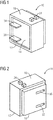
- Fig. 1 shows an ignition device module 10 according to the present invention in a perspective view onto a forefront 14 of a body 12 of the ignition device module 10.
- a primary voltage input terminal 20 is provided on the forefront 14 and is defined by two male connectors 34.
- two connectors of a secondary voltage output terminal 24 are provided.
- Within the body 12 means are provided to transform a primary voltage which is applied to the primary voltage input terminal 20 into a secondary voltage at the secondary voltage output terminal 24.
- the means can comprise a transformer (not shown) with a primary and a secondary winding used to increase the primary voltage to a higher value of the secondary voltage at the secondary voltage output terminal 24.
- Secondary voltage output terminal 24 can be connected to a spark generating means.
- the secondary voltage output terminal 24 (connected to the secondary winding of the transformer) can e.g. be connected to a spark electrode which is placed at a distance according to a spark gap from a grounded conduction element such that a spark is generated when the secondary voltage between the spark electrode and the grounded conducting element is sufficient to overcome the spark gap.
- a burner of the gas cooking appliance may be grounded and serve as the grounded element.
- the transformer inside the ignition device module 10 serves to increase the primary voltage applied to the primary voltage input terminal 20 to a secondary voltage applied to the secondary output voltage output terminal 24 of 5.000 - 10.000 Volt.
- Fig. 2 shows a view onto a backside 16 of the ignition device module 10 of Fig. 1 .
- a primary voltage output terminal 22 is defined by two female connectors 36. Both female connectors 36 are arranged at positions and have a cross-section so as to mate with the male connectors 34 on the forefront 14 of the ignition device module 10.
- the voltage at the primary voltage output terminal 22 is the same as applied to the primary voltage input terminal 20.
- each main connector 34 is in direct electrical connection with a respective female connector 36 as it will be described in further detail with reference to Fig. 3 .
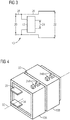
- Fig. 3 shows a wiring pattern of an ignition device module 10 according to the present invention, such as the ignition device module 10 of Figs. 1, 2 and 4 .
- the primary voltage input terminal 20 is illustrated.
- the primary voltage output terminal 22 is shown.
- feedthrough line 26 From feedthrough line 26 a feed-in line 28 branches and is connected to a transformer 38 located inside body 12 of the ignition device module 10 of Fig. 1 .
- Transformer 38 transforms the primary voltage of primary voltage input terminal 20 into the secondary voltage and applies the secondary voltage to secondary voltage output terminal 24.
- Feed-in line 28 is connected to a primary winding of transformer 38 and secondary voltage output terminal 24 to a secondary winding of transformer 38.
- the combined ignition device comprising the two ignition device modules 24A and 24B can be connected to a source of electrical power by means of the primary voltage input terminal 20 of ignition device module 10A.
- ignition device modules having different number of secondary voltage output terminals 24 can be combined provided that respective male and female connectors 34 are still mating. Therefore any desired number of secondary voltage output terminals 24 can be reached by plugging a respective number of respective types (defined by the number of secondary voltage output terminals 24) together. This leads to a modularity of the present inventive concept.
- the ignition device module 10 comprises a housing with a bottom portion. From said bottom portion, a pin-like connection mean 44 protrudes based on which said ignition device module 10 is coupled with said mechanical structure 42. Said connection mean 44 may be configured to be inserted in an opening 46 provided in said mechanical structure 42. Preferably, said connection mean 44 may be adapted to penetrate the mechanical structure 42.
- connection mean 44 comprise a pin portion and locking means adapted to prevent an undesired loosing of the ignition device module 10 from said mechanical structure 42.
- Said locking means may comprise one or more lock portions radially protruding from said pin portion. Said lock portions are dimensioned such that the said lock portions engage behind the edge of the opening 46.
- Fig. 7 shows a further embodiment of connection means 44 for securing the ignition device module 10 at the mechanical structure 42.
- the ignition device module 10 comprises connection means 44 in form of a mushroom-shaped pin.
- the mushroom-shaped pin is provided at a bottom portion of the ignition device module 10 and protrudes from said bottom portion.
- Said mushroom-shaped pin is adapted to interact with a keyhole-shaped opening 46 provided in the mechanical structure 42.
- Said keyhole-shaped opening 46 comprises a first opening portion 46.1 with first opening dimensions and a second opening portion 46.2 with second opening dimensions.
- Said second opening portion 46.2 may be a slot-like opening portion adjoining immediately at said first opening portion 46.1 and may radially protrude from said first opening portion 46.1.
- Said first opening dimensions may be grater than said second opening dimensions. More in detail, said first opening dimensions may be chosen such that said mushroom-shaped pin can be inserted in said opening 46. After inserting, the mushroom-shaped pin can be moved into said second opening portion 46.2 thereby obtaining an interlocking of the mushroom-shaped pin at the mechanical structure 42.
- securing the ignition device module 10 at the mechanical structure 42 may be possible, e.g. securing the ignition device module 10 at the mechanical structure 42 based on a screw connection.
- the housing of the ignition device module 10 may comprise an opening with a thread for receiving a free end of a screw based on which said securing of the ignition device module 10 at the mechanical structure 42 is obtained.
Landscapes
- Engineering & Computer Science (AREA)
- Chemical & Material Sciences (AREA)
- Combustion & Propulsion (AREA)
- Mechanical Engineering (AREA)
- General Engineering & Computer Science (AREA)
- Power Engineering (AREA)
- Ignition Installations For Internal Combustion Engines (AREA)
- Portable Nailing Machines And Staplers (AREA)
- Spark Plugs (AREA)
Claims (20)
- Zündvorrichtung für ein Gaskochgerät, wobei die Zündvorrichtung mindestens ein Zündvorrichtungsmodul (10, 10A, 10B) mit einer Primärspannungs-Eingangsklemme (20), einem Transformator (38) und mindestens einer Sekundärspannungs-Ausgangsklemme (24, 24A, 24B) aufweist, wobei der Transformator geeignet ist, eine an die Primärspannungs-Eingangsklemme angelegte Primärspannung in eine Sekundärspannung an der Sekundärspannungs-Ausgangsklemme umzuwandeln, und die Sekundärspannungs-Ausgangsklemme geeignet ist, mit einer Funkenelektrode verbunden zu werden,
dadurch gekennzeichnet, dass:
das Zündvorrichtungsmodul (10, 10A, 10B) weiterhin eine Primärspannungsausgangsklemme (22) umfasst. - Zündvorrichtung nach Anspruch 1, wobei die Zündvorrichtung eine Mehrzahl von Zündvorrichtungsmodulen (10A, 10B) umfasst, wobei
die Primärspannungs-Eingangsklemme (20) eines ersten Zündvorrichtungsmoduls (10A) dazu ausgebildet ist, mit einer Stromversorgung verbunden zu werden, und
der Primärspannungseingangsanschluss (20) eines nachfolgenden Zündvorrichtungsmoduls (10B) mit dem Primärspannungsausgangsanschluss des vorhergehenden Zündvorrichtungsmoduls (10A) verbunden ist. - Die Zündvorrichtung nach einem der vorhergehenden Ansprüche, wobei die Zündvorrichtung eine Vielzahl von Zündvorrichtungsmodulen (10, 10A, 10B) umfasst, wobei der Primärspannungs-Eingangsanschluss (20) eines ersten Zündvorrichtungsmoduls (10A) angepasst ist, um mit einer Energieversorgung verbunden zu werden, und wobei die Zündvorrichtungsmodule (10, 10A, 10B) parallel geschaltet sind, indem der Primärspannungs-Ausgangsanschluss (22) jedes vorhergehenden Zündvorrichtungsmoduls mit einem Primärspannungs-Eingangsanschluss (20) eines nachfolgenden Zündvorrichtungsmoduls verbunden ist.
- Die Zündvorrichtung nach einem der vorhergehenden Ansprüche, wobei die Zündvorrichtung eine Vielzahl von Zündvorrichtungsmodulen (10, 10A, 10B) umfasst, wobei die Zündvorrichtungsmodule zusammengesteckt sind und jeder Primärspannungseingangsanschluss (20) eines nachfolgenden Zündvorrichtungsmoduls (10B) mit dem Primärspannungsausgangsanschluss (22) des vorhergehenden Zündvorrichtungsmoduls (10A) verbunden ist.
- Zündvorrichtung nach einem der vorhergehenden Ansprüche, wobei das Zündvorrichtungsmodul (10, 10A, 10B) oder jedes Zündvorrichtungsmodul (10, 10A, 10B) mehrere, vorzugsweise zwei Sekundärspannungsausgangsklemmen (24) aufweist.
- Die Zündvorrichtung nach einem der vorhergehenden Ansprüche, wobei die Zündvorrichtung eine Mehrzahl von Zündvorrichtungsmodulen (10, 10A, 10B) umfasst und wobei die Primärspannungseingangsklemme (20) eines nachfolgenden Zündvorrichtungsmoduls (10B) in eine Primärspannungsausgangsklemme (22) eines vorhergehenden Zündvorrichtungsmoduls (10A) eingesteckt ist.
- Zündvorrichtung nach Anspruch 6, wobei die Zündentstörungsmodule (10, 10A, 10B) entlang einer Achse (32) aufeinanderfolgend angeordnet sind, wobei die Primärspannungseingangsklemmen (20) und die Primärspannungsausgangsklemmen (22) zusammenpassende männliche und weibliche Verbinder (34, 36) definieren, wobei die männlichen Verbinder (34) entlang der Achse ausgerichtet sind und angepasst sind, um von den weiblichen Verbindern (36) aufgenommen zu werden.
- Zündvorrichtung nach Anspruch 7, wobei die männlichen Steckverbinder (34) an einer Vorderseite (14) eines Körpers (12) der Zündvorrichtungsmodule (10, 10A, 10B) und die weiblichen Steckverbinder (36) an einer Rückseite (16) des Körpers oder umgekehrt angeordnet sind.
- Zündeinrichtung nach Anspruch 7 oder 8, wobei jeder sekundäre Spannungsausgangsanschluss (24) an einer lateralen Seite (18) des zugeordneten Zündeinrichtungsmoduls angeordnet ist.
- Zündvorrichtung nach einem der Ansprüche 2 bis 9, wobei jedes Zündvorrichtungsmodul (10, 10A, 10B) passende mechanische Verbindungsmittel aufweist, die geeignet sind, eine formschlüssige Verbindung zwischen zwei aufeinanderfolgenden Zündvorrichtungsmodulen zu ermöglichen.
- Zündvorrichtung nach Anspruch 10, wobei die mechanischen Verbindungsmittel einen oder mehrere Schnapphaken (31) umfassen, wobei die Schnapphaken (31) dazu geeignet sind, eine lösbare Verriegelung von aufeinanderfolgenden Zündvorrichtungsmodulen (10A, 10B) bereitzustellen.
- Zündvorrichtung nach einem der vorhergehenden Ansprüche, wobei ein Gehäuse des Zündvorrichtungsmoduls (10A, 10B) Verbindungsmittel (44) zum Verbinden des Zündvorrichtungsmoduls (10A, 10B) mit einer umgebenden mechanischen Struktur (42) umfasst.
- Zündvorrichtung nach Anspruch 12, wobei die Verbindungsmittel (44) einen Vorsprung, der so konfiguriert ist, dass er in eine entsprechende Öffnung (46) der umgebenden mechanischen Struktur (42) eingesetzt werden kann, oder ein Loch mit einem Gewinde zum Bereitstellen einer Schraubverbindung zwischen dem Gehäuse des Zündvorrichtungsmoduls (10A, 10B) und der umgebenden mechanischen Struktur (42) umfassen.
- Zündvorrichtung nach einem der Ansprüche 2 bis 13, wobei alle Zündvorrichtungsmodule (10, 10A, 10B) identisch sind.
- Zündvorrichtung nach einem der Ansprüche 2 bis 13, wobei mindestens zwei Zündvorrichtungsmodule (10, 10A, 10B) eine unterschiedliche Anzahl von Sekundärspannungsausgangsanschlüssen (24, 24A, 24B) aufweisen.
- Zündvorrichtung nach einem der vorhergehenden Ansprüche, wobei jedes Zündvorrichtungsmodul (10, 10A, 10B) eine Leiterplatte (PCB) umfasst, die den Transformator trägt.
- Die Zündvorrichtung nach einem der vorhergehenden Ansprüche, wobei eine an die Primärspannungs-Eingangsklemme (20) angelegte Primärspannung durch das Zündvorrichtungsmodul (10, 10A, 10B) zur Primärspannungs-Ausgangsklemme (22) geführt wird, so dass die Spannung an der Primärspannungs-Eingangsklemme dieselbe ist wie an der Primärspannungs-Ausgangsklemme.
- Die Zündvorrichtung nach einem der vorhergehenden Ansprüche, wobei die Primärspannung eine Wechselspannung von 100-240 V bei 50-60Hz, vorzugsweise 230V bei 50Hz ist.
- Gasgerät mit einer Zündvorrichtung nach einem der vorangehenden Ansprüche.
- Verfahren zum Zusammenbau eines Gasgeräts, wobei das Verfahren die folgenden Schritte umfasst:Bereitstellen von zwei oder mehr Zündvorrichtungsmodulen (10, 10A, 10B);Verbinden eines Primärspannungseingangsanschlusses (20) eines ersten Zündvorrichtungsmoduls (10A) mit einer Stromversorgung;gekennzeichnet durchVerbinden eines Primärspannungseingangsanschlusses (20) eines zweiten Zündvorrichtungsmoduls (10B) mit einem Primärspannungs-ausgangsanschluss des ersten Zündvorrichtungsmoduls (10A).
Applications Claiming Priority (2)
| Application Number | Priority Date | Filing Date | Title |
|---|---|---|---|
| EP17183777.6A EP3434977B1 (de) | 2017-07-28 | 2017-07-28 | Zündvorrichtung für einen gaskocher |
| PCT/EP2018/069325 WO2019020426A1 (en) | 2017-07-28 | 2018-07-16 | IGNITION DEVICE FOR GAS COOKING APPARATUS |
Publications (2)
| Publication Number | Publication Date |
|---|---|
| EP3658823A1 EP3658823A1 (de) | 2020-06-03 |
| EP3658823B1 true EP3658823B1 (de) | 2021-04-28 |
Family
ID=59501282
Family Applications (2)
| Application Number | Title | Priority Date | Filing Date |
|---|---|---|---|
| EP17183777.6A Active EP3434977B1 (de) | 2017-07-28 | 2017-07-28 | Zündvorrichtung für einen gaskocher |
| EP18740601.2A Active EP3658823B1 (de) | 2017-07-28 | 2018-07-16 | Zündvorrichtung für einen gaskocher |
Family Applications Before (1)
| Application Number | Title | Priority Date | Filing Date |
|---|---|---|---|
| EP17183777.6A Active EP3434977B1 (de) | 2017-07-28 | 2017-07-28 | Zündvorrichtung für einen gaskocher |
Country Status (6)
| Country | Link |
|---|---|
| US (1) | US10876734B2 (de) |
| EP (2) | EP3434977B1 (de) |
| CN (1) | CN110945287A (de) |
| AU (1) | AU2018308818B2 (de) |
| ES (2) | ES2816100T3 (de) |
| WO (1) | WO2019020426A1 (de) |
Families Citing this family (3)
| Publication number | Priority date | Publication date | Assignee | Title |
|---|---|---|---|---|
| US11908618B2 (en) | 2019-12-19 | 2024-02-20 | Orkli, S. Coop. | Thermoelectric assembly for powering electromagnetic valves of a cooking appliance |
| EP4062104A4 (de) * | 2020-01-22 | 2023-09-27 | Ferel Elektronik San. Ve Tic. A.S. | Zündvorrichtung mit isolationskörper für einen gaskocher |
| WO2023224569A1 (en) * | 2022-01-24 | 2023-11-23 | Mamur Teknoloji Sistemleri San. A.S. | Gas hob with an ignition unit |
Family Cites Families (8)
| Publication number | Priority date | Publication date | Assignee | Title |
|---|---|---|---|---|
| US5170768A (en) * | 1991-12-23 | 1992-12-15 | Ford Motor Company | Modular twin tower distributorless ignition coil |
| FR2710969B1 (fr) * | 1993-10-07 | 1995-12-15 | Sourdillon Sa | Faisceau électrique pour le câblage du circuit d'allumage électrique d'un appareil de cuisson à brûleurs à gaz. |
| ITTO20020921A1 (it) * | 2002-10-22 | 2004-04-23 | Itw Ind Components Srl | Dispositivo accendigas elettrico. |
| JP2004347312A (ja) | 2003-02-13 | 2004-12-09 | Ngk Spark Plug Co Ltd | 燃焼器具用放電点火装置 |
| TR200500747A1 (tr) * | 2005-03-04 | 2006-10-26 | Amaç Elektroni̇k Gaz Ateşleme Si̇stemleri̇ San. Ve Ti̇c. Ltd. Şti̇. | Soketli kapakta bütünleştirilmiş gaz ateşleme cihazı. |
| ITTO20060502A1 (it) | 2006-07-10 | 2008-01-11 | Itw Ind Components Srl | Dispositivo di accensione di fuochi in un elettrodomestico, in particolare un piano cottura o barbecue |
| ITTO20070215A1 (it) * | 2007-03-26 | 2008-09-27 | Itw Ind Components S R L Co N | Dispositivo accendigas compatto per un elettrodomestico, in particolare un piano di cottura |
| CN101814824B (zh) | 2010-04-02 | 2012-07-04 | 天津市东文高压电源厂 | 一种小型高压点火模块电源 |
-
2017
- 2017-07-28 EP EP17183777.6A patent/EP3434977B1/de active Active
- 2017-07-28 ES ES17183777T patent/ES2816100T3/es active Active
-
2018
- 2018-07-16 ES ES18740601T patent/ES2880074T3/es active Active
- 2018-07-16 WO PCT/EP2018/069325 patent/WO2019020426A1/en not_active Ceased
- 2018-07-16 AU AU2018308818A patent/AU2018308818B2/en active Active
- 2018-07-16 CN CN201880045714.0A patent/CN110945287A/zh active Pending
- 2018-07-16 EP EP18740601.2A patent/EP3658823B1/de active Active
- 2018-07-16 US US16/626,758 patent/US10876734B2/en active Active
Non-Patent Citations (1)
| Title |
|---|
| None * |
Also Published As
| Publication number | Publication date |
|---|---|
| WO2019020426A1 (en) | 2019-01-31 |
| CN110945287A (zh) | 2020-03-31 |
| EP3434977A1 (de) | 2019-01-30 |
| AU2018308818B2 (en) | 2024-01-18 |
| ES2880074T3 (es) | 2021-11-23 |
| US10876734B2 (en) | 2020-12-29 |
| BR112020001745A2 (pt) | 2020-07-21 |
| EP3434977B1 (de) | 2020-06-24 |
| EP3658823A1 (de) | 2020-06-03 |
| US20200124289A1 (en) | 2020-04-23 |
| ES2816100T3 (es) | 2021-03-31 |
| AU2018308818A1 (en) | 2020-01-16 |
Similar Documents
| Publication | Publication Date | Title |
|---|---|---|
| US4272689A (en) | Flexible wiring system and components therefor | |
| US6688894B2 (en) | Umbilical cable assembly | |
| US8814578B2 (en) | Modular connectors with easy-connect capability | |
| US6994595B2 (en) | Finger proof, keyed power connector and methods thereof | |
| AU2010258783B2 (en) | Dual column gang outlets for minimizing installation space | |
| CN105706305B (zh) | 用于异形安装轨的桥接模块 | |
| EP3658823B1 (de) | Zündvorrichtung für einen gaskocher | |
| US11139609B2 (en) | Modular connector for circuit boards | |
| CA2363529A1 (en) | Press-fit bus bar for distributing power | |
| US6394856B1 (en) | Electrical connector with programmable keying | |
| EP3769379B1 (de) | Verteiler von elektrischer energie zwischen verbindern | |
| US11817642B2 (en) | Modular plug connector for a printed circuit board | |
| CN111448532A (zh) | 具有印制电路板的电子设备 | |
| US11881662B2 (en) | 8+2 way XLR PCB female connector | |
| US8206179B2 (en) | Modular connector system | |
| US6435916B1 (en) | Electrical power connector for printed circuit boards | |
| KR200450463Y1 (ko) | 양방향 수커넥터 | |
| CN107006118B (zh) | 电气设备 | |
| US11901688B2 (en) | Adapter housing for a contact insert for fixing on a top-hat rail | |
| BR112020001745B1 (pt) | Dispositivo de ignição para um aparelho de cozimento a gás | |
| DK1515402T3 (en) | Electrical mounting device for buildings | |
| US20260005454A1 (en) | Multi-directional terminal block and method of making | |
| US20180337494A1 (en) | Electric power distribution module and system | |
| TW202243346A (zh) | 電源插座模組、電源插座連接器組及雙部件電耦接系統 |
Legal Events
| Date | Code | Title | Description |
|---|---|---|---|
| STAA | Information on the status of an ep patent application or granted ep patent |
Free format text: STATUS: UNKNOWN |
|
| STAA | Information on the status of an ep patent application or granted ep patent |
Free format text: STATUS: THE INTERNATIONAL PUBLICATION HAS BEEN MADE |
|
| PUAI | Public reference made under article 153(3) epc to a published international application that has entered the european phase |
Free format text: ORIGINAL CODE: 0009012 |
|
| STAA | Information on the status of an ep patent application or granted ep patent |
Free format text: STATUS: REQUEST FOR EXAMINATION WAS MADE |
|
| 17P | Request for examination filed |
Effective date: 20200228 |
|
| AK | Designated contracting states |
Kind code of ref document: A1 Designated state(s): AL AT BE BG CH CY CZ DE DK EE ES FI FR GB GR HR HU IE IS IT LI LT LU LV MC MK MT NL NO PL PT RO RS SE SI SK SM TR |
|
| AX | Request for extension of the european patent |
Extension state: BA ME |
|
| DAV | Request for validation of the european patent (deleted) | ||
| DAX | Request for extension of the european patent (deleted) | ||
| GRAP | Despatch of communication of intention to grant a patent |
Free format text: ORIGINAL CODE: EPIDOSNIGR1 |
|
| STAA | Information on the status of an ep patent application or granted ep patent |
Free format text: STATUS: GRANT OF PATENT IS INTENDED |
|
| INTG | Intention to grant announced |
Effective date: 20201210 |
|
| GRAS | Grant fee paid |
Free format text: ORIGINAL CODE: EPIDOSNIGR3 |
|
| GRAA | (expected) grant |
Free format text: ORIGINAL CODE: 0009210 |
|
| STAA | Information on the status of an ep patent application or granted ep patent |
Free format text: STATUS: THE PATENT HAS BEEN GRANTED |
|
| AK | Designated contracting states |
Kind code of ref document: B1 Designated state(s): AL AT BE BG CH CY CZ DE DK EE ES FI FR GB GR HR HU IE IS IT LI LT LU LV MC MK MT NL NO PL PT RO RS SE SI SK SM TR |
|
| REG | Reference to a national code |
Ref country code: GB Ref legal event code: FG4D |
|
| REG | Reference to a national code |
Ref country code: CH Ref legal event code: EP |
|
| REG | Reference to a national code |
Ref country code: AT Ref legal event code: REF Ref document number: 1387464 Country of ref document: AT Kind code of ref document: T Effective date: 20210515 |
|
| REG | Reference to a national code |
Ref country code: DE Ref legal event code: R096 Ref document number: 602018016292 Country of ref document: DE |
|
| REG | Reference to a national code |
Ref country code: IE Ref legal event code: FG4D |
|
| REG | Reference to a national code |
Ref country code: LT Ref legal event code: MG9D |
|
| REG | Reference to a national code |
Ref country code: AT Ref legal event code: MK05 Ref document number: 1387464 Country of ref document: AT Kind code of ref document: T Effective date: 20210428 |
|
| PG25 | Lapsed in a contracting state [announced via postgrant information from national office to epo] |
Ref country code: LT Free format text: LAPSE BECAUSE OF FAILURE TO SUBMIT A TRANSLATION OF THE DESCRIPTION OR TO PAY THE FEE WITHIN THE PRESCRIBED TIME-LIMIT Effective date: 20210428 Ref country code: HR Free format text: LAPSE BECAUSE OF FAILURE TO SUBMIT A TRANSLATION OF THE DESCRIPTION OR TO PAY THE FEE WITHIN THE PRESCRIBED TIME-LIMIT Effective date: 20210428 Ref country code: FI Free format text: LAPSE BECAUSE OF FAILURE TO SUBMIT A TRANSLATION OF THE DESCRIPTION OR TO PAY THE FEE WITHIN THE PRESCRIBED TIME-LIMIT Effective date: 20210428 Ref country code: NL Free format text: LAPSE BECAUSE OF FAILURE TO SUBMIT A TRANSLATION OF THE DESCRIPTION OR TO PAY THE FEE WITHIN THE PRESCRIBED TIME-LIMIT Effective date: 20210428 Ref country code: AT Free format text: LAPSE BECAUSE OF FAILURE TO SUBMIT A TRANSLATION OF THE DESCRIPTION OR TO PAY THE FEE WITHIN THE PRESCRIBED TIME-LIMIT Effective date: 20210428 Ref country code: BG Free format text: LAPSE BECAUSE OF FAILURE TO SUBMIT A TRANSLATION OF THE DESCRIPTION OR TO PAY THE FEE WITHIN THE PRESCRIBED TIME-LIMIT Effective date: 20210728 |
|
| REG | Reference to a national code |
Ref country code: ES Ref legal event code: FG2A Ref document number: 2880074 Country of ref document: ES Kind code of ref document: T3 Effective date: 20211123 |
|
| PG25 | Lapsed in a contracting state [announced via postgrant information from national office to epo] |
Ref country code: SE Free format text: LAPSE BECAUSE OF FAILURE TO SUBMIT A TRANSLATION OF THE DESCRIPTION OR TO PAY THE FEE WITHIN THE PRESCRIBED TIME-LIMIT Effective date: 20210428 Ref country code: RS Free format text: LAPSE BECAUSE OF FAILURE TO SUBMIT A TRANSLATION OF THE DESCRIPTION OR TO PAY THE FEE WITHIN THE PRESCRIBED TIME-LIMIT Effective date: 20210428 Ref country code: PT Free format text: LAPSE BECAUSE OF FAILURE TO SUBMIT A TRANSLATION OF THE DESCRIPTION OR TO PAY THE FEE WITHIN THE PRESCRIBED TIME-LIMIT Effective date: 20210830 Ref country code: PL Free format text: LAPSE BECAUSE OF FAILURE TO SUBMIT A TRANSLATION OF THE DESCRIPTION OR TO PAY THE FEE WITHIN THE PRESCRIBED TIME-LIMIT Effective date: 20210428 Ref country code: NO Free format text: LAPSE BECAUSE OF FAILURE TO SUBMIT A TRANSLATION OF THE DESCRIPTION OR TO PAY THE FEE WITHIN THE PRESCRIBED TIME-LIMIT Effective date: 20210728 Ref country code: LV Free format text: LAPSE BECAUSE OF FAILURE TO SUBMIT A TRANSLATION OF THE DESCRIPTION OR TO PAY THE FEE WITHIN THE PRESCRIBED TIME-LIMIT Effective date: 20210428 Ref country code: GR Free format text: LAPSE BECAUSE OF FAILURE TO SUBMIT A TRANSLATION OF THE DESCRIPTION OR TO PAY THE FEE WITHIN THE PRESCRIBED TIME-LIMIT Effective date: 20210729 Ref country code: IS Free format text: LAPSE BECAUSE OF FAILURE TO SUBMIT A TRANSLATION OF THE DESCRIPTION OR TO PAY THE FEE WITHIN THE PRESCRIBED TIME-LIMIT Effective date: 20210828 |
|
| REG | Reference to a national code |
Ref country code: NL Ref legal event code: MP Effective date: 20210428 |
|
| PG25 | Lapsed in a contracting state [announced via postgrant information from national office to epo] |
Ref country code: EE Free format text: LAPSE BECAUSE OF FAILURE TO SUBMIT A TRANSLATION OF THE DESCRIPTION OR TO PAY THE FEE WITHIN THE PRESCRIBED TIME-LIMIT Effective date: 20210428 Ref country code: SK Free format text: LAPSE BECAUSE OF FAILURE TO SUBMIT A TRANSLATION OF THE DESCRIPTION OR TO PAY THE FEE WITHIN THE PRESCRIBED TIME-LIMIT Effective date: 20210428 Ref country code: RO Free format text: LAPSE BECAUSE OF FAILURE TO SUBMIT A TRANSLATION OF THE DESCRIPTION OR TO PAY THE FEE WITHIN THE PRESCRIBED TIME-LIMIT Effective date: 20210428 Ref country code: SM Free format text: LAPSE BECAUSE OF FAILURE TO SUBMIT A TRANSLATION OF THE DESCRIPTION OR TO PAY THE FEE WITHIN THE PRESCRIBED TIME-LIMIT Effective date: 20210428 Ref country code: CZ Free format text: LAPSE BECAUSE OF FAILURE TO SUBMIT A TRANSLATION OF THE DESCRIPTION OR TO PAY THE FEE WITHIN THE PRESCRIBED TIME-LIMIT Effective date: 20210428 Ref country code: DK Free format text: LAPSE BECAUSE OF FAILURE TO SUBMIT A TRANSLATION OF THE DESCRIPTION OR TO PAY THE FEE WITHIN THE PRESCRIBED TIME-LIMIT Effective date: 20210428 |
|
| REG | Reference to a national code |
Ref country code: DE Ref legal event code: R097 Ref document number: 602018016292 Country of ref document: DE |
|
| REG | Reference to a national code |
Ref country code: DE Ref legal event code: R119 Ref document number: 602018016292 Country of ref document: DE |
|
| REG | Reference to a national code |
Ref country code: CH Ref legal event code: PL |
|
| PLBE | No opposition filed within time limit |
Free format text: ORIGINAL CODE: 0009261 |
|
| STAA | Information on the status of an ep patent application or granted ep patent |
Free format text: STATUS: NO OPPOSITION FILED WITHIN TIME LIMIT |
|
| PG25 | Lapsed in a contracting state [announced via postgrant information from national office to epo] |
Ref country code: MC Free format text: LAPSE BECAUSE OF FAILURE TO SUBMIT A TRANSLATION OF THE DESCRIPTION OR TO PAY THE FEE WITHIN THE PRESCRIBED TIME-LIMIT Effective date: 20210428 |
|
| REG | Reference to a national code |
Ref country code: BE Ref legal event code: MM Effective date: 20210731 |
|
| 26N | No opposition filed |
Effective date: 20220131 |
|
| PG25 | Lapsed in a contracting state [announced via postgrant information from national office to epo] |
Ref country code: LI Free format text: LAPSE BECAUSE OF NON-PAYMENT OF DUE FEES Effective date: 20210731 Ref country code: DE Free format text: LAPSE BECAUSE OF NON-PAYMENT OF DUE FEES Effective date: 20220201 Ref country code: CH Free format text: LAPSE BECAUSE OF NON-PAYMENT OF DUE FEES Effective date: 20210731 |
|
| PG25 | Lapsed in a contracting state [announced via postgrant information from national office to epo] |
Ref country code: IS Free format text: LAPSE BECAUSE OF FAILURE TO SUBMIT A TRANSLATION OF THE DESCRIPTION OR TO PAY THE FEE WITHIN THE PRESCRIBED TIME-LIMIT Effective date: 20210828 Ref country code: LU Free format text: LAPSE BECAUSE OF NON-PAYMENT OF DUE FEES Effective date: 20210716 Ref country code: AL Free format text: LAPSE BECAUSE OF FAILURE TO SUBMIT A TRANSLATION OF THE DESCRIPTION OR TO PAY THE FEE WITHIN THE PRESCRIBED TIME-LIMIT Effective date: 20210428 |
|
| PG25 | Lapsed in a contracting state [announced via postgrant information from national office to epo] |
Ref country code: IE Free format text: LAPSE BECAUSE OF NON-PAYMENT OF DUE FEES Effective date: 20210716 Ref country code: BE Free format text: LAPSE BECAUSE OF NON-PAYMENT OF DUE FEES Effective date: 20210731 |
|
| PGFP | Annual fee paid to national office [announced via postgrant information from national office to epo] |
Ref country code: ES Payment date: 20220928 Year of fee payment: 5 |
|
| PGFP | Annual fee paid to national office [announced via postgrant information from national office to epo] |
Ref country code: FR Payment date: 20220720 Year of fee payment: 5 |
|
| PG25 | Lapsed in a contracting state [announced via postgrant information from national office to epo] |
Ref country code: CY Free format text: LAPSE BECAUSE OF FAILURE TO SUBMIT A TRANSLATION OF THE DESCRIPTION OR TO PAY THE FEE WITHIN THE PRESCRIBED TIME-LIMIT Effective date: 20210428 |
|
| PG25 | Lapsed in a contracting state [announced via postgrant information from national office to epo] |
Ref country code: HU Free format text: LAPSE BECAUSE OF FAILURE TO SUBMIT A TRANSLATION OF THE DESCRIPTION OR TO PAY THE FEE WITHIN THE PRESCRIBED TIME-LIMIT; INVALID AB INITIO Effective date: 20180716 |
|
| P01 | Opt-out of the competence of the unified patent court (upc) registered |
Effective date: 20230625 |
|
| PG25 | Lapsed in a contracting state [announced via postgrant information from national office to epo] |
Ref country code: MK Free format text: LAPSE BECAUSE OF FAILURE TO SUBMIT A TRANSLATION OF THE DESCRIPTION OR TO PAY THE FEE WITHIN THE PRESCRIBED TIME-LIMIT Effective date: 20210428 |
|
| PG25 | Lapsed in a contracting state [announced via postgrant information from national office to epo] |
Ref country code: FR Free format text: LAPSE BECAUSE OF NON-PAYMENT OF DUE FEES Effective date: 20230731 |
|
| REG | Reference to a national code |
Ref country code: ES Ref legal event code: FD2A Effective date: 20240827 |
|
| PG25 | Lapsed in a contracting state [announced via postgrant information from national office to epo] |
Ref country code: MT Free format text: LAPSE BECAUSE OF FAILURE TO SUBMIT A TRANSLATION OF THE DESCRIPTION OR TO PAY THE FEE WITHIN THE PRESCRIBED TIME-LIMIT Effective date: 20210428 |
|
| PG25 | Lapsed in a contracting state [announced via postgrant information from national office to epo] |
Ref country code: ES Free format text: LAPSE BECAUSE OF NON-PAYMENT OF DUE FEES Effective date: 20230717 |
|
| PG25 | Lapsed in a contracting state [announced via postgrant information from national office to epo] |
Ref country code: ES Free format text: LAPSE BECAUSE OF NON-PAYMENT OF DUE FEES Effective date: 20230717 |
|
| PGFP | Annual fee paid to national office [announced via postgrant information from national office to epo] |
Ref country code: IT Payment date: 20250721 Year of fee payment: 8 |
|
| PGFP | Annual fee paid to national office [announced via postgrant information from national office to epo] |
Ref country code: GB Payment date: 20250722 Year of fee payment: 8 |
|
| PG25 | Lapsed in a contracting state [announced via postgrant information from national office to epo] |
Ref country code: TR Free format text: LAPSE BECAUSE OF FAILURE TO SUBMIT A TRANSLATION OF THE DESCRIPTION OR TO PAY THE FEE WITHIN THE PRESCRIBED TIME-LIMIT Effective date: 20210428 |