EP3657978B1 - Dispositif de distribution et d'application d'un produit cosmétique ou de soin - Google Patents
Dispositif de distribution et d'application d'un produit cosmétique ou de soin Download PDFInfo
- Publication number
- EP3657978B1 EP3657978B1 EP18752587.8A EP18752587A EP3657978B1 EP 3657978 B1 EP3657978 B1 EP 3657978B1 EP 18752587 A EP18752587 A EP 18752587A EP 3657978 B1 EP3657978 B1 EP 3657978B1
- Authority
- EP
- European Patent Office
- Prior art keywords
- rotary body
- barrel
- ring
- cylinder
- bored cylinder
- Prior art date
- Legal status (The legal status is an assumption and is not a legal conclusion. Google has not performed a legal analysis and makes no representation as to the accuracy of the status listed.)
- Active
Links
- 239000002537 cosmetic Substances 0.000 title claims description 24
- 230000007246 mechanism Effects 0.000 claims description 9
- 239000012530 fluid Substances 0.000 claims description 8
- 235000011837 pasties Nutrition 0.000 claims description 5
- 239000007788 liquid Substances 0.000 claims description 4
- 230000001131 transforming effect Effects 0.000 claims description 4
- 230000002093 peripheral effect Effects 0.000 claims description 3
- 238000007789 sealing Methods 0.000 claims description 2
- 230000009172 bursting Effects 0.000 description 2
- 230000009466 transformation Effects 0.000 description 2
- 241000282346 Meles meles Species 0.000 description 1
- 241001465754 Metazoa Species 0.000 description 1
- 239000011324 bead Substances 0.000 description 1
- 239000000470 constituent Substances 0.000 description 1
- 238000001035 drying Methods 0.000 description 1
- 230000000694 effects Effects 0.000 description 1
- 239000000203 mixture Substances 0.000 description 1
- 238000000465 moulding Methods 0.000 description 1
- 230000007170 pathology Effects 0.000 description 1
- 230000000149 penetrating effect Effects 0.000 description 1
- 230000035515 penetration Effects 0.000 description 1
- 230000000750 progressive effect Effects 0.000 description 1
- 239000008257 shaving cream Substances 0.000 description 1
- 239000000344 soap Substances 0.000 description 1
- 230000000007 visual effect Effects 0.000 description 1
Images


Classifications
-
- A—HUMAN NECESSITIES
- A45—HAND OR TRAVELLING ARTICLES
- A45D—HAIRDRESSING OR SHAVING EQUIPMENT; EQUIPMENT FOR COSMETICS OR COSMETIC TREATMENTS, e.g. FOR MANICURING OR PEDICURING
- A45D34/00—Containers or accessories specially adapted for handling liquid toiletry or cosmetic substances, e.g. perfumes
- A45D34/04—Appliances specially adapted for applying liquid, e.g. using roller or ball
-
- A—HUMAN NECESSITIES
- A45—HAND OR TRAVELLING ARTICLES
- A45D—HAIRDRESSING OR SHAVING EQUIPMENT; EQUIPMENT FOR COSMETICS OR COSMETIC TREATMENTS, e.g. FOR MANICURING OR PEDICURING
- A45D40/00—Casings or accessories specially adapted for storing or handling solid or pasty toiletry or cosmetic substances, e.g. shaving soaps or lipsticks
- A45D40/02—Casings wherein movement of the lipstick or like solid is a sliding movement
- A45D40/04—Casings wherein movement of the lipstick or like solid is a sliding movement effected by a screw
-
- A—HUMAN NECESSITIES
- A45—HAND OR TRAVELLING ARTICLES
- A45D—HAIRDRESSING OR SHAVING EQUIPMENT; EQUIPMENT FOR COSMETICS OR COSMETIC TREATMENTS, e.g. FOR MANICURING OR PEDICURING
- A45D40/00—Casings or accessories specially adapted for storing or handling solid or pasty toiletry or cosmetic substances, e.g. shaving soaps or lipsticks
- A45D40/26—Appliances specially adapted for applying pasty paint, e.g. using roller, using a ball
- A45D40/262—Appliances specially adapted for applying pasty paint, e.g. using roller, using a ball using a brush or the like
- A45D40/265—Appliances specially adapted for applying pasty paint, e.g. using roller, using a ball using a brush or the like connected to the cap of the container
-
- A—HUMAN NECESSITIES
- A45—HAND OR TRAVELLING ARTICLES
- A45D—HAIRDRESSING OR SHAVING EQUIPMENT; EQUIPMENT FOR COSMETICS OR COSMETIC TREATMENTS, e.g. FOR MANICURING OR PEDICURING
- A45D40/00—Casings or accessories specially adapted for storing or handling solid or pasty toiletry or cosmetic substances, e.g. shaving soaps or lipsticks
- A45D2040/0006—Accessories
-
- A—HUMAN NECESSITIES
- A45—HAND OR TRAVELLING ARTICLES
- A45D—HAIRDRESSING OR SHAVING EQUIPMENT; EQUIPMENT FOR COSMETICS OR COSMETIC TREATMENTS, e.g. FOR MANICURING OR PEDICURING
- A45D2200/00—Details not otherwise provided for in A45D
- A45D2200/05—Details of containers
- A45D2200/053—Transparent containers
-
- A—HUMAN NECESSITIES
- A45—HAND OR TRAVELLING ARTICLES
- A45D—HAIRDRESSING OR SHAVING EQUIPMENT; EQUIPMENT FOR COSMETICS OR COSMETIC TREATMENTS, e.g. FOR MANICURING OR PEDICURING
- A45D2200/00—Details not otherwise provided for in A45D
- A45D2200/05—Details of containers
- A45D2200/054—Means for supplying liquid to the outlet of the container
- A45D2200/055—Piston or plunger for supplying the liquid to the applicator
Definitions
- the invention relates to the field of devices for dispensing and applying a cosmetic or care product.
- Cosmetic products encompass all products for making up the skin or integuments as well as all perfuming or fragrant compositions intended for body application.
- Care products include in particular those intended to be applied to the human or animal body to treat or prevent a pathology.
- the invention relates in particular to a device for dispensing and applying such a cosmetic or care product in liquid, semi-fluid or pasty form.
- the document US 2004/0084343 discloses a lipstick dispenser in which an endless screw actuates a movable piston in the hollow body of the device which forms a reservoir, in order to progressively reduce its volume to cause, opposite the piston, the controlled expulsion of the lipstick. Nevertheless, the disclosed mechanism is bulky longitudinally, making the dispenser itself bulky. In addition, it does not give any indication of the amount of product remaining in the dispenser.
- WO2012102427 a cosmetic product applicator making it possible to deliver a predefined quantity of product.
- Its structure has a main container inside which a sealed piston is moves on a threaded rod drilled longitudinally.
- the threaded rod is coupled to a rotary support which allows the piston to be driven in movement in the body of the container.
- This type of applicator in which the threaded rod is in contact with the cosmetic product, is sensitive to clogging which limits its use to certain cosmetic products (very fluid, not risking hardening or drying, etc. .), and prevents you from being able to recharge it.
- Another type of applicator is known from FR2639260 .
- the object of the invention is to provide a device for dispensing and applying a cosmetic or care product, suitable for liquid to pasty products, solving at least one of the aforementioned problems.
- the invention relates to a device for dispensing and applying a liquid, semi-fluid or pasty cosmetic or care product according to claim 1.
- the device comprises an elongated and hollow rotating body and an elongated outer barrel and hollow abutting one another, and movable in rotation with respect to one another.
- An application nozzle is fixed at the end of the rotating body,
- the rotating body and the outer barrel form an interior volume in which are formed a drilled cylinder comprising a longitudinal duct, and an interior barrel comprising an open end through which the cylinder is introduced. pierced and one end closed so as to form a reservoir for the cosmetic or care product.
- the drilled cylinder is fixed in translation with respect to the rotating body inside which it extends.
- the device comprises a mechanism for transforming a rotation of the rotating body relative to the outer barrel into a translational movement of the interior barrel vis-à-vis the cylinder pierced in the interior volume formed by said rotating body and exterior barrel.
- the transformation mechanism may include a threaded part integral with the inner barrel, and the assembly formed by the rotating body and the drilled cylinder may include a threaded part adapted to cooperate with the threaded part integral with the internal barrel so that the rotation of said body rotating causes the rotation of said threaded part and the translation of said threaded part and of the internal barrel along said threaded part, and corollary of the translation of the internal barrel with respect to the drilled cylinder.
- the device may further include a piston mounted fixedly at one end of the pierced cylinder introduced by the open end of the inner barrel, the piston comprising a peripheral surface whose contact with the interior surface of the inner barrel ensures a seal against the product, said piston comprising a central opening opening into the longitudinal duct of the drilled cylinder.
- the piston may include an elongated portion extending inside the longitudinal duct of the pierced cylinder.
- the device may further include a non-return valve positioned at the outlet of the longitudinal duct of the drilled cylinder.
- the threaded part is formed by or on the drilled cylinder, so that said drilled cylinder has a thread on its outer surface so as to form a screw, the threaded part being a ring forming a nut on said cylinder. perforated.
- the threaded portion may be formed by adding a hollow threaded rod to an exterior surface of the drilled cylinder.
- the device may include a sleeve in the rotating body, said sleeve being free to rotate with respect to said rotating body but fixed in rotation with respect to the outer barrel, said ring being inside the sleeve and said sleeve. and said ring being configured so that said ring can translate in the sleeve but remains fixed therein in rotation.
- the sleeve may comprise, on an internal face, at least one longitudinal groove, and the ring may comprise at least one notch in which said longitudinal groove is introduced so that the ring is guided in longitudinal translation in the sleeve on said longitudinal groove.
- the threaded part is formed by an inner surface of the rotating body having a thread, the threaded part being a ring having on at least part of its periphery a thread cooperating with the thread of the inner surface of the rotating body.
- the ring may comprise two threaded portions, diametrically opposed, projecting from the outer surface of the ring, and a longitudinal guide which extends inside the rotating body so as to guide said ring in longitudinal translation inside said ring. rotating body.
- the outer barrel can be transparent or translucent, or opaque.
- the inner barrel can be transparent or translucent, or opaque.
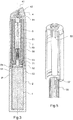
- the figure 1 shows a device according to one embodiment of the invention.
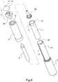
- the figure 2 also shows an exploded view of the device of the figure 1 , which details the constituent parts and allows to understand the assembly.
- This device is described below for the distribution and application of a cosmetic product, but can be used identically for the distribution and application of a care product.
- the device allows the distribution and application of a cosmetic product P, fluid, semi-fluid, or pasty.
- the cosmetic product P is contained in a reservoir called the inner barrel 1.
- the inner barrel 1 has the shape, in the example shown here, of a straight cylinder closed at one end and open at the other.
- the device comprises an outer barrel 2.
- the outer barrel 2 forms the lower part of the dispensing and application device. It is elongated in shape, and may have a cylindrical or prismatic outer shape.
- the outer barrel 2 comprises a bottom 21 which may include a closing wall. Nevertheless, the outer barrel advantageously comprises an air intake. This air intake can be provided through the bottom wall 21.
- the air intake allows air exchanges between the interior and the exterior of the outer barrel 2. It allows in particular the entry of air into the outer drum during the movement, described below, of the inner drum 1 in the outer drum 2 during the dispensing of product.
- the outer barrel 2 also has an open opposite face 22, into which the interior barrel 1 is introduced.
- the interior shape of the exterior barrel 2 corresponds to a clearance close to the external shape of the interior barrel 1. This allows longitudinal translation, or otherwise. said sliding along a main axis (A) of the device, of the inner barrel 1 in the outer barrel 2.
- the outer barrel 2 is advantageously transparent or translucent, which makes it possible to visualize the position of the inner barrel 1 in the device.
- the position of the inner barrel 1 in the device also corresponds to a quantity of product remaining given. In other words, visualizing the position of the inner barrel 1 allows the user to visualize the quantity of product remaining, or, conversely, the quantity of product consumed.
- the inner barrel 1 is itself transparent or translucent, the product is directly visible. This is aesthetically rewarding, and also allows the user to identify the desired product by its appearance, in particular its color, its shine, and / or its other visual characteristics.
- the device also comprises an element which forms its upper part and which is called the rotating body 3.
- the rotating body 3 is of elongated shape, and may have a cylindrical or prismatic outer shape, and in particular an outer shape corresponding to the outer shape of the barrel. lower 2.
- the rotating body 3 abuts the outer barrel 2.
- the rotating body 3 can be pivoted with respect to the latter around the main axis (A) of the device. Examples of connections that can be implemented between the rotating body 3 and the outer barrel 2 are described below with reference to figures 3 , 6 and 9 .
- the rotating body 3 is so designated because it constitutes the element that the user turns, relative to the outer barrel 2, in order to cause the dispensing of cosmetic product by the device.
- the rotating body 3 is hollow and thus defines, with the outer barrel 2 to which it is linked, an internal volume of the dispensing and application device.
- An applicator tip 4 is fixed at the end of the rotating body 3.
- the applicator tip 4 has an application surface 41, through which the cosmetic product P is distributed and which allows it to be applied, for example in a thin and regular layer. on the skin of the user of the device.
- the device comprises, in the interior volume formed by the rotating body 3 and the exterior barrel 2, on the one hand the interior barrel 1, but also a pierced cylinder 5.
- the pierced cylinder 5 comprises over its entire length, ie. that is to say along its axis of extension coincident with the main axis (A), a longitudinal duct 51.
- the longitudinal duct 51 has a constant or changing section.
- the drilled cylinder 5 is fixed in translation with respect to the rotating body 3, inside which he's stretching. According to the embodiment considered, the drilled cylinder 5 may be fixed or mobile in rotation with respect to the rotating body 3. In the embodiment of figures 1 to 6 , the drilled cylinder 5 is fixed in rotation with respect to the rotating body 3.
- the drilled cylinder 5 can either be fixed to the rotating body 3 directly or via an intermediate piece which can be the application nozzle 4, or else be formed integrally with the rotating body 3.
- the drilled cylinder 5 is introduced into the inner barrel 1 through its open end 22.
- the device comprises a mechanism for transforming a rotation of the rotating body 3 relative to the outer barrel 2 into a translational movement of the interior barrel 1 vis-à-vis the pierced cylinder 5.
- the interior barrel 1 which is movable, while the pierced cylinder 5 remains fixed longitudinally. Due to the movement of the inner barrel 1, the pierced cylinder penetrates more or less into said inner barrel, which causes it to vary the internal volume available for the storage of the cosmetic product P.
- a decrease in the volume available in the inner cylinder P results in an expulsion of a corresponding quantity of product P via the longitudinal duct 51 of the drilled cylinder 5.
- the movement transformation mechanism can have various configurations, two variations of which are detailed in support of the figures 3 to 6 on the one hand, and 7 to 10 on the other. These examples of mechanisms, as well as that of the figure 1 are based on a threaded part (having a female or male thread according to the considered variants of the invention) linked to the inner barrel 1, and on the fact that the assembly formed by the rotating body 3 and the drilled cylinder 5 comprises a part threaded (male or female depending on the variant considered) adapted to cooperate with the threaded part.
- the threaded part is a ring 71 having an internal thread, called a female thread.
- the ring 71 is fixed to the open end 22 of the inner barrel 1, which it obstructs except at the level of its threaded opening.
- the inner barrel 1 goes up along the drilled cylinder 5, which has the effect of reducing the interior volume available in the interior barrel 1 for the product P, and of causing the expulsion of a quantity of product P from the inner barrel 1 via the duct 51 of the drilled cylinder 5.
- the device may include, as is the case in the example shown in figure 1 , a cap or cover 8.
- the cover 8 makes it possible to close the device in order to prevent cosmetic product from being spilled, to protect the dispensing tip, and to prevent undesired actuation of the device.
- the cover 8 can also have an aesthetic role. It can carry a logo or an inscription.
- the figure 3 shows, in a cross-sectional view, a variant of the embodiment of the figures 1 and 2 .
- An exploded view of the alternative embodiment of the figure 3 is presented at the figure 4 .
- the operating kinematics of this variant is identical to that described above with reference to said figures 1 and 2 .
- the variant of the figure 4 differs from that presented to figures 1 and 2 essentially by the characteristics described below.
- a piston 52 is attached to the end of the drilled cylinder.
- the piston 52 has a central opening 53 which opens into the duct 51 of the pierced cylinder 5.
- the central opening 53 thus ensures fluid communication between a front surface 54 of the piston 52, which is in contact with the product P in the pierced cylinder. 5, and said duct 51.
- the piston 52 is configured so as to have a peripheral surface 55 in sealed contact with the inner wall 11 of the inner barrel 1.
- the piston 52 allows complete or almost complete expulsion of the product, the residual volume in the inner barrel 1 being zero or almost zero when said interior barrel is raised as far as possible in the device, and when the front face 54 of the piston 52 is in contact. or near the bottom of the inner barrel 1.
- the piston prevents the threaded part from coming into contact with cosmetic product when using the device. This prevents any fouling of said threaded part, and can, where appropriate, make it possible to refill the device with cosmetic product without it being necessary to clean the threaded part.
- the conduit 51 has, in the example shown, an evolving section.
- the duct 51 has a progressive restriction of its inlet (at its end introduced into the inner barrel 1) at its outlet.
- the evolution of the section, in particular its restriction, and / or a particular shape of the duct 51 can for example allow the destructuring of the formula and the bursting of beads comprising a fluid present in the product P (for example a lip gloss , to improve the gloss obtained), just before dispensing said product P.
- a non-return valve 91 is arranged between the outlet of the conduit 51 and the application nozzle 4.
- the non-return valve 91 protects the product P contained in the device. the outside atmosphere.
- the non-return valve 91 also makes it possible, to a certain extent, to prevent the rotating body from being actuated in the direction of rotation tending to suck product back into the inner barrel 1.
- the non-return valve contributes to the general sealing of the dispensing device when the latter is in the inverted position (application nozzle 4 facing downwards), for example in a user's handbag.
- the non-return valve 91 can also aid in the bursting of balls present, if any, in the product P.
- FIG. 1 Another difference between the device of figures 1 and 2 and that of figures 3 to 6 is the constitution of the threaded part of the drilled cylinder. While in the system of figures 1 and 2 , the drilled cylinder 5 and the threaded part are in one piece, in the variant of figures 3 to 6 the threaded part is formed by a hollow threaded rod 56 which is added to the drilled cylinder 5. In particular, the hollow threaded rod 56 forms a sleeve around the drilled cylinder 5, that is to say around the outer surface of the cylinder perforated.
- the hollow threaded rod 56 is provided, on a portion of its inner surface, with notches 57 of shape corresponding to that of lugs 58 carried by the drilled cylinder 5.
- the figure 6 represents a detailed view of the device figures 3 to 5 , near the junction between the lower part of the device comprising the outer barrel 2 and the upper part comprising in particular the drilled cylinder 5 and the rotating body 3 (not shown in Figure figure 6 ).
- connection between the outer barrel 2 and the rotating body 3 is made, in the example shown here, by an O-ring 92 inserted into grooves formed respectively on an interior surface of the rotating body 3 and on an exterior surface of the exterior barrel 2 .
- the piston 52 may include an oblong portion 521 inserted into the duct 5.
- the piston 52 is linked to the hollow cylinder 5 by means of a projection 522 of the internal surface of the duct 51 adapted to be clipped into a circular groove 523 of the oblong portion 521.
- the device comprises a sleeve 10, extending in the rotating body, which is fixed relative to the outer barrel 2 and which has guides in translation of the ring 71.
- the outer barrel 2 comprises in its upper part a notch 21 adapted to mesh with a corresponding toothing 101 of said sleeve, which blocks the sleeve in rotation vis-à-vis the outer barrel 2.
- the sleeve comprises on its internal surface longitudinal grooves 102, that is to say parallel to the main axis (A), along which the ring 71 is guided.
- the ring 71 may therefore have, on its periphery, notches 72 which slide on the longitudinal grooves 102.
- the device cover has been omitted at the figures 3 and 4 .
- the cover covers the application tip 4 and only a small end portion of the rotating body 3. .
- the figure 7 shows, in a schematic sectional view, an example of another embodiment of the invention.
- the figure 8 illustrates the device of the figure 7 according to an exploded view.
- the threaded portion of the assembly formed by the rotating body 3 and the drilled cylinder 5 is formed on an interior surface 31 of the rotating body 3, said interior surface 31 having a thread.
- the thread formed on the inner surface 31 is therefore a female thread.
- the threaded part is a ring 71 ′ rigidly linked to the inner shaft 1 or formed, as in the example shown here, integrally with said inner shaft 1.
- the ring 71 ′ comprises on part of its periphery a thread cooperating with the thread of the inner surface 31 of the rotating body 3. It is therefore a male thread, of corresponding diameter and of the same pitch.
- the ring 71 ′ is integral with and formed integrally, for example by molding, with the internal barrel 1. It comprises two threaded portions 73, formed in the upper part of the internal barrel 1, that is to say. ie at its open end.
- a longitudinal guide 23 is formed at the end of the outer shaft 2.
- the longitudinal guide extends inside the rotating body 3, in order to guide the rise of the internal barrel 1 in said rotating body 3.
- the longitudinal guide 23 has two longitudinal openings 24 in which the threaded portions 73 of the ring 71 ', which protrude from the rest of the ring, can slide.
- the device of figures 7 to 9 comprises a piston 52.
- the piston 52 allows in particular, as explained with reference to figures 3 to 6 , expulsion of all or almost all of the product P, and to avoid fouling of the threaded part when using the device.
- a base 43 of the application tip 4 is arranged at the end of the device and allows its assembly.
- the base 43 is adapted on the one hand to its clipping to the drilled cylinder 5, and to the guide means 23 of the outer barrel on the other hand.
- the base 43, and therefore more generally the end piece 4, as well as the drilled cylinder 5, remain fixed relative to the outer barrel 2 when the rotating body 3 is rotated in order to cause the translation of the interior barrel in the device.
- the base 43 also provides an end volume 44 adapted to receive the non-return valve 91.
- the base 43 is configured for fixing, for example by clipping, a cap 45 comprising the application surface 41.
- the application surface can have various shapes, depending on the type of product and the targeted application area.
- the application surface can be substantially conical, as in the example of figures 7 to 9 , or be substantially flat and inclined with respect to the main axis (A) of the device, as in the example of figures 3 to 6 , or be domed as in the example of figures 1 and 2 .
- the devices presented are in particular suitable for the application of a lip gloss, more commonly referred to by the English term “gloss”.
- the invention thus developed provides a cosmetic or care product applicator device allowing precise dosage of the quantity of product to be delivered (due to the dosage by rotation of a rotating body), and according to the variant of the invention considered, avoiding clogging of the distribution mechanism and / or indicating the quantity of product remaining and, conversely, consumed.
Landscapes
- Containers And Packaging Bodies Having A Special Means To Remove Contents (AREA)
- Closures For Containers (AREA)
Applications Claiming Priority (2)
| Application Number | Priority Date | Filing Date | Title |
|---|---|---|---|
| FR1757086A FR3069422B1 (fr) | 2017-07-26 | 2017-07-26 | Dispositif de distribution et d'application d'un produit cosmetique ou de soin |
| PCT/FR2018/051831 WO2019020907A1 (fr) | 2017-07-26 | 2018-07-18 | Dispositif de distribution et d'application d'un produit cosmétique ou de soin |
Publications (2)
| Publication Number | Publication Date |
|---|---|
| EP3657978A1 EP3657978A1 (fr) | 2020-06-03 |
| EP3657978B1 true EP3657978B1 (fr) | 2021-10-06 |
Family
ID=60080994
Family Applications (1)
| Application Number | Title | Priority Date | Filing Date |
|---|---|---|---|
| EP18752587.8A Active EP3657978B1 (fr) | 2017-07-26 | 2018-07-18 | Dispositif de distribution et d'application d'un produit cosmétique ou de soin |
Country Status (7)
| Country | Link |
|---|---|
| US (1) | US11076676B2 (ko) |
| EP (1) | EP3657978B1 (ko) |
| JP (1) | JP6945056B2 (ko) |
| KR (1) | KR102393712B1 (ko) |
| CN (1) | CN110996714B (ko) |
| FR (1) | FR3069422B1 (ko) |
| WO (1) | WO2019020907A1 (ko) |
Families Citing this family (3)
| Publication number | Priority date | Publication date | Assignee | Title |
|---|---|---|---|---|
| GB2586671B (en) * | 2020-02-18 | 2021-10-27 | Mr And Mrs Oliver Ltd | A substance dispenser and a method of providing a substance dispenser |
| CN114504181B (zh) * | 2020-11-16 | 2023-08-01 | 广东一芙化妆品有限公司 | 具备消毒功能的化妆品涂抹装置 |
| CN217791869U (zh) * | 2022-04-21 | 2022-11-15 | 洽兴包装工业(中国)有限公司 | 防锁死的塞杆组合及旋动出料容器 |
Family Cites Families (15)
| Publication number | Priority date | Publication date | Assignee | Title |
|---|---|---|---|---|
| US64732A (en) | 1867-05-14 | wylie | ||
| JPS5833108Y2 (ja) * | 1978-08-22 | 1983-07-23 | 株式会社吉野工業所 | カ−トリッジ式クリ−ム等注出容器 |
| FR2639260B1 (fr) * | 1988-11-18 | 1991-02-08 | Somater Conditionnements | Baton applicateur de produit pateux |
| FR2826841B1 (fr) * | 2001-07-03 | 2003-09-26 | Oreal | Dispositif de conditionnement et de distribution d'un produit, notamment un rouge a levres liquide |
| KR100444387B1 (ko) | 2001-08-16 | 2004-08-16 | 안석두 | 액형 립 펜슬의 용기 |
| DE20302008U1 (de) * | 2003-02-08 | 2003-04-10 | H & M Gutberlet Gmbh | Applikationsvorrichtung zum Auftragen eines flüssigen, gelartigen oder pastösen Kosmetikmediums auf die Haut |
| US7309184B2 (en) * | 2003-08-15 | 2007-12-18 | Revlon Consumer Products Corporation | Dispenser for fluid materials |
| US7878728B2 (en) * | 2004-08-17 | 2011-02-01 | Shiseido Co., Ltd. | Viscous cosmetic |
| KR100758216B1 (ko) * | 2005-10-11 | 2007-09-12 | 변영광 | 토출형 액상 화장품용기 |
| WO2012102427A1 (ko) * | 2011-01-28 | 2012-08-02 | Shin Ki Bong | 화장품용기 |
| KR101247124B1 (ko) * | 2011-08-31 | 2013-03-25 | (주)연우 | 펜슬형 화장품용기 |
| KR101486198B1 (ko) * | 2014-10-14 | 2015-02-11 | 김진우 | 회전 압출식 화장품 용기 |
| KR101524475B1 (ko) * | 2014-12-12 | 2015-06-01 | (주)연우 | 액상의 내용물이 함침된 흡수부재가 구비되는 화장품 용기 |
| KR20160124967A (ko) * | 2015-04-20 | 2016-10-31 | (주)아모레퍼시픽 | 회전 토출식 화장품 용기 |
| KR101744391B1 (ko) * | 2015-05-14 | 2017-06-12 | 주식회사 태성산업 | 스틱형 화운데이션 용기 |
-
2017
- 2017-07-26 FR FR1757086A patent/FR3069422B1/fr not_active Expired - Fee Related
-
2018
- 2018-07-18 WO PCT/FR2018/051831 patent/WO2019020907A1/fr unknown
- 2018-07-18 CN CN201880048260.2A patent/CN110996714B/zh active Active
- 2018-07-18 US US16/633,988 patent/US11076676B2/en active Active
- 2018-07-18 EP EP18752587.8A patent/EP3657978B1/fr active Active
- 2018-07-18 KR KR1020207005557A patent/KR102393712B1/ko active IP Right Grant
- 2018-07-18 JP JP2020503972A patent/JP6945056B2/ja active Active
Also Published As
| Publication number | Publication date |
|---|---|
| FR3069422A1 (fr) | 2019-02-01 |
| FR3069422B1 (fr) | 2021-07-16 |
| CN110996714B (zh) | 2022-11-29 |
| US11076676B2 (en) | 2021-08-03 |
| KR20200073201A (ko) | 2020-06-23 |
| US20200214421A1 (en) | 2020-07-09 |
| KR102393712B1 (ko) | 2022-05-02 |
| EP3657978A1 (fr) | 2020-06-03 |
| CN110996714A (zh) | 2020-04-10 |
| JP2020527994A (ja) | 2020-09-17 |
| WO2019020907A1 (fr) | 2019-01-31 |
| JP6945056B2 (ja) | 2021-10-06 |
Similar Documents
| Publication | Publication Date | Title |
|---|---|---|
| CA2115885C (fr) | Applicateur | |
| EP0161980B1 (fr) | Ensemble de maquillage, notamment pour les cils, permettant de prélever une quantité predeterminée de produit de maquillage | |
| EP3657978B1 (fr) | Dispositif de distribution et d'application d'un produit cosmétique ou de soin | |
| EP1208765B1 (fr) | Stick, notamment pour un produit sous forme d'une crème, d'un gel ou d'une pate | |
| FR2868669A1 (fr) | Dispositif de conditionnement et d'application d'un produit. | |
| EP1195103A1 (fr) | Applicateur et récipient muni d'un tel applicateur | |
| FR2979808A1 (fr) | Dispositif d'application de produit cosmetique avec un organe applicateur rotatif | |
| FR2727609A1 (fr) | Ensemble de distribution pour l'application d'un produit de consistance liquide a pateuse | |
| EP1410730B1 (fr) | Dispositif comportant un mécanisme d'entraínement d'un stick ou d'un piston mobile dans une partie de base | |
| FR2630712A1 (fr) | Recipient a dispositif distributeur pour produit liquide ou pateux | |
| EP1869995A1 (fr) | Ensemble de conditionnement et d'application d'un produit, notamment d'un produit cosmétique, et procédé d'application correspondant. | |
| FR3053222A1 (fr) | Systeme de conditionnement et de distribution d’un produit fluide, en particulier d’un produit cosmetique fluide | |
| FR2883139A1 (fr) | Dispositif de conditionnement et d'application d'un produit cosmetique | |
| FR2637512A1 (fr) | Dispositif de delivrance automatique d'un produit ou d'un objet quelconque | |
| EP1452109B1 (fr) | Dispositif d'application d'un produit, notamment cosmétique | |
| EP1842448A2 (fr) | Dispositif de conditionnement et d'application | |
| EP3654800B1 (fr) | Mecanisme de came, en particulier pour un applicateur de produit cosmetique | |
| EP2062496B1 (fr) | Système d'application d'un produit liquide pâteux avec applicateur rétractable | |
| FR3059529B1 (fr) | Applicateur de produit cosmetique fluide | |
| FR3042692A1 (fr) | Dispositif d'application pour produit cosmetique liquide | |
| FR2563712A1 (fr) | Ensemble de maquillage, notamment pour les cils, permettant de prelever une quantite predeterminee de produit de maquillage | |
| EP3855974A1 (fr) | Flacon comportant un applicateur à bille et un obturateur | |
| FR2825904A1 (fr) | Stick, notamment pour un produit sous forme d'une creme, d'un gel, ou d'une pate | |
| FR3021510A1 (fr) | Applicateur de produit cosmetique a pointe feutre | |
| FR2876557A1 (fr) | Stylo distributeur d'un produit cosmetique fluide |
Legal Events
| Date | Code | Title | Description |
|---|---|---|---|
| STAA | Information on the status of an ep patent application or granted ep patent |
Free format text: STATUS: UNKNOWN |
|
| STAA | Information on the status of an ep patent application or granted ep patent |
Free format text: STATUS: THE INTERNATIONAL PUBLICATION HAS BEEN MADE |
|
| PUAI | Public reference made under article 153(3) epc to a published international application that has entered the european phase |
Free format text: ORIGINAL CODE: 0009012 |
|
| STAA | Information on the status of an ep patent application or granted ep patent |
Free format text: STATUS: REQUEST FOR EXAMINATION WAS MADE |
|
| 17P | Request for examination filed |
Effective date: 20200124 |
|
| AK | Designated contracting states |
Kind code of ref document: A1 Designated state(s): AL AT BE BG CH CY CZ DE DK EE ES FI FR GB GR HR HU IE IS IT LI LT LU LV MC MK MT NL NO PL PT RO RS SE SI SK SM TR |
|
| AX | Request for extension of the european patent |
Extension state: BA ME |
|
| DAV | Request for validation of the european patent (deleted) | ||
| DAX | Request for extension of the european patent (deleted) | ||
| GRAP | Despatch of communication of intention to grant a patent |
Free format text: ORIGINAL CODE: EPIDOSNIGR1 |
|
| STAA | Information on the status of an ep patent application or granted ep patent |
Free format text: STATUS: GRANT OF PATENT IS INTENDED |
|
| INTG | Intention to grant announced |
Effective date: 20210518 |
|
| GRAS | Grant fee paid |
Free format text: ORIGINAL CODE: EPIDOSNIGR3 |
|
| GRAA | (expected) grant |
Free format text: ORIGINAL CODE: 0009210 |
|
| STAA | Information on the status of an ep patent application or granted ep patent |
Free format text: STATUS: THE PATENT HAS BEEN GRANTED |
|
| AK | Designated contracting states |
Kind code of ref document: B1 Designated state(s): AL AT BE BG CH CY CZ DE DK EE ES FI FR GB GR HR HU IE IS IT LI LT LU LV MC MK MT NL NO PL PT RO RS SE SI SK SM TR |
|
| REG | Reference to a national code |
Ref country code: GB Ref legal event code: FG4D Free format text: NOT ENGLISH |
|
| REG | Reference to a national code |
Ref country code: CH Ref legal event code: EP Ref country code: AT Ref legal event code: REF Ref document number: 1435470 Country of ref document: AT Kind code of ref document: T Effective date: 20211015 |
|
| REG | Reference to a national code |
Ref country code: IE Ref legal event code: FG4D Free format text: LANGUAGE OF EP DOCUMENT: FRENCH |
|
| REG | Reference to a national code |
Ref country code: DE Ref legal event code: R096 Ref document number: 602018024675 Country of ref document: DE |
|
| REG | Reference to a national code |
Ref country code: LT Ref legal event code: MG9D |
|
| REG | Reference to a national code |
Ref country code: NL Ref legal event code: MP Effective date: 20211006 |
|
| REG | Reference to a national code |
Ref country code: AT Ref legal event code: MK05 Ref document number: 1435470 Country of ref document: AT Kind code of ref document: T Effective date: 20211006 |
|
| PG25 | Lapsed in a contracting state [announced via postgrant information from national office to epo] |
Ref country code: RS Free format text: LAPSE BECAUSE OF FAILURE TO SUBMIT A TRANSLATION OF THE DESCRIPTION OR TO PAY THE FEE WITHIN THE PRESCRIBED TIME-LIMIT Effective date: 20211006 Ref country code: LT Free format text: LAPSE BECAUSE OF FAILURE TO SUBMIT A TRANSLATION OF THE DESCRIPTION OR TO PAY THE FEE WITHIN THE PRESCRIBED TIME-LIMIT Effective date: 20211006 Ref country code: FI Free format text: LAPSE BECAUSE OF FAILURE TO SUBMIT A TRANSLATION OF THE DESCRIPTION OR TO PAY THE FEE WITHIN THE PRESCRIBED TIME-LIMIT Effective date: 20211006 Ref country code: BG Free format text: LAPSE BECAUSE OF FAILURE TO SUBMIT A TRANSLATION OF THE DESCRIPTION OR TO PAY THE FEE WITHIN THE PRESCRIBED TIME-LIMIT Effective date: 20220106 Ref country code: AT Free format text: LAPSE BECAUSE OF FAILURE TO SUBMIT A TRANSLATION OF THE DESCRIPTION OR TO PAY THE FEE WITHIN THE PRESCRIBED TIME-LIMIT Effective date: 20211006 |
|
| PG25 | Lapsed in a contracting state [announced via postgrant information from national office to epo] |
Ref country code: IS Free format text: LAPSE BECAUSE OF FAILURE TO SUBMIT A TRANSLATION OF THE DESCRIPTION OR TO PAY THE FEE WITHIN THE PRESCRIBED TIME-LIMIT Effective date: 20220206 Ref country code: SE Free format text: LAPSE BECAUSE OF FAILURE TO SUBMIT A TRANSLATION OF THE DESCRIPTION OR TO PAY THE FEE WITHIN THE PRESCRIBED TIME-LIMIT Effective date: 20211006 Ref country code: PT Free format text: LAPSE BECAUSE OF FAILURE TO SUBMIT A TRANSLATION OF THE DESCRIPTION OR TO PAY THE FEE WITHIN THE PRESCRIBED TIME-LIMIT Effective date: 20220207 Ref country code: PL Free format text: LAPSE BECAUSE OF FAILURE TO SUBMIT A TRANSLATION OF THE DESCRIPTION OR TO PAY THE FEE WITHIN THE PRESCRIBED TIME-LIMIT Effective date: 20211006 Ref country code: NO Free format text: LAPSE BECAUSE OF FAILURE TO SUBMIT A TRANSLATION OF THE DESCRIPTION OR TO PAY THE FEE WITHIN THE PRESCRIBED TIME-LIMIT Effective date: 20220106 Ref country code: NL Free format text: LAPSE BECAUSE OF FAILURE TO SUBMIT A TRANSLATION OF THE DESCRIPTION OR TO PAY THE FEE WITHIN THE PRESCRIBED TIME-LIMIT Effective date: 20211006 Ref country code: LV Free format text: LAPSE BECAUSE OF FAILURE TO SUBMIT A TRANSLATION OF THE DESCRIPTION OR TO PAY THE FEE WITHIN THE PRESCRIBED TIME-LIMIT Effective date: 20211006 Ref country code: HR Free format text: LAPSE BECAUSE OF FAILURE TO SUBMIT A TRANSLATION OF THE DESCRIPTION OR TO PAY THE FEE WITHIN THE PRESCRIBED TIME-LIMIT Effective date: 20211006 Ref country code: GR Free format text: LAPSE BECAUSE OF FAILURE TO SUBMIT A TRANSLATION OF THE DESCRIPTION OR TO PAY THE FEE WITHIN THE PRESCRIBED TIME-LIMIT Effective date: 20220107 Ref country code: ES Free format text: LAPSE BECAUSE OF FAILURE TO SUBMIT A TRANSLATION OF THE DESCRIPTION OR TO PAY THE FEE WITHIN THE PRESCRIBED TIME-LIMIT Effective date: 20211006 |
|
| REG | Reference to a national code |
Ref country code: DE Ref legal event code: R097 Ref document number: 602018024675 Country of ref document: DE |
|
| PG25 | Lapsed in a contracting state [announced via postgrant information from national office to epo] |
Ref country code: SM Free format text: LAPSE BECAUSE OF FAILURE TO SUBMIT A TRANSLATION OF THE DESCRIPTION OR TO PAY THE FEE WITHIN THE PRESCRIBED TIME-LIMIT Effective date: 20211006 Ref country code: SK Free format text: LAPSE BECAUSE OF FAILURE TO SUBMIT A TRANSLATION OF THE DESCRIPTION OR TO PAY THE FEE WITHIN THE PRESCRIBED TIME-LIMIT Effective date: 20211006 Ref country code: RO Free format text: LAPSE BECAUSE OF FAILURE TO SUBMIT A TRANSLATION OF THE DESCRIPTION OR TO PAY THE FEE WITHIN THE PRESCRIBED TIME-LIMIT Effective date: 20211006 Ref country code: EE Free format text: LAPSE BECAUSE OF FAILURE TO SUBMIT A TRANSLATION OF THE DESCRIPTION OR TO PAY THE FEE WITHIN THE PRESCRIBED TIME-LIMIT Effective date: 20211006 Ref country code: DK Free format text: LAPSE BECAUSE OF FAILURE TO SUBMIT A TRANSLATION OF THE DESCRIPTION OR TO PAY THE FEE WITHIN THE PRESCRIBED TIME-LIMIT Effective date: 20211006 Ref country code: CZ Free format text: LAPSE BECAUSE OF FAILURE TO SUBMIT A TRANSLATION OF THE DESCRIPTION OR TO PAY THE FEE WITHIN THE PRESCRIBED TIME-LIMIT Effective date: 20211006 |
|
| PLBE | No opposition filed within time limit |
Free format text: ORIGINAL CODE: 0009261 |
|
| STAA | Information on the status of an ep patent application or granted ep patent |
Free format text: STATUS: NO OPPOSITION FILED WITHIN TIME LIMIT |
|
| 26N | No opposition filed |
Effective date: 20220707 |
|
| PG25 | Lapsed in a contracting state [announced via postgrant information from national office to epo] |
Ref country code: AL Free format text: LAPSE BECAUSE OF FAILURE TO SUBMIT A TRANSLATION OF THE DESCRIPTION OR TO PAY THE FEE WITHIN THE PRESCRIBED TIME-LIMIT Effective date: 20211006 |
|
| PG25 | Lapsed in a contracting state [announced via postgrant information from national office to epo] |
Ref country code: SI Free format text: LAPSE BECAUSE OF FAILURE TO SUBMIT A TRANSLATION OF THE DESCRIPTION OR TO PAY THE FEE WITHIN THE PRESCRIBED TIME-LIMIT Effective date: 20211006 |
|
| PG25 | Lapsed in a contracting state [announced via postgrant information from national office to epo] |
Ref country code: MC Free format text: LAPSE BECAUSE OF FAILURE TO SUBMIT A TRANSLATION OF THE DESCRIPTION OR TO PAY THE FEE WITHIN THE PRESCRIBED TIME-LIMIT Effective date: 20211006 |
|
| REG | Reference to a national code |
Ref country code: CH Ref legal event code: PL |
|
| REG | Reference to a national code |
Ref country code: BE Ref legal event code: MM Effective date: 20220731 |
|
| PG25 | Lapsed in a contracting state [announced via postgrant information from national office to epo] |
Ref country code: LU Free format text: LAPSE BECAUSE OF NON-PAYMENT OF DUE FEES Effective date: 20220718 Ref country code: LI Free format text: LAPSE BECAUSE OF NON-PAYMENT OF DUE FEES Effective date: 20220731 Ref country code: CH Free format text: LAPSE BECAUSE OF NON-PAYMENT OF DUE FEES Effective date: 20220731 |
|
| PG25 | Lapsed in a contracting state [announced via postgrant information from national office to epo] |
Ref country code: IT Free format text: LAPSE BECAUSE OF FAILURE TO SUBMIT A TRANSLATION OF THE DESCRIPTION OR TO PAY THE FEE WITHIN THE PRESCRIBED TIME-LIMIT Effective date: 20211006 Ref country code: BE Free format text: LAPSE BECAUSE OF NON-PAYMENT OF DUE FEES Effective date: 20220731 |
|
| PG25 | Lapsed in a contracting state [announced via postgrant information from national office to epo] |
Ref country code: IE Free format text: LAPSE BECAUSE OF NON-PAYMENT OF DUE FEES Effective date: 20220718 |
|
| PGFP | Annual fee paid to national office [announced via postgrant information from national office to epo] |
Ref country code: GB Payment date: 20230629 Year of fee payment: 6 |
|
| PGFP | Annual fee paid to national office [announced via postgrant information from national office to epo] |
Ref country code: FR Payment date: 20230727 Year of fee payment: 6 Ref country code: DE Payment date: 20230727 Year of fee payment: 6 |
|
| PG25 | Lapsed in a contracting state [announced via postgrant information from national office to epo] |
Ref country code: MK Free format text: LAPSE BECAUSE OF FAILURE TO SUBMIT A TRANSLATION OF THE DESCRIPTION OR TO PAY THE FEE WITHIN THE PRESCRIBED TIME-LIMIT Effective date: 20211006 Ref country code: CY Free format text: LAPSE BECAUSE OF FAILURE TO SUBMIT A TRANSLATION OF THE DESCRIPTION OR TO PAY THE FEE WITHIN THE PRESCRIBED TIME-LIMIT Effective date: 20211006 |