EP3657123B1 - Etagère inclinée et système de controle pour une etagère inclinée - Google Patents
Etagère inclinée et système de controle pour une etagère inclinée Download PDFInfo
- Publication number
- EP3657123B1 EP3657123B1 EP18207947.5A EP18207947A EP3657123B1 EP 3657123 B1 EP3657123 B1 EP 3657123B1 EP 18207947 A EP18207947 A EP 18207947A EP 3657123 B1 EP3657123 B1 EP 3657123B1
- Authority
- EP
- European Patent Office
- Prior art keywords
- unit
- sensor
- rack
- control unit
- data line
- Prior art date
- Legal status (The legal status is an assumption and is not a legal conclusion. Google has not performed a legal analysis and makes no representation as to the accuracy of the status listed.)
- Active
Links
- 230000005484 gravity Effects 0.000 title 2
- 239000000463 material Substances 0.000 claims description 26
- 238000005259 measurement Methods 0.000 claims description 22
- 230000005540 biological transmission Effects 0.000 claims description 8
- 238000012544 monitoring process Methods 0.000 claims description 5
- 239000011232 storage material Substances 0.000 description 86
- 238000004891 communication Methods 0.000 description 21
- 238000003780 insertion Methods 0.000 description 16
- 230000037431 insertion Effects 0.000 description 16
- 238000011161 development Methods 0.000 description 14
- 230000018109 developmental process Effects 0.000 description 14
- 239000002184 metal Substances 0.000 description 9
- 238000000034 method Methods 0.000 description 7
- 238000012545 processing Methods 0.000 description 4
- 230000003287 optical effect Effects 0.000 description 3
- 238000003491 array Methods 0.000 description 2
- 238000006243 chemical reaction Methods 0.000 description 2
- 238000001514 detection method Methods 0.000 description 2
- 230000001960 triggered effect Effects 0.000 description 2
- 230000001419 dependent effect Effects 0.000 description 1
- 230000005670 electromagnetic radiation Effects 0.000 description 1
- 238000005516 engineering process Methods 0.000 description 1
- 238000004519 manufacturing process Methods 0.000 description 1
- 238000013507 mapping Methods 0.000 description 1
- 230000010363 phase shift Effects 0.000 description 1
- 230000005855 radiation Effects 0.000 description 1
- 230000008707 rearrangement Effects 0.000 description 1
Images


Classifications
-
- B—PERFORMING OPERATIONS; TRANSPORTING
- B25—HAND TOOLS; PORTABLE POWER-DRIVEN TOOLS; MANIPULATORS
- B25H—WORKSHOP EQUIPMENT, e.g. FOR MARKING-OUT WORK; STORAGE MEANS FOR WORKSHOPS
- B25H3/00—Storage means or arrangements for workshops facilitating access to, or handling of, work tools or instruments
- B25H3/04—Racks
-
- G—PHYSICS
- G01—MEASURING; TESTING
- G01B—MEASURING LENGTH, THICKNESS OR SIMILAR LINEAR DIMENSIONS; MEASURING ANGLES; MEASURING AREAS; MEASURING IRREGULARITIES OF SURFACES OR CONTOURS
- G01B11/00—Measuring arrangements characterised by the use of optical techniques
- G01B11/02—Measuring arrangements characterised by the use of optical techniques for measuring length, width or thickness
- G01B11/026—Measuring arrangements characterised by the use of optical techniques for measuring length, width or thickness by measuring distance between sensor and object
-
- B—PERFORMING OPERATIONS; TRANSPORTING
- B65—CONVEYING; PACKING; STORING; HANDLING THIN OR FILAMENTARY MATERIAL
- B65G—TRANSPORT OR STORAGE DEVICES, e.g. CONVEYORS FOR LOADING OR TIPPING, SHOP CONVEYOR SYSTEMS OR PNEUMATIC TUBE CONVEYORS
- B65G1/00—Storing articles, individually or in orderly arrangement, in warehouses or magazines
- B65G1/02—Storage devices
- B65G1/04—Storage devices mechanical
- B65G1/06—Storage devices mechanical with means for presenting articles for removal at predetermined position or level
- B65G1/08—Storage devices mechanical with means for presenting articles for removal at predetermined position or level the articles being fed by gravity
-
- B—PERFORMING OPERATIONS; TRANSPORTING
- B65—CONVEYING; PACKING; STORING; HANDLING THIN OR FILAMENTARY MATERIAL
- B65G—TRANSPORT OR STORAGE DEVICES, e.g. CONVEYORS FOR LOADING OR TIPPING, SHOP CONVEYOR SYSTEMS OR PNEUMATIC TUBE CONVEYORS
- B65G1/00—Storing articles, individually or in orderly arrangement, in warehouses or magazines
- B65G1/02—Storage devices
- B65G1/04—Storage devices mechanical
- B65G1/137—Storage devices mechanical with arrangements or automatic control means for selecting which articles are to be removed
- B65G1/1371—Storage devices mechanical with arrangements or automatic control means for selecting which articles are to be removed with data records
-
- G—PHYSICS
- G06—COMPUTING; CALCULATING OR COUNTING
- G06Q—INFORMATION AND COMMUNICATION TECHNOLOGY [ICT] SPECIALLY ADAPTED FOR ADMINISTRATIVE, COMMERCIAL, FINANCIAL, MANAGERIAL OR SUPERVISORY PURPOSES; SYSTEMS OR METHODS SPECIALLY ADAPTED FOR ADMINISTRATIVE, COMMERCIAL, FINANCIAL, MANAGERIAL OR SUPERVISORY PURPOSES, NOT OTHERWISE PROVIDED FOR
- G06Q10/00—Administration; Management
- G06Q10/08—Logistics, e.g. warehousing, loading or distribution; Inventory or stock management
- G06Q10/087—Inventory or stock management, e.g. order filling, procurement or balancing against orders
-
- B—PERFORMING OPERATIONS; TRANSPORTING
- B65—CONVEYING; PACKING; STORING; HANDLING THIN OR FILAMENTARY MATERIAL
- B65G—TRANSPORT OR STORAGE DEVICES, e.g. CONVEYORS FOR LOADING OR TIPPING, SHOP CONVEYOR SYSTEMS OR PNEUMATIC TUBE CONVEYORS
- B65G2203/00—Indexing code relating to control or detection of the articles or the load carriers during conveying
- B65G2203/02—Control or detection
- B65G2203/0208—Control or detection relating to the transported articles
- B65G2203/0241—Quantity of articles
-
- G—PHYSICS
- G05—CONTROLLING; REGULATING
- G05B—CONTROL OR REGULATING SYSTEMS IN GENERAL; FUNCTIONAL ELEMENTS OF SUCH SYSTEMS; MONITORING OR TESTING ARRANGEMENTS FOR SUCH SYSTEMS OR ELEMENTS
- G05B19/00—Programme-control systems
- G05B19/02—Programme-control systems electric
- G05B19/418—Total factory control, i.e. centrally controlling a plurality of machines, e.g. direct or distributed numerical control [DNC], flexible manufacturing systems [FMS], integrated manufacturing systems [IMS] or computer integrated manufacturing [CIM]
-
- G—PHYSICS
- G06—COMPUTING; CALCULATING OR COUNTING
- G06Q—INFORMATION AND COMMUNICATION TECHNOLOGY [ICT] SPECIALLY ADAPTED FOR ADMINISTRATIVE, COMMERCIAL, FINANCIAL, MANAGERIAL OR SUPERVISORY PURPOSES; SYSTEMS OR METHODS SPECIALLY ADAPTED FOR ADMINISTRATIVE, COMMERCIAL, FINANCIAL, MANAGERIAL OR SUPERVISORY PURPOSES, NOT OTHERWISE PROVIDED FOR
- G06Q10/00—Administration; Management
- G06Q10/08—Logistics, e.g. warehousing, loading or distribution; Inventory or stock management
Definitions
- the present invention relates to a flow rack unit and a control system for a flow rack unit.
- Flow rack units are used, among other things, to provide storage material in manufacturing, assembly or logistics processes. As a rule, they have several shelves arranged one above the other and/or next to one another. The shelves are filled with the storage material on a loading side and the storage material is removed from the shelves on a removal side opposite the loading side in the longitudinal direction.
- the storage material can be arranged in the shelves as predefined storage material units, for example in standardized containers.
- Flow rack units of this type are used, among other things, for warehousing according to the so-called KANBAN principle.
- a predefined minimum number of storage material is kept in flow rack units directly at the point of use. If the minimum number is not reached, this is recorded and a corresponding refilling process is triggered.
- Each type of storage material is assigned a unique identifier for identification, which is usually attached directly to the storage material units.
- Automated sensor systems can be used to record the storage material present in a flow rack unit.
- the sensor systems are usually connected to a control system, via which the required refilling processes are automatically triggered and controlled.
- a control system via which the required refilling processes are automatically triggered and controlled.
- different types of storage material to be refilled are combined and delivered in a batch assigned to the flow rack unit.
- the storage material is then assigned to the individual shelf compartments on the flow rack unit.
- a flow rack unit with a sensor system for inventory monitoring of the individual shelves of a flow rack unit is known.
- a sensor is assigned to the individual storage locations of the shelves and the sensors of a shelf are connected via individual lines to a shelf control unit assigned to the relevant shelf.
- pamphlet BE 1 023 861 B1 describes a device according to the preamble of claim 1.
- the control system can also be adapted to a changed configuration of the rack compartments by adapting a control program stored in the control unit for calculating the number of stored storage material units purely on the software side. A conversion or rearrangement of the occupancy sensors is then usually not necessary.
- a rack equipped with a flow rack unit according to the invention can, of course, also additionally include rack units, such as flow rack units, or rack compartments that are conventionally designed.
- rack units such as flow rack units, or rack compartments that are conventionally designed.
- Such conventionally designed shelf units or shelf compartments can, for example, be designed without a connection to the control system or without the occupancy sensors. Only that part of the shelf which has the features according to the invention is then considered to be the flow rack unit according to the invention.
- the invention also includes a shelving system with a flow rack unit according to the invention.
- the occupancy sensors can be arranged above, below or to the side of the shelves or the shelf levels of the shelves.
- the occupancy sensors can be designed to determine the distances optically, for example according to the light travel principle (time-of-flight or ToF principle).
- the occupancy sensors can be designed to emit an optical measurement signal into the measurement area and to receive a portion of the measurement signal reflected by the rearmost storage material unit in order to determine the distance.
- the occupancy sensors can determine the distance from a transit time of the measurement signal transmitted as a pulsed signal or from a phase shift between the transmitted and received measurement signal.
- the measurement areas of the occupancy sensors can be point-shaped or cone-shaped with a circular or oval base. However, the measuring ranges of the occupancy sensors can also be linear.
- the sensor arrangements of the control system can each include an additional loading sensor.
- the loading sensors can each be designed as separate sensors and connected to the data line.
- the loading sensors and the occupancy sensors can be connected in series to the data line.
- the loading sensor and the occupancy sensor which are assigned to a common shelf compartment, can each be connected in series to the data line.
- the loading sensors can be in the form of proximity sensors or light sensors, preferably reflection light sensors. Measuring ranges of the loading sensors can each be aligned essentially perpendicularly to the compartment level of the relevant shelf compartment.
- the loading sensors can each be arranged below, above or to the side of the compartment level of the associated shelf compartment.
- the sensor arrangement of one of the shelves or the sensor arrangements of several or all shelves can also be designed to detect the insertion of the storage material unit to be inserted by means of the occupancy sensors.
- the measuring ranges of the relevant occupancy sensors can be aligned in such a way that they also detect loading areas of the shelves arranged on the storage side.
- the insertion of the storage material unit is then detected in that the storage material unit is detected by the associated occupancy sensor within the insertion area.
- the occupancy sensor is then designed to generate loading sensor data indicating the insertion of the storage material unit and to transmit it to the control unit.
- the flow rack unit can also have shelves whose sensor arrangements include the occupancy sensor and the loading sensor, as well as shelves whose sensor arrangements only include the occupancy sensor and wherein the insertion of the unit of stock material is detected by the occupancy sensor.
- the sensor arrangement includes the additional loading sensor.
- the following explanations also apply analogously to embodiments in which the insertion of the storage material unit is detected by means of the occupancy sensor.
- the control unit for example the control program stored in the control unit, can calculate the number of storage material units stored by using the distance and a total length of the relevant shelf compartment stored in the control unit to calculate an occupancy length of the shelf compartment over which the shelf compartment is occupied with storage material units and the occupancy length is divided by a length of the storage material units stored in the control unit.
- the overall length of the relevant shelf compartment can be, for example, a length between the occupancy sensor and a front edge arranged on the removal side, for example a stop arranged on the acceptance side.
- the individual shelves of the flow rack unit can all have the same length, approximately the same overall length. However, the individual shelves can also have different lengths, for example different total lengths, and the length in question for each shelf, for example the total length in question, can be stored in the control unit.
- the data line can be designed as a network connection, for example as a field bus.
- the sensors of the sensor arrangement in particular the occupancy sensors, can be connected to the data line in parallel and/or in series. Because the sensors are connected to a shared data line, the sensors and the control unit of the control system can be wired together in a particularly simple manner.
- the occupancy sensors and the loading sensors that may be present form communication participants connected to the data line.
- the control system can include a master module which automatically assigns a communication address to the communication participants connected to the data line.
- the address can be assigned to the communication participants based on a position at which they are connected to the data line, for example. If the communication participants are connected serially to the data line, the addresses can be assigned to the communication participants in the order in which they are connected to the data line.
- the addresses can, for example, be assigned automatically during an initialization process of the control system or of a communication system comprising the data line and the communication participants.
- the control system can be designed to control loading of the flow rack unit with the storage material units using the loading sensor data and to implement worker guidance, for example.
- worker guidance the operating personnel who fill the shelves with the storage material units on the storage side can be informed via display units as to which shelf the storage material unit to be inserted is to be placed in.
- the load sensor data can then be used to verify the placement of the unit of stock material in the correct shelf.
- control system can know, for example based on an identifier attached to the storage material unit and read into the control system, into which shelf compartment the storage material unit to be inserted is to be placed.
- the loading sensor data can then be used to identify whether the storage material unit to be inserted is actually being or was inserted into the intended shelf compartment.
- the control system can also be designed to indicate incorrect insertion of storage material units, for example by means of an optical and/or acoustic feedback.
- the detection of the insertion of the storage material unit and the arrangement of the loading sensor on the storage side of the shelf compartments make it possible to recognize already during the insertion of the storage material unit or immediately after the insertion of the storage material unit into which shelf compartment the storage material unit to be inserted is to be placed. As a result, incorrect insertion can be indicated as long as the storage material unit is still on the storage side and it can still be easily removed from the wrong shelf.
- the control system can also be designed to ensure, as part of an automated filling of the flow rack unit, that storage material units required at the flow rack unit are made available when required.
- the control unit can be connected to a warehouse management system in a management level of the control system.
- storage material units can be made available for one or more of the shelf compartments if the number of storage material units stored in the relevant shelf compartment falls below a predetermined limit value stored in the control unit.
- a common limit value can be specified for all or several of the shelf compartments, but a separate limit value can also be specified for each shelf compartment.
- the flow rack can be designed to automatically move the storage material units from the storage side to the removal side after they have been inserted.
- the shelves of the flow rack can be arranged inclined in the longitudinal direction from the storage side to the removal side, and the storage material units can move to the removal side, supported on rotatable transport means, such as rollers or rollers, in the shelves.
- the shelves can also include powered transport means, such as powered rollers, cylinders or conveyor belts, to move the storage material units powered from the storage side to the removal side.
- the flow rack is designed such that the storage material units after insertion, pile up one after the other on the removal side of the shelves.
- the sensor arrangements are connected in series via the data line. All sensors of the sensor arrangements are preferably connected in series to the data line.
- the occupancy sensors and the loading sensors that may be present can be connected in series to the data line. This makes it particularly easy to connect the sensors to the control unit. A simple addressing of the sensors via their position on the data line is also possible.
- the occupancy sensors are designed to measure the distances using the principle of light travel. This enables a simple, yet precise determination of the distances.
- a display unit is assigned to each of the shelves and the control unit is designed to transmit control data for the display units via the data line in order to identify one of the shelves as a target shelf for the storage material unit to be inserted. This enables a particularly simple worker guidance.
- An associated display unit can be provided for each shelf compartment.
- the display units can each be arranged on the storage side of the shelf, for example above or below the shelf level of the shelves.
- the display units can also be combined in a central display assigned to the flow rack unit.
- the central display can be designed as a display or the like, for example.
- the display units can each comprise one or more lamps, preferably one or more colored lamps.
- the display units can be designed to emit a first light signal, for example a green light signal, in order to identify the assigned shelf compartment as the target shelf compartment.
- the display units can also be designed to display the insertion of the storage material unit to be inserted into an incorrect shelf compartment, which is different from the target shelf compartment, by means of a second light signal, for example a red light signal.
- the control data can represent the light signal to be displayed, for example.
- the control system has an identification unit which is designed to record an identifier for the storage material unit to be inserted and to transmit it to the control unit, the control unit being designed to use the identifier to determine a target shelf compartment for the storage material unit to be inserted.
- the target shelf compartment can be determined in a simple manner.
- the identification unit can be designed, for example, as a barcode reader, an RFID scanner or as a camera and can be connected to the control unit via a communication line.
- the communication line can be separate from the data line used to connect the occupancy sensors and any load sensors that may be present. However, the communication line can also be implemented via the data line mentioned.
- Allocation data can be stored in the control unit, with the associated shelf compartment being stored in the allocation data for each identifier of the storage material units.
- the allocation data can be stored as a table, for example.
- the sensor arrangements each include the loading sensor, which is designed to detect the insertion of the storage material unit to be inserted on the storage side of the associated shelf compartment.
- the loading sensors and the occupancy sensors are connected, preferably in series, to the common data line.
- the occupancy sensors and the load sensors of the individual shelves are connected to the data line before or after the occupancy sensors and the load sensors of adjacent shelves. This makes it possible to connect the occupancy sensor and the loading sensor, which are assigned to a common shelf, via short sections of the data line and thus in a particularly simple manner.
- control system also includes an assigned display unit for each shelf
- the occupancy sensors, the loading sensors and the display units of the individual shelves can also be connected to the data line before or after the occupancy sensors, the loading sensors and the display units of adjacent shelves.
- the sensors assigned to one of the shelves and optionally the display unit assigned to the shelf can be connected to the data line next to one another.
- the occupancy sensors and the loading sensors of the individual shelves are each arranged on a common holder. This makes it possible to easily mount or adjust the sensors assigned to one of the shelves.
- the associated occupancy sensor and the associated loading sensor can each be arranged on the holders in such a way that a measuring axis of the measuring area of the occupancy sensor is at a predefined angle, preferably substantially perpendicular, particularly preferably perpendicular to a measuring axis of a measuring area of the load sensor is aligned.
- the holders can each include adjustment elements, by means of which the holders can be positioned and aligned on the shelves. For example, the adjustment elements can be designed to rotate the holders about a pivot axis or transverse axis aligned parallel to the compartment plane and perpendicular to a longitudinal direction of the shelf surface.
- the holders are each designed as bent sheet metal parts. Such bent sheet metal parts can be produced particularly easily and inexpensively.
- Each bent sheet metal part can form an alignment element for the occupancy sensor arranged on the bent sheet metal part in question and for the loading sensor arranged on the bent sheet metal part in question.
- the holders can each have a load sensor mount for the load sensor and an occupancy sensor mount for the occupancy sensor, with the load sensor mount and the occupancy sensor mount being formed on the one-piece bent sheet metal part of the relevant holder.
- the occupancy sensors of the individual shelves are each arranged below the shelf level of the respective shelf and the measuring ranges of the occupancy sensors intersect the shelf levels of the shelves between the storage side and the removal side.
- the distances to the rearmost storage material units can then be determined between the removal sides and longitudinal positions of intersection areas between the measurement areas and the compartment levels.
- the measuring ranges of the occupancy sensors of the individual shelves are linear in a vertical direction oriented perpendicularly to the shelf level of the respective shelf compartment.
- the rearmost storage material unit can have a particularly large Area to be detected.
- the occupancy sensors can include an optical unit, which is designed to widen a measurement signal used to determine the distances in a linear manner.
- the measurement signal can be emitted, for example, as electromagnetic radiation, such as light or laser radiation.
- the optics unit can be designed as a cylindrical lens or as a lens array.
- the measurement areas of the occupancy sensors can also be linear in that the optics units are designed to deflect the measurement signals along the height direction and to scan the measurement areas in the height direction when measuring the distances.
- the occupancy sensors are each designed to transmit a minimum distance value measured along the height direction as the respectively measured distance.
- the minimum distance value can be determined, for example, by determining a transit time that elapses between the transmission of the measurement signal and the first reception of the reflected measurement signal.
- a first length of first storage material units and a second length of second storage material units are stored in the control unit.
- the control unit is designed to take into account the first length or the second length as a function of an identification signal supplied to the control unit for identifying the storage material unit to be inserted.
- the control unit can determine the number of material units stored in one of the shelves even when storage material units of different lengths are stored.
- more than two lengths can also be stored or taken into account in this way.
- Length information can be stored in the control unit, the length information for each possible identification signal comprising the associated length of the relevant storage material unit, in particular the first length and the second length.
- the identifier of the storage material unit in question is preferably supplied to the control unit as an identification signal, for example from the identification unit connected to the control unit.
- a plurality of additional lengths of further storage material units can also be stored in the control unit.
- the control system includes a control unit and the control unit is connected to the sensor arrangements via the data line.
- the control unit is connected to the control unit via a further data line and includes a master module for controlling data transmission on the data line.
- the sensor arrangements are connected to the data line as slave units controlled by the master module.
- the control unit can be connected to the occupancy sensors and any load sensors via the data line, and the occupancy sensors and any load sensors can be connected to the data line as slave units controlled by the master module.
- the distance data determined by the occupancy sensors connected to the data line and the load sensor data determined by the load sensors or occupancy sensors connected to the data line can be collected in the control unit and made available for query by the control unit.
- the control unit can be designed to query the distance data and the load sensor data independently of the control unit at the occupancy sensors and optionally at the load sensors. If the control system includes display units, the display units can also be connected to the data line as slave units controlled by the master module.
- the control unit can be designed to receive the control data for the display units collected from the control unit and then forward them via the data line, addressed to the individual display units.
- Communication between the control unit, the loading sensors that may be present, the occupancy sensors and, if necessary, the display units via the data line can take place according to the master-slave principle and can be controlled by the master module.
- the control unit with the master module can be arranged at the beginning of the data line, so that the data line is routed from the master module to the occupancy sensors and possibly to the load sensors and/or display units.
- the additional data line can also be in the form of a field bus.
- a communication protocol used on the further data line can correspond to a communication protocol used on the data line.
- the communication protocol used on the further data line can also differ from the communication protocol used on the data line.
- the flow rack unit can also be designed without the control unit.
- the master module can be arranged in the control unit, for example, and the control unit can be connected directly to the data line.
- the control unit can also be arranged in one of the occupancy sensors or in one of the load sensors, so that, for example, a first of the load sensors or a first of the occupancy sensors also includes the master module.
- the invention further relates to a use according to claim 9 of at least two distance sensors as occupancy sensors of a control system for a flow rack unit providing storage material units in at least two shelf compartments.
- the flow rack unit 1 shows a flow rack unit 1 with three (here one above the other) arranged shelves 10.
- the shelves 10 are designed to be inclined in a longitudinal direction 17 running from a storage side 12 to a removal side 11 of the shelves 10.
- Storage material units 2 are provided in the shelves 10 starting from the removal side 11 in the direction of the storage side 12 .
- the flow shelf unit 1 includes a return shelf 16 which is inclined counter to the longitudinal direction 17 and serves to return the storage material units 2 from the removal side 11 to the storage side 12 .
- the flow rack unit 1 can include further shelves above or next to the shelves 10 shown, which are designed as described for the shelves 10 .
- each shelf 10 that storage material unit 2 which is arranged closest to the storage side 12 in the longitudinal direction 17 forms a rearmost storage material unit 3.
- an uppermost shelf 10 of the flow rack unit 1 contains a total of two storage material units 2 between the removal side 11 and the rearmost storage material unit 3
- a middle shelf 10 contains a storage material unit 2 between the removal side 11 and the rearmost storage material unit 3
- a bottom shelf 10 contains a total of three storage material units 2 between the removal side 11 and the rearmost storage material unit 3.
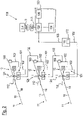
- the control system 100 includes sensor arrays 101 and display units 160, with each shelf 10 being assigned one of the sensor arrays 101 and one of the display units 160 in each case.
- the sensor arrangements 101 each comprise an occupancy sensor 110 and a loading sensor 120.
- the occupancy sensors 110, the loading sensors 120 and the display units 160 are each arranged on the storage side 12 of the associated shelf 10.
- the occupancy sensors 110 have a measuring range 112 and the loading sensors 120 have a measuring range 124 .
- the occupancy sensors 110 and the loading sensors 120 are each arranged below a compartment level 14 of the associated shelf compartment 10 .
- the occupancy sensors 110, the loading sensors 120 and the display units 160 are connected to a control unit 170 and a control unit 130 of the control system 100 via a data line 102 .
- the occupancy sensors 110, the loading sensors 120 and the display units 160 are connected in series to the data line 102 and the control unit 170 is arranged at the beginning of the data line 102.
- the control unit 170 includes a master module 172, via which the control unit 170 is connected to the data line 102.
- Occupancy sensors 110, loading sensors 120, display units 160 and control unit 170 form communication participants connected to data line 102.
- the data line 102 includes line segments that extend between adjacent communication participants.
- the control unit 170 is connected to the control unit 130 via a further data line 103, so that the communication participants of the control system 100 connected to the data line 102 are connected to the control unit 130 via the data line 102, the control unit 170 and the further data line 103.
- the control unit 130 includes a processing unit 132, which can be embodied as a logic unit, for example a microprocessor, a microcontroller, an ASIC or an FPGA.
- An identification unit 140 is connected to the control unit 130 , preferably to the processing unit 132 , via a communication line 141 .
- the identification unit 140 is designed to detect an identifier 9 attached to a storage material unit 4 to be inserted and to transmit the identifier 9 to the control unit 130, in particular to the processing unit 132.
- the identifier 9 can be in the form of an RFID tag, barcode, number sequence or the like.
- Assignment data 136 are stored in the control unit 130, which assign the read-in identifier 9 to a target shelf compartment for the storage material unit 4 to be inserted.
- length information 134 is stored in the control unit 130, which assigns a length of the storage material unit 4 to be inserted to the read-in identifier 9.
- the assignment data 136 can in particular assign a first target shelf compartment to a first identifier of first storage material units and assign a second target shelf compartment different from the first target shelf compartment to a second identifier of second storage material units that is different from the first identifier.
- the length information 134 can assign a first length to the first identifier and a second length different from the first length to the second identifier.
- Controlling the loading of the flow rack unit 1 by the control system 100 includes detecting the identifier 9 by the identification unit 140 and transmitting the identifier 9 to the control unit 130.
- the control also includes determining the target shelf using the transmitted identifier 9 and identifying the target shelf by means of the display unit 160 assigned to the target shelf compartment.
- control data for the assigned display unit 160 are transmitted via the control unit 170 and the data line 102 in order to emit a first light signal through the display unit 160 and thereby identify the target shelf compartment.
- Controlling then includes transmitting corresponding loading sensor data from loading sensor 120 to control unit 130. Controlling then includes transmitting further control data from control unit 130 to display unit 160 of the target shelf compartment in order to end the transmission of the first light signal.
- the controlling then includes a transmission of loading sensor data from the loading sensor 120 assigned to the wrong shelf compartment 10 to the control unit 130 and a transmission of control data from the control unit to the one assigned to the wrong shelf compartment 10 Display unit 160 to cause a second light signal to be emitted by the display unit 160 associated with the wrong shelf compartment 10 .
- the control comprises a transmission of corresponding load sensor data from the load sensor 120 of the target shelf compartment to the control unit 130.
- the control then comprises a transmission of control data to the display unit 160 of the target shelf compartment, to stop sending the first light signal, and transmitting control data to the display unit 160 of the wrong shelf 10 to stop sending the second light signal.
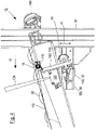
- the occupancy sensor 110 and the load sensor 120 are below the shelf level 14 of the shelf 10 on a common holder 155 of a holding device 150.
- the measuring range 112 of the occupancy sensor 110 intersects the compartment level 14 between the removal side 11 and the storage side 12.
- the occupancy sensor 110 is designed to detect a distance 5 from the rearmost storage material unit 3.
- the measuring range 112 of the occupancy sensor 110 is arranged symmetrically about a measuring axis 114 of the occupancy sensor 110 and the measuring range 124 of the loading sensor 120 is arranged symmetrically about a measurement axis 125 of the loading sensor 120 .
- the sensor arrangement 101 can also only include the occupancy sensor 110 and not the loading sensor 120 as well.
- the detection area 112 of the occupancy sensor 110 can be aligned in such a way that it intersects the compartment level 14 in front of an intersection 126, the intersection 126 at the in 3 illustrated embodiment is given by the point of intersection between the compartment level 14 and the measuring area 124 of the loading sensor 120 which is closest to the storage side 12 .
- the intersection 126 defines a start of an insertion area of the shelf compartment 10.
- the area 51 is therefore shorter than the distance between the intersection 126 and the occupancy sensor 110, so that the loading sensor 120 can be dispensed with. If necessary, the angle of incidence of the occupancy sensor 110 to the compartment level 14 could also be selected to be larger.
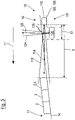
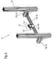
- FIG 4 shows a side view and figure 5 shows a perspective view of the storage area 12 of the shelf compartment 10 with the holding device 150 for the loading sensor 120 and the occupancy sensor 110.
- the holding device 150 is arranged on a rack framework 30 of the flow rack 1 and comprises a cross member 32, two longitudinal members 34 and the holder 155 for the occupancy sensor 110 and the loading sensor 120.
- the cross member 32 and the longitudinal members 34 are each designed as profiles which are elongated in a carrier longitudinal direction, preferably designed as groove profiles.
- the holder 155 is designed as a one-piece bent sheet metal part.
- the longitudinal beams 34 are arranged on opposite sides of the shelf compartment 10 in each case.
- the longitudinal direction of the longitudinal supports 34 is aligned parallel to the longitudinal direction 17 of the shelf compartment 10 .
- the longitudinal direction of the cross member 32 is aligned along a transverse direction 40 oriented parallel to the compartment plane 14 and perpendicular to the longitudinal direction 17 .
- the cross member 32 is connected at each of its two ends to one of the longitudinal members 34 so that it can rotate in a direction of inclination 43 and can be displaced in the longitudinal direction 17 .
- a transverse axis, about which the crossbeam 32 is rotatably arranged, runs parallel to the transverse direction 40.
- the crossbeam 32 is preferably connected at both of its ends to grooves of the longitudinal beams 34 running along the longitudinal direction 17.
- the longitudinal beams 34 are each connected to the rack frame 30 so that they can be displaced in a vertical direction 41 oriented perpendicularly to the longitudinal direction 17 and perpendicularly to the transverse direction 40 .
- the longitudinal beams 34 are preferably connected to a groove of the rack frame 30 running in the vertical direction 41 .
- the holder 155 is connected to the crossbeam 32, preferably with a groove of the crossbeam 32 running in the transverse direction 40, in a displaceable manner along the transverse direction 40. The holder 155 can thus be displaced in the vertical direction 41 and in the transverse direction 40 and is arranged on the flow rack 1 such that it can be rotated about the transverse direction 40 .
- the shelf 10 comprises transport means 20 in order to transport the storage material units 2 from the storage side 12 to the removal side 11 .
- the transport means 20 are designed as rollers arranged along the shelf compartment 10 .
- FIG. 6 shows the cross member 32 with the holder 155, the occupancy sensor 110 and the loading sensor 120.
- the holder 155 is on a running in the transverse direction 40 Groove of the cross member 32, which forms a transverse guide 33 for the holder 155 attached.
- the measuring range 112 of the occupancy sensor 110 is shown.
- the measurement area 112 is linear in a vertical direction 118 oriented perpendicularly to the compartment plane 14 .
- the measuring range 112 of the occupancy sensor 110 has a cross-sectional area 115 perpendicular to the measuring direction 114 of the occupancy sensor 110, whose height 117 oriented in the height direction 118 is greater than its width 116 oriented perpendicular to the height direction 118.
- the height 117 can, for example, be five times, preferably ten times , preferably one hundred times greater than the width 116.
- the holder 155 comprises a contact part 157, which is designed as a flat sheet metal section and on which in 7 not shown cross member 32 is present.
- a fastening element 154 for fastening the holder 155 to the cross member 32 is formed in the contact part 157 .
- the fastening element 154 is designed as a through hole in the contact part 157 for receiving a screw.
- Two transverse guide elements 153 oriented perpendicularly to the plane of the contact part 157 are formed on the contact part 157 and engage in the transverse guide 33 of the cross member 32 .
- An occupancy sensor receptacle 151 and a loading sensor receptacle 152 are also formed on the contact part 157 .
- the occupancy sensor mount 151 and the load sensor mount 152 are each designed as flat sheet metal sections.
- Occupancy sensor mount 151 is oriented perpendicular to loading sensor mount 152 .
- the occupancy sensor mount 151 and the loading sensor mount 152 are each oriented perpendicular to the contact part 157 .
- Occupancy sensor mount 151 is oriented parallel to transverse direction 40 and loading sensor mount 152 perpendicular to transverse direction 40 .
Landscapes
- Business, Economics & Management (AREA)
- Engineering & Computer Science (AREA)
- Economics (AREA)
- Mechanical Engineering (AREA)
- Physics & Mathematics (AREA)
- General Physics & Mathematics (AREA)
- Marketing (AREA)
- Development Economics (AREA)
- Finance (AREA)
- Entrepreneurship & Innovation (AREA)
- Human Resources & Organizations (AREA)
- Accounting & Taxation (AREA)
- Operations Research (AREA)
- Quality & Reliability (AREA)
- Strategic Management (AREA)
- Tourism & Hospitality (AREA)
- General Business, Economics & Management (AREA)
- Theoretical Computer Science (AREA)
- Warehouses Or Storage Devices (AREA)
Claims (9)
- Système de commande (100) destiné à une unité de rayonnage pour stockage dynamique (1) pour la mise à disposition d'unités de matériau de stockage (2) dans au moins deux casiers de rayonnage (10),
dans lequelle système de commande (100) comprend au moins deux ensembles capteurs (101) et une unité de commande (130),les ensembles capteurs (101) sont connectés à l'unité de commande (130) via une ligne de données commune (102),les ensembles capteurs (101) comprennent chacun un capteur d'occupation (110) réalisé sous forme de capteur de distance,les capteurs d'occupation (110) sont réalisés pour être associés chacun à l'un des casiers de rayonnage (10) et pour être agencés sur un côté d'insertion (12) du casier de rayonnage associé (10), de telle sorte qu'une zone de mesure (112) du capteur d'occupation respectif (110) est orientée depuis le côté d'insertion (12) du casier de rayonnage (10) en direction d'un côté de prélèvement (11) du casier de rayonnage (10) opposé au côté d'insertion (12), afin de mesurer une distance (5) par rapport à une unité de matériau de stockage (3) la plus arrière, insérée dans le casier de rayonnage associé (10), et la plus proche du capteur d'occupation (110),chaque capteur d'occupation (110) est réalisé pour transmettre à l'unité de commande (130), via la ligne de données (102), des données de distance représentant la distance mesurée (5), afin de détecter dans l'unité de commande (130) un nombre d'unités de matériau de stockage (2) insérées dans les casiers de rayonnage (10),caractérisé en ce quedans chaque ensemble capteur (101), le capteur d'occupation (110) est réalisé pour détecter une insertion d'une unité de matériau de stockage à insérer (4) sur le côté d'insertion (12) du casier de rayonnage associé (10) et pour transmettre à l'unité de commande (130), via la ligne de données (102), des données de capteur de chargement (122) indiquant l'insertion, ou dans chaque ensemble capteur (101), il est prévu en supplément un capteur de chargement (120) qui est réalisé pour détecter une insertion d'une unité de matériau de stockage à insérer (4) sur le côté d'insertion (12) du casier de rayonnage associé (10) et pour transmettre à l'unité de commande (130), via la ligne de données (102), des données de capteur de chargement (122) indiquant l'insertion, ou dans une partie des ensembles capteurs (101), le capteur d'occupation (110) est réalisé pour détecter une insertion d'une unité de matériau de stockage à insérer (4) sur le côté d'insertion (12) du casier de rayonnage associé (10) et pour transmettre à l'unité de commande (130), via la ligne de données (102), des données de capteur de chargement (122) indiquant l'insertion, et dans l'autre partie des ensembles capteurs (101), il est prévu en supplément un capteur de chargement (120) qui est réalisé pour détecter une insertion d'une unité de matériau de stockage à insérer (4) sur le côté d'insertion (12) du casier de rayonnage associé (10) et pour transmettre à l'unité de commande (130), via la ligne de données (102), des données de capteur de chargement (122) indiquant l'insertion. - Système de commande (100) selon la revendication 1,
dans lequel les ensembles capteurs (101) sont connectés en série par la ligne de données (102). - Système de commande (100) selon l'une des revendications précédentes,
dans lequel les capteurs d'occupation (110) sont réalisés pour mesurer les distances (5) au moyen du principe de parcours de la lumière. - Système de commande (100) selon l'une des revendications précédentes, dans lequel le système de commande (100) comprend des unités d'affichage (160) associables aux casiers de rayonnage individuels (10),
l'unité de commande (130) est réalisée pour transmettre des données de commande pour les unités d'affichage (160) via la ligne de données (102) afin d'identifier l'un des casiers de rayonnage (10) comme un casier de rayonnage cible pour l'unité de matériau de stockage à insérer (4). - Système de commande (100) selon l'une des revendications précédentes, dans lequel le système de commande (100) comprend une unité d'identification (140),l'unité d'identification (140) est réalisée pour détecter et transmettre à l'unité de commande (130) un identifiant (9) de l'unité de matériau de stockage à insérer (4),l'unité de commande (130) est réalisée pour déterminer, à l'aide de l'identifiant (9), un casier de rayonnage cible pour l'unité de matériau de stockage à insérer (4).
- Système de commande (100) selon l'une des revendications précédentes, dans lequelune première longueur de premières unités de matériau de stockage (2) est mémorisée dans l'unité de commande (130),une deuxième longueur de deuxièmes unités de matériau de stockage (2) est mémorisée dans l'unité de commande (130),l'unité de commande (130) est réalisée pour tenir compte, lors de la détermination des distances (5), de la première longueur ou de la deuxième longueur en fonction d'un signal d'identification amené à l'unité de commande (130) pour identifier l'unité de matériau de stockage à insérer (4).
- Système de commande (100) selon l'une des revendications précédentes, dans lequel le système de commande (100) comprend une unité de contrôle (170),l'unité de contrôle (170) est connectée à des ensembles capteurs (102) via la ligne de données (102),l'unité de contrôle (170) est connectée à l'unité de commande (130) par une autre ligne de données (103),l'unité de contrôle (170) comprend un module maître (172) pour commander une transmission de données sur la ligne de données (102),les ensembles capteurs (101) sont connectés à la ligne de données (102) en tant qu'unités esclaves pilotées par le module maître (172).
- Unité de rayonnage pour stockage dynamique (1) destinée à la mise à disposition d'unités de matériau de stockage (2), comprenant au moins deux casiers de rayonnage (10) et un système de commande (100) selon l'une des revendications précédentes,
dans laquelleles casiers de rayonnage (10) présentent chacun un côté de prélèvement (11) et un côté d'insertion (12) opposé au côté de prélèvement (11),les casiers de rayonnage (10) sont réalisés pour mettre à disposition, dans un plan de casier (14), les unités de matériau de stockage (2) respectives, agencées les unes après les autres à partir du côté de prélèvement (11) en direction du côté d'insertion (12),un ensemble capteur (101) du système de commande (100) est associé à chaque casier de rayonnage (10),les ensembles capteurs (101) sont disposés chacun sur le côté d'insertion (12) du casier de rayonnage (10) associé,les zones de mesure (112) des capteurs d'occupation (110) sont orientées chacune depuis le côté d'insertion (12) du casier de rayonnage associé (10) en direction du côté de prélèvement (11) du casier de rayonnage associé (10). - Utilisation d'au moins deux capteurs de distance comme capteurs d'occupation (110) d'un système de commande (100) destiné à unité de rayonnage pour stockage dynamique (1) mettant à disposition des unités de matériau de stockage (2) dans au moins deux casiers de rayonnage (10),
dans laquelleles capteurs de distance sont associés chacun à l'un des casiers de rayonnage (10) et sont disposés sur un côté d'insertion (12) du casier de rayonnage associé (10), de telle sorte que des zones de mesure (112) des capteurs de distance sont orientées depuis le côté d'insertion (12) du casier de rayonnage associé (10) en direction d'un côté de prélèvement (11) du casier de rayonnage associé (10) opposé au côté d'insertion (12),une distance respective (5) par rapport à une unité de matériau de stockage (3) la plus arrière, insérée dans le casier de rayonnage (10) associé au capteur de distance respectif, et la plus proche du capteur de distance respectif, est mesurée à l'aide des capteurs de distance,les capteurs de distance sont connectés à une unité de commande (130) du système de commande (100) via une ligne de données (102) commune, des données de distance représentant les distances mesurées (5) sont transmises des capteurs de distance à l'unité de commande (130) via la ligne de données (102), afin de détecter dans l'unité de commande (130) un nombre d'unités de matériau de stockage (2) agencées dans les casiers de rayonnage (10),des données de capteurs de chargement sont transmises à l'unité de commande (130) via la ligne de données (102), afin de commander une insertion des unités de matériau de stockage (2) dans les casiers de rayonnage (10),caractérisée en ce queles capteurs d'occupation (110) formés par les capteurs de distance sont réalisés pour détecter l'insertion des unités de matériau de stockage (2) dans des zones d'insertion des casiers de rayonnage (10) disposées sur le côté d'insertion (12), et pour générer et transmettre à l'unité de commande (120) des données de capteur de chargement (122) indiquant l'insertion des unités de matériau de stockage (2).
Priority Applications (2)
| Application Number | Priority Date | Filing Date | Title |
|---|---|---|---|
| EP18207947.5A EP3657123B1 (fr) | 2018-11-23 | 2018-11-23 | Etagère inclinée et système de controle pour une etagère inclinée |
| US16/691,009 US11660740B2 (en) | 2018-11-23 | 2019-11-21 | Flow rack unit and control system for a flow rack unit |
Applications Claiming Priority (1)
| Application Number | Priority Date | Filing Date | Title |
|---|---|---|---|
| EP18207947.5A EP3657123B1 (fr) | 2018-11-23 | 2018-11-23 | Etagère inclinée et système de controle pour une etagère inclinée |
Publications (2)
| Publication Number | Publication Date |
|---|---|
| EP3657123A1 EP3657123A1 (fr) | 2020-05-27 |
| EP3657123B1 true EP3657123B1 (fr) | 2022-06-29 |
Family
ID=64456794
Family Applications (1)
| Application Number | Title | Priority Date | Filing Date |
|---|---|---|---|
| EP18207947.5A Active EP3657123B1 (fr) | 2018-11-23 | 2018-11-23 | Etagère inclinée et système de controle pour une etagère inclinée |
Country Status (2)
| Country | Link |
|---|---|
| US (1) | US11660740B2 (fr) |
| EP (1) | EP3657123B1 (fr) |
Families Citing this family (4)
| Publication number | Priority date | Publication date | Assignee | Title |
|---|---|---|---|---|
| DE102020115816A1 (de) * | 2020-06-16 | 2021-12-16 | Liebherr-Verzahntechnik Gmbh | Speicher- und/oder Fertigungssystem mit wenigstens einem Handhabungsgerät |
| FI129206B (en) | 2020-11-23 | 2021-09-15 | Ferrometal Oy | Device, ordering system and procedure for monitoring stock level |
| EP4326119A1 (fr) * | 2021-04-23 | 2024-02-28 | Captana GmbH | Appareil de présentation de produit doté d'une structure de rayonnage pour le dépôt d'articles, et doté d'un capteur pour la détection du stock |
| DE102022122268A1 (de) | 2021-09-03 | 2023-03-09 | Ifm Electronic Gmbh | Computerimplementiertes Verfahren zur Steuerung des Vorrats an Lagermaterialeinheiten an Fertigungs-Arbeitsplätzen einer Produktionsanlage |
Family Cites Families (10)
| Publication number | Priority date | Publication date | Assignee | Title |
|---|---|---|---|---|
| DE102008037658A1 (de) * | 2008-08-14 | 2010-02-25 | Knapp Logistik Automation Gmbh | Verfahren und Vorrichtung zum Kommissionieren von Stückgut mit einem Kommissionierautomaten und beigeordnetem Durchlaufregal |
| US8386074B2 (en) * | 2010-05-25 | 2013-02-26 | Interactive Vending Corporation | Vending machine |
| DE102010044614B4 (de) * | 2010-09-02 | 2013-08-01 | SSI Schäfer Noell GmbH Lager- und Systemtechnik | Arbeitsplatz und Verfahren zum manuellen, beleglosen stationären Kommissionieren von Stückgütern sowie Lager- und Kommissionieranlage |
| US20160048798A1 (en) * | 2013-01-11 | 2016-02-18 | Tagnetics, Inc. | Inventory sensor |
| DE102015120000A1 (de) * | 2015-11-18 | 2017-05-18 | Würth Elektronik Ics Gmbh & Co. Kg | Sensorbaugruppe, Sensorsystem und Lagervorrichtung |
| BE1023861B1 (nl) * | 2016-02-19 | 2017-08-23 | FACIL CORPORATE, besloten vennootschap met beperkte aansprakelijkheid | Inrichting voor het bevoorraden van rekken en werkwijze daarbij toegepast |
| DE102016108582B3 (de) | 2016-05-10 | 2017-07-13 | Werma Holding Gmbh + Co. Kg | Durchlauf-Regaleinheit zur Bereitstellung von Material in Logistik- und Fertigungsprozessen |
| US20180165711A1 (en) * | 2016-12-13 | 2018-06-14 | Frito-Lay North America, Inc. | Smart Product Display Systems and Related Methods Providing Consumer Behavior Analytics |
| US20180225625A1 (en) * | 2017-02-06 | 2018-08-09 | Cornelius, Inc. | Inventory Management System and Method |
| US10831431B2 (en) * | 2017-04-18 | 2020-11-10 | Anthony, Inc. | Shelving display |
-
2018
- 2018-11-23 EP EP18207947.5A patent/EP3657123B1/fr active Active
-
2019
- 2019-11-21 US US16/691,009 patent/US11660740B2/en active Active
Also Published As
| Publication number | Publication date |
|---|---|
| EP3657123A1 (fr) | 2020-05-27 |
| US20200164500A1 (en) | 2020-05-28 |
| US11660740B2 (en) | 2023-05-30 |
Similar Documents
| Publication | Publication Date | Title |
|---|---|---|
| EP3657123B1 (fr) | Etagère inclinée et système de controle pour une etagère inclinée | |
| EP2903086B1 (fr) | Dispositif de lecture RFID pour la détection de l'occupation d'étagères | |
| EP2668118B1 (fr) | Dispositif et procédé pour effectuer l'inventaire d'un entrepot, et utilisation d'un produit-programme-ordinateur dans un tel entrepot | |
| EP1664836B1 (fr) | Systeme de positionnement assiste par transpondeur | |
| EP3464124B1 (fr) | Transfert à contrôle de contours | |
| EP2700596B1 (fr) | Système de préparation de commandes | |
| EP3291144B1 (fr) | Dispositif rfid et procede de reconnaissance d'occupation de casier | |
| EP1867587A1 (fr) | Dispositif et procédé de préparation de biens empilables | |
| DE3711237A1 (de) | Verfahren und vorrichtung zur steuerung von stueckgutfoerderanlagen mit hilfe von transpondern | |
| DE102020100407A1 (de) | Werkzeugmaschine, Verwaltungssystem und Werkzeugverschlechterungsfeststellungsverfahren | |
| DE102006056556A1 (de) | Volumenbestimmung für auf einem Schalenförderer bewegte Objekte | |
| DE102012016552A1 (de) | Kommissioniersystem | |
| EP3832343A1 (fr) | Module de détection pour dispositif palier pourvu de dispositifs capteurs permettant de détecter une erreur ou un niveau de remplissage de marchandises entreposées au moyen de la mesure de distance optique | |
| EP1910193B1 (fr) | Dispositif pour realiser une detection sans fil du niveau de remplissage d'une installation de preparation de commande | |
| EP2607867B1 (fr) | Installation de stockage et procédé de surveillance des stocks pour une installation de stockage | |
| DE102020001213A1 (de) | Positionsberechnungssystem, Positionsberechnungsverfahren und automatisch geführtes Fahrzeug | |
| EP3273382B1 (fr) | Dispositif de lecture rfid et procédé de reconnaissance d'occupation de casier sur une étagère | |
| EP1910194A1 (fr) | Systeme de stockage a rayonnages comprenant une station d'entree | |
| EP3171125B1 (fr) | Procede de reconnaissance d'un profil d'un systeme passant dans une zone de detection d'un capteur de distance | |
| DE102017126591B3 (de) | System zur Fachbelegungsüberwachung | |
| DE202016103887U1 (de) | RFID-Lesevorrichtung zur Fachbelegungserkennung in einem Regal | |
| EP3323517B1 (fr) | Système de tri et procédé de suivi d'un tri d'un produit à trier dans un registre de tri | |
| EP2830977B1 (fr) | Système de courroie centrale d'une installation de préparation de commandes | |
| DE202006018606U1 (de) | Volumenbestimmung für auf einem Schalenförderer bewegte Objekte | |
| EP2479720B1 (fr) | Système et procédé de stockage et de surveillance de marchandises à l'aide de la technologie RFID |
Legal Events
| Date | Code | Title | Description |
|---|---|---|---|
| PUAI | Public reference made under article 153(3) epc to a published international application that has entered the european phase |
Free format text: ORIGINAL CODE: 0009012 |
|
| STAA | Information on the status of an ep patent application or granted ep patent |
Free format text: STATUS: REQUEST FOR EXAMINATION WAS MADE |
|
| 17P | Request for examination filed |
Effective date: 20190513 |
|
| AK | Designated contracting states |
Kind code of ref document: A1 Designated state(s): AL AT BE BG CH CY CZ DE DK EE ES FI FR GB GR HR HU IE IS IT LI LT LU LV MC MK MT NL NO PL PT RO RS SE SI SK SM TR |
|
| AX | Request for extension of the european patent |
Extension state: BA ME |
|
| STAA | Information on the status of an ep patent application or granted ep patent |
Free format text: STATUS: EXAMINATION IS IN PROGRESS |
|
| 17Q | First examination report despatched |
Effective date: 20210319 |
|
| STAA | Information on the status of an ep patent application or granted ep patent |
Free format text: STATUS: EXAMINATION IS IN PROGRESS |
|
| GRAP | Despatch of communication of intention to grant a patent |
Free format text: ORIGINAL CODE: EPIDOSNIGR1 |
|
| STAA | Information on the status of an ep patent application or granted ep patent |
Free format text: STATUS: GRANT OF PATENT IS INTENDED |
|
| INTG | Intention to grant announced |
Effective date: 20220322 |
|
| GRAS | Grant fee paid |
Free format text: ORIGINAL CODE: EPIDOSNIGR3 |
|
| GRAA | (expected) grant |
Free format text: ORIGINAL CODE: 0009210 |
|
| STAA | Information on the status of an ep patent application or granted ep patent |
Free format text: STATUS: THE PATENT HAS BEEN GRANTED |
|
| AK | Designated contracting states |
Kind code of ref document: B1 Designated state(s): AL AT BE BG CH CY CZ DE DK EE ES FI FR GB GR HR HU IE IS IT LI LT LU LV MC MK MT NL NO PL PT RO RS SE SI SK SM TR |
|
| REG | Reference to a national code |
Ref country code: CH Ref legal event code: EP |
|
| REG | Reference to a national code |
Ref country code: DE Ref legal event code: R096 Ref document number: 502018010035 Country of ref document: DE |
|
| REG | Reference to a national code |
Ref country code: AT Ref legal event code: REF Ref document number: 1501621 Country of ref document: AT Kind code of ref document: T Effective date: 20220715 |
|
| REG | Reference to a national code |
Ref country code: IE Ref legal event code: FG4D Free format text: LANGUAGE OF EP DOCUMENT: GERMAN |
|
| REG | Reference to a national code |
Ref country code: LT Ref legal event code: MG9D |
|
| PG25 | Lapsed in a contracting state [announced via postgrant information from national office to epo] |
Ref country code: SE Free format text: LAPSE BECAUSE OF FAILURE TO SUBMIT A TRANSLATION OF THE DESCRIPTION OR TO PAY THE FEE WITHIN THE PRESCRIBED TIME-LIMIT Effective date: 20220629 Ref country code: NO Free format text: LAPSE BECAUSE OF FAILURE TO SUBMIT A TRANSLATION OF THE DESCRIPTION OR TO PAY THE FEE WITHIN THE PRESCRIBED TIME-LIMIT Effective date: 20220929 Ref country code: LT Free format text: LAPSE BECAUSE OF FAILURE TO SUBMIT A TRANSLATION OF THE DESCRIPTION OR TO PAY THE FEE WITHIN THE PRESCRIBED TIME-LIMIT Effective date: 20220629 Ref country code: HR Free format text: LAPSE BECAUSE OF FAILURE TO SUBMIT A TRANSLATION OF THE DESCRIPTION OR TO PAY THE FEE WITHIN THE PRESCRIBED TIME-LIMIT Effective date: 20220629 Ref country code: GR Free format text: LAPSE BECAUSE OF FAILURE TO SUBMIT A TRANSLATION OF THE DESCRIPTION OR TO PAY THE FEE WITHIN THE PRESCRIBED TIME-LIMIT Effective date: 20220930 Ref country code: FI Free format text: LAPSE BECAUSE OF FAILURE TO SUBMIT A TRANSLATION OF THE DESCRIPTION OR TO PAY THE FEE WITHIN THE PRESCRIBED TIME-LIMIT Effective date: 20220629 Ref country code: BG Free format text: LAPSE BECAUSE OF FAILURE TO SUBMIT A TRANSLATION OF THE DESCRIPTION OR TO PAY THE FEE WITHIN THE PRESCRIBED TIME-LIMIT Effective date: 20220929 |
|
| REG | Reference to a national code |
Ref country code: NL Ref legal event code: MP Effective date: 20220629 |
|
| PG25 | Lapsed in a contracting state [announced via postgrant information from national office to epo] |
Ref country code: RS Free format text: LAPSE BECAUSE OF FAILURE TO SUBMIT A TRANSLATION OF THE DESCRIPTION OR TO PAY THE FEE WITHIN THE PRESCRIBED TIME-LIMIT Effective date: 20220629 Ref country code: LV Free format text: LAPSE BECAUSE OF FAILURE TO SUBMIT A TRANSLATION OF THE DESCRIPTION OR TO PAY THE FEE WITHIN THE PRESCRIBED TIME-LIMIT Effective date: 20220629 |
|
| PG25 | Lapsed in a contracting state [announced via postgrant information from national office to epo] |
Ref country code: NL Free format text: LAPSE BECAUSE OF FAILURE TO SUBMIT A TRANSLATION OF THE DESCRIPTION OR TO PAY THE FEE WITHIN THE PRESCRIBED TIME-LIMIT Effective date: 20220629 |
|
| PG25 | Lapsed in a contracting state [announced via postgrant information from national office to epo] |
Ref country code: SM Free format text: LAPSE BECAUSE OF FAILURE TO SUBMIT A TRANSLATION OF THE DESCRIPTION OR TO PAY THE FEE WITHIN THE PRESCRIBED TIME-LIMIT Effective date: 20220629 Ref country code: SK Free format text: LAPSE BECAUSE OF FAILURE TO SUBMIT A TRANSLATION OF THE DESCRIPTION OR TO PAY THE FEE WITHIN THE PRESCRIBED TIME-LIMIT Effective date: 20220629 Ref country code: RO Free format text: LAPSE BECAUSE OF FAILURE TO SUBMIT A TRANSLATION OF THE DESCRIPTION OR TO PAY THE FEE WITHIN THE PRESCRIBED TIME-LIMIT Effective date: 20220629 Ref country code: PT Free format text: LAPSE BECAUSE OF FAILURE TO SUBMIT A TRANSLATION OF THE DESCRIPTION OR TO PAY THE FEE WITHIN THE PRESCRIBED TIME-LIMIT Effective date: 20221031 Ref country code: ES Free format text: LAPSE BECAUSE OF FAILURE TO SUBMIT A TRANSLATION OF THE DESCRIPTION OR TO PAY THE FEE WITHIN THE PRESCRIBED TIME-LIMIT Effective date: 20220629 Ref country code: EE Free format text: LAPSE BECAUSE OF FAILURE TO SUBMIT A TRANSLATION OF THE DESCRIPTION OR TO PAY THE FEE WITHIN THE PRESCRIBED TIME-LIMIT Effective date: 20220629 |
|
| PG25 | Lapsed in a contracting state [announced via postgrant information from national office to epo] |
Ref country code: PL Free format text: LAPSE BECAUSE OF FAILURE TO SUBMIT A TRANSLATION OF THE DESCRIPTION OR TO PAY THE FEE WITHIN THE PRESCRIBED TIME-LIMIT Effective date: 20220629 Ref country code: IS Free format text: LAPSE BECAUSE OF FAILURE TO SUBMIT A TRANSLATION OF THE DESCRIPTION OR TO PAY THE FEE WITHIN THE PRESCRIBED TIME-LIMIT Effective date: 20221029 |
|
| REG | Reference to a national code |
Ref country code: DE Ref legal event code: R097 Ref document number: 502018010035 Country of ref document: DE |
|
| PG25 | Lapsed in a contracting state [announced via postgrant information from national office to epo] |
Ref country code: AL Free format text: LAPSE BECAUSE OF FAILURE TO SUBMIT A TRANSLATION OF THE DESCRIPTION OR TO PAY THE FEE WITHIN THE PRESCRIBED TIME-LIMIT Effective date: 20220629 |
|
| PG25 | Lapsed in a contracting state [announced via postgrant information from national office to epo] |
Ref country code: DK Free format text: LAPSE BECAUSE OF FAILURE TO SUBMIT A TRANSLATION OF THE DESCRIPTION OR TO PAY THE FEE WITHIN THE PRESCRIBED TIME-LIMIT Effective date: 20220629 Ref country code: CZ Free format text: LAPSE BECAUSE OF FAILURE TO SUBMIT A TRANSLATION OF THE DESCRIPTION OR TO PAY THE FEE WITHIN THE PRESCRIBED TIME-LIMIT Effective date: 20220629 |
|
| PLBE | No opposition filed within time limit |
Free format text: ORIGINAL CODE: 0009261 |
|
| STAA | Information on the status of an ep patent application or granted ep patent |
Free format text: STATUS: NO OPPOSITION FILED WITHIN TIME LIMIT |
|
| 26N | No opposition filed |
Effective date: 20230330 |
|
| PG25 | Lapsed in a contracting state [announced via postgrant information from national office to epo] |
Ref country code: MC Free format text: LAPSE BECAUSE OF FAILURE TO SUBMIT A TRANSLATION OF THE DESCRIPTION OR TO PAY THE FEE WITHIN THE PRESCRIBED TIME-LIMIT Effective date: 20220629 |
|
| REG | Reference to a national code |
Ref country code: CH Ref legal event code: PL |
|
| GBPC | Gb: european patent ceased through non-payment of renewal fee |
Effective date: 20221123 |
|
| REG | Reference to a national code |
Ref country code: BE Ref legal event code: MM Effective date: 20221130 |
|
| PG25 | Lapsed in a contracting state [announced via postgrant information from national office to epo] |
Ref country code: LI Free format text: LAPSE BECAUSE OF NON-PAYMENT OF DUE FEES Effective date: 20221130 Ref country code: CH Free format text: LAPSE BECAUSE OF NON-PAYMENT OF DUE FEES Effective date: 20221130 |
|
| PG25 | Lapsed in a contracting state [announced via postgrant information from national office to epo] |
Ref country code: SI Free format text: LAPSE BECAUSE OF FAILURE TO SUBMIT A TRANSLATION OF THE DESCRIPTION OR TO PAY THE FEE WITHIN THE PRESCRIBED TIME-LIMIT Effective date: 20220629 Ref country code: LU Free format text: LAPSE BECAUSE OF NON-PAYMENT OF DUE FEES Effective date: 20221123 |
|
| PG25 | Lapsed in a contracting state [announced via postgrant information from national office to epo] |
Ref country code: IE Free format text: LAPSE BECAUSE OF NON-PAYMENT OF DUE FEES Effective date: 20221123 Ref country code: GB Free format text: LAPSE BECAUSE OF NON-PAYMENT OF DUE FEES Effective date: 20221123 |
|
| PG25 | Lapsed in a contracting state [announced via postgrant information from national office to epo] |
Ref country code: FR Free format text: LAPSE BECAUSE OF NON-PAYMENT OF DUE FEES Effective date: 20221130 Ref country code: BE Free format text: LAPSE BECAUSE OF NON-PAYMENT OF DUE FEES Effective date: 20221130 |
|
| PG25 | Lapsed in a contracting state [announced via postgrant information from national office to epo] |
Ref country code: IT Free format text: LAPSE BECAUSE OF FAILURE TO SUBMIT A TRANSLATION OF THE DESCRIPTION OR TO PAY THE FEE WITHIN THE PRESCRIBED TIME-LIMIT Effective date: 20220629 |
|
| PGFP | Annual fee paid to national office [announced via postgrant information from national office to epo] |
Ref country code: DE Payment date: 20231120 Year of fee payment: 6 |
|
| PG25 | Lapsed in a contracting state [announced via postgrant information from national office to epo] |
Ref country code: HU Free format text: LAPSE BECAUSE OF FAILURE TO SUBMIT A TRANSLATION OF THE DESCRIPTION OR TO PAY THE FEE WITHIN THE PRESCRIBED TIME-LIMIT; INVALID AB INITIO Effective date: 20181123 |
|
| PG25 | Lapsed in a contracting state [announced via postgrant information from national office to epo] |
Ref country code: CY Free format text: LAPSE BECAUSE OF FAILURE TO SUBMIT A TRANSLATION OF THE DESCRIPTION OR TO PAY THE FEE WITHIN THE PRESCRIBED TIME-LIMIT Effective date: 20220629 |