EP3656908A1 - Dispositif de filtrage pour machine à laver et lave-linge - Google Patents
Dispositif de filtrage pour machine à laver et lave-linge Download PDFInfo
- Publication number
- EP3656908A1 EP3656908A1 EP19211506.1A EP19211506A EP3656908A1 EP 3656908 A1 EP3656908 A1 EP 3656908A1 EP 19211506 A EP19211506 A EP 19211506A EP 3656908 A1 EP3656908 A1 EP 3656908A1
- Authority
- EP
- European Patent Office
- Prior art keywords
- filter device
- washing machine
- housing
- water
- filter
- Prior art date
- Legal status (The legal status is an assumption and is not a legal conclusion. Google has not performed a legal analysis and makes no representation as to the accuracy of the status listed.)
- Granted
Links
- 238000005406 washing Methods 0.000 title claims abstract description 96
- XLYOFNOQVPJJNP-UHFFFAOYSA-N water Substances O XLYOFNOQVPJJNP-UHFFFAOYSA-N 0.000 claims abstract description 91
- 238000001914 filtration Methods 0.000 claims abstract description 11
- 238000011109 contamination Methods 0.000 claims description 22
- 238000007789 sealing Methods 0.000 claims description 11
- 239000002184 metal Substances 0.000 claims description 7
- 238000001514 detection method Methods 0.000 claims description 5
- 230000000295 complement effect Effects 0.000 claims description 4
- 239000011859 microparticle Substances 0.000 claims description 3
- 230000003287 optical effect Effects 0.000 description 39
- 238000004140 cleaning Methods 0.000 description 10
- 238000001035 drying Methods 0.000 description 6
- 239000000835 fiber Substances 0.000 description 6
- 238000012423 maintenance Methods 0.000 description 6
- 239000000428 dust Substances 0.000 description 4
- 238000011144 upstream manufacturing Methods 0.000 description 4
- 239000002904 solvent Substances 0.000 description 3
- 230000001960 triggered effect Effects 0.000 description 3
- 238000005259 measurement Methods 0.000 description 2
- 238000000034 method Methods 0.000 description 2
- 230000000694 effects Effects 0.000 description 1
- 239000004744 fabric Substances 0.000 description 1
- 210000003127 knee Anatomy 0.000 description 1
- 230000013011 mating Effects 0.000 description 1
- 238000012544 monitoring process Methods 0.000 description 1
- 239000002245 particle Substances 0.000 description 1
- 230000035699 permeability Effects 0.000 description 1
- 239000010865 sewage Substances 0.000 description 1
- 239000007787 solid Substances 0.000 description 1
- 239000004753 textile Substances 0.000 description 1
- 239000002351 wastewater Substances 0.000 description 1
Images


Classifications
-
- D—TEXTILES; PAPER
- D06—TREATMENT OF TEXTILES OR THE LIKE; LAUNDERING; FLEXIBLE MATERIALS NOT OTHERWISE PROVIDED FOR
- D06F—LAUNDERING, DRYING, IRONING, PRESSING OR FOLDING TEXTILE ARTICLES
- D06F39/00—Details of washing machines not specific to a single type of machines covered by groups D06F9/00 - D06F27/00
- D06F39/10—Filtering arrangements
-
- D—TEXTILES; PAPER
- D06—TREATMENT OF TEXTILES OR THE LIKE; LAUNDERING; FLEXIBLE MATERIALS NOT OTHERWISE PROVIDED FOR
- D06F—LAUNDERING, DRYING, IRONING, PRESSING OR FOLDING TEXTILE ARTICLES
- D06F33/00—Control of operations performed in washing machines or washer-dryers
- D06F33/30—Control of washing machines characterised by the purpose or target of the control
- D06F33/47—Responding to irregular working conditions, e.g. malfunctioning of pumps
-
- D—TEXTILES; PAPER
- D06—TREATMENT OF TEXTILES OR THE LIKE; LAUNDERING; FLEXIBLE MATERIALS NOT OTHERWISE PROVIDED FOR
- D06F—LAUNDERING, DRYING, IRONING, PRESSING OR FOLDING TEXTILE ARTICLES
- D06F2103/00—Parameters monitored or detected for the control of domestic laundry washing machines, washer-dryers or laundry dryers
- D06F2103/42—Parameters monitored or detected for the control of domestic laundry washing machines, washer-dryers or laundry dryers related to filters or pumps
-
- D—TEXTILES; PAPER
- D06—TREATMENT OF TEXTILES OR THE LIKE; LAUNDERING; FLEXIBLE MATERIALS NOT OTHERWISE PROVIDED FOR
- D06F—LAUNDERING, DRYING, IRONING, PRESSING OR FOLDING TEXTILE ARTICLES
- D06F2105/00—Systems or parameters controlled or affected by the control systems of washing machines, washer-dryers or laundry dryers
- D06F2105/62—Stopping or disabling machine operation
-
- D—TEXTILES; PAPER
- D06—TREATMENT OF TEXTILES OR THE LIKE; LAUNDERING; FLEXIBLE MATERIALS NOT OTHERWISE PROVIDED FOR
- D06F—LAUNDERING, DRYING, IRONING, PRESSING OR FOLDING TEXTILE ARTICLES
- D06F39/00—Details of washing machines not specific to a single type of machines covered by groups D06F9/00 - D06F27/00
- D06F39/12—Casings; Tubs
- D06F39/14—Doors or covers; Securing means therefor
Definitions
- the present invention relates to a filter device for a washing machine for filtering water and a washing machine with such a filter device.
- most of the washing machines known to date provide a filter device which is arranged in a lower part of the washing machine, in particular near the bottom of the washing machine.
- the filter device is hidden behind a flap and inserted horizontally into the housing of the washing machine.
- the flap In order to clean the one sieve of the filter device, the flap usually has to be opened by a user on his knees, the sieve mostly loosened by screwing and then removed. This causes puddles to form in front of the machine due to the leakage of residual water.
- a drip tray for water must be provided will.
- the flap can then be opened to access the filter.
- the next step is to drain water from the filter.
- an outlet is attached next to the filter, through which water that is in the water circuit of the washing machine, in particular in the filter, can run off and be collected in the drip tray.
- the outlet can be provided with a cloth or a stopper. Only then can the filter be removed for cleaning.
- Such a washing machine with filter devices is for example from the document EP 1 751 343 A1 known.
- dryer-washing machine combinations which likewise have a filter device.
- This filter device must be suitable both for filtering water in a washing cycle and for filtering hot air in a drying cycle.
- the publication shows EP 2 053 157 A1 a dryer-washer combination.
- the dryer-washing machine combination has a washing assembly, a dryer assembly and a filter assembly.
- the wash assembly is configured to circulate a solvent along a predetermined wash path that extends through a laundry drum.
- the dryer assembly is configured to circulate hot air along a predetermined drying path that extends through the drum.
- the filter assembly is configured to remove fibers, lint and dust from the solvent circulating along the wash path during a wash cycle.
- the filter assembly is further configured to remove fibers, lint and dust from the hot air circulating along the drying path during the drying cycle.
- the filter assembly is formed such that the fibers, lint, and dust from the solvent are collected at a predetermined position along the drying path so that hot air flows over the collected fibers, lint, and dust during the drying cycle.
- a filter device for a washing machine having a housing and a filter device for filtering water, the housing having a water inlet and a water outlet, the filter device for filtering the water in the housing at least is partially arranged between the water inlet and the water outlet, the housing being watertight at least between the water inlet and the water outlet.
- the water flows through the water inlet into the interior of the housing of the filter device and out of the interior through the water outlet. Since the filter device is arranged between the water inlet and the water outlet, the water flows through the filter device and is thereby filtered.
- the upstream and downstream directions are defined according to the flow direction of the water.
- the proposed filter device for a washing machine thus has a compact and watertight structure.
- the filter device further comprises a sieve element, the sieve element for filtering the water being arranged between the water inlet and the water outlet, in particular the sieve element being designed as a sieve basket.
- the sieve element is arranged in such a way that the water flows through the sieve element when the water flows from the water inlet to the water outlet.
- the water is filtered.
- the filter device has an insert element, the insert element being insertable into the sieve element, in particular wherein the insert element has a filter labyrinth for guiding the water flow from the water inlet to the water outlet.
- the filter labyrinth forms, for example, a large number of webs on which the water is diverted.
- foreign bodies such as hair, lint or metal parts, can collect not only in the sieve element but also in the insert element. This improves the overall filter efficiency of the filter device.
- larger foreign bodies can be stopped in the insert element, which could possibly damage the sieve element or block the waste water pump if it continues to flow, which would result in a customer service operation.
- the housing also has an opening through which the filter device can be inserted into the housing.
- the filter device can be removed for cleaning in a simple manner and can be reinserted into the housing after cleaning.
- the filter device also has a closing element with which the opening of the housing can be closed.
- the housing of the filter device can be closed in a simple manner by means of the closing element. This makes it possible, in particular, to close the housing completely watertight during operation of the washing machine, in particular with the addition of a sealing element which effects a seal between the housing and the closing element.
- a non-positive connection to the housing is preferably achieved by the closing element.
- the closing element has a thread and the housing in the opening has a mating thread that is complementary thereto, the thread rotating in particular in a direction of rotation about an axis of rotation.
- the closing element can thus be screwed into the opening of the housing in order to close the opening of the housing.
- the closing element is fixed, in particular free of play, to the housing.
- this configuration offers a good possibility of sealing if a sealing element is used between the housing and the closing element.
- a sealing element is arranged between the closing element and the housing, in particular a sealing ring.
- This configuration enables a good seal of the water-bearing housing from the environment.
- a non-positive connection of the closing element to the housing is preferably produced, so that the sealing element is pressed against the housing. This improves the seal.
- the sieve element, the insert element and the closing element can be connected to one another perpendicular to the direction of rotation, wherein in particular the sieve element, the insert element and the closing element can be coupled to one another in a rotationally fixed manner.
- the filter device This enables the filter device to be inserted as a whole into the housing or removed from the housing.
- the individual elements of the filter device can be easily disassembled for cleaning or maintenance of the elements.
- the filter device also has a sensor device which is designed to detect foreign bodies, in particular fluff, lint, microparticles and / or metal.
- a degree of contamination of the filter device By means of the sensor device it is possible to determine a degree of contamination of the filter device. On the basis of this sensor data, a decision can then be made, for example, as to whether the filter device needs to be cleaned or whether the detected foreign bodies could damage the filter or other components located downstream, such as a sewage pump. In some configurations, a warning can be triggered, in particular visually or acoustically, when a first threshold value of the contamination is exceeded and / or a switch-off signal is generated when a second threshold value of the contamination is exceeded.
- the sensor device has an optical and / or a magnetic sensor.
- contamination or a fill level of the filter device can be determined in a simple manner.
- a magnetic foreign body can be easily identified with a magnetic sensor.
- a warning can be triggered, in particular visually or acoustically, when a first threshold value with regard to the size and / or amount of the metallic foreign bodies is exceeded and / or a switch-off signal is generated when a second threshold value with respect to the size and / or The amount of metallic foreign bodies is exceeded.
- the optical sensor has an optical transmitter and an optical receiver, which are arranged on opposite sides of the filter device, the optical transmitter sending light pulses to the optical receiver.
- a light pulse can be blocked by foreign bodies or reaches the receiver with reduced intensity due to the presence of foreign bodies in the filter device.
- a warning can be triggered, in particular visually or acoustically, when a first threshold value of the determined intensity at the receiver is undershot and / or a switch-off signal is generated when a second threshold value of the determined intensity at the receiver is undershot.
- the screen element has two recesses on two opposite sides, which are arranged such that in the inserted state a beam path of the light pulses runs through the recesses.
- the recesses are designed with a round cross section, in particular as bores.
- the magnetic sensor is arranged upstream of the sieve element.
- This arrangement of the magnetic sensor makes it possible to recognize a metallic object or foreign body before reaching the sieve element. This makes it possible to take appropriate measures to prevent damage to the screen element. For example, the operation of the washing machine can be stopped when a metallic foreign body is detected.
- the sensor device generates an analog or digital sensor signal based on the detection of foreign bodies in the filter device.
- the sensor signal can correspond, for example, to a measured value, in particular an inductance in the case of a magnetic sensor or an intensity of a light pulse in the case of an optical sensor.
- This measured value can be passed on analog or digital.
- the sensor device can also be set up to determine a degree of contamination or a type of foreign body, in particular a size of the solid body, on the basis of the measured data, the sensor signal containing the results of this determination.
- the washing machine has a washing machine housing, a drum arranged in the washing machine housing, and a door, the washing machine housing having access to the drum, the door being arranged at the access to the washing machine housing, the filter device is located at the entrance.
- the filter device is preferably arranged on a lower side of the access and the opening of the housing of the filter device is arranged on an upper side of the housing. This avoids that when the filter device is removed from the housing for maintenance or cleaning or when the filter device is reinserted into the housing after the maintenance or cleaning, no water has to be collected.
- the washing machine furthermore has a control device which is set up to control the washing machine taking into account the sensor signal.
- the sensor signal contains information about foreign bodies in the filter device or about a degree of contamination of the filter device.
- the control device can therefore take appropriate measures taking this information into account.
- a user can be provided with an optical or acoustic signal that includes the detection of a foreign body in the filter device, the degree of contamination of the filter device, or an instruction for maintenance or cleaning of the filter device.
- the control device taking into account the information received, operates the Controls the washing machine accordingly. For example, a pump output of a pump in the water cycle of the washing machine can be reduced.
- control device determines a degree of contamination of the filter device on the basis of the sensor signal, in particular a fill level of the sieve element being determined.
- the control device can use this measurement data to determine the degree of contamination.
- control device determines on the basis of the sensor signal whether the sensor signal exceeds a first threshold value, in particular as a result of which the control device determines that a detected foreign body is suitable for damaging the washing machine.
- the first threshold value can be, for example, a threshold value for a measured inductance of a foreign body or a measured intensity of a light pulse. If the measured value exceeds the threshold value, the control device can, as already mentioned, take appropriate measures.
- the washing machine furthermore has a display device, the control device being set up to control the display device on the basis of the sensor signal.
- the display device can be used, for example, to indicate to a user of the washing machine that the filter needs to be cleaned or serviced.
- the display device can also be set up to display a degree of contamination or a fill level of the filter device.
- control device is designed to stop operation of the washing machine when the sensor signal exceeds a first threshold value or a degree of contamination of the filter device exceeds a second threshold value.
- Stopping the operation of the washing machine can prevent the filter device or other components of the washing machine that are arranged downstream of the filter device from being damaged.
- FIG. 1 An embodiment of a washing machine 10 is shown.
- the washing machine 10 is of the front load type.
- Fig. 1 the basic structure of the washing machine 10 in a schematic view.
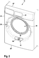
- Fig. 2 shows a schematic view of a front 24 of the washing machine 10, with the front door giving access seals to the washing drum, is not shown here in the sense of better representation of the invention.
- the washing machine basically has an upper side 25 'and an underside 25 ".
- the vertical directions, in particular the directions above and below, are therefore to be understood relative to the upper side 25' and the lower side 25".
- the horizontal direction, in particular the directional indication laterally, is therefore to be understood as perpendicular to the vertical direction.
- the washing machine 10 has a washing machine housing 12, a washing drum 14, a door 16, a filter device 18, a control device 20 and a display device 22.
- the washing drum 14 is arranged in the washing machine housing 12.
- the washing machine housing 12 has an access 28 to the washing drum 14 on the front 24 of the washing machine 10.
- At the entrance 28 is the door 16, in Fig. 2 not shown, pivotally attached laterally in a recess 26 to selectively open or close the access 28.
- the filter device 18 is arranged below the access 28.
- the filter device 18 is preferably arranged on an underside of the access 28.
- the filter device 18 extends from the underside of the access 28 in the direction of the underside 25 ′′ of the washing machine 10.
- the display device 22 is arranged on the front 24 of the washing machine 10 above the access 28.
- the control device 20 is arranged in the washing machine housing 12.
- the control device 20 is preferably arranged in an upper part of the washing machine housing 12, in particular on or in the vicinity of the upper side 25 ′ of the washing machine 10.
- the control device 20 is set up to control components of the washing machine.
- the control device 20 can, for example, be set up to control the operation of the washing machine and / or a display of the display device 22.
- the Figures 3 and 4 show an embodiment of the filter device 18 from Fig. 1 .
- the filter device 18 has a housing 30 and a filter device 32.
- the housing 30 has a water inlet 34 and a water outlet 36.
- the water inlet 34 is in in the vertical direction above the water outlet 36.
- the filter device 32 can be inserted or removed from the housing 30.
- the housing 30 has an opening 31 through which the filter device 32 can be removed or inserted.
- the filter device 32 is inserted into the housing 30.
- the filter device 32 can also have a closing element 44 with which the opening 31 of the housing 30 can be closed.
- a thread can be provided in the closing element 44 and a corresponding counter thread in the opening 31 of the housing 30.
- a bayonet lock can also be provided on the closing element.
- a sealing element for example a sealing ring 52, is preferably provided between the housing 30 and the closing element 44 in order to close the housing 30 with the closing element 44 in a watertight manner.
- the filter device 32 is arranged in the housing 30 at least partially between the water inlet 34 and the water outlet 36 in order to filter the water that flows from the water inlet 34 to the water outlet 36 during operation of the washing machine 10.
- the housing 30 is watertight at least in the area between the water inlet 34 and the water outlet 36.
- the filter device 18 can furthermore have a sensor device 38, which is designed to detect foreign bodies, in particular fluff, lint, microparticles and / or metal, in the filter device 32.
- the sensor device 38 can have, for example, an optical and / or a magnetic sensor.
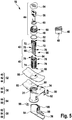
- Fig. 5 is the filter device 18 from the Figures 3 and 4 shown as an exploded view.
- the filter device 32 can have a sieve element 40, an insert element 42 and the closing element 44.
- the closing element 44 can have a base body 46.
- the base body 46 is essentially cylindrical.
- the base body 46 has a thread 50.
- the thread 50 runs in a direction of rotation about an axis of rotation.
- the axis of rotation corresponds to an axis of symmetry of the symmetrical shape of the base body 50.
- the axis of symmetry is preferably aligned in the vertical direction.
- the base body 46 is in the Fig. 5 shown in two views. In the first view it can be seen that the base body can be hollow. The second view shows the underside of the base body on which a projection 48 is arranged. Below the thread 50, a sealing ring 52 can be provided around the cylindrical base body 46 in order to close the housing 30 with the closing element 44 in a watertight manner.
- the closing element 44 can furthermore have a cover 54 with a recess 56, a handle element 58 and a guide element 60.
- the guide element 60 and the handle element 58 are inserted in the hollow base body 46.
- the base body 46 has an open top.
- the lid 54 closes the open top.
- the guide member 60 provides guidance for the handle member 58 in the vertical direction so that the handle member 58 is vertically movable.
- the recess 56 is complementary to the handle element 58.
- the handle element 58 can be partially pulled out of the base body in the vertical direction to actuate the closing element, in particular to rotate the closing element.
- the insert element 42 can have a receptacle 62 for the projection 48.
- the receptacle 62 is arranged on an upper side of the insert element 42.
- the insert element also has a projection 64 on the underside.
- the insert element 42 serves as a connecting element between the sieve element 40 and the closing element 44.
- the insert element 42 preferably has a filter labyrinth 66 which is formed from a multiplicity of webs 68.
- the insert element 42 can furthermore have two opposite recesses, here bores 70, which are arranged laterally on the insert element 42. Furthermore, the insert element 42 can have two opposite lugs 72, which are likewise arranged laterally on the insert element 42.
- the sieve element 40 can have a sieve basket 74.
- the screen basket 74 is preferably at least approximately cylindrical.
- the screen basket 74 has an open top and a closed bottom.
- the strainer basket 74 also has two opposite recesses, here bores 76, which are arranged on the side of the strainer basket 74.
- the sieve element 40 On the upper side of the strainer basket 74, the sieve element 40 has two opposite recesses 78 which serve as receptacles for the lugs 72.
- the sieve element 40 has a receptacle 80 for the projection 64 on the underside of the sieve basket 74.
- the sieve element 40, the insert element 42 and the closing element 44 can be connected to one another in the vertical direction by means of the projections 48, 64 and the receptacles 62, 80 and also via the lugs 72 and the corresponding recesses 78.
- the sieve element 40, the insert element 42 and the closing element 44 can be coupled to one another in a rotationally fixed manner in the direction of rotation.
- the housing 30 can have a first housing part 82, a second housing part 84 and a cover element 86. When assembled, the first housing part 82 is connected to the second housing part 84 and the cover element 86 in order to form the housing 30.
- the first housing part 82 is arranged below the cover element 86 and above the second housing part 84.
- the first housing part 82 and the cover element 86 each have a recess which form the opening 31.
- a counter thread 88 is formed in the opening 31 in the first housing part 82 and is complementary to the thread 50 of the closing element 44.
- the first housing part 82 also has the water inlet 34.
- the water inlet 34 is arranged below the opening 31 on the side of the first housing part 82.
- the second housing part 84 also has the water outlet 36.
- the water outlet 36 is arranged on the bottom of the second housing part 84 laterally on the second housing part 84.
- the sensor device 38 can have a magnetic sensor 90 and / or an optical sensor 94.
- the magnetic sensor 90 is arranged laterally on the first housing part 82.
- Two diodes 92 can be arranged on the sensor 90, preferably a red and a green diode.
- the magnetic sensor 90 is electrically connected to the diodes 92.
- the diodes 92 can, for example, indicate a state of the sensor, in particular whether a metallic foreign body has been detected with the sensor.
- the magnetic sensor 90 can, for example, use an inductively operating principle to detect metal parts.
- an inductively operating principle to detect metal parts.
- use is made of the fact that the relative permeability shifts when a metal part is in the effective range of the sensor.
- the optical sensor 94 is arranged on the second housing part 84.
- the optical sensor 94 can in particular be arranged above or upstream of the water outlet 36.
- the optical sensor 94 can have an optical transmitter 96 and an optical receiver 98.
- the optical transmitter 96 and the optical receiver 98 are arranged laterally on opposite sides of the second housing part 84.
- the optical transmitter 96 sends light pulses to the optical receiver 98 through the second housing part 84.
- the second housing part 84 can, for example, have two opposite bores into which the optical transmitter 96 and the optical receiver 98 are inserted in the assembled state.
- the optical transmitter 96 can have a laser diode, for example.
- the laser diode has the advantage that unwanted light reflections can be avoided.
- the optical receiver 98 can have a photoresistor, for example.
- the light intensity of the light beam from the optical transmitter 96, in particular the intensity of the laser beam from the laser diode, can be measured by means of the photoresistor.
- the sensor device 38 also has an electronic circuit 100 which is arranged on the outside of the second housing half.
- the closing element 44 is arranged in the opening 31 of the housing 30, the thread 50 being fitted or screwed into the counter thread 88.
- the water inlet 34 opens into the housing 30 below the closing element 44.
- the water outlet 36 is arranged laterally at a lower end of the sieve element 40.
- the closing element 44 and the insert element 42 are connected to one another via the projection 48 and the receptacle 62.
- the insert element 42 and the sieve element 40 are connected to one another via the lugs 72 and the recesses 78.
- the projection 64 is inserted into the receptacle 80 in order to rotatably support insert element 42 in the sieve element 40.
- the insert element 42 thus connects the closing element 44 to the sieve element 40.
- the insert element 42 is inserted in particular into the sieve element 40 and extends out of the open upper side of the sieve element 40 in the direction of the underside of the closing element 44.
- the water inlet 34 is in particular arranged between the sieve element 40 and the closing element 44.
- the magnetic sensor 90 is arranged between the sieve element 40 and the closing element 44.
- the magnetic sensor 90 is arranged in particular at the level of the water inlet 34. In other words, the magnetic sensor is arranged upstream of the sieve element 40.
- the optical transmitter 94 is arranged between the water inlet 34 and the water outlet 36. In particular, the optical transmitter 94 is arranged at the level of the sieve element 40.
- the optical transmitter 96 and the optical receiver 98 are arranged on opposite sides of the filter device 32.
- the optical transmitter 96 and the optical receiver 98 are arranged in particular on opposite sides of the sieve element 40.
- the bores 70 and 76 of the sieve element 40 and the insert element 42 are arranged in alignment with the optical transmitter 96 and the optical receiver 98, so that a beam path of a light pulse emitted by the optical transmitter 96 runs through the bores 70, 76 and the optical receiver 98 reached.
- the sensor device 38 is generally designed to detect a foreign body in the filter device 32.
- the magnetic sensor 90 is designed to detect a metallic foreign body in front of the sieve element 40. If there is a metallic foreign body in the effective range of the magnetic sensor 90, it responds inductively to the metallic foreign body. This inductance is measured by the magnetic sensor.
- the sensor device 38 can be configured to determine whether the measured value of the inductance exceeds a predetermined threshold value.
- the optical sensor 94 is designed to detect foreign bodies in the sieve element 40. If there is a foreign body, for example a hair, a fiber, or a lint in the beam path 102 of the optical sensor 94, either the received light intensity is reduced or the light beam is completely blocked, which corresponds to an intensity of zero. This light intensity is measured via the photoresistor.
- the sensor device 38 can be configured to determine whether the measured value of the light intensity falls below a predetermined threshold value.
- the sensor device 38 is designed to generate an analog or digital sensor signal based on the detection of foreign bodies in the filter device.
- the sensor signal contains in particular information about a degree of contamination of the filter device and / or about the detection of a metallic foreign body.
- the information can be either the measured value of the light intensity or the inductance or the result of the determination of whether a predetermined threshold value has been exceeded.
- the control device 20 of the washing machine 10 can be set up to control the washing machine 10 taking into account the sensor signal.
- the sensor signal directly contains the information that a certain degree of contamination of the filter device 32 has been reached or a metallic foreign body in the filter device 32 has been recognized because the corresponding threshold value has been exceeded / undershot, this information can be used to control the washing machine 10 accordingly use.
- the sensor signal only transmits the measured value of the respective sensor.
- the control device 20 can be set up to determine the degree of contamination of the filter device on the basis of the information from the sensor signal, in particular a fill level of the Siebelements is determined. In particular, it can be determined whether the degree of contamination exceeds a certain threshold value. Taking this provision into account, the washing machine can be controlled accordingly.
- the control device 20 can be set up to determine on the basis of the sensor signal whether there is a metallic foreign body in the filter device 32. In particular, it can be determined whether the measured value exceeds a certain threshold value for the inductance, in particular as a result of which the control device 20 determines that a detected foreign body is suitable for damaging the washing machine 10.
- the control device 20 can then be set up to control the display device on the basis of the sensor signal.
- control device can be designed to stop operation of the washing machine if a metallic foreign body has been detected or a certain degree of contamination of the filter device has been reached.
- a user by providing a sensor device for monitoring the filter device, it is possible for a user to receive information that the filter device is to be cleaned by arranging sensors about the machine.
- This information can e.g. B. optically in a display window of the display device by a luminous LED, lettering, etc. or also by an acoustic signal before or after the end of a washing cycle users are available. Alternatively, a degree of contamination can also be shown on an analog display.
- a connectivity module e.g. WiFi
- information can also be transmitted to other receiving devices. If there is a direct connection to the manufacturer and / or its service, the information can also be passed on there, which then informs the user about a required cleaning process via e.g. Informs an app on a user's mobile device.
- washing machine and filter device described make it easy to remove the filter device for cleaning or maintenance. This process is described in more detail below.
- the degree of contamination of the filter is checked. If foreign bodies such as textile particles, fibers, lint, metal parts or other washing residues have accumulated in the filter, the system informs the user of the contamination of the filter on a display of the display device.
- the user can then rotate the filter device by means of the handle element, so that the thread of the closing element is unscrewed from the counter thread of the housing.
- the filter device can then be removed as a whole from the housing for cleaning or maintenance.
Applications Claiming Priority (1)
| Application Number | Priority Date | Filing Date | Title |
|---|---|---|---|
| DE202018106723.0U DE202018106723U1 (de) | 2018-11-26 | 2018-11-26 | Filtervorrichtung für eine Waschmaschine und Waschmaschine |
Publications (2)
| Publication Number | Publication Date |
|---|---|
| EP3656908A1 true EP3656908A1 (fr) | 2020-05-27 |
| EP3656908B1 EP3656908B1 (fr) | 2022-01-05 |
Family
ID=68696346
Family Applications (1)
| Application Number | Title | Priority Date | Filing Date |
|---|---|---|---|
| EP19211506.1A Active EP3656908B1 (fr) | 2018-11-26 | 2019-11-26 | Machine à laver avec un dispositif de filtrage |
Country Status (3)
| Country | Link |
|---|---|
| EP (1) | EP3656908B1 (fr) |
| CN (1) | CN212270465U (fr) |
| DE (2) | DE202018106723U1 (fr) |
Families Citing this family (2)
| Publication number | Priority date | Publication date | Assignee | Title |
|---|---|---|---|---|
| EP3907321A1 (fr) * | 2020-05-05 | 2021-11-10 | emz-Hanauer GmbH & Co. KGaA | Dispositif de piège à corps étranger pour un lave-linge |
| TR202007084A2 (tr) * | 2020-05-06 | 2021-11-22 | Vestel Beyaz Esya San Ve Tic A S | Mikrofiber filtre tertibatı içeren yıkayıcı cihaz. |
Citations (5)
| Publication number | Priority date | Publication date | Assignee | Title |
|---|---|---|---|---|
| EP1751343A1 (fr) | 2004-06-01 | 2007-02-14 | LG Electronics, Inc. | Systeme d'evacuation pour machine a laver a tambour |
| EP2053157A1 (fr) | 2007-10-18 | 2009-04-29 | Electrolux Home Products Corporation N.V. | Sèche-linge utilisant un fluide lavant et équipé d'un ensemble filtrant combiné |
| WO2013047783A1 (fr) * | 2011-09-30 | 2013-04-04 | 株式会社 東芝 | Dispositif de filtre pour machine à laver |
| DE102011086137A1 (de) * | 2011-11-11 | 2013-05-16 | BSH Bosch und Siemens Hausgeräte GmbH | Waschmaschine mit Filtrationsvorrichtung und Verfahren zu ihrem Betrieb |
| DE102014214621A1 (de) * | 2014-07-25 | 2016-01-28 | BSH Hausgeräte GmbH | Haushaltsgerät mit einem Laugenbehälter |
-
2018
- 2018-11-26 DE DE202018106723.0U patent/DE202018106723U1/de active Active
-
2019
- 2019-07-30 DE DE102019120539.5A patent/DE102019120539A1/de not_active Ceased
- 2019-11-22 CN CN201922034469.8U patent/CN212270465U/zh active Active
- 2019-11-26 EP EP19211506.1A patent/EP3656908B1/fr active Active
Patent Citations (5)
| Publication number | Priority date | Publication date | Assignee | Title |
|---|---|---|---|---|
| EP1751343A1 (fr) | 2004-06-01 | 2007-02-14 | LG Electronics, Inc. | Systeme d'evacuation pour machine a laver a tambour |
| EP2053157A1 (fr) | 2007-10-18 | 2009-04-29 | Electrolux Home Products Corporation N.V. | Sèche-linge utilisant un fluide lavant et équipé d'un ensemble filtrant combiné |
| WO2013047783A1 (fr) * | 2011-09-30 | 2013-04-04 | 株式会社 東芝 | Dispositif de filtre pour machine à laver |
| DE102011086137A1 (de) * | 2011-11-11 | 2013-05-16 | BSH Bosch und Siemens Hausgeräte GmbH | Waschmaschine mit Filtrationsvorrichtung und Verfahren zu ihrem Betrieb |
| DE102014214621A1 (de) * | 2014-07-25 | 2016-01-28 | BSH Hausgeräte GmbH | Haushaltsgerät mit einem Laugenbehälter |
Also Published As
| Publication number | Publication date |
|---|---|
| EP3656908B1 (fr) | 2022-01-05 |
| CN212270465U (zh) | 2021-01-01 |
| DE102019120539A1 (de) | 2020-05-28 |
| DE202018106723U1 (de) | 2020-02-28 |
Similar Documents
| Publication | Publication Date | Title |
|---|---|---|
| DE4433842C1 (de) | Vorrichtung zum Spülen in einer Geschirrspülmaschine | |
| DE102017215132A1 (de) | Wäschebehandlungsgerät mit Spektrometer und verbesserter Filtrationsvorrichtung und Verfahren zu seinem Betrieb | |
| DE602005003338T2 (de) | Waschtrockner | |
| DE112009001012T5 (de) | Wäschetrockner | |
| DE10335186A1 (de) | Naß-Trocken-Kombinationsstaubsauger | |
| EP3656908B1 (fr) | Machine à laver avec un dispositif de filtrage | |
| DE19980578C2 (de) | Waschmaschine mit einer Vorrichtung zum Filtern von Schmutz im Waschwasser | |
| DE60025050T2 (de) | Waschmaschine mit einer Entleerungspumpe | |
| DE10046349B4 (de) | Haushaltgerät | |
| EP3712320A1 (fr) | Appareil électroménager à circulation d'eau et son procédé de fonctionnement | |
| EP3553220A1 (fr) | Dispositif capteur et procédé d'analyse d'un liquide et lave-linge | |
| DE102010036940A1 (de) | Fremdkörperabscheider für Waschautomaten | |
| DE202009007469U1 (de) | Abflussvorrichtung angepasst für eine Waschmaschine | |
| EP3473755B1 (fr) | Dispositif de détection et d'élimination de corps étrangers dans ou entre une matière fibreuse | |
| EP3866663A2 (fr) | Lave-vaisselle ménager pourvu d'un système de filtre autonettoyant | |
| EP3249095B1 (fr) | Appareil de lavage pour une salle blanche | |
| DE3603323A1 (de) | Trommelwaschmaschine mit einer mehrteiligen fluessigkeits-leitung | |
| EP3988698A1 (fr) | Lave-linge | |
| EP1845833B1 (fr) | Procede pour faire fonctionner un appareil menager conduisant de l'eau | |
| EP0374411A1 (fr) | Séchoir à linge avec un protége filtre | |
| DE102023103570B3 (de) | Filtrationseinrichtung für ein wasserführendes Haushaltsgerät | |
| EP2018451B1 (fr) | Lave-linge muni d'un flexible de vidange de secours et procédé pour vidanger un tel lave-linge | |
| DE102020207163A1 (de) | Filtereinrichtung zur Filtration von Mikroplastik | |
| EP3663457A1 (fr) | Appareil électroménager conducteur d'eau | |
| DE102009000948A1 (de) | Aufgabeeinrichtung und Verfahren für die Aufgabe eines Testaerosols sowie Vorrichtung zur Filtration eines mit Aerosolen und/oder Stäuben beladenen Gasvolumenstroms |
Legal Events
| Date | Code | Title | Description |
|---|---|---|---|
| PUAI | Public reference made under article 153(3) epc to a published international application that has entered the european phase |
Free format text: ORIGINAL CODE: 0009012 |
|
| STAA | Information on the status of an ep patent application or granted ep patent |
Free format text: STATUS: THE APPLICATION HAS BEEN PUBLISHED |
|
| AK | Designated contracting states |
Kind code of ref document: A1 Designated state(s): AL AT BE BG CH CY CZ DE DK EE ES FI FR GB GR HR HU IE IS IT LI LT LU LV MC MK MT NL NO PL PT RO RS SE SI SK SM TR |
|
| AX | Request for extension of the european patent |
Extension state: BA ME |
|
| STAA | Information on the status of an ep patent application or granted ep patent |
Free format text: STATUS: REQUEST FOR EXAMINATION WAS MADE |
|
| 17P | Request for examination filed |
Effective date: 20200713 |
|
| STAA | Information on the status of an ep patent application or granted ep patent |
Free format text: STATUS: EXAMINATION IS IN PROGRESS |
|
| 17Q | First examination report despatched |
Effective date: 20201201 |
|
| RBV | Designated contracting states (corrected) |
Designated state(s): AL AT BE BG CH CY CZ DE DK EE ES FI FR GB GR HR HU IE IS IT LI LT LU LV MC MK MT NL NO PL PT RO RS SE SI SK SM TR |
|
| GRAP | Despatch of communication of intention to grant a patent |
Free format text: ORIGINAL CODE: EPIDOSNIGR1 |
|
| STAA | Information on the status of an ep patent application or granted ep patent |
Free format text: STATUS: GRANT OF PATENT IS INTENDED |
|
| INTG | Intention to grant announced |
Effective date: 20210630 |
|
| GRAS | Grant fee paid |
Free format text: ORIGINAL CODE: EPIDOSNIGR3 |
|
| GRAA | (expected) grant |
Free format text: ORIGINAL CODE: 0009210 |
|
| STAA | Information on the status of an ep patent application or granted ep patent |
Free format text: STATUS: THE PATENT HAS BEEN GRANTED |
|
| AK | Designated contracting states |
Kind code of ref document: B1 Designated state(s): AL AT BE BG CH CY CZ DE DK EE ES FI FR GB GR HR HU IE IS IT LI LT LU LV MC MK MT NL NO PL PT RO RS SE SI SK SM TR |
|
| REG | Reference to a national code |
Ref country code: GB Ref legal event code: FG4D Free format text: NOT ENGLISH |
|
| REG | Reference to a national code |
Ref country code: CH Ref legal event code: EP |
|
| REG | Reference to a national code |
Ref country code: AT Ref legal event code: REF Ref document number: 1460693 Country of ref document: AT Kind code of ref document: T Effective date: 20220115 |
|
| REG | Reference to a national code |
Ref country code: DE Ref legal event code: R096 Ref document number: 502019003165 Country of ref document: DE |
|
| REG | Reference to a national code |
Ref country code: IE Ref legal event code: FG4D Free format text: LANGUAGE OF EP DOCUMENT: GERMAN |
|
| REG | Reference to a national code |
Ref country code: LT Ref legal event code: MG9D |
|
| REG | Reference to a national code |
Ref country code: NL Ref legal event code: MP Effective date: 20220105 |
|
| PG25 | Lapsed in a contracting state [announced via postgrant information from national office to epo] |
Ref country code: NL Free format text: LAPSE BECAUSE OF FAILURE TO SUBMIT A TRANSLATION OF THE DESCRIPTION OR TO PAY THE FEE WITHIN THE PRESCRIBED TIME-LIMIT Effective date: 20220105 |
|
| PG25 | Lapsed in a contracting state [announced via postgrant information from national office to epo] |
Ref country code: SE Free format text: LAPSE BECAUSE OF FAILURE TO SUBMIT A TRANSLATION OF THE DESCRIPTION OR TO PAY THE FEE WITHIN THE PRESCRIBED TIME-LIMIT Effective date: 20220105 Ref country code: RS Free format text: LAPSE BECAUSE OF FAILURE TO SUBMIT A TRANSLATION OF THE DESCRIPTION OR TO PAY THE FEE WITHIN THE PRESCRIBED TIME-LIMIT Effective date: 20220105 Ref country code: PT Free format text: LAPSE BECAUSE OF FAILURE TO SUBMIT A TRANSLATION OF THE DESCRIPTION OR TO PAY THE FEE WITHIN THE PRESCRIBED TIME-LIMIT Effective date: 20220505 Ref country code: NO Free format text: LAPSE BECAUSE OF FAILURE TO SUBMIT A TRANSLATION OF THE DESCRIPTION OR TO PAY THE FEE WITHIN THE PRESCRIBED TIME-LIMIT Effective date: 20220405 Ref country code: LT Free format text: LAPSE BECAUSE OF FAILURE TO SUBMIT A TRANSLATION OF THE DESCRIPTION OR TO PAY THE FEE WITHIN THE PRESCRIBED TIME-LIMIT Effective date: 20220105 Ref country code: HR Free format text: LAPSE BECAUSE OF FAILURE TO SUBMIT A TRANSLATION OF THE DESCRIPTION OR TO PAY THE FEE WITHIN THE PRESCRIBED TIME-LIMIT Effective date: 20220105 Ref country code: ES Free format text: LAPSE BECAUSE OF FAILURE TO SUBMIT A TRANSLATION OF THE DESCRIPTION OR TO PAY THE FEE WITHIN THE PRESCRIBED TIME-LIMIT Effective date: 20220105 Ref country code: BG Free format text: LAPSE BECAUSE OF FAILURE TO SUBMIT A TRANSLATION OF THE DESCRIPTION OR TO PAY THE FEE WITHIN THE PRESCRIBED TIME-LIMIT Effective date: 20220405 |
|
| PG25 | Lapsed in a contracting state [announced via postgrant information from national office to epo] |
Ref country code: PL Free format text: LAPSE BECAUSE OF FAILURE TO SUBMIT A TRANSLATION OF THE DESCRIPTION OR TO PAY THE FEE WITHIN THE PRESCRIBED TIME-LIMIT Effective date: 20220105 Ref country code: LV Free format text: LAPSE BECAUSE OF FAILURE TO SUBMIT A TRANSLATION OF THE DESCRIPTION OR TO PAY THE FEE WITHIN THE PRESCRIBED TIME-LIMIT Effective date: 20220105 Ref country code: GR Free format text: LAPSE BECAUSE OF FAILURE TO SUBMIT A TRANSLATION OF THE DESCRIPTION OR TO PAY THE FEE WITHIN THE PRESCRIBED TIME-LIMIT Effective date: 20220406 Ref country code: FI Free format text: LAPSE BECAUSE OF FAILURE TO SUBMIT A TRANSLATION OF THE DESCRIPTION OR TO PAY THE FEE WITHIN THE PRESCRIBED TIME-LIMIT Effective date: 20220105 |
|
| PG25 | Lapsed in a contracting state [announced via postgrant information from national office to epo] |
Ref country code: IS Free format text: LAPSE BECAUSE OF FAILURE TO SUBMIT A TRANSLATION OF THE DESCRIPTION OR TO PAY THE FEE WITHIN THE PRESCRIBED TIME-LIMIT Effective date: 20220505 |
|
| REG | Reference to a national code |
Ref country code: DE Ref legal event code: R097 Ref document number: 502019003165 Country of ref document: DE |
|
| PG25 | Lapsed in a contracting state [announced via postgrant information from national office to epo] |
Ref country code: SM Free format text: LAPSE BECAUSE OF FAILURE TO SUBMIT A TRANSLATION OF THE DESCRIPTION OR TO PAY THE FEE WITHIN THE PRESCRIBED TIME-LIMIT Effective date: 20220105 Ref country code: SK Free format text: LAPSE BECAUSE OF FAILURE TO SUBMIT A TRANSLATION OF THE DESCRIPTION OR TO PAY THE FEE WITHIN THE PRESCRIBED TIME-LIMIT Effective date: 20220105 Ref country code: RO Free format text: LAPSE BECAUSE OF FAILURE TO SUBMIT A TRANSLATION OF THE DESCRIPTION OR TO PAY THE FEE WITHIN THE PRESCRIBED TIME-LIMIT Effective date: 20220105 Ref country code: EE Free format text: LAPSE BECAUSE OF FAILURE TO SUBMIT A TRANSLATION OF THE DESCRIPTION OR TO PAY THE FEE WITHIN THE PRESCRIBED TIME-LIMIT Effective date: 20220105 Ref country code: DK Free format text: LAPSE BECAUSE OF FAILURE TO SUBMIT A TRANSLATION OF THE DESCRIPTION OR TO PAY THE FEE WITHIN THE PRESCRIBED TIME-LIMIT Effective date: 20220105 Ref country code: CZ Free format text: LAPSE BECAUSE OF FAILURE TO SUBMIT A TRANSLATION OF THE DESCRIPTION OR TO PAY THE FEE WITHIN THE PRESCRIBED TIME-LIMIT Effective date: 20220105 |
|
| PLBE | No opposition filed within time limit |
Free format text: ORIGINAL CODE: 0009261 |
|
| STAA | Information on the status of an ep patent application or granted ep patent |
Free format text: STATUS: NO OPPOSITION FILED WITHIN TIME LIMIT |
|
| PG25 | Lapsed in a contracting state [announced via postgrant information from national office to epo] |
Ref country code: AL Free format text: LAPSE BECAUSE OF FAILURE TO SUBMIT A TRANSLATION OF THE DESCRIPTION OR TO PAY THE FEE WITHIN THE PRESCRIBED TIME-LIMIT Effective date: 20220105 |
|
| 26N | No opposition filed |
Effective date: 20221006 |
|
| PGFP | Annual fee paid to national office [announced via postgrant information from national office to epo] |
Ref country code: TR Payment date: 20221124 Year of fee payment: 4 Ref country code: IT Payment date: 20221130 Year of fee payment: 4 |
|
| PG25 | Lapsed in a contracting state [announced via postgrant information from national office to epo] |
Ref country code: SI Free format text: LAPSE BECAUSE OF FAILURE TO SUBMIT A TRANSLATION OF THE DESCRIPTION OR TO PAY THE FEE WITHIN THE PRESCRIBED TIME-LIMIT Effective date: 20220105 |
|
| PGFP | Annual fee paid to national office [announced via postgrant information from national office to epo] |
Ref country code: DE Payment date: 20221221 Year of fee payment: 4 |
|
| P01 | Opt-out of the competence of the unified patent court (upc) registered |
Effective date: 20230424 |
|
| PG25 | Lapsed in a contracting state [announced via postgrant information from national office to epo] |
Ref country code: MC Free format text: LAPSE BECAUSE OF FAILURE TO SUBMIT A TRANSLATION OF THE DESCRIPTION OR TO PAY THE FEE WITHIN THE PRESCRIBED TIME-LIMIT Effective date: 20220105 |
|
| REG | Reference to a national code |
Ref country code: CH Ref legal event code: PL |
|
| REG | Reference to a national code |
Ref country code: BE Ref legal event code: MM Effective date: 20221130 |
|
| PG25 | Lapsed in a contracting state [announced via postgrant information from national office to epo] |
Ref country code: LI Free format text: LAPSE BECAUSE OF NON-PAYMENT OF DUE FEES Effective date: 20221130 Ref country code: CH Free format text: LAPSE BECAUSE OF NON-PAYMENT OF DUE FEES Effective date: 20221130 |
|
| PG25 | Lapsed in a contracting state [announced via postgrant information from national office to epo] |
Ref country code: LU Free format text: LAPSE BECAUSE OF NON-PAYMENT OF DUE FEES Effective date: 20221126 |
|
| PG25 | Lapsed in a contracting state [announced via postgrant information from national office to epo] |
Ref country code: IE Free format text: LAPSE BECAUSE OF NON-PAYMENT OF DUE FEES Effective date: 20221126 |
|
| PG25 | Lapsed in a contracting state [announced via postgrant information from national office to epo] |
Ref country code: FR Free format text: LAPSE BECAUSE OF NON-PAYMENT OF DUE FEES Effective date: 20221130 Ref country code: BE Free format text: LAPSE BECAUSE OF NON-PAYMENT OF DUE FEES Effective date: 20221130 |
|
| PG25 | Lapsed in a contracting state [announced via postgrant information from national office to epo] |
Ref country code: HU Free format text: LAPSE BECAUSE OF FAILURE TO SUBMIT A TRANSLATION OF THE DESCRIPTION OR TO PAY THE FEE WITHIN THE PRESCRIBED TIME-LIMIT; INVALID AB INITIO Effective date: 20191126 |
|
| PG25 | Lapsed in a contracting state [announced via postgrant information from national office to epo] |
Ref country code: CY Free format text: LAPSE BECAUSE OF FAILURE TO SUBMIT A TRANSLATION OF THE DESCRIPTION OR TO PAY THE FEE WITHIN THE PRESCRIBED TIME-LIMIT Effective date: 20220105 |
|
| PGFP | Annual fee paid to national office [announced via postgrant information from national office to epo] |
Ref country code: DE Payment date: 20231228 Year of fee payment: 5 |