EP3656048B1 - Procédé de contrôle commande d'une machine électrique tournante pour véhicule automobile - Google Patents
Procédé de contrôle commande d'une machine électrique tournante pour véhicule automobile Download PDFInfo
- Publication number
- EP3656048B1 EP3656048B1 EP18736951.7A EP18736951A EP3656048B1 EP 3656048 B1 EP3656048 B1 EP 3656048B1 EP 18736951 A EP18736951 A EP 18736951A EP 3656048 B1 EP3656048 B1 EP 3656048B1
- Authority
- EP
- European Patent Office
- Prior art keywords
- electric machine
- excitation current
- braking
- rotary electric
- during
- Prior art date
- Legal status (The legal status is an assumption and is not a legal conclusion. Google has not performed a legal analysis and makes no representation as to the accuracy of the status listed.)
- Active
Links
Images

Classifications
-
- H—ELECTRICITY
- H02—GENERATION; CONVERSION OR DISTRIBUTION OF ELECTRIC POWER
- H02P—CONTROL OR REGULATION OF ELECTRIC MOTORS, ELECTRIC GENERATORS OR DYNAMO-ELECTRIC CONVERTERS; CONTROLLING TRANSFORMERS, REACTORS OR CHOKE COILS
- H02P3/00—Arrangements for stopping or slowing electric motors, generators, or dynamo-electric converters
- H02P3/06—Arrangements for stopping or slowing electric motors, generators, or dynamo-electric converters for stopping or slowing an individual dynamo-electric motor or dynamo-electric converter
- H02P3/08—Arrangements for stopping or slowing electric motors, generators, or dynamo-electric converters for stopping or slowing an individual dynamo-electric motor or dynamo-electric converter for stopping or slowing a DC motor
- H02P3/14—Arrangements for stopping or slowing electric motors, generators, or dynamo-electric converters for stopping or slowing an individual dynamo-electric motor or dynamo-electric converter for stopping or slowing a DC motor by regenerative braking
-
- B—PERFORMING OPERATIONS; TRANSPORTING
- B60—VEHICLES IN GENERAL
- B60L—PROPULSION OF ELECTRICALLY-PROPELLED VEHICLES; SUPPLYING ELECTRIC POWER FOR AUXILIARY EQUIPMENT OF ELECTRICALLY-PROPELLED VEHICLES; ELECTRODYNAMIC BRAKE SYSTEMS FOR VEHICLES IN GENERAL; MAGNETIC SUSPENSION OR LEVITATION FOR VEHICLES; MONITORING OPERATING VARIABLES OF ELECTRICALLY-PROPELLED VEHICLES; ELECTRIC SAFETY DEVICES FOR ELECTRICALLY-PROPELLED VEHICLES
- B60L50/00—Electric propulsion with power supplied within the vehicle
- B60L50/10—Electric propulsion with power supplied within the vehicle using propulsion power supplied by engine-driven generators, e.g. generators driven by combustion engines
- B60L50/16—Electric propulsion with power supplied within the vehicle using propulsion power supplied by engine-driven generators, e.g. generators driven by combustion engines with provision for separate direct mechanical propulsion
-
- B—PERFORMING OPERATIONS; TRANSPORTING
- B60—VEHICLES IN GENERAL
- B60L—PROPULSION OF ELECTRICALLY-PROPELLED VEHICLES; SUPPLYING ELECTRIC POWER FOR AUXILIARY EQUIPMENT OF ELECTRICALLY-PROPELLED VEHICLES; ELECTRODYNAMIC BRAKE SYSTEMS FOR VEHICLES IN GENERAL; MAGNETIC SUSPENSION OR LEVITATION FOR VEHICLES; MONITORING OPERATING VARIABLES OF ELECTRICALLY-PROPELLED VEHICLES; ELECTRIC SAFETY DEVICES FOR ELECTRICALLY-PROPELLED VEHICLES
- B60L50/00—Electric propulsion with power supplied within the vehicle
- B60L50/50—Electric propulsion with power supplied within the vehicle using propulsion power supplied by batteries or fuel cells
- B60L50/60—Electric propulsion with power supplied within the vehicle using propulsion power supplied by batteries or fuel cells using power supplied by batteries
- B60L50/61—Electric propulsion with power supplied within the vehicle using propulsion power supplied by batteries or fuel cells using power supplied by batteries by batteries charged by engine-driven generators, e.g. series hybrid electric vehicles
-
- B—PERFORMING OPERATIONS; TRANSPORTING
- B60—VEHICLES IN GENERAL
- B60L—PROPULSION OF ELECTRICALLY-PROPELLED VEHICLES; SUPPLYING ELECTRIC POWER FOR AUXILIARY EQUIPMENT OF ELECTRICALLY-PROPELLED VEHICLES; ELECTRODYNAMIC BRAKE SYSTEMS FOR VEHICLES IN GENERAL; MAGNETIC SUSPENSION OR LEVITATION FOR VEHICLES; MONITORING OPERATING VARIABLES OF ELECTRICALLY-PROPELLED VEHICLES; ELECTRIC SAFETY DEVICES FOR ELECTRICALLY-PROPELLED VEHICLES
- B60L7/00—Electrodynamic brake systems for vehicles in general
- B60L7/10—Dynamic electric regenerative braking
- B60L7/18—Controlling the braking effect
-
- H—ELECTRICITY
- H02—GENERATION; CONVERSION OR DISTRIBUTION OF ELECTRIC POWER
- H02P—CONTROL OR REGULATION OF ELECTRIC MOTORS, ELECTRIC GENERATORS OR DYNAMO-ELECTRIC CONVERTERS; CONTROLLING TRANSFORMERS, REACTORS OR CHOKE COILS
- H02P9/00—Arrangements for controlling electric generators for the purpose of obtaining a desired output
- H02P9/10—Control effected upon generator excitation circuit to reduce harmful effects of overloads or transients, e.g. sudden application of load, sudden removal of load, sudden change of load
-
- B—PERFORMING OPERATIONS; TRANSPORTING
- B60—VEHICLES IN GENERAL
- B60L—PROPULSION OF ELECTRICALLY-PROPELLED VEHICLES; SUPPLYING ELECTRIC POWER FOR AUXILIARY EQUIPMENT OF ELECTRICALLY-PROPELLED VEHICLES; ELECTRODYNAMIC BRAKE SYSTEMS FOR VEHICLES IN GENERAL; MAGNETIC SUSPENSION OR LEVITATION FOR VEHICLES; MONITORING OPERATING VARIABLES OF ELECTRICALLY-PROPELLED VEHICLES; ELECTRIC SAFETY DEVICES FOR ELECTRICALLY-PROPELLED VEHICLES
- B60L2240/00—Control parameters of input or output; Target parameters
- B60L2240/40—Drive Train control parameters
- B60L2240/42—Drive Train control parameters related to electric machines
- B60L2240/425—Temperature
-
- B—PERFORMING OPERATIONS; TRANSPORTING
- B60—VEHICLES IN GENERAL
- B60L—PROPULSION OF ELECTRICALLY-PROPELLED VEHICLES; SUPPLYING ELECTRIC POWER FOR AUXILIARY EQUIPMENT OF ELECTRICALLY-PROPELLED VEHICLES; ELECTRODYNAMIC BRAKE SYSTEMS FOR VEHICLES IN GENERAL; MAGNETIC SUSPENSION OR LEVITATION FOR VEHICLES; MONITORING OPERATING VARIABLES OF ELECTRICALLY-PROPELLED VEHICLES; ELECTRIC SAFETY DEVICES FOR ELECTRICALLY-PROPELLED VEHICLES
- B60L2240/00—Control parameters of input or output; Target parameters
- B60L2240/40—Drive Train control parameters
- B60L2240/52—Drive Train control parameters related to converters
- B60L2240/525—Temperature of converter or components thereof
-
- Y—GENERAL TAGGING OF NEW TECHNOLOGICAL DEVELOPMENTS; GENERAL TAGGING OF CROSS-SECTIONAL TECHNOLOGIES SPANNING OVER SEVERAL SECTIONS OF THE IPC; TECHNICAL SUBJECTS COVERED BY FORMER USPC CROSS-REFERENCE ART COLLECTIONS [XRACs] AND DIGESTS
- Y02—TECHNOLOGIES OR APPLICATIONS FOR MITIGATION OR ADAPTATION AGAINST CLIMATE CHANGE
- Y02T—CLIMATE CHANGE MITIGATION TECHNOLOGIES RELATED TO TRANSPORTATION
- Y02T10/00—Road transport of goods or passengers
- Y02T10/60—Other road transportation technologies with climate change mitigation effect
- Y02T10/62—Hybrid vehicles
-
- Y—GENERAL TAGGING OF NEW TECHNOLOGICAL DEVELOPMENTS; GENERAL TAGGING OF CROSS-SECTIONAL TECHNOLOGIES SPANNING OVER SEVERAL SECTIONS OF THE IPC; TECHNICAL SUBJECTS COVERED BY FORMER USPC CROSS-REFERENCE ART COLLECTIONS [XRACs] AND DIGESTS
- Y02—TECHNOLOGIES OR APPLICATIONS FOR MITIGATION OR ADAPTATION AGAINST CLIMATE CHANGE
- Y02T—CLIMATE CHANGE MITIGATION TECHNOLOGIES RELATED TO TRANSPORTATION
- Y02T10/00—Road transport of goods or passengers
- Y02T10/60—Other road transportation technologies with climate change mitigation effect
- Y02T10/64—Electric machine technologies in electromobility
-
- Y—GENERAL TAGGING OF NEW TECHNOLOGICAL DEVELOPMENTS; GENERAL TAGGING OF CROSS-SECTIONAL TECHNOLOGIES SPANNING OVER SEVERAL SECTIONS OF THE IPC; TECHNICAL SUBJECTS COVERED BY FORMER USPC CROSS-REFERENCE ART COLLECTIONS [XRACs] AND DIGESTS
- Y02—TECHNOLOGIES OR APPLICATIONS FOR MITIGATION OR ADAPTATION AGAINST CLIMATE CHANGE
- Y02T—CLIMATE CHANGE MITIGATION TECHNOLOGIES RELATED TO TRANSPORTATION
- Y02T10/00—Road transport of goods or passengers
- Y02T10/60—Other road transportation technologies with climate change mitigation effect
- Y02T10/70—Energy storage systems for electromobility, e.g. batteries
-
- Y—GENERAL TAGGING OF NEW TECHNOLOGICAL DEVELOPMENTS; GENERAL TAGGING OF CROSS-SECTIONAL TECHNOLOGIES SPANNING OVER SEVERAL SECTIONS OF THE IPC; TECHNICAL SUBJECTS COVERED BY FORMER USPC CROSS-REFERENCE ART COLLECTIONS [XRACs] AND DIGESTS
- Y02—TECHNOLOGIES OR APPLICATIONS FOR MITIGATION OR ADAPTATION AGAINST CLIMATE CHANGE
- Y02T—CLIMATE CHANGE MITIGATION TECHNOLOGIES RELATED TO TRANSPORTATION
- Y02T10/00—Road transport of goods or passengers
- Y02T10/60—Other road transportation technologies with climate change mitigation effect
- Y02T10/7072—Electromobility specific charging systems or methods for batteries, ultracapacitors, supercapacitors or double-layer capacitors
Definitions
- the present invention relates to a method for controlling a rotating electrical machine of a motor vehicle.
- the invention relates more particularly to a method for controlling a rotating electrical machine making it possible to recover part of the kinetic energy of the vehicle during braking or slowing down phases and to convert it into electrical energy.
- the present invention finds a particularly interesting application in the field of alternators or alternator-starters for motor vehicles.
- New CO2 emission control standards now require more stringent management of a vehicle's electrical system. As a result, car manufacturers are seeking innovative solutions to help transition to cleaner vehicles.
- This mode of energy recovery during braking phases is classically called regenerative or regenerative braking.
- the document WO 2015/018993 describes a device for controlling regenerative braking of a vehicle equipped with a first braking means and a second braking means and designed to generate a braking instruction regenerative based on a braking request signal from a driver's pedal of the vehicle.
- the documents US 2006/192533 A1 , EP 2 039 559 A1 And US 2006/142115 A1 also disclose regenerative braking techniques.
- the invention seeks to propose an innovative solution for managing the alternator during regenerative braking, optimizing both the recharging of the vehicle battery while avoiding excessive use of the voltage regulation means.
- the invention proposes a method for controlling a rotating electrical machine, as defined in independent claim 1.
- the invention also relates to a rotating electrical machine as defined in independent claim 5.
- the rotating electrical machine includes a temperature sensor.
- the temperature sensor is a diode with a "thermocoupled" thermal measurement connected to the voltage regulator.
- a Hall effect sensor makes it possible to give an estimate of the flow current which makes it possible to deduce the diode temperature via the phase voltage value information + machine current and a map integrated into the regulator.
- FIG. 1 illustrates the interaction between different elements of a motor vehicle during a regenerative braking phase with management carried out by the control-command method according to the invention.
- a motor vehicle comprises, in particular, an electronic control unit 2, known by the abbreviation ECU (for “Engine” Electronic Control Unit in English) electrically connected to the rotating electrical machine 1 which is directly connected to a battery 3.
- ECU for “Engine” Electronic Control Unit in English
- the electronic control unit 2 constantly receives information about the vehicle status as well as the status of the various driver controls via various sensors present in the vehicle.
- the electronic control unit 2 is also capable of controlling numerous actuators based on the vehicle status information.
- the electronic control unit 2 receives a large amount of information, including information on the actuation of the brake pedal or on the slowing down of the vehicle.
- the rotating electrical machine 1 is typically a motor vehicle alternator, for example a claw alternator, comprising a voltage regulator 11 and an electronic module 12 capable of rectifying, regulating and controlling the quantity of current delivered to the battery 3, in particular as a function of the voltage information U batt of the battery 3.
- a motor vehicle alternator for example a claw alternator
- an electronic module 12 capable of rectifying, regulating and controlling the quantity of current delivered to the battery 3, in particular as a function of the voltage information U batt of the battery 3.
- FIG. 2 illustrates the main steps of the control-command method 100 according to the invention.
- the voltage regulator 11 receives information, referenced “info_kenage” on the braking state of the motor vehicle.
- info_kenage we mean both an action by the driver consisting of actuating the brake pedal and a slowing down of the vehicle when the driver no longer actuates the accelerator pedal.
- This “braking_info” information is sent continuously by the electronic control unit 2 to the voltage regulator 11.
- This “braking_info” information is typically information using binary numbering coding on one or more bits, for example “0” means that the vehicle is not braking and “1” that the vehicle is braking.
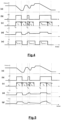
- This information is represented by the graphs (b) on the figures 3 to 5 This information corresponds, in binary coding, to the different braking periods carried out by the driver during the scenarios represented in graphs (a) which illustrate the vehicle speed as a function of time.
- a second step 102 when the voltage regulator 11 detects a change in state of the braking information “info_freinage”, and more specifically a change in state from “0” to “1”, the voltage regulator 11 triggers a timer (graphs (c)) at time t 0 .
- a third step 103 occurring simultaneously with the second step 102, when the change of state is detected by the voltage regulator 11, the latter authorizes the alternator 1 to deliver or output a maximum current C MX .
- This step is notably illustrated by the graphs (d) which illustrate the quantity of current output by the alternator 1 as a function of time. The output of an excitation current is carried out during the duration t d which corresponds, in the embodiment illustrated in Figure 3 , entirely during the vehicle braking phase.
- the maximum current C MX corresponds to the maximum current that alternator 1 is technically capable of delivering.
- the duration of maximum current flow is limited by a maximum activation duration T dmax which is counted from the triggering of the timer at time t 0 .
- the regulator of voltage 11 authorizes a current flow as long as the duration of the braking phase is less than the maximum activation duration T dmax set in the voltage regulator 11.
- the voltage regulator 11 authorizes the flow of a maximum excitation current only during the period of time corresponding to the maximum activation duration T dmax .
- a fourth step 104 the voltage regulator 11 blocks, for a certain duration t b , the possibility of delivering a maximum excitation current during a new braking phase. This blocking occurs at the end of a current flow period t d occurring during a previous braking phase.
- This blocking allows a rest period t b to be imposed during which it is impossible for the alternator to deliver a maximum excitation current again during a new braking phase.
- This rest or blocking period ensures sufficient cooling of the components, particularly the rectifier diodes/Mosfet and the voltage regulator.
- this rest duration t b is fixed and configurable in the electronic module 12 of the voltage regulator 11 according to the characteristics of the alternator 1.
- the maximum activation duration of the alternator is limited by the temperature of the critical components.
- the regulator 11 stops the flow of excitation current.
- the curve (g) of the Figure 5 illustrates an example of variation in the temperature of critical components as a function of time, during a speed variation scenario illustrated by curve (a).
- the activation duration is limited by the increase in temperature which becomes equal to the temperature setpoint T cons .
- This temperature information is received directly by the regulator via a temperature probe, or a system allowing the acquisition of the temperature of critical components such as for example a thermocouple positioned on a rectifier diode, or a system for estimating the temperature via a Hall effect sensor to know the flow current of the machine, a measurement of the phase voltage as well as a mapping of the voltage drop of the diodes or rectifier devices in the regulator.
- a temperature probe or a system allowing the acquisition of the temperature of critical components such as for example a thermocouple positioned on a rectifier diode, or a system for estimating the temperature via a Hall effect sensor to know the flow current of the machine, a measurement of the phase voltage as well as a mapping of the voltage drop of the diodes or rectifier devices in the regulator.
- This third embodiment of the control-command method 100 makes it possible in particular to save time for recovering electrical energy during regenerative braking by taking into account the temperature of the components.
Landscapes
- Engineering & Computer Science (AREA)
- Power Engineering (AREA)
- Transportation (AREA)
- Mechanical Engineering (AREA)
- Life Sciences & Earth Sciences (AREA)
- Sustainable Development (AREA)
- Sustainable Energy (AREA)
- Control Of Eletrric Generators (AREA)
- Electric Propulsion And Braking For Vehicles (AREA)
Description
- La présente invention concerne un procédé de contrôle-commande d'une machine électrique tournante de véhicule automobile.
- L'invention concerne plus particulièrement un procédé de contrôle-commande d'une machine électrique tournante permettant de récupérer une partie de l'énergie cinétique du véhicule lors des phases de freinage, ou de ralentissement, et de la convertir en énergie électrique.
- La présente invention trouve une application particulièrement intéressante dans le domaine des alternateurs ou d'alterno-démarreurs de véhicule automobile.
- Les nouvelles normes de contrôle d'émission de CO2 imposent désormais une gestion accrue du circuit électrique du véhicule. En conséquence, les constructeurs automobiles sont à la recherche de solutions innovantes permettant de réaliser une transition vers des véhicules automobiles plus propres.
- Dans le domaine des véhicules automobile, il est désormais connu de découpler la machine électrique tournante (i.e. l'alternateur) du moteur lors des phases d'accélération et de la coupler de nouveau lors des phases de freinage pour freiner davantage le véhicule et/ou pour transformer une partie de l'énergie cinétique du moteur en énergie électrique permettant notamment de recharger la batterie du véhicule.
- Ce mode de récupération d'énergie pendant les phases de freinage est classiquement appelé freinage régénératif ou récupératif.
- Le document
WO 2015/018993 décrit un dispositif de contrôle de freinage régénératif d'un véhicule équipé d'un premier moyen de freinage et d'un deuxième moyen de freinage et conçu pour générer une consigne de freinage régénératif en fonction d'un signal de requête de freinage issu d'une pédale conducteur du véhicule. Les documentsUS 2006/192533 A1 ,EP 2 039 559 A1 etUS 2006/142115 A1 divulguent également des techniques de freinage récupératif. - Dans ce contexte, l'invention cherche à proposer une solution innovante de gestion de l'alternateur lors d'un freinage régénératif optimisant à la fois le rechargement de la batterie du véhicule tout en évitant une sollicitation trop importante des moyens de régulation de tension.
- A cette fin, l'invention propose un procédé de contrôle-commande d'une machine électrique tournante, telle que définie dans la revendication indépendante 1.
- Outre les caractéristiques qui viennent d'être évoquées dans le paragraphe précédent, le procédé de contrôle-commande selon l'invention peut présenter une ou plusieurs caractéristiques complémentaires parmi les suivantes, considérées individuellement ou selon toutes les combinaisons techniquement possibles :
- l'étape de débit du courant d'excitation prédéterminé est limitée dans le temps par une durée maximale d'activation ajustable par programmation en fonction des besoins et contraintes système (température, batterie, fiabilité...) ;
- le procédé comporte une étape de blocage pendant une durée déterminée du débit du courant d'excitation de la fonction freinage régénératif prédéterminé par le régulateur de tension ;
- ladite étape de blocage intervient dès la fin de l'étape de débit d'un courant d'excitation prédéterminé ;
- la durée maximale d'activation pendant laquelle le courant d'excitation prédéterminé est débité augmente avec l'augmentation du courant d'excitation moyen débité par la machine électrique tournante.
- L'invention a également pour objet une machine électrique tournante telle que définie dans la revendication indépendante 5.
- Avantageusement, la machine électrique tournante comporte un capteur de température.
- Avantageusement, le capteur de température est une diode comportant une mesure thermique « thermocouplée » connecté au régulateur de tension. Avantageusement, un capteur à effet hall permet de donner une estimation du courant de débit qui permet de déduire la température diode via les informations de valeur de tension phase + courant de machine et une cartographie intégré dans le régulateur.
- L'invention et ses différentes applications seront mieux comprises à la lecture de la description qui suit et à l'examen des figures qui l'accompagnent.
- Les figures sont présentées à titre indicatif et nullement limitatif de l'invention.
- La
figure 1 illustre l'interaction entre la machine électrique tournante, le boitier contrôle-moteur ainsi que la batterie d'un véhicule automobile lors d'un freinage régénératif. - La
figure 2 illustre un schéma synoptique illustrant les principales étapes du procédé de contrôle commande selon l'invention. - La
figure 3 illustre un premier exemple de fonctionnement du procédé de contrôle-commande selon l'invention lors d'un premier scénario de freinage. - La
figure 4 illustre un deuxième exemple de fonctionnement du procédé de contrôle-commande selon l'invention lors d'un deuxième scénario de freinage. - La
figure 5 illustre un troisième exemple de fonctionnement du procédé de contrôle-commande lors du troisième scénario de freinage illustré précédemment à lafigure 4 . - La
figure 1 illustre l'interaction entre différents éléments d'un véhicule automobile lors d'une phase de freinage régénératif avec une gestion réalisée par le procédé de contrôle-commande selon l'invention. Classiquement, un véhicule automobile comporte, notamment, une unité de commande électronique 2, connu sous l'abréviation ECU (pour « Engine » Electronic Control Unit en langue anglaise) reliée électriquement à la machine électrique tournante 1 qui est directement connectée à une batterie 3. - Classiquement, l'unité de commande électronique 2 reçoit constamment des informations sur l'état du véhicule ainsi que sur l'état des différentes commandes du conducteur via différents capteurs présents dans le véhicule. L'unité de commande électronique 2 est également capable de commander de nombreux actionneurs en fonction des informations de l'état de véhicule.
- Ainsi, l'unité de commande électronique 2 reçoit une grande quantité d'informations, dont notamment une information sur l'actionnement de la pédale de frein ou encore sur le ralentissement du véhicule.
- La machine électrique tournante 1 est typiquement un alternateur de véhicule automobile, par exemple à griffe, comportant un régulateur de tension 11 et un module électronique 12 apte à redresser, réguler et contrôler la quantité de courant délivré à la batterie 3, notamment en fonction de l'information de tension Ubatt de la batterie 3.
- La
figure 2 illustre les principales étapes du procédé de contrôle-commande 100 selon l'invention. - Selon une première étape 101 du procédé 100, le régulateur de tension 11 reçoit une information, référencée « info_freinage » sur l'état de freinage du véhicule automobile. On entend par freinage du véhicule aussi bien une action du conducteur consistant à actionner la pédale de frein qu'un ralentissement du véhicule opéré lorsque le conducteur n'actionne plus la pédale d'accélérateur.
- Cette information « info_freinage » est envoyée en continue par l'unité de commande électronique 2 au régulateur de tension 11. Cette information « info_freinage » est typiquement une information utilisant un codage de numération binaire sur un ou plusieurs bits, par exemple « 0 » signifie que le véhicule ne freine pas et « 1 » que le véhicule freine. Cette information est représentée par les graphiques (b) sur les
figures 3 à 5 . Cette information correspond, en codage binaire, aux différentes périodes de freinage réalisées par le conducteur lors des scénarios représentés aux graphiques (a) qui illustrent la vitesse du véhicule en fonction du temps. - Lors d'une deuxième étape 102, lorsque le régulateur de tension 11 détecte un changement d'état de l'information de freinage « info_freinage », et plus spécifiquement un changement d'état de « 0 » à « 1 », le régulateur de tension 11 déclenche un minuteur (graphiques (c)) à l'instant t0.
- Dans une troisième étape 103, intervenant simultanément avec la deuxième étape 102, lorsque le changement d'état est détecté par le régulateur de tension 11, celui-ci autorise l'alternateur 1 à délivrer ou à débiter un courant maximal CMX. Cette étape est notamment illustrée par les graphiques (d) qui illustrent la quantité du courant débitée par l'alternateur 1 en fonction du temps. Le débit d'un courant d'excitation est réalisé pendant la durée td qui correspond, dans le mode de réalisation illustré à la
figure 3 , entièrement à la phase de freinage du véhicule. - Le courant maximal CMX correspond au courant maximal que l'alternateur 1 est capable techniquement de débiter.
- Durant cette troisième étape, la durée de débit de courant maximal est limitée par une durée maximale d'activation Tdmax qui est décompté à partir du déclenchement du minuteur à l'instant t0. Plus précisément, le régulateur de tension 11 autorise un débit de courant tant que la durée de la phase de freinage est inférieure à la durée maximale d'activation Tdmax paramétrée dans le régulateur de tension 11. Ainsi, lorsque la phase de freinage a une durée supérieure à la durée maximale d'activation Tdmax alors, le régulateur de tension 11 autorise le débit d'un courant d'excitation maximal uniquement pendant la période de temps correspondant à la durée maximale d'activation Tdmax.
- Dans une quatrième étape 104, le régulateur de tension 11 bloque, pendant une certaine durée tb, la possibilité de débiter un courant d'excitation maximum pendant une nouvelle phase de freinage. Ce blocage intervient dès la fin d'une période de débit de courant td intervenue lors d'une phase de freinage précédente.
- Ce blocage permet d'imposer une période de temps de repos tb pendant laquelle il est impossible pour l'alternateur de débiter de nouveau un courant d'excitation maximum pendant une nouvelle phase de freinage. Cette durée de repos ou de blocage permet de s'assurer d'un refroidissement suffisant des composants et notamment des diodes/Mosfet de redressement et du régulateur de tension.
- Selon un premier mode de réalisation, cette durée de repos tb est fixe et paramétrable dans le module électronique 12 du régulateur de tension 11 en fonction des caractéristiques de l'alternateur 1.
- Selon une variante de réalisation, cette durée de repos tb est paramétrable en fonction de la durée de débit du courant d'excitation lors du précédent freinage. Ainsi, si lors d'un freinage précédent, la durée du débit du courant d'excitation était inférieure à la durée d'activation maximale alors le régulateur de tension 11 peut autoriser une nouvelle phase de débit de courant d'excitation en prenant en compte les différentes caractéristiques (temps, puissance) de la précédente phase de débit de courant lors d'un freinage régénératif.
- Selon un deuxième mode de réalisation illustré plus spécifiquement à la
figure 4 , il est également possible de paramétrer de manière variable la durée maximale d'activation tdmax durant laquelle le courant d'excitation est maximal et permet à l'alternateur 1 de débiter un courant maximal CMX. - Dans ce premier mode de réalisation, cette durée maximale d'activation Tdmax est paramétrable en fonction du courant moyen débité par l'alternateur avant une phase de freinage régénératif. Ainsi, si l'alternateur 1 se trouve dans un état thermique élevé suite à un débit important au préalable, par exemple par la consommation électrique de différents organes présents dans le véhicule, alors il est possible d'ajuster cette durée maximale d'activation Tdmax2 par rapport à une valeur par défaut Tdmax1 qui présente une durée plus faible. La valeur par défaut Tdmax1 correspond par exemple à la durée maximale d'activation lorsque l'alternateur 1 est dans un état « froid » avec très peu de débit de courant au préalable. Ainsi, de manière générale la durée maximale d'activation Tdmax augmente avec l'augmentation du courant d'excitation moyen débité par l'alternateur 1.
- Selon un troisième mode de réalisation non revendiqué et illustré plus spécifiquement à la
figure 5 , il est également envisagé de paramétrer de manière variable la durée d'activation Tdmax directement en fonction de la température des composants critiques comme notamment les diodes ou du régulateur 11. Dans ce mode de réalisation, la durée maximale d'activation de l'alternateur est limitée par la température des composants critiques. Ainsi dès lors que la température des composants critiques atteint une valeur égale à une température consigne critique, le régulateur 11 stoppe le débit de courant d'excitation. La courbe (g) de lafigure 5 illustre un exemple de variation de la température des composants critiques en fonction du temps, lors d'un scénario de variation de vitesse illustrée par la courbe (a). Ainsi, lors du troisième freinage, la durée d'activation est limitée par la hausse de la température qui devient égale à la valeur consigne de température Tcons. Cette information de température est reçue directement par le régulateur par l'intermédiaire d'une sonde de température, ou un système permettant l'acquisition de la température des composants critiques comme par exemple un thermocouple positionné sur une diode de redressement, ou un système permettant d'estimer la température via un capteur à effet Hall pour connaître le courant de débit de la machine, une mesure de la tension de phase ainsi qu'une cartographie de la chute de tension des diodes ou organes de redressement dans le régulateur. - Ce troisième mode de réalisation du procédé de contrôle-commande 100 permet notamment de ménager le temps de récupération de l'énergie électrique lors d'un freinage régénératif en prenant en compte la température des composants.
Claims (8)
- Procédé de contrôle-commande (100) d'une machine électrique tournante (1) pour véhicule automobile permettant de récupérer une partie de l'énergie cinétique du véhicule lors des phases de freinage ou de ralentissement et de la convertir en énergie électrique, ladite machine tournante (1) comportant un régulateur de tension (11), ledit procédé comportant :- une étape de réception (101) en continue d'une information concernant une phase de freinage régénératif dudit véhicule,- une étape de débit (103) d'un courant d'excitation prédéterminé par ledit régulateur de tension (11) durant cette phase de freinage régénératif.l'étape de débit du courant prédéterminé étant limitée dans le temps par une durée maximale d'activation (Tdmax),caractérisé en ce que la durée maximale d'activation (Tdmax) pendant laquelle le courant d'excitation prédéterminé est débité est fonction du courant d'excitation moyen débité par la machine électrique tournante (1) avant une phase de freinage régénératif.
- Procédé de contrôle-commande (100) selon la revendication précédente, caractérisé en ce qu'il comporte une étape de blocage (104) pendant une durée déterminée (tb) du débit du courant d'excitation prédéterminé par le régulateur de tension (11).
- Procédé de contrôle-commande (100) selon la revendication précédente, caractérisé en ce que ladite étape de blocage (104) intervient dès la fin de l'étape de débit (103) d'un courant d'excitation.
- Procédé de contrôle-commande (100) selon l'une quelconque des revendications précédentes, caractérisé en ce que la durée maximale d'activation (Tdmax) pendant laquelle le courant d'excitation prédéterminé est débité augmente avec l'augmentation du courant d'excitation moyen débité par la machine électrique tournante (1).
- Machine électrique tournante (1) comportant des moyens pour réaliser une fonction de freinage régénératif dans un véhicule automobile, caractérisée en ce qu'elle comporte un régulateur de tension (11) mettant en œuvre le procédé selon l'une quelconque des revendications précédentes.
- Machine électrique tournante selon la revendication 5, caractérisée en ce qu'elle comporte un capteur de température (12).
- Machine électrique tournante (1) selon la revendication 6, caractérisée en ce que le capteur de température (12) est une diode comportant une mesure thermique connecté au régulateur de tension. (11).
- Machine électrique tournante (1) selon la revendication 6, caractérisée en ce que le capteur de température (12) est constitué d'un capteur à effet hall permettant de donner une estimation du courant de débit pour en déduire la température.
Applications Claiming Priority (2)
| Application Number | Priority Date | Filing Date | Title |
|---|---|---|---|
| FR1756729A FR3069120B1 (fr) | 2017-07-17 | 2017-07-17 | Procede de controle- commande d'une machine electrique tournante, notamment pour vehicule automobile |
| PCT/EP2018/068844 WO2019016050A1 (fr) | 2017-07-17 | 2018-07-11 | Procede de controle commande d'une machine electrique tournante, notamment pour vehicule automobile |
Publications (2)
| Publication Number | Publication Date |
|---|---|
| EP3656048A1 EP3656048A1 (fr) | 2020-05-27 |
| EP3656048B1 true EP3656048B1 (fr) | 2025-03-12 |
Family
ID=60627716
Family Applications (1)
| Application Number | Title | Priority Date | Filing Date |
|---|---|---|---|
| EP18736951.7A Active EP3656048B1 (fr) | 2017-07-17 | 2018-07-11 | Procédé de contrôle commande d'une machine électrique tournante pour véhicule automobile |
Country Status (3)
| Country | Link |
|---|---|
| EP (1) | EP3656048B1 (fr) |
| FR (1) | FR3069120B1 (fr) |
| WO (1) | WO2019016050A1 (fr) |
Family Cites Families (4)
| Publication number | Priority date | Publication date | Assignee | Title |
|---|---|---|---|---|
| JP2006182274A (ja) * | 2004-12-28 | 2006-07-13 | Denso Corp | ロックアップクラッチ装備車両の回生制御装置 |
| JP2006211734A (ja) * | 2005-01-25 | 2006-08-10 | Denso Corp | トルク検出装置 |
| JP4179352B2 (ja) * | 2006-07-10 | 2008-11-12 | トヨタ自動車株式会社 | 車両の電力制御装置 |
| FR3009523B1 (fr) * | 2013-08-06 | 2015-08-07 | Renault Sa | Controle du freinage regeneratif dans un vehicule electrique ou hybride |
-
2017
- 2017-07-17 FR FR1756729A patent/FR3069120B1/fr active Active
-
2018
- 2018-07-11 WO PCT/EP2018/068844 patent/WO2019016050A1/fr not_active Ceased
- 2018-07-11 EP EP18736951.7A patent/EP3656048B1/fr active Active
Also Published As
| Publication number | Publication date |
|---|---|
| FR3069120B1 (fr) | 2024-08-16 |
| FR3069120A1 (fr) | 2019-01-18 |
| EP3656048A1 (fr) | 2020-05-27 |
| WO2019016050A1 (fr) | 2019-01-24 |
Similar Documents
| Publication | Publication Date | Title |
|---|---|---|
| EP2812993B1 (fr) | Système et procéde de commande de l'alimentation d'une machine électrique en fonction de la température | |
| EP3146626B1 (fr) | Machine electrique tournante pour vehicule automobile | |
| FR3009869A1 (fr) | Procede de detection d'une deconnexion de batterie d'alimentation d'un vehicule automobile | |
| FR2996703A1 (fr) | Procede de recuperation d'energie electrique avec lissage de tension sur un reseau electrique embarque | |
| EP4441862B1 (fr) | Procede de refroidissement optimise d'une batterie de vehicule electrique ou hybride | |
| WO2011030024A1 (fr) | Procede de determination d'un etat de fonctionnement de moyens de stockage d'energie electrique constitues d'au moins un supercondensateur | |
| FR3069120A1 (fr) | Procede de controle- commande d'une machine electrique tournante, notamment pour vehicule automobile | |
| EP4532246B1 (fr) | Procédé de surveillance d'un couple moteur d'une machine électrique de traction | |
| EP3947933B1 (fr) | Procede de diagnostic d'un systeme de refroidissement d'un circuit electrique de propulsion | |
| FR2929712A1 (fr) | Appareil et procede de detection d'un etat d'interruption de fonctionnement d'un generateur de puissance d'un vehicule | |
| WO2020115427A1 (fr) | Système de contrôle d'une unité de traitement et de génération d'air dans un véhicule de transport ferroviaire | |
| EP2628234A1 (fr) | Procede de recharge d'un module supercondensateur d'un vehicule automobile et vehicule automobile correspondant | |
| FR3136612A1 (fr) | Surveillance par redondance du fonctionnement de détecteurs d’une machine motrice électrique d’un véhicule | |
| EP3361087A1 (fr) | Système et procédé de repositionnement de rotor de moteur thermique | |
| EP2239454A1 (fr) | Procédé de protection thermique d'un système d'arrêt/relance automatique de moteur thermique et système l'utilisant | |
| FR2594273A1 (fr) | Dispositif de commande d'un alternateur de vehicule automobile | |
| FR2967784A1 (fr) | Detection de la deconnexion d'une batterie | |
| FR3074770A1 (fr) | Procede de generation de sensations de conduite | |
| FR2977325A1 (fr) | Procede et dispositif de controle du rechargement d'une batterie de vehicule, pour optimiser la recuperation d'energie cinetique | |
| WO2013083902A2 (fr) | Procede et systeme de regulation d'un alternateur de vehicule automobile, et alternateur de vehiculle automobile comprenant un tel systeme | |
| EP3646426B1 (fr) | Procede de protection des composants d'un module electronique de puissance d'un systeme a alterno-demarreur et systeme mettant en oeuvre ce procede | |
| FR3081626A1 (fr) | Procede de pilotage d'une recharge d'un dispositif de stockage d'energie pour un organe electrique de vehicule automobile | |
| FR2992788A1 (fr) | Procede et dispositif de controle d'un producteur d'energie electrique et de moyens de stockage d'energie electrique d'un systeme, par pilotage de leurs consignes de courant | |
| WO2026017554A1 (fr) | Procédé de surveillance de l'état d'au moins un câble lié au fonctionnement d'un moteur roue d'un véhicule | |
| FR3120441A1 (fr) | Procede de detection de panne d’un actionneur de frein et dispositif de detection de panne associe |
Legal Events
| Date | Code | Title | Description |
|---|---|---|---|
| STAA | Information on the status of an ep patent application or granted ep patent |
Free format text: STATUS: UNKNOWN |
|
| STAA | Information on the status of an ep patent application or granted ep patent |
Free format text: STATUS: THE INTERNATIONAL PUBLICATION HAS BEEN MADE |
|
| PUAI | Public reference made under article 153(3) epc to a published international application that has entered the european phase |
Free format text: ORIGINAL CODE: 0009012 |
|
| STAA | Information on the status of an ep patent application or granted ep patent |
Free format text: STATUS: REQUEST FOR EXAMINATION WAS MADE |
|
| 17P | Request for examination filed |
Effective date: 20191217 |
|
| AK | Designated contracting states |
Kind code of ref document: A1 Designated state(s): AL AT BE BG CH CY CZ DE DK EE ES FI FR GB GR HR HU IE IS IT LI LT LU LV MC MK MT NL NO PL PT RO RS SE SI SK SM TR |
|
| AX | Request for extension of the european patent |
Extension state: BA ME |
|
| DAV | Request for validation of the european patent (deleted) | ||
| DAX | Request for extension of the european patent (deleted) | ||
| STAA | Information on the status of an ep patent application or granted ep patent |
Free format text: STATUS: EXAMINATION IS IN PROGRESS |
|
| 17Q | First examination report despatched |
Effective date: 20210528 |
|
| P01 | Opt-out of the competence of the unified patent court (upc) registered |
Effective date: 20230528 |
|
| RAP1 | Party data changed (applicant data changed or rights of an application transferred) |
Owner name: VALEO ELECTRIFICATION |
|
| RIC1 | Information provided on ipc code assigned before grant |
Ipc: B60L 50/61 20190101ALN20240715BHEP Ipc: B60L 50/16 20190101ALN20240715BHEP Ipc: B60L 7/18 20060101ALN20240715BHEP Ipc: B60L 7/22 20060101ALI20240715BHEP Ipc: H02P 3/14 20060101ALI20240715BHEP Ipc: H02P 9/10 20060101AFI20240715BHEP |
|
| GRAP | Despatch of communication of intention to grant a patent |
Free format text: ORIGINAL CODE: EPIDOSNIGR1 |
|
| STAA | Information on the status of an ep patent application or granted ep patent |
Free format text: STATUS: GRANT OF PATENT IS INTENDED |
|
| RIC1 | Information provided on ipc code assigned before grant |
Ipc: B60L 50/61 20190101ALN20240830BHEP Ipc: B60L 50/16 20190101ALN20240830BHEP Ipc: B60L 7/18 20060101ALN20240830BHEP Ipc: B60L 7/22 20060101ALI20240830BHEP Ipc: H02P 3/14 20060101ALI20240830BHEP Ipc: H02P 9/10 20060101AFI20240830BHEP |
|
| RIC1 | Information provided on ipc code assigned before grant |
Ipc: B60L 50/61 20190101ALN20240926BHEP Ipc: B60L 50/16 20190101ALN20240926BHEP Ipc: B60L 7/18 20060101ALN20240926BHEP Ipc: B60L 7/22 20060101ALI20240926BHEP Ipc: H02P 3/14 20060101ALI20240926BHEP Ipc: H02P 9/10 20060101AFI20240926BHEP |
|
| INTG | Intention to grant announced |
Effective date: 20241002 |
|
| GRAS | Grant fee paid |
Free format text: ORIGINAL CODE: EPIDOSNIGR3 |
|
| GRAA | (expected) grant |
Free format text: ORIGINAL CODE: 0009210 |
|
| STAA | Information on the status of an ep patent application or granted ep patent |
Free format text: STATUS: THE PATENT HAS BEEN GRANTED |
|
| AK | Designated contracting states |
Kind code of ref document: B1 Designated state(s): AL AT BE BG CH CY CZ DE DK EE ES FI FR GB GR HR HU IE IS IT LI LT LU LV MC MK MT NL NO PL PT RO RS SE SI SK SM TR |
|
| REG | Reference to a national code |
Ref country code: GB Ref legal event code: FG4D Free format text: NOT ENGLISH |
|
| REG | Reference to a national code |
Ref country code: CH Ref legal event code: EP |
|
| REG | Reference to a national code |
Ref country code: DE Ref legal event code: R096 Ref document number: 602018080039 Country of ref document: DE |
|
| REG | Reference to a national code |
Ref country code: IE Ref legal event code: FG4D Free format text: LANGUAGE OF EP DOCUMENT: FRENCH |
|
| PG25 | Lapsed in a contracting state [announced via postgrant information from national office to epo] |
Ref country code: RS Free format text: LAPSE BECAUSE OF FAILURE TO SUBMIT A TRANSLATION OF THE DESCRIPTION OR TO PAY THE FEE WITHIN THE PRESCRIBED TIME-LIMIT Effective date: 20250612 |
|
| PG25 | Lapsed in a contracting state [announced via postgrant information from national office to epo] |
Ref country code: FI Free format text: LAPSE BECAUSE OF FAILURE TO SUBMIT A TRANSLATION OF THE DESCRIPTION OR TO PAY THE FEE WITHIN THE PRESCRIBED TIME-LIMIT Effective date: 20250312 |
|
| PG25 | Lapsed in a contracting state [announced via postgrant information from national office to epo] |
Ref country code: ES Free format text: LAPSE BECAUSE OF FAILURE TO SUBMIT A TRANSLATION OF THE DESCRIPTION OR TO PAY THE FEE WITHIN THE PRESCRIBED TIME-LIMIT Effective date: 20250312 |
|
| REG | Reference to a national code |
Ref country code: LT Ref legal event code: MG9D |
|
| PG25 | Lapsed in a contracting state [announced via postgrant information from national office to epo] |
Ref country code: NO Free format text: LAPSE BECAUSE OF FAILURE TO SUBMIT A TRANSLATION OF THE DESCRIPTION OR TO PAY THE FEE WITHIN THE PRESCRIBED TIME-LIMIT Effective date: 20250612 |
|
| PG25 | Lapsed in a contracting state [announced via postgrant information from national office to epo] |
Ref country code: HR Free format text: LAPSE BECAUSE OF FAILURE TO SUBMIT A TRANSLATION OF THE DESCRIPTION OR TO PAY THE FEE WITHIN THE PRESCRIBED TIME-LIMIT Effective date: 20250312 |
|
| REG | Reference to a national code |
Ref country code: NL Ref legal event code: MP Effective date: 20250312 |
|
| PG25 | Lapsed in a contracting state [announced via postgrant information from national office to epo] |
Ref country code: LV Free format text: LAPSE BECAUSE OF FAILURE TO SUBMIT A TRANSLATION OF THE DESCRIPTION OR TO PAY THE FEE WITHIN THE PRESCRIBED TIME-LIMIT Effective date: 20250312 |
|
| PG25 | Lapsed in a contracting state [announced via postgrant information from national office to epo] |
Ref country code: GR Free format text: LAPSE BECAUSE OF FAILURE TO SUBMIT A TRANSLATION OF THE DESCRIPTION OR TO PAY THE FEE WITHIN THE PRESCRIBED TIME-LIMIT Effective date: 20250613 Ref country code: BG Free format text: LAPSE BECAUSE OF FAILURE TO SUBMIT A TRANSLATION OF THE DESCRIPTION OR TO PAY THE FEE WITHIN THE PRESCRIBED TIME-LIMIT Effective date: 20250312 |
|
| REG | Reference to a national code |
Ref country code: AT Ref legal event code: MK05 Ref document number: 1775872 Country of ref document: AT Kind code of ref document: T Effective date: 20250312 |
|
| PG25 | Lapsed in a contracting state [announced via postgrant information from national office to epo] |
Ref country code: NL Free format text: LAPSE BECAUSE OF FAILURE TO SUBMIT A TRANSLATION OF THE DESCRIPTION OR TO PAY THE FEE WITHIN THE PRESCRIBED TIME-LIMIT Effective date: 20250312 |
|
| PG25 | Lapsed in a contracting state [announced via postgrant information from national office to epo] |
Ref country code: SE Free format text: LAPSE BECAUSE OF FAILURE TO SUBMIT A TRANSLATION OF THE DESCRIPTION OR TO PAY THE FEE WITHIN THE PRESCRIBED TIME-LIMIT Effective date: 20250312 |
|
| PG25 | Lapsed in a contracting state [announced via postgrant information from national office to epo] |
Ref country code: SM Free format text: LAPSE BECAUSE OF FAILURE TO SUBMIT A TRANSLATION OF THE DESCRIPTION OR TO PAY THE FEE WITHIN THE PRESCRIBED TIME-LIMIT Effective date: 20250312 |
|
| PG25 | Lapsed in a contracting state [announced via postgrant information from national office to epo] |
Ref country code: PT Free format text: LAPSE BECAUSE OF FAILURE TO SUBMIT A TRANSLATION OF THE DESCRIPTION OR TO PAY THE FEE WITHIN THE PRESCRIBED TIME-LIMIT Effective date: 20250714 |
|
| PGFP | Annual fee paid to national office [announced via postgrant information from national office to epo] |
Ref country code: DE Payment date: 20250711 Year of fee payment: 8 |
|
| PG25 | Lapsed in a contracting state [announced via postgrant information from national office to epo] |
Ref country code: PL Free format text: LAPSE BECAUSE OF FAILURE TO SUBMIT A TRANSLATION OF THE DESCRIPTION OR TO PAY THE FEE WITHIN THE PRESCRIBED TIME-LIMIT Effective date: 20250312 Ref country code: IT Free format text: LAPSE BECAUSE OF FAILURE TO SUBMIT A TRANSLATION OF THE DESCRIPTION OR TO PAY THE FEE WITHIN THE PRESCRIBED TIME-LIMIT Effective date: 20250312 |
|
| PG25 | Lapsed in a contracting state [announced via postgrant information from national office to epo] |
Ref country code: AT Free format text: LAPSE BECAUSE OF FAILURE TO SUBMIT A TRANSLATION OF THE DESCRIPTION OR TO PAY THE FEE WITHIN THE PRESCRIBED TIME-LIMIT Effective date: 20250312 |
|
| PGFP | Annual fee paid to national office [announced via postgrant information from national office to epo] |
Ref country code: FR Payment date: 20250730 Year of fee payment: 8 |
|
| PG25 | Lapsed in a contracting state [announced via postgrant information from national office to epo] |
Ref country code: CZ Free format text: LAPSE BECAUSE OF FAILURE TO SUBMIT A TRANSLATION OF THE DESCRIPTION OR TO PAY THE FEE WITHIN THE PRESCRIBED TIME-LIMIT Effective date: 20250312 Ref country code: EE Free format text: LAPSE BECAUSE OF FAILURE TO SUBMIT A TRANSLATION OF THE DESCRIPTION OR TO PAY THE FEE WITHIN THE PRESCRIBED TIME-LIMIT Effective date: 20250312 |
|
| PG25 | Lapsed in a contracting state [announced via postgrant information from national office to epo] |
Ref country code: RO Free format text: LAPSE BECAUSE OF FAILURE TO SUBMIT A TRANSLATION OF THE DESCRIPTION OR TO PAY THE FEE WITHIN THE PRESCRIBED TIME-LIMIT Effective date: 20250312 |
|
| PG25 | Lapsed in a contracting state [announced via postgrant information from national office to epo] |
Ref country code: SK Free format text: LAPSE BECAUSE OF FAILURE TO SUBMIT A TRANSLATION OF THE DESCRIPTION OR TO PAY THE FEE WITHIN THE PRESCRIBED TIME-LIMIT Effective date: 20250312 |
|
| PG25 | Lapsed in a contracting state [announced via postgrant information from national office to epo] |
Ref country code: IS Free format text: LAPSE BECAUSE OF FAILURE TO SUBMIT A TRANSLATION OF THE DESCRIPTION OR TO PAY THE FEE WITHIN THE PRESCRIBED TIME-LIMIT Effective date: 20250712 |
|
| REG | Reference to a national code |
Ref country code: DE Ref legal event code: R097 Ref document number: 602018080039 Country of ref document: DE |
|
| PG25 | Lapsed in a contracting state [announced via postgrant information from national office to epo] |
Ref country code: DK Free format text: LAPSE BECAUSE OF FAILURE TO SUBMIT A TRANSLATION OF THE DESCRIPTION OR TO PAY THE FEE WITHIN THE PRESCRIBED TIME-LIMIT Effective date: 20250312 |
|
| PLBE | No opposition filed within time limit |
Free format text: ORIGINAL CODE: 0009261 |
|
| STAA | Information on the status of an ep patent application or granted ep patent |
Free format text: STATUS: NO OPPOSITION FILED WITHIN TIME LIMIT |
|
| REG | Reference to a national code |
Ref country code: CH Ref legal event code: L10 Free format text: ST27 STATUS EVENT CODE: U-0-0-L10-L00 (AS PROVIDED BY THE NATIONAL OFFICE) Effective date: 20260121 |
|
| 26N | No opposition filed |
Effective date: 20251215 |
|
| REG | Reference to a national code |
Ref country code: CH Ref legal event code: H13 Free format text: ST27 STATUS EVENT CODE: U-0-0-H10-H13 (AS PROVIDED BY THE NATIONAL OFFICE) Effective date: 20260224 |
|
| PG25 | Lapsed in a contracting state [announced via postgrant information from national office to epo] |
Ref country code: LU Free format text: LAPSE BECAUSE OF NON-PAYMENT OF DUE FEES Effective date: 20250711 |
|
| GBPC | Gb: european patent ceased through non-payment of renewal fee |
Effective date: 20250711 |
|
| REG | Reference to a national code |
Ref country code: BE Ref legal event code: MM Effective date: 20250731 |
|
| PG25 | Lapsed in a contracting state [announced via postgrant information from national office to epo] |
Ref country code: GB Free format text: LAPSE BECAUSE OF NON-PAYMENT OF DUE FEES Effective date: 20250711 |
|
| PG25 | Lapsed in a contracting state [announced via postgrant information from national office to epo] |
Ref country code: BE Free format text: LAPSE BECAUSE OF NON-PAYMENT OF DUE FEES Effective date: 20250731 |
|
| PG25 | Lapsed in a contracting state [announced via postgrant information from national office to epo] |
Ref country code: CH Free format text: LAPSE BECAUSE OF NON-PAYMENT OF DUE FEES Effective date: 20250731 |