EP3655757B1 - Apparatus and method for specimen characterization using hyperspectral imaging - Google Patents
Apparatus and method for specimen characterization using hyperspectral imaging Download PDFInfo
- Publication number
- EP3655757B1 EP3655757B1 EP18835206.6A EP18835206A EP3655757B1 EP 3655757 B1 EP3655757 B1 EP 3655757B1 EP 18835206 A EP18835206 A EP 18835206A EP 3655757 B1 EP3655757 B1 EP 3655757B1
- Authority
- EP
- European Patent Office
- Prior art keywords
- specimen
- capture device
- image capture
- specimen container
- spectral
- Prior art date
- Legal status (The legal status is an assumption and is not a legal conclusion. Google has not performed a legal analysis and makes no representation as to the accuracy of the status listed.)
- Active
Links
Images


Classifications
-
- G—PHYSICS
- G01—MEASURING; TESTING
- G01N—INVESTIGATING OR ANALYSING MATERIALS BY DETERMINING THEIR CHEMICAL OR PHYSICAL PROPERTIES
- G01N21/00—Investigating or analysing materials by the use of optical means, i.e. using sub-millimetre waves, infrared, visible or ultraviolet light
- G01N21/17—Systems in which incident light is modified in accordance with the properties of the material investigated
- G01N21/25—Colour; Spectral properties, i.e. comparison of effect of material on the light at two or more different wavelengths or wavelength bands
- G01N21/31—Investigating relative effect of material at wavelengths characteristic of specific elements or molecules, e.g. atomic absorption spectrometry
-
- G—PHYSICS
- G01—MEASURING; TESTING
- G01J—MEASUREMENT OF INTENSITY, VELOCITY, SPECTRAL CONTENT, POLARISATION, PHASE OR PULSE CHARACTERISTICS OF INFRARED, VISIBLE OR ULTRAVIOLET LIGHT; COLORIMETRY; RADIATION PYROMETRY
- G01J3/00—Spectrometry; Spectrophotometry; Monochromators; Measuring colours
- G01J3/02—Details
- G01J3/0205—Optical elements not provided otherwise, e.g. optical manifolds, diffusers, windows
- G01J3/0208—Optical elements not provided otherwise, e.g. optical manifolds, diffusers, windows using focussing or collimating elements, e.g. lenses or mirrors; performing aberration correction
-
- G—PHYSICS
- G01—MEASURING; TESTING
- G01J—MEASUREMENT OF INTENSITY, VELOCITY, SPECTRAL CONTENT, POLARISATION, PHASE OR PULSE CHARACTERISTICS OF INFRARED, VISIBLE OR ULTRAVIOLET LIGHT; COLORIMETRY; RADIATION PYROMETRY
- G01J3/00—Spectrometry; Spectrophotometry; Monochromators; Measuring colours
- G01J3/28—Investigating the spectrum
- G01J3/2823—Imaging spectrometer
-
- G—PHYSICS
- G01—MEASURING; TESTING
- G01N—INVESTIGATING OR ANALYSING MATERIALS BY DETERMINING THEIR CHEMICAL OR PHYSICAL PROPERTIES
- G01N15/00—Investigating characteristics of particles; Investigating permeability, pore-volume or surface-area of porous materials
- G01N15/04—Investigating sedimentation of particle suspensions
- G01N15/05—Investigating sedimentation of particle suspensions in blood
-
- G—PHYSICS
- G01—MEASURING; TESTING
- G01N—INVESTIGATING OR ANALYSING MATERIALS BY DETERMINING THEIR CHEMICAL OR PHYSICAL PROPERTIES
- G01N21/00—Investigating or analysing materials by the use of optical means, i.e. using sub-millimetre waves, infrared, visible or ultraviolet light
- G01N21/17—Systems in which incident light is modified in accordance with the properties of the material investigated
- G01N21/25—Colour; Spectral properties, i.e. comparison of effect of material on the light at two or more different wavelengths or wavelength bands
- G01N21/31—Investigating relative effect of material at wavelengths characteristic of specific elements or molecules, e.g. atomic absorption spectrometry
- G01N21/35—Investigating relative effect of material at wavelengths characteristic of specific elements or molecules, e.g. atomic absorption spectrometry using infrared light
- G01N21/359—Investigating relative effect of material at wavelengths characteristic of specific elements or molecules, e.g. atomic absorption spectrometry using infrared light using near infrared light
-
- G—PHYSICS
- G01—MEASURING; TESTING
- G01N—INVESTIGATING OR ANALYSING MATERIALS BY DETERMINING THEIR CHEMICAL OR PHYSICAL PROPERTIES
- G01N35/00—Automatic analysis not limited to methods or materials provided for in any single one of groups G01N1/00 - G01N33/00; Handling materials therefor
- G01N35/00584—Control arrangements for automatic analysers
- G01N35/00722—Communications; Identification
- G01N35/00732—Identification of carriers, materials or components in automatic analysers
-
- G—PHYSICS
- G01—MEASURING; TESTING
- G01N—INVESTIGATING OR ANALYSING MATERIALS BY DETERMINING THEIR CHEMICAL OR PHYSICAL PROPERTIES
- G01N35/00—Automatic analysis not limited to methods or materials provided for in any single one of groups G01N1/00 - G01N33/00; Handling materials therefor
- G01N35/02—Automatic analysis not limited to methods or materials provided for in any single one of groups G01N1/00 - G01N33/00; Handling materials therefor using a plurality of sample containers moved by a conveyor system past one or more treatment or analysis stations
- G01N35/04—Details of the conveyor system
-
- G—PHYSICS
- G06—COMPUTING OR CALCULATING; COUNTING
- G06T—IMAGE DATA PROCESSING OR GENERATION, IN GENERAL
- G06T7/00—Image analysis
- G06T7/0002—Inspection of images, e.g. flaw detection
- G06T7/0012—Biomedical image inspection
-
- G—PHYSICS
- G01—MEASURING; TESTING
- G01J—MEASUREMENT OF INTENSITY, VELOCITY, SPECTRAL CONTENT, POLARISATION, PHASE OR PULSE CHARACTERISTICS OF INFRARED, VISIBLE OR ULTRAVIOLET LIGHT; COLORIMETRY; RADIATION PYROMETRY
- G01J3/00—Spectrometry; Spectrophotometry; Monochromators; Measuring colours
- G01J3/28—Investigating the spectrum
- G01J3/2823—Imaging spectrometer
- G01J2003/2826—Multispectral imaging, e.g. filter imaging
-
- G—PHYSICS
- G01—MEASURING; TESTING
- G01N—INVESTIGATING OR ANALYSING MATERIALS BY DETERMINING THEIR CHEMICAL OR PHYSICAL PROPERTIES
- G01N35/00—Automatic analysis not limited to methods or materials provided for in any single one of groups G01N1/00 - G01N33/00; Handling materials therefor
- G01N35/00584—Control arrangements for automatic analysers
- G01N35/00722—Communications; Identification
- G01N35/00732—Identification of carriers, materials or components in automatic analysers
- G01N2035/00821—Identification of carriers, materials or components in automatic analysers nature of coded information
-
- G—PHYSICS
- G01—MEASURING; TESTING
- G01N—INVESTIGATING OR ANALYSING MATERIALS BY DETERMINING THEIR CHEMICAL OR PHYSICAL PROPERTIES
- G01N35/00—Automatic analysis not limited to methods or materials provided for in any single one of groups G01N1/00 - G01N33/00; Handling materials therefor
- G01N35/02—Automatic analysis not limited to methods or materials provided for in any single one of groups G01N1/00 - G01N33/00; Handling materials therefor using a plurality of sample containers moved by a conveyor system past one or more treatment or analysis stations
- G01N35/04—Details of the conveyor system
- G01N2035/0474—Details of actuating means for conveyors or pipettes
- G01N2035/0491—Position sensing, encoding; closed-loop control
- G01N2035/0493—Locating samples; identifying different tube sizes
-
- G—PHYSICS
- G01—MEASURING; TESTING
- G01N—INVESTIGATING OR ANALYSING MATERIALS BY DETERMINING THEIR CHEMICAL OR PHYSICAL PROPERTIES
- G01N2201/00—Features of devices classified in G01N21/00
- G01N2201/06—Illumination; Optics
- G01N2201/062—LED's
- G01N2201/0627—Use of several LED's for spectral resolution
-
- G—PHYSICS
- G01—MEASURING; TESTING
- G01N—INVESTIGATING OR ANALYSING MATERIALS BY DETERMINING THEIR CHEMICAL OR PHYSICAL PROPERTIES
- G01N2201/00—Features of devices classified in G01N21/00
- G01N2201/06—Illumination; Optics
- G01N2201/063—Illuminating optical parts
- G01N2201/0634—Diffuse illumination
-
- G—PHYSICS
- G01—MEASURING; TESTING
- G01N—INVESTIGATING OR ANALYSING MATERIALS BY DETERMINING THEIR CHEMICAL OR PHYSICAL PROPERTIES
- G01N2201/00—Features of devices classified in G01N21/00
- G01N2201/08—Optical fibres; light guides
- G01N2201/0806—Light rod
Definitions
- Automated testing systems may conduct clinical chemistry or assays using one or more reagents to identify an analyte or other constituent in a biological specimen such as blood serum, blood plasma, and the like. For convenience and safety reasons, these specimens may be contained in specimen containers (e.g., blood collection tubes).
- specimen containers e.g., blood collection tubes.
- an amount of a serum or plasma portion of the specimen obtained from whole blood by fractionation may be aspirated and used.
- a gel separator may be added to the specimen container to aid in physically separating a settled blood portion from the serum or plasma portion.
- the specimen container may be transported to an appropriate analyzer on the LAS that may extract via aspiration with a pipette, serum or plasma portion from the specimen container and combine the serum or plasma portion with one or more reagents, diluents, and possibly other substances in a reaction vessel (e.g., cuvette).
- Analytical measurements may then be performed, often using a beam of interrogating radiation, for example, or by using photometric or fluorometric absorption readings, or the like.
- the measurements allow for the determination of end-point or rate or other values, from which the concentration of analyte or other constituent may be determined using well-known techniques.
- the presence of one or more interferent in the specimen as a result of sample processing or patient disease condition may possibly adversely affect the accuracy of the test results of the analyte or constituent measurement obtained from the one or more analyzers.
- H hemolysis
- I icterus
- L lipemia
- determining HIL may be very computationally intensive.
- WO 2016/133900 A1 discloses an apparatus for testing for the presence of an interferent in a sample, such as hemolysis, icterus, and/or lipemia in a serum portion of a blood sample.
- a method of characterizing a specimen container and/or a specimen as defined in claim 14 is provided.
- Embodiments of the present disclosure provide methods and apparatus adapted to image and to characterize a specimen contained in a specimen container using hyperspectral imaging.
- the end result of the characterization method may be the quantification of the specimen contained in the specimen container.
- the quantification may include characterizing of a location of an upper extent, a lower extent, and even a depth of the serum or plasma portion, and/or the location of an upper extent, lower extent, or even a depth of the settled blood portion of a fractionated blood specimen. These segmented values may be used in later processing.
- these segmenting values may be used to determine if sufficient amount of the serum or plasma portion is present for the ordered testing, for determining disease state of the patient (e.g., a ratio between the serum or plasma portion and the settled blood portion), and/or for more exact probe tip placement to avoid aspirating air or settled blood portion.
- the methods and apparatus including hyperspectral imaging may be used to identify other characteristics of the specimen container, such as the container type (via identification of height thereof), and may further characterize the cap type, and/or the cap color.
- a characterization apparatus is configured to carry out the image capture as part of the LAS where a track transports the specimen to one or more analyzers, and the characterization apparatus may be provided at any suitable location on, or along, the track.
- characterization apparatus may be located at a loading station, on the track, or elsewhere alongside of the track, so that the specimen and specimen container can be characterized before being received at the one or more analyzers.
- the characterization apparatus including hyperspectral imaging may receive the specimen container including specimen other than on a track, and the specimen container including specimen may be loaded and unloaded therefrom either manually or by a robot gripper.
- the characterization method may be accomplished in one or more embodiments by using hyperspectral imaging wherein a spatial image of a portion of the specimen and specimen container is optically transformed into a spectral image and received by a spectral image capture device.
- the transformation from the spatial regime to the spectral regime may be accomplished by an arrangement of lenses, a spectrally-resolving element, such as a prism or grating, and a slit aperture.
- the slit aperture provides that only a sub-portion of the specimen container is imaged, such as a small central portion of the specimen container width.
- the lighting source may be a broad band source.
- the broad band source may emit a wavelength range from 300nm to 2000nm.
- the light source may be a white light source having a wavelength emission range of 400nm to 750nm.
- the spectral signature received by the spectral image capture device for every vertical incremental portion is processed by a computer.
- the processing may provide segmentation information about the specimen and/or specimen container.
- the segmentation of the specimen may determine a vertical location of one or more of: a serum or plasma portion in the specimen, a settled blood portion of the specimen, a gel separator, air in the specimen container, and a cap.
- the segmentation of the specimen may determine a vertical location of one or more of: a tube-cap interface, a liquid-air interface, a serum-blood interface, a serum- gel interface, and a blood-gel interface.
- a determination of HIL or N can be made for that segment, while ignoring the other segmented regions.
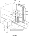
- FIG. 1 shows a specimen testing apparatus 100 capable of automatically processing multiple ones of the specimen containers 102 (e.g., blood collection tubes - see FIGs. 2 and 3 ).
- the specimen containers 102 may be contained in one or more racks 104 at a loading area 105 prior to transportation to, and analysis by, one or more analyzers (e.g., first, second, and third analyzer 106, 108, 110, respectively) arranged about the specimen testing apparatus 100. It should be apparent that more or less numbers of analyzers can be used.
- the analyzers may be any combination of clinical chemistry analyzers and/or assaying instruments, or the like.
- the specimen containers 102 may be any transparent or translucent container, such as a blood collection tube, test tube, or other clear glass or plastic container configured to contain a specimen 212.
- multiple labels 218 may be adhered and may slightly overlap each other. Accordingly, although the label 218 may occlude a view of some portion of the specimen 212, some portion of the specimen 212 may still be viewable from at least one lateral viewpoint.
- the specimen 212 may include a serum or plasma portion 212SP and a settled blood portion 212SB contained within the tube 215.
- Air 216 may be provided above the serum and plasma portion 212SP and a line of demarcation between the air 216 and the serum and plasma portion 212SP is defined herein as a liquid-air interface LA.
- a line of demarcation between the serum or plasma portion 212SP and the settled blood portion 212SB is defined herein as a serum-blood interface SB.
- An interface between the air 216 and the cap 214 is referred to herein as a tube-cap interface TC.
- a height of the serum or plasma portion 212SP is HSP and is defined as a height from the top of the serum or plasma portion 212SP to a top of the settled blood portion 212SB, i.e., from LA to SB.
- a height of the settled blood portion 212SB is HSB and is defined as a height from a bottom of the settled blood portion 212SB to the top of the settled blood portion 212SB at SB.
- a height of the serum or plasma portion 212SP is HSP and is defined as the height from the top of the serum or plasma portion 212SP at LA to a top of the gel separator 313 at SG.
- the height of the settled blood portion 212SB is HSB and is defined as the height from the bottom of the settled blood portion 212SB to a bottom of the gel separator 313 at BG.
- a height of the tube HT is defined herein as the height from the bottom-most part of the tube 215 to a bottom of the cap 214.
- Carriers 122 may be passive, non-motored pucks that may be configured to carry a single specimen container 102 on the track 121, where the track 121 is moveable.
- carrier 122 may be automated including an onboard drive motor, such as a linear motor that is programmed to move about the track 121 and stop at pre-programmed locations, where the track 121 is stationary.
- the carriers 122 may each include a holder 122H ( FIG. 4A ) configured to hold and support the specimen container 102 in a defined, upright orientation.
- the holder 122H may include a plurality of fingers, leaf springs, or combinations thereof that secure the specimen container 102 in the carrier 122, but where at least some are laterally moveable or flexible to accommodate for different sizes of specimen containers 102 to be received therein.
- a robot 124 may be provided at the loading area 105 and may be configured to grasp the specimen containers 102 from the one or more racks 104 and load the specimen containers 102 onto the carriers 122, such as on an input lane or other location of the track 121.
- the robot 124 may include one or more (e.g., at least two) robot arms or components capable of X and Z, Y and Z, X, Y, and Z, r and theta, or r, theta, and Z motion.
- Robot 124 may be a gantry robot, an articulated arm robot, an R-theta robot, or other suitable robot type wherein the robot 124 may be equipped with robotic gripper fingers that may be sized to pick up and place the specimen containers 102.
- the specimens may be placed in the carrier 122 in a predefined rotational orientation such that the labels 218 are provided on a back side of the specimen container 102, away from the front side that will be imaged (as shown in FIG.s 4A , 4D , and 6 ) so that the label 218 will not occlude a direct view of the specimen.
- the specimen containers 102 carried by carriers 122 may progress to a centrifuge 125 (e.g., a device configured to carry out fractionation of the specimen 212).
- Carriers 122 carrying specimen containers102 may be diverted to the centrifuge 125 by inflow lane or a suitable robot (not shown).
- the specimen containers 102 may exit on outflow lane, or otherwise be moved by the robot, and continue on the track 121.
- the specimen container 102 in carrier 122 may next be transported to a characterization apparatus 130 to be further described herein.
- Characterization apparatus 130 is configured to characterize, through the use of hyperspectral imaging, the specimen 212 contained in the specimen container 102, and may also be adapted to characterize the specimen container 102. Quantification of the specimen 212 may include determination of HSP, HSB, or even HTOT, and may include determination of location of LA, SB and/or SG, and/or BG. The characterization apparatus 130 including hyperspectral imaging may also be configured for determining a presence of an interferent, such as one or more of hemolysis (H), icterus (I), and/or lipemia (L) contained in a specimen 212.
- H hemolysis
- I icterus
- L lipemia
- quantification of one or more physical attributes of the specimen container 102 may take place at the characterization apparatus 130 such as determining HT, TC, or even cap color or cap height.
- the specimen 212 may be forwarded to be analyzed in the one or more analyzers (e.g., first, second, and third analyzers 106, 108, and/or 110).
- the specimen testing apparatus 100 may include sensors 116 at one or more suitable locations around the track 121. Sensors 116 may be used to detect a location of specimen containers 102 along the track 121 by means of reading the identification information 218i (see FIGs. 2 and 3 ) placed on the specimen container 102, or like information (not shown) provided on each carrier 122 and communicating with computer 143. In some embodiments, a barcode or RFID chip may be provided on the carrier 122 to aid in the tracking operation, for example. Other means for tracking the location of the carriers 122 may be used, such as proximity sensors. All of the sensors 116 may interface with the computer 143 so that the location of each specimen container 102 may be known at all times.
- Specimen testing apparatus 100 may be controlled by the computer 143, which may be a microprocessor-based central processing unit (CPU), having a suitable memory and suitable conditioning electronics, drivers, and software for carrying out the various computations and for operating the various components.
- Computer 143 may be housed as part of, or separate from, the base 120. The computer 143 may operate to control movement of the carriers 122 to and from the loading area 105, motion about the track 121, and motion to and from the centrifuge 125, motion to and from the characterization apparatus 130. Computer 143 may also control operation of the characterization apparatus 130. Computer 143 or a separate computer may control operation of the centrifuge 125, and motion to and from each analyzer 106, 108, and 110. In some embodiments, a separate integrated computer may control operation of each analyzer 106, 108, 110.
- CPU central processing unit
- the computer 143 may control the specimen testing apparatus 100 according to software, firmware, and/or hardware commands or circuits such as those used on the Dimension ® clinical chemistry analyzer sold by Siemens Healthcare Diagnostics Inc. of Tarrytown, New York, and such control is typical to those skilled in the art of computer-based electromechanical control programming and will not be further described herein.
- Other suitable systems for controlling the specimen testing apparatus 100 may be used.
- the control of the characterization apparatus 130 may also be provided by the computer 143, but according to methods described herein.
- Embodiments may be implemented using a computer interface module (CIM) 145 that allows the user to readily access a variety of status and control display screens. These screens may describe some or all aspects of a plurality of interrelated automated devices used for preparation and analysis of specimens 212.
- the CIM 145 may be employed to provide information about the operational status of a plurality of interrelated automated devices, as well as information describing the location of any specimen 212 as well as a status of tests to be performed on, or being performed on, the specimen 212.
- the CIM 145 may thus be adapted to facilitate interactions between an operator and the specimen testing apparatus 100.
- the CIM 145 may include a display screen adapted to display a menu including icons, scroll bars, boxes, and buttons through which the operator may interface with the specimen testing apparatus 100.
- the menu may comprise a number of function buttons programmed to display functional aspects of the specimen testing apparatus 100.
- Pre-screening the specimen 212 and quantification as described herein may ensure that the specimen 212 can be stopped from progressing to the one or more analyzers 106, 108, and 110 if there is insufficient amount of serum or plasma portion 212SP available to carry out the ordered tests.
- the ability to accurately quantify the physical location of LA and SB or SG may minimize not only the possibility of aspirating air, but also minimize the possibility of aspirating either settled blood portion 212SB or gel separator 313 (if the gel separator 313 is present). Thus, clogging and contamination of the specimen aspirating pipette used to aspirate serum or plasma portion 212SP for the analyzers 106, 108, 110 or other station(s) may be avoided or minimized.
- Characterization apparatus 130 may be configured to automatically characterize and/or quantify the specimen 212 (e.g., the serum or plasma portion 212SP, the settled blood portion 212SB, or both) and/or may quantify geometrical features of the specimen container 102.
- the information obtained by the characterization apparatus 130 may also allow for identification of H, I, and/or L, and/or N of the specimen 212.
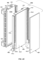
- Characterization apparatus 130 may include an imaging location 441 configured to receive a specimen container 102 containing a specimen 212, a light source 450 configured to provide lighting of the imaging location 441, and a hyperspectral image capture device 440 configured to generate and capture a spectrally-resolved image of a portion of the specimen container 102 and specimen 212 at the imaging location 441.
- the light arrays 456L, 456R may include clusters of R, G & B LEDs as lighting elements 460 that may be repeatedly arranged along the height of the light arrays 456L, 456R, such as in order RGB, RGB, RGB, etc..
- High power Oslon SSL model LEDs available from Osram Opto Semiconductors GmbH of Regensburg, Germany may be used, for example.
- Each of the different-colored LEDs may be illuminated at once.
- each or the R, G, and B LEDs as lighting elements 460 may be turned on simultaneously to provide multi- band illumination from the light source 450 to illuminate the specimen container 102 containing specimen 212 during imaging thereof.
- R, G, and B are only examples, and that other combinations of discrete light elements may be simultaneously illuminated, such as any combination of R, G, B, UV, white light, NIR (wavelength range of about 750nm to about 1,200nm), and/or mid IR (wavelength range of about 1,200nm to 2,000nm), and the like in the spectral range of 300nm to 2,000nm.
- the characterization apparatus 130 including hyperspectral imaging may include light source 450 as an active backdrop, as shown, i.e., that may be provided by the light panel assembly to provide back lighting. That is, the one or more light panel assemblies are located on a back side of the imaging location 441 opposite from the hyperspectral image capture device 440 and configured to provide back lighting of the specimen container 102 and specimen 212 at the imaging location 441.
- the light arrays 456L, 456R may be switchable, i.e., may be rapidly switched on and off to provide illumination of the imaging location 441.
- the switching of the lighting elements 460 may be accomplished by software operable on the computer 143 coupled with an appropriate power source and drivers. The switching of the lighting elements 460 may coincide with the image capture.
- the characterization apparatus 130 may include a housing 446 (shown dotted) that may at least partially surround or cover the track 121 and the imaging location 441.
- the housing 446 may be a box-like structure provided to minimize outside lighting variances.
- Housing 446 may include one or more doors (not shown) to allow the carriers 122 to enter into and/or exit from the housing 446.
- the ceiling may include an opening to allow a specimen container 102 to be loaded into a carrier 122 by a robot including a gripper adapted to grasp the specimen container 102.
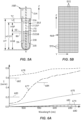
- the size of the slit aperture 462 may be chosen so that it is sized to provide a suitable image of the regions of the specimen container 102 and specimen 212 of interest.
- the width of the imaged region IR may be between about 1mm and 5 mm and may be located at an approximate center of the width of the specimen container 102. The dimension of the width region is less than the overall width of the specimen container 102. Other suitable widths may be used.
- the length L of the imaged region IR may encompass only the serum or plasma portion 212SP in some embodiments, but in other embodiments may include some or all of the cap 214, some or all of the region including air 216, serum or plasma portion 212SP, and the settled blood portion 212SB. In other embodiments, the length L of the imaged region IR may include only the serum or plasma portion 212SP and the settled blood portion 212SB.
- the location of the serum or plasma portion 212SP may be determined by any suitable segmentation method.
- Hyperspectral image capture device 440 may further include a lens system including a second lens 463 and a third lens 465, each of which may be concave lenses, wherein the second lens 463 may be located on a first side and the third lens 465 may be located on a second side of a spectrally-resolving element 464.
- the lens system including second lens 463 and third lens 465 is configured and operable to project an image of the plane of the slit aperture 462 onto a spectral image capture device 468.
- the second lens 463 operates to focus the light passing through the slit aperture 462 onto the spectrally-resolving element 464
- the third lens 465 focuses the dispersed spectral image onto the spectral image capture device 468. Any suitable lens or lens system may be used to accomplish these functions.
- the focal length of the second lens 463 may be between about 5mm and 50 mm, for example.
- the focal length of the third lens 465 may be between about 5 mm and 50 mm, for example. Other focal lengths may be used.
- the spectral image capture device 468 communicates the captured image data of the spectrally-resolved image to the computer 143, which is configured and operable to process the data of the spectrally-resolved image received at the spectral image capture device 468 and determine at least one of: segmentation of the specimen and/or specimen container, and determination of a presence or absence of an interferent in the serum or plasma portion 212SP of the specimen 212 (e.g., a fractionated specimen).
- the imaging location 441 is a location in the housing 446 including an expected location of the specimen container 102.
- the specimen container 102 may be placed at or stopped at the imaging location 441, such as by stopping the carrier 122 on the track 121 or otherwise placing the specimen container at the imaging location 441 by a robot (or even manually), so that it is approximately located in a center of the image window of the hyperspectral image capture device 440.
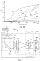
- the captured image data represents intensity I (norm) measured by the spectral image capture device 468 at each wavelength ⁇ , which then may be normalized to 1.0. This data provides intensity responses over the wavelength spectra of interest for the material that is located at that associated Z dimension.
- a similar data set may be generated for each respective vertical row of the image units 570.
- a plurality of subsets of data which may be in the form of a data matrix, may be obtained of intensity versus wavelength ⁇ for some or all of the image units 570.
- each subset of data may contain a spectral signature (e.g., data like in plot of FIG. 6A ) wherein each is indicative of a particular class of material associated with that vertical Z location.
- processing the data with computer 143 to identify the representative signature may, in one or more embodiments, be used to provide segmentation. Segmentation as defined herein is the use of the data of the spectrally-resolved image to determine the respective classes of material of at least the specimen 212, and possibly also the specimen container 102 along the vertical Z dimension.
- dual liquid thresholds could be used at 450 nm and 550 nm, for example.
- a determination of normality N can be made for the particular image unit 570 in the vertical Z direction if a maximum liquid threshold 683 was not exceeded at 450 nm, while also a minimum threshold 684 is exceeded at 550 nm.
- Suitable expert rules may be used, including examining the location of local extrema (minima and/or maxima) in the spectrum or one or more slopes of the spectral signature at one or more wavelengths or between wavelengths. Next expected is either gel separator 313 or settled blood portion 212SB. Again expert rules can be used to determine these classes, as well. For example, an abrupt change in signature can be expected going from serum or plasma portion 212SP to settled blood portion 212SB, because of the very low transmittance of the settled blood portion 212SB. Thus, one or more thresholds on either slope and/or Intensity I (norm) may be used.
- any of the characterization apparatus described herein may be used to determine an interferent, such as HIL, in the serum or plasma portion 212SP, following the segmentation process to determine the vertical location of the serum or plasma portion 212SP of the specimen 212.
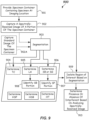
- FIG. 9 which represents a schematic diagram 900 of the functional components of the characterization apparatus 130, 730, 830A, 830B, in block 901, a specimen container 102 containing the specimen 212 (e.g., fractionated specimen) is provided at the imaging location 441.
- the specimen container 102 containing the specimen 212 may be supported in an upright orientation in the carrier 122 as shown in FIG. 4A , for example.
- the carrier 122 may be configured to travel on a track 121 of a specimen testing apparatus 100 as shown in FIGs. 1 .
- the segmentation in segmentation block 903 may determine, as an optional output, the tube-cap interface TC in block 904. This may be used to determine a height of the specimen container 102. Segmentation in segmentation block 903 may also determine as an output, the liquid-air interface LA in block 905, and may determine the serum-blood interface SB or the serum-gel interface SG in block 906. Once segmentation in segmentation block 903 is completed, the region of interest can be isolated in block 909, which may be to isolate any further analysis to only the serum or plasma portion 212SP, as the upper and lower boundaries thereof are now known.
- Some of the spectral signatures can be may be identified using expert rules, as described above, such as whether the specimen 212 is normal N. Likewise, the presence of lipemia L may be determined using expert rules. For example, for some levels of lipemia one or more thresholds based on Intensity I (norm) and/or slope(s) and/or local extrema (minima, maxima) at one or more wavelengths ⁇ may be used.
- the determination of H, I, and/or L in block 910 may be accomplished by analyzing the spectral signatures by means of a suitable machine learning method.
- the machine learning method may include a training phase where a sufficient number of annotated samples (e.g., hundreds or even thousands) of different configurations and levels of H, I, and L are evaluated in the characterization apparatus 130, 730, 830A, 830A and are provided to form the classifier.
- the annotation may involve graphically outlining various regions in a multitude of examples of specimen containers 102 having various specimen conditions, which is provided in a learning phase to form the classifier, along with the spectral information obtained from testing the example specimens.
- the classifier may be trained by annotating specimen conditions such as locations of air 216, areas occluded by label 218, locations of serum or plasma portion 212SP, locations of settled blood portion 212SB, locations of gel separator 313 (if included), and information about the type and level of interferent present, such as H, I, L and N.
- the number of levels of example specimens containing HIL may be provided in as many increments as is wanted from the classifier as an output.
- examples including different configurations of label 218 on the back side or even on the front side, different levels of serum or plasma portion 212SP, different levels of settled blood portion 212SB, different locations of gel separator 313, and different index levels of HIL may be provided as training inputs along with the spectral matrices for each containing the Intensity I (norm) versus wavelength information as a function of the Z dimension obtained by testing in the characterization apparatus 130, 730, 830A, 830B. Areas of the holder 122H may be ignored, as well as areas having barcode provided thereon.
- the machine learning analysis may include a neural network based approach wherein the data of the spectrally-resolved portion of the specimen container 102 comprising the serum or plasma portion 212SP determined by the previous segmentation in 903 may be provided as a data matrix input to the neural network to classify the type of interferent present, such as H, I, and/or L or if the specimen 212 is normal N.
- the neural network may also output an index (a level) associated with one or more of H, I, and/or L.
- the input to the neural network may comprise intensity or transmittance information as a function of wavelength ⁇ for each of the units 570 associated with the serum or plasma portion 212SP input as a data matrix for each specimen 212 tested.
- the image capture may be triggered and captured responsive to a triggering signal sent by computer 143 and provided in communication lines when the computer 143 receives a signal that the carrier 122 is located at the imaging location 441.
- a single image may be captured and that image is very informationally dense, including the spectral content information at each image unit 570.
- FIG. 10 illustrates a flowchart of a method of characterizing a specimen container 102 and/or a specimen 212.
- the method 1000 includes, in 1002, providing a specimen container (e.g., specimen container 102, such as a capped blood collection tube) containing a specimen (e.g., specimen 212) at an imaging location (e.g., imaging location 441).
- Imaging location 441 may be inside of a characterization apparatus 130, 730, 830A, 830B).
- the specimen container (e.g., specimen container 102) may be placed at the imaging location (e.g., imaging location 441) by being transported thereto on a track (e.g., track 121), by being placed there by a robot (e.g., robot 124 or the like), or manually.
- a track e.g., track 121
- robot e.g., robot 124 or the like
- the method 1000 includes, in 1004, providing a hyperspectral image capture device (e.g., hyperspectral image capture device 440, 740) that is configured to capture an image at the imaging location (e.g., imaging location 441).
- the method 1000 includes, in 1006, providing one or more light sources (e.g., light panel assemblies 450, 450A, 450B) configured to provide illumination of the imaging location 441.
- the illumination may be provided by back lighting as shown in FIG. 4A-4B or as front lighting as shown in FIG. 8A , or combinations thereof.
- the illumination may be provided as broadband illumination, and may include one or more subranges in the range of between about 300nm and 2,000nm.
- multiple sources may be used in combination (e.g., white light, NIR, and/or mid-IR).
- the illumination may be provided by a white light source (e.g., 400nm - 750nm).
- a white light source e.g., 400nm - 750nm.
- Other broadband spectral lighting ranges spanning at least 100 nm may be used.
- Further multi-band light sources may be used.
- the method 1000 includes, in 1010, capturing the spectrally-resolved image of a portion (e.g., the imaged region - IR) of the specimen container 102 and specimen 212 with the hyperspectral image capture device, and, in 1012, processing the spectrally-resolved image to determine at least one of: segmentation of the specimen and/or the specimen container, and a presence or absence of an interferent, such as HIL.
- the imaged region IR may be a small region having a width in the Y dimension that is a small fraction of the overall width of the specimen container 102.
- the length L of the imaged region IR may encompass at least the serum and plasma portion 212SP and at least some of the settled blood portion.
Landscapes
- Physics & Mathematics (AREA)
- Spectroscopy & Molecular Physics (AREA)
- General Physics & Mathematics (AREA)
- Health & Medical Sciences (AREA)
- General Health & Medical Sciences (AREA)
- Chemical & Material Sciences (AREA)
- Pathology (AREA)
- Biochemistry (AREA)
- Analytical Chemistry (AREA)
- Immunology (AREA)
- Life Sciences & Earth Sciences (AREA)
- Engineering & Computer Science (AREA)
- Nuclear Medicine, Radiotherapy & Molecular Imaging (AREA)
- Medical Informatics (AREA)
- Radiology & Medical Imaging (AREA)
- Quality & Reliability (AREA)
- Computer Vision & Pattern Recognition (AREA)
- Theoretical Computer Science (AREA)
- Hematology (AREA)
- Dispersion Chemistry (AREA)
- Investigating Or Analysing Materials By Optical Means (AREA)
- Automatic Analysis And Handling Materials Therefor (AREA)
Applications Claiming Priority (2)
| Application Number | Priority Date | Filing Date | Title |
|---|---|---|---|
| US201762534648P | 2017-07-19 | 2017-07-19 | |
| PCT/US2018/042344 WO2019018314A1 (en) | 2017-07-19 | 2018-07-16 | METHODS AND APPARATUS FOR SAMPLE CHARACTERIZATION USING HYPERSPECTRAL IMAGING |
Publications (3)
| Publication Number | Publication Date |
|---|---|
| EP3655757A1 EP3655757A1 (en) | 2020-05-27 |
| EP3655757A4 EP3655757A4 (en) | 2020-08-12 |
| EP3655757B1 true EP3655757B1 (en) | 2025-04-16 |
Family
ID=65015533
Family Applications (1)
| Application Number | Title | Priority Date | Filing Date |
|---|---|---|---|
| EP18835206.6A Active EP3655757B1 (en) | 2017-07-19 | 2018-07-16 | Apparatus and method for specimen characterization using hyperspectral imaging |
Country Status (5)
| Country | Link |
|---|---|
| US (1) | US11333553B2 (enExample) |
| EP (1) | EP3655757B1 (enExample) |
| JP (1) | JP7057820B2 (enExample) |
| CN (1) | CN110869740A (enExample) |
| WO (1) | WO2019018314A1 (enExample) |
Families Citing this family (5)
| Publication number | Priority date | Publication date | Assignee | Title |
|---|---|---|---|---|
| EP3357842B1 (en) * | 2017-02-03 | 2022-03-23 | Roche Diagnostics GmbH | Laboratory automation system |
| EP3882849A1 (en) | 2020-03-16 | 2021-09-22 | F. Hoffmann-La Roche AG | Method for determining characteristics of a sample vessel in an in-vitro diagnostics system, analyzing device, and in-vitro diagnostics system |
| JP7470587B2 (ja) * | 2020-07-14 | 2024-04-18 | 株式会社日立製作所 | 検体性状判別装置及び検体性状判別方法 |
| DE102022213200A1 (de) * | 2022-01-18 | 2023-07-20 | Robert Bosch Gesellschaft mit beschränkter Haftung | Verfahren zum transmissivitätsbewussten Chroma-Keying |
| WO2025137430A1 (en) * | 2023-12-20 | 2025-06-26 | Cytoviva, Inc. | Hyperspectral imaging for red blood cell membrane oxidative status |
Family Cites Families (54)
| Publication number | Priority date | Publication date | Assignee | Title |
|---|---|---|---|---|
| US20020001110A1 (en) | 1987-09-11 | 2002-01-03 | Michael H. Metz | Holographic light panels and flat panel display systems and method and apparatus for making same |
| JPH07280814A (ja) * | 1994-04-14 | 1995-10-27 | Hitachi Ltd | 検体検査自動化システム |
| US6353471B1 (en) | 1995-10-10 | 2002-03-05 | Cme Telemetrix Inc. | Method and apparatus for non-destructive screening of specimen integrity |
| JP3994143B2 (ja) * | 1995-11-21 | 2007-10-17 | エヌアイアール ダイアグナスティック インク. | 血液分析器のための検体の迅速な分光光度法の予備検査鑑別方法及び装置 |
| US6929953B1 (en) | 1998-03-07 | 2005-08-16 | Robert A. Levine | Apparatus for analyzing biologic fluids |
| US6388750B1 (en) | 1998-12-17 | 2002-05-14 | Beckman Coulter, Inc. | Device and method for preliminary testing a neat serum sample in a primary collection tube |
| US6522398B2 (en) | 1999-02-08 | 2003-02-18 | Cme Telemetrix Inc. | Apparatus for measuring hematocrit |
| US7180588B2 (en) | 1999-04-09 | 2007-02-20 | Plain Sight Systems, Inc. | Devices and method for spectral measurements |
| US6565802B1 (en) | 1999-06-03 | 2003-05-20 | Baxter International Inc. | Apparatus, systems and methods for processing and treating a biological fluid with light |
| EP1059522A1 (en) * | 1999-06-11 | 2000-12-13 | F. Hoffmann-La Roche Ag | Method and apparatus for examining fluids of biological origin |
| US6797518B1 (en) | 2000-09-11 | 2004-09-28 | Ortho-Clinical Diagnostics, Inc. | Analysis method with sample quality measurement |
| ATE492794T1 (de) | 2002-01-19 | 2011-01-15 | Pvt Probenverteiltechnik Gmbh | Verfahren und vorrichtung zur analyse von körperflüssigkeiten |
| US6831688B2 (en) * | 2002-04-08 | 2004-12-14 | Recon/Optical, Inc. | Multispectral or hyperspectral imaging system and method for tactical reconnaissance |
| CA2799683C (en) | 2003-07-02 | 2014-03-25 | Terumo Bct, Inc. | Monitoring and control system for blood processing |
| US8634607B2 (en) * | 2003-09-23 | 2014-01-21 | Cambridge Research & Instrumentation, Inc. | Spectral imaging of biological samples |
| US7652765B1 (en) * | 2004-03-06 | 2010-01-26 | Plain Sight Systems, Inc. | Hyper-spectral imaging methods and devices |
| WO2006040387A1 (en) | 2004-10-11 | 2006-04-20 | Thermo Fisher Scientific Oy | Method for automatically detecting factors that disturb analysis by a photometer |
| JP4875391B2 (ja) | 2006-03-30 | 2012-02-15 | シスメックス株式会社 | 検体分析装置 |
| JP4949898B2 (ja) | 2007-03-09 | 2012-06-13 | シスメックス株式会社 | 血球分析装置 |
| US8744775B2 (en) * | 2007-12-28 | 2014-06-03 | Weyerhaeuser Nr Company | Methods for classification of somatic embryos comprising hyperspectral line imaging |
| US7903241B2 (en) | 2008-03-21 | 2011-03-08 | Abbott Point Of Care, Inc. | Method and apparatus for determining red blood cell indices of a blood sample utilizing the intrinsic pigmentation of hemoglobin contained within the red blood cells |
| JP2012515931A (ja) | 2008-04-25 | 2012-07-12 | ウィンケルマン、ジェイムズ | 全血球数及び白血球百分率を決定するシステム及び方法 |
| EP2148205B1 (en) | 2008-07-25 | 2013-01-02 | F. Hoffmann-La Roche AG | A method and laboratory system for handling sample tubes and an image analysing unit |
| JP5465850B2 (ja) | 2008-08-01 | 2014-04-09 | シスメックス株式会社 | 試料分析システム |
| US20110144505A1 (en) * | 2008-08-20 | 2011-06-16 | Masaki Yamamoto | Optical device and method for shape and gradient detection and/or measurement and associated device |
| CN102341810B (zh) | 2009-01-06 | 2018-08-10 | 西门子医疗保健诊断公司 | 用于小瓶和容器上的帽体的存在和类型的自动化探测的方法和设备 |
| KR101306340B1 (ko) | 2009-01-08 | 2013-09-06 | 삼성전자주식회사 | 생화학 시료에 포함된 성분의 농도 측정 방법 및 이를 이용한 검사 결과의 신뢰도 추정 방법 |
| JP2010276552A (ja) | 2009-05-29 | 2010-12-09 | Toyota Motor Corp | スペクトル測定装置 |
| WO2011019576A1 (en) * | 2009-08-13 | 2011-02-17 | Siemens Healthcare Diagnostics Inc. | Methods and apparatus for ascertaining interferents and physical dimensions in liquid samples and containers to be analyzed by a clinical analyzer |
| US8381581B2 (en) | 2009-09-23 | 2013-02-26 | Brooks Automation, Inc. | Volumetric measurement |
| BR112012023287A2 (pt) | 2010-03-17 | 2017-03-21 | Zeng Haishan | aparelho e método para geração de imagem multiespectral, e, método para quantificação de informação fisiológica e morfológica de tecido |
| KR20130103548A (ko) * | 2010-11-05 | 2013-09-23 | 가부시키가이샤 엑사마스티카 | 촬영장치 및 해당 촬영장치에 의해서 촬영한 화상의 화상처리방법 및 화상촬영시스템 |
| EP2520923A1 (en) | 2011-05-06 | 2012-11-07 | bioMérieux | Bio-imaging method and system |
| US8704262B2 (en) * | 2011-08-11 | 2014-04-22 | Goldeneye, Inc. | Solid state light sources with common luminescent and heat dissipating surfaces |
| JP5474903B2 (ja) | 2011-09-28 | 2014-04-16 | あおい精機株式会社 | 検査前処理装置、検査前処理方法、及び検体処理装置 |
| US20150044098A1 (en) | 2012-01-30 | 2015-02-12 | Scanadu Incorporated | Hyperspectral imaging systems, units, and methods |
| EP2950708B1 (en) * | 2013-01-30 | 2019-01-16 | Koninklijke Philips N.V. | Imaging system with hyperspectral camera guided probe |
| US9619883B2 (en) * | 2013-03-15 | 2017-04-11 | Hypermed Imaging, Inc. | Systems and methods for evaluating hyperspectral imaging data using a two layer media model of human tissue |
| EP2910926A1 (de) * | 2014-02-19 | 2015-08-26 | F.Hoffmann-La Roche Ag | Verfahren und Vorrichtung zum Zuordnen einer Blutplasmaprobe |
| JP5793219B1 (ja) * | 2014-05-19 | 2015-10-14 | 佐鳥 新 | 撮像装置及び撮像方法 |
| CN104330362B (zh) * | 2014-10-16 | 2017-02-01 | 中国科学院上海技术物理研究所 | 一种非接触式基于超连续衰荡光谱的全血分类系统及方法 |
| US11009467B2 (en) | 2015-02-17 | 2021-05-18 | Siemens Healthcare Diagnostics Inc. | Model-based methods and apparatus for classifying an interferent in specimens |
| CN105223732B (zh) * | 2015-10-23 | 2018-03-16 | 京东方光科技有限公司 | 背光源及显示装置 |
| JP2017110931A (ja) * | 2015-12-14 | 2017-06-22 | 住友電気工業株式会社 | 分光撮像装置及びその組立方法 |
| JP7030056B2 (ja) | 2016-01-28 | 2022-03-04 | シーメンス・ヘルスケア・ダイアグノスティックス・インコーポレーテッド | 試料容器と試料の特徴付けのための方法及び装置 |
| EP3408653B1 (en) | 2016-01-28 | 2024-01-17 | Siemens Healthcare Diagnostics Inc. | Methods and apparatus adapted to quantify a specimen from multiple lateral views |
| CN108770364A (zh) | 2016-01-28 | 2018-11-06 | 西门子医疗保健诊断公司 | 用于使用多个曝光来对样品容器和/或样品进行成像的方法和装置 |
| WO2017132168A1 (en) | 2016-01-28 | 2017-08-03 | Siemens Healthcare Diagnostics Inc. | Methods and apparatus for multi-view characterization |
| WO2017132169A1 (en) | 2016-01-28 | 2017-08-03 | Siemens Healthcare Diagnostics Inc. | Methods and apparatus for detecting an interferent in a specimen |
| EP3408652B1 (en) | 2016-01-28 | 2020-12-16 | Siemens Healthcare Diagnostics Inc. | Methods and apparatus for classifying an artifact in a specimen |
| WO2017132167A1 (en) | 2016-01-28 | 2017-08-03 | Siemens Healthcare Diagnostics Inc. | Methods and apparatus adapted to identify a specimen container from multiple lateral views |
| US11073472B2 (en) | 2016-11-14 | 2021-07-27 | Siemens Healthcare Diagnostics Inc. | Methods and apparatus for characterizing a specimen using pattern illumination |
| EP3610270B1 (en) | 2017-04-13 | 2024-05-29 | Siemens Healthcare Diagnostics Inc. | Methods and apparatus for label compensation during specimen characterization |
| EP3655758B1 (en) | 2017-07-19 | 2024-05-15 | Siemens Healthcare Diagnostics, Inc. | Stray light compensating methods and apparatus for characterizing a specimen |
-
2018
- 2018-07-16 US US16/632,323 patent/US11333553B2/en active Active
- 2018-07-16 EP EP18835206.6A patent/EP3655757B1/en active Active
- 2018-07-16 WO PCT/US2018/042344 patent/WO2019018314A1/en not_active Ceased
- 2018-07-16 JP JP2020502195A patent/JP7057820B2/ja active Active
- 2018-07-16 CN CN201880047784.XA patent/CN110869740A/zh active Pending
Also Published As
| Publication number | Publication date |
|---|---|
| EP3655757A4 (en) | 2020-08-12 |
| CN110869740A (zh) | 2020-03-06 |
| JP2020527713A (ja) | 2020-09-10 |
| US20200166405A1 (en) | 2020-05-28 |
| WO2019018314A1 (en) | 2019-01-24 |
| US11333553B2 (en) | 2022-05-17 |
| EP3655757A1 (en) | 2020-05-27 |
| JP7057820B2 (ja) | 2022-04-20 |
Similar Documents
| Publication | Publication Date | Title |
|---|---|---|
| CN108474733B (zh) | 用于表征样品容器和样品的方法和装置 | |
| EP3408648B1 (en) | Methods and apparatus for imaging a specimen container and/or specimen using multiple exposures | |
| EP3655757B1 (en) | Apparatus and method for specimen characterization using hyperspectral imaging | |
| EP3655758B1 (en) | Stray light compensating methods and apparatus for characterizing a specimen | |
| EP3538870B1 (en) | Methods and apparatus for characterizing a specimen using pattern illumination | |
| CN111556961A (zh) | 用于使用具有经缩减的训练的神经网络的生物流体试样表征的方法和装置 | |
| US12253533B2 (en) | Methods and apparatus providing calibration of background illumination for sample and/or sample container characterization | |
| HK40017070A (en) | Methods and apparatus for specimen characterization using hyperspectral imaging | |
| CN114585887B (zh) | 针对样本容器表征提供前景照明校准的方法和设备 | |
| HK1253667B (en) | Methods and apparatus for characterizing a specimen container and specimen | |
| HK40017834A (en) | Stray light compensating methods and apparatus for characterizing a specimen | |
| HK40007198A (en) | Methods and apparatus for characterizing a specimen using pattern illumination | |
| HK40007198B (en) | Methods and apparatus for characterizing a specimen using pattern illumination |
Legal Events
| Date | Code | Title | Description |
|---|---|---|---|
| STAA | Information on the status of an ep patent application or granted ep patent |
Free format text: STATUS: THE INTERNATIONAL PUBLICATION HAS BEEN MADE |
|
| PUAI | Public reference made under article 153(3) epc to a published international application that has entered the european phase |
Free format text: ORIGINAL CODE: 0009012 |
|
| STAA | Information on the status of an ep patent application or granted ep patent |
Free format text: STATUS: REQUEST FOR EXAMINATION WAS MADE |
|
| 17P | Request for examination filed |
Effective date: 20200212 |
|
| AK | Designated contracting states |
Kind code of ref document: A1 Designated state(s): AL AT BE BG CH CY CZ DE DK EE ES FI FR GB GR HR HU IE IS IT LI LT LU LV MC MK MT NL NO PL PT RO RS SE SI SK SM TR |
|
| AX | Request for extension of the european patent |
Extension state: BA ME |
|
| A4 | Supplementary search report drawn up and despatched |
Effective date: 20200710 |
|
| RIC1 | Information provided on ipc code assigned before grant |
Ipc: G01N 21/31 20060101ALI20200706BHEP Ipc: G01N 15/05 20060101ALI20200706BHEP Ipc: G01J 3/28 20060101AFI20200706BHEP Ipc: G01N 35/00 20060101ALI20200706BHEP Ipc: G01N 35/04 20060101ALI20200706BHEP |
|
| DAV | Request for validation of the european patent (deleted) | ||
| DAX | Request for extension of the european patent (deleted) | ||
| STAA | Information on the status of an ep patent application or granted ep patent |
Free format text: STATUS: EXAMINATION IS IN PROGRESS |
|
| 17Q | First examination report despatched |
Effective date: 20220407 |
|
| REG | Reference to a national code |
Ref country code: DE Ref legal event code: R079 Free format text: PREVIOUS MAIN CLASS: G01N0021010000 Ipc: G01N0021310000 Ref country code: DE Ref legal event code: R079 Ref document number: 602018081176 Country of ref document: DE Free format text: PREVIOUS MAIN CLASS: G01N0021010000 Ipc: G01N0021310000 |
|
| GRAP | Despatch of communication of intention to grant a patent |
Free format text: ORIGINAL CODE: EPIDOSNIGR1 |
|
| STAA | Information on the status of an ep patent application or granted ep patent |
Free format text: STATUS: GRANT OF PATENT IS INTENDED |
|
| RIC1 | Information provided on ipc code assigned before grant |
Ipc: G01J 3/28 20060101ALI20241104BHEP Ipc: G01J 3/02 20060101ALI20241104BHEP Ipc: G01N 35/04 20060101ALI20241104BHEP Ipc: G01N 35/00 20060101ALI20241104BHEP Ipc: G01N 15/05 20060101ALI20241104BHEP Ipc: G01N 21/31 20060101AFI20241104BHEP |
|
| INTG | Intention to grant announced |
Effective date: 20241114 |
|
| GRAS | Grant fee paid |
Free format text: ORIGINAL CODE: EPIDOSNIGR3 |
|
| GRAA | (expected) grant |
Free format text: ORIGINAL CODE: 0009210 |
|
| STAA | Information on the status of an ep patent application or granted ep patent |
Free format text: STATUS: THE PATENT HAS BEEN GRANTED |
|
| AK | Designated contracting states |
Kind code of ref document: B1 Designated state(s): AL AT BE BG CH CY CZ DE DK EE ES FI FR GB GR HR HU IE IS IT LI LT LU LV MC MK MT NL NO PL PT RO RS SE SI SK SM TR |
|
| REG | Reference to a national code |
Ref country code: GB Ref legal event code: FG4D |
|
| P01 | Opt-out of the competence of the unified patent court (upc) registered |
Free format text: CASE NUMBER: APP_13319/2025 Effective date: 20250318 |
|
| REG | Reference to a national code |
Ref country code: CH Ref legal event code: EP Ref country code: DE Ref legal event code: R096 Ref document number: 602018081176 Country of ref document: DE |
|
| REG | Reference to a national code |
Ref country code: IE Ref legal event code: FG4D |
|
| REG | Reference to a national code |
Ref country code: NL Ref legal event code: MP Effective date: 20250416 |
|
| PG25 | Lapsed in a contracting state [announced via postgrant information from national office to epo] |
Ref country code: NL Free format text: LAPSE BECAUSE OF FAILURE TO SUBMIT A TRANSLATION OF THE DESCRIPTION OR TO PAY THE FEE WITHIN THE PRESCRIBED TIME-LIMIT Effective date: 20250416 |
|
| REG | Reference to a national code |
Ref country code: AT Ref legal event code: MK05 Ref document number: 1786000 Country of ref document: AT Kind code of ref document: T Effective date: 20250416 |
|
| PG25 | Lapsed in a contracting state [announced via postgrant information from national office to epo] |
Ref country code: PT Free format text: LAPSE BECAUSE OF FAILURE TO SUBMIT A TRANSLATION OF THE DESCRIPTION OR TO PAY THE FEE WITHIN THE PRESCRIBED TIME-LIMIT Effective date: 20250818 Ref country code: ES Free format text: LAPSE BECAUSE OF FAILURE TO SUBMIT A TRANSLATION OF THE DESCRIPTION OR TO PAY THE FEE WITHIN THE PRESCRIBED TIME-LIMIT Effective date: 20250416 Ref country code: FI Free format text: LAPSE BECAUSE OF FAILURE TO SUBMIT A TRANSLATION OF THE DESCRIPTION OR TO PAY THE FEE WITHIN THE PRESCRIBED TIME-LIMIT Effective date: 20250416 |
|
| PGFP | Annual fee paid to national office [announced via postgrant information from national office to epo] |
Ref country code: DE Payment date: 20250919 Year of fee payment: 8 |
|
| REG | Reference to a national code |
Ref country code: LT Ref legal event code: MG9D |
|
| PG25 | Lapsed in a contracting state [announced via postgrant information from national office to epo] |
Ref country code: NO Free format text: LAPSE BECAUSE OF FAILURE TO SUBMIT A TRANSLATION OF THE DESCRIPTION OR TO PAY THE FEE WITHIN THE PRESCRIBED TIME-LIMIT Effective date: 20250716 Ref country code: GR Free format text: LAPSE BECAUSE OF FAILURE TO SUBMIT A TRANSLATION OF THE DESCRIPTION OR TO PAY THE FEE WITHIN THE PRESCRIBED TIME-LIMIT Effective date: 20250717 |
|
| PG25 | Lapsed in a contracting state [announced via postgrant information from national office to epo] |
Ref country code: PL Free format text: LAPSE BECAUSE OF FAILURE TO SUBMIT A TRANSLATION OF THE DESCRIPTION OR TO PAY THE FEE WITHIN THE PRESCRIBED TIME-LIMIT Effective date: 20250416 |
|
| PG25 | Lapsed in a contracting state [announced via postgrant information from national office to epo] |
Ref country code: BG Free format text: LAPSE BECAUSE OF FAILURE TO SUBMIT A TRANSLATION OF THE DESCRIPTION OR TO PAY THE FEE WITHIN THE PRESCRIBED TIME-LIMIT Effective date: 20250416 |
|
| PGFP | Annual fee paid to national office [announced via postgrant information from national office to epo] |
Ref country code: GB Payment date: 20250811 Year of fee payment: 8 |
|
| PG25 | Lapsed in a contracting state [announced via postgrant information from national office to epo] |
Ref country code: HR Free format text: LAPSE BECAUSE OF FAILURE TO SUBMIT A TRANSLATION OF THE DESCRIPTION OR TO PAY THE FEE WITHIN THE PRESCRIBED TIME-LIMIT Effective date: 20250416 |
|
| PG25 | Lapsed in a contracting state [announced via postgrant information from national office to epo] |
Ref country code: AT Free format text: LAPSE BECAUSE OF FAILURE TO SUBMIT A TRANSLATION OF THE DESCRIPTION OR TO PAY THE FEE WITHIN THE PRESCRIBED TIME-LIMIT Effective date: 20250416 |
|
| PG25 | Lapsed in a contracting state [announced via postgrant information from national office to epo] |
Ref country code: RS Free format text: LAPSE BECAUSE OF FAILURE TO SUBMIT A TRANSLATION OF THE DESCRIPTION OR TO PAY THE FEE WITHIN THE PRESCRIBED TIME-LIMIT Effective date: 20250716 |
|
| PG25 | Lapsed in a contracting state [announced via postgrant information from national office to epo] |
Ref country code: IS Free format text: LAPSE BECAUSE OF FAILURE TO SUBMIT A TRANSLATION OF THE DESCRIPTION OR TO PAY THE FEE WITHIN THE PRESCRIBED TIME-LIMIT Effective date: 20250816 |
|
| PG25 | Lapsed in a contracting state [announced via postgrant information from national office to epo] |
Ref country code: LV Free format text: LAPSE BECAUSE OF FAILURE TO SUBMIT A TRANSLATION OF THE DESCRIPTION OR TO PAY THE FEE WITHIN THE PRESCRIBED TIME-LIMIT Effective date: 20250416 |