EP3650737B1 - Connection structure for fluid device - Google Patents
Connection structure for fluid device Download PDFInfo
- Publication number
- EP3650737B1 EP3650737B1 EP18828286.7A EP18828286A EP3650737B1 EP 3650737 B1 EP3650737 B1 EP 3650737B1 EP 18828286 A EP18828286 A EP 18828286A EP 3650737 B1 EP3650737 B1 EP 3650737B1
- Authority
- EP
- European Patent Office
- Prior art keywords
- port
- annular member
- connector
- fluid
- protrusion
- Prior art date
- Legal status (The legal status is an assumption and is not a legal conclusion. Google has not performed a legal analysis and makes no representation as to the accuracy of the status listed.)
- Active
Links
Images


Classifications
-
- F—MECHANICAL ENGINEERING; LIGHTING; HEATING; WEAPONS; BLASTING
- F16—ENGINEERING ELEMENTS AND UNITS; GENERAL MEASURES FOR PRODUCING AND MAINTAINING EFFECTIVE FUNCTIONING OF MACHINES OR INSTALLATIONS; THERMAL INSULATION IN GENERAL
- F16L—PIPES; JOINTS OR FITTINGS FOR PIPES; SUPPORTS FOR PIPES, CABLES OR PROTECTIVE TUBING; MEANS FOR THERMAL INSULATION IN GENERAL
- F16L25/00—Construction or details of pipe joints not provided for in, or of interest apart from, groups F16L13/00 - F16L23/00
- F16L25/12—Joints for pipes being spaced apart axially
-
- F—MECHANICAL ENGINEERING; LIGHTING; HEATING; WEAPONS; BLASTING
- F16—ENGINEERING ELEMENTS AND UNITS; GENERAL MEASURES FOR PRODUCING AND MAINTAINING EFFECTIVE FUNCTIONING OF MACHINES OR INSTALLATIONS; THERMAL INSULATION IN GENERAL
- F16L—PIPES; JOINTS OR FITTINGS FOR PIPES; SUPPORTS FOR PIPES, CABLES OR PROTECTIVE TUBING; MEANS FOR THERMAL INSULATION IN GENERAL
- F16L19/00—Joints in which sealing surfaces are pressed together by means of a member, e.g. a swivel nut, screwed on, or into, one of the joint parts
- F16L19/06—Joints in which sealing surfaces are pressed together by means of a member, e.g. a swivel nut, screwed on, or into, one of the joint parts in which radial clamping is obtained by wedging action on non-deformed pipe ends
- F16L19/065—Joints in which sealing surfaces are pressed together by means of a member, e.g. a swivel nut, screwed on, or into, one of the joint parts in which radial clamping is obtained by wedging action on non-deformed pipe ends the wedging action being effected by means of a ring
-
- F—MECHANICAL ENGINEERING; LIGHTING; HEATING; WEAPONS; BLASTING
- F16—ENGINEERING ELEMENTS AND UNITS; GENERAL MEASURES FOR PRODUCING AND MAINTAINING EFFECTIVE FUNCTIONING OF MACHINES OR INSTALLATIONS; THERMAL INSULATION IN GENERAL
- F16L—PIPES; JOINTS OR FITTINGS FOR PIPES; SUPPORTS FOR PIPES, CABLES OR PROTECTIVE TUBING; MEANS FOR THERMAL INSULATION IN GENERAL
- F16L23/00—Flanged joints
- F16L23/02—Flanged joints the flanges being connected by members tensioned axially
-
- F—MECHANICAL ENGINEERING; LIGHTING; HEATING; WEAPONS; BLASTING
- F16—ENGINEERING ELEMENTS AND UNITS; GENERAL MEASURES FOR PRODUCING AND MAINTAINING EFFECTIVE FUNCTIONING OF MACHINES OR INSTALLATIONS; THERMAL INSULATION IN GENERAL
- F16L—PIPES; JOINTS OR FITTINGS FOR PIPES; SUPPORTS FOR PIPES, CABLES OR PROTECTIVE TUBING; MEANS FOR THERMAL INSULATION IN GENERAL
- F16L23/00—Flanged joints
- F16L23/04—Flanged joints the flanges being connected by members tensioned in the radial plane
-
- F—MECHANICAL ENGINEERING; LIGHTING; HEATING; WEAPONS; BLASTING
- F16—ENGINEERING ELEMENTS AND UNITS; GENERAL MEASURES FOR PRODUCING AND MAINTAINING EFFECTIVE FUNCTIONING OF MACHINES OR INSTALLATIONS; THERMAL INSULATION IN GENERAL
- F16L—PIPES; JOINTS OR FITTINGS FOR PIPES; SUPPORTS FOR PIPES, CABLES OR PROTECTIVE TUBING; MEANS FOR THERMAL INSULATION IN GENERAL
- F16L37/00—Couplings of the quick-acting type
- F16L37/08—Couplings of the quick-acting type in which the connection between abutting or axially overlapping ends is maintained by locking members
- F16L37/084—Couplings of the quick-acting type in which the connection between abutting or axially overlapping ends is maintained by locking members combined with automatic locking
- F16L37/098—Couplings of the quick-acting type in which the connection between abutting or axially overlapping ends is maintained by locking members combined with automatic locking by means of flexible hooks
- F16L37/0985—Couplings of the quick-acting type in which the connection between abutting or axially overlapping ends is maintained by locking members combined with automatic locking by means of flexible hooks the flexible hook extending radially inwardly from an outer part and engaging a bead, recess or the like on an inner part
-
- F—MECHANICAL ENGINEERING; LIGHTING; HEATING; WEAPONS; BLASTING
- F16—ENGINEERING ELEMENTS AND UNITS; GENERAL MEASURES FOR PRODUCING AND MAINTAINING EFFECTIVE FUNCTIONING OF MACHINES OR INSTALLATIONS; THERMAL INSULATION IN GENERAL
- F16L—PIPES; JOINTS OR FITTINGS FOR PIPES; SUPPORTS FOR PIPES, CABLES OR PROTECTIVE TUBING; MEANS FOR THERMAL INSULATION IN GENERAL
- F16L37/00—Couplings of the quick-acting type
- F16L37/08—Couplings of the quick-acting type in which the connection between abutting or axially overlapping ends is maintained by locking members
- F16L37/10—Couplings of the quick-acting type in which the connection between abutting or axially overlapping ends is maintained by locking members using a rotary external sleeve or ring on one part
- F16L37/113—Couplings of the quick-acting type in which the connection between abutting or axially overlapping ends is maintained by locking members using a rotary external sleeve or ring on one part the male part having lugs on its periphery penetrating into the corresponding slots provided in the female part
-
- F—MECHANICAL ENGINEERING; LIGHTING; HEATING; WEAPONS; BLASTING
- F16—ENGINEERING ELEMENTS AND UNITS; GENERAL MEASURES FOR PRODUCING AND MAINTAINING EFFECTIVE FUNCTIONING OF MACHINES OR INSTALLATIONS; THERMAL INSULATION IN GENERAL
- F16L—PIPES; JOINTS OR FITTINGS FOR PIPES; SUPPORTS FOR PIPES, CABLES OR PROTECTIVE TUBING; MEANS FOR THERMAL INSULATION IN GENERAL
- F16L37/00—Couplings of the quick-acting type
- F16L37/24—Couplings of the quick-acting type in which the connection is made by inserting one member axially into the other and rotating it to a limited extent, e.g. with bayonet-action
- F16L37/244—Couplings of the quick-acting type in which the connection is made by inserting one member axially into the other and rotating it to a limited extent, e.g. with bayonet-action the coupling being co-axial with the pipe
- F16L37/252—Couplings of the quick-acting type in which the connection is made by inserting one member axially into the other and rotating it to a limited extent, e.g. with bayonet-action the coupling being co-axial with the pipe the male part having lugs on its periphery penetrating into the corresponding slots provided in the female part
-
- F—MECHANICAL ENGINEERING; LIGHTING; HEATING; WEAPONS; BLASTING
- F16—ENGINEERING ELEMENTS AND UNITS; GENERAL MEASURES FOR PRODUCING AND MAINTAINING EFFECTIVE FUNCTIONING OF MACHINES OR INSTALLATIONS; THERMAL INSULATION IN GENERAL
- F16L—PIPES; JOINTS OR FITTINGS FOR PIPES; SUPPORTS FOR PIPES, CABLES OR PROTECTIVE TUBING; MEANS FOR THERMAL INSULATION IN GENERAL
- F16L47/00—Connecting arrangements or other fittings specially adapted to be made of plastics or to be used with pipes made of plastics
- F16L47/04—Connecting arrangements or other fittings specially adapted to be made of plastics or to be used with pipes made of plastics with a swivel nut or collar engaging the pipe
-
- F—MECHANICAL ENGINEERING; LIGHTING; HEATING; WEAPONS; BLASTING
- F16—ENGINEERING ELEMENTS AND UNITS; GENERAL MEASURES FOR PRODUCING AND MAINTAINING EFFECTIVE FUNCTIONING OF MACHINES OR INSTALLATIONS; THERMAL INSULATION IN GENERAL
- F16L—PIPES; JOINTS OR FITTINGS FOR PIPES; SUPPORTS FOR PIPES, CABLES OR PROTECTIVE TUBING; MEANS FOR THERMAL INSULATION IN GENERAL
- F16L47/00—Connecting arrangements or other fittings specially adapted to be made of plastics or to be used with pipes made of plastics
- F16L47/14—Flanged joints
-
- F—MECHANICAL ENGINEERING; LIGHTING; HEATING; WEAPONS; BLASTING
- F16—ENGINEERING ELEMENTS AND UNITS; GENERAL MEASURES FOR PRODUCING AND MAINTAINING EFFECTIVE FUNCTIONING OF MACHINES OR INSTALLATIONS; THERMAL INSULATION IN GENERAL
- F16L—PIPES; JOINTS OR FITTINGS FOR PIPES; SUPPORTS FOR PIPES, CABLES OR PROTECTIVE TUBING; MEANS FOR THERMAL INSULATION IN GENERAL
- F16L37/00—Couplings of the quick-acting type
- F16L37/08—Couplings of the quick-acting type in which the connection between abutting or axially overlapping ends is maintained by locking members
- F16L37/10—Couplings of the quick-acting type in which the connection between abutting or axially overlapping ends is maintained by locking members using a rotary external sleeve or ring on one part
- F16L37/107—Bayonet-type couplings
Definitions
- the invention relates to fitting assemblies for fluid device.
- a first fluid device which is equipped with a first fitting
- a second fluid device which is equipped with a second fitting
- an additional member such as a tube connects the first fitting with the second fitting.
- EP 1 909 017 A1 relates to a connecting structure for an integration panel and a fluid device.
- WO 2016/167100 A1 relates to a gasket for a fluid coupling and a fluid coupling.
- DE 35 36 784 A1 relates to a pipe connection between two pipe ends that are to be connected to one another with a sealing system.
- US 4 619 470 A is directed to connection assemblies such as a flange connection assembly.
- CH 386 790 A relates to a connection for plastic pipes.
- US 2012/013119 A1 is directed to a sanitary coupling and seal-forming system.
- Patent Literature 1 Japanese Unexamined Patent Application Publication No. H10-54489 A
- Conventional fitting assemblies for fluid device each need a tube to connect the first fluid device with the second fluid device through the first and second fittings such that the first and second fluid devices allow fluid to flow between each other.
- first and second fittings each need an inner ring and a union nut of relatively large axial size to couple a longitudinal end of the tube with the first or second fitting.
- connection between the first and second fluid devices requires space for the tube and the inner rings and union nuts between the first and second fittings. This prevents reduction in space for installation of the first and second fluid devices.
- An object of the invention is to provide a fitting assembly that can reduce space for installation of fluid devices.
- the invention is defined by the appended independent claim.
- Advantageous features are defined in the dependent claim.
- the invention is a fitting assembly for fluid device connecting a first fluid device with a second fluid device.
- the fitting assembly includes a first port, a second port, a first annular member, a second annular member, and a connector.
- the first port is annular, installed at the first fluid device, and connected with a first fluid channel of the first fluid device.
- the second port is annular, installed at the second fluid device, and connected with a second fluid channel of the second fluid device.
- the first annular member is installed at the first port and has a first coupler.
- the second annular member is installed at the second port and has a second coupler coupled with the first coupler to fix the second annular member to the first annular member.
- the connector is installed between the first port and the second port, seals a gap between the connector and the first port, and seals a gap between the connector and the second port.
- This fitting assembly can continue to fix the first and second annular members, while it can connect the first fluid device with the second fluid device to allow fluid to flow between the first and second fluid devices.
- the fitting assembly can prevent fluid leakage from the junction of the fluid devices.
- the fitting assembly needs no member such as a tube between the first and second fluid devices to connect the first fluid device with the second fluid device such that fluid can flow between the first and second fluid devices. Accordingly, the first fluid device is placed as close to the second fluid device as possible to reduce space for installation of the first and second fluid devices.
- the first annular member may include a first body and a first hook
- the second annular member may include a second body and a second hook or a hook rest.
- the first body is placed on an outer periphery of the first port and fixed to the first port.
- the first hook is installed at the first body, protrudes in an axial direction of the first annular member, and is bendable with respect to the first body.
- the second body is placed on an outer periphery of the second port and fixed to the second port.
- the second hook or the hook rest faces the first hook and is to be coupled with the first hook.
- the second hook or the hook rest is installed at the second body and protrudes in an axial direction of the second annular member.
- the first annular member and the second annular member may be inhibited from separating from each other when the first hook is coupled with the second hook or the hook rest.
- the first port may have the same shape as the second port, and the first annular member may have the same shape as the second annular member.
- the first port and the second port may be arranged coaxially and connected with each other only through the connector.
- the connector may include an extending portion between the first port and the second port.
- the second example is a fitting assembly for fluid device connecting a first fluid device with a second fluid device.
- the fitting assembly includes a first port, a second port, a first annular member, a second annular member, a connector, and a securing member.
- the first port is annular, installed at the first fluid device, and connected with a first fluid channel of the first fluid device.
- the second port is annular, installed at the second fluid device, and connected with a second fluid channel of the second fluid device.
- the first annular member is installed radially outside the first port.
- the second annular member is installed radially outside the second port.
- the connector is installed between the first port and the second port, seals a gap between the connector and the first port, and seals a gap between the connector and the second port.
- the securing member secures one of the first annular member and the second annular member to the other to bring the one closer to the other when the connector is installed between the first port and the second port.
- This fitting assembly uses the securing member to connect the first fluid device with the second fluid device to allow fluid to flow between the first and second fluid devices.
- the fitting assembly needs no member such as a tube between the first and second fluid devices to connect the first fluid device with the second fluid device such that fluid can flow between the first and second fluid devices. Accordingly, the first fluid device is placed as close to the second fluid device as possible to reduce space for installation of the first and second fluid devices.
- two sealing portions can prevent fluid leakage from the junction of the fluid devices.
- the first annular member and the second annular member may face each other.
- the first annular member may have a first tapered portion
- the second annular member may have a second tapered portion.
- the securing member may include a first slope and a second slope. The first slope is in contact with the first tapered portion in an axial direction of the first annular member. The second slope is in contact with the second tapered portion in an axial direction of the second annular member.
- the connector may include an extending portion between the first port and the second port.
- the first port may have the same shape as the second port.
- the third example is a fitting assembly for fluid device connecting a first fluid device with a second fluid device.
- the fitting assembly includes a first port, a second port, a first annular member, a second annular member, and a connector.
- the first port is annular, installed at the first fluid device, and connected with a first fluid channel of the first fluid device.
- the second port is annular, installed at the second fluid device, and connected with a second fluid channel of the second fluid device.
- the first annular member is installed at the first port and has a first thread on an outer periphery.
- the second annular member is installed at the second port and has a second thread on an inner periphery. The second thread can engage with the first thread to fix the second annular member to the first annular member.
- the connector is installed between the first port and the second port, seals a gap between the connector and the first port, and seals a gap between the connector and the second port.
- This fitting assembly can continue to fix the first and second annular members, while it can connect the first fluid device with the second fluid device to allow fluid to flow between the first and second fluid devices.
- the fitting assembly can prevent fluid leakage from the junction of the fluid devices.
- the fitting assembly needs no member such as a tube between the first and second fluid devices to connect the first fluid device with the second fluid device such that fluid can flow between the first and second fluid devices. Accordingly, the first fluid device is placed as close to the second fluid device as possible to reduce space for installation of the first and second fluid devices.
- the first annular member may radially face the second annular member.
- the first port may be fixed to the first annular member with a third thread
- the second port may be fixed to the second annular member with a fourth thread.
- the direction in which the first thread and the second thread wrap may be opposite to the direction in which the third thread and the fourth thread wrap.
- the connector may include an extending portion between the first port and the second port.
- the first port may have the same shape as the second port.
- the invention can reduce space for installation of the first and second fluid devices.
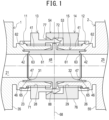
- FIG. 1 is a cross-sectional view of a fitting assembly for fluid device according to the first embodiment of the first example.
- FIG. 2 is a partially enlarged view of FIG. 1 .
- FIG. 3 is a diagram showing two fluid devices 1 and 2 of the fitting assembly of FIG. 1 separated from each other.
- FIG. 4 is a diagram showing the two fluid devices 1 and 2 of the fitting assembly of FIG. 1 during a process of connecting one of them with the other.
- the fitting assembly is used to connect the first fluid device 1 with the second fluid device 2 to allow fluid to flow between the devices 1 and 2 through the fitting assembly.
- the first and second fluid devices 1 and 2 have shapes to be aligned closely and in parallel. Examples of the first and second fluid devices 1 and 2 include, but are not limited to, valves, fluid meters, pumps, and fittings.
- the fitting assembly has a first port 11, a second port 12, a first annular member 13, a second annular member 14, and a connector 15.
- the first port 11 is installed at the first fluid device 1.
- the first port 11 is connected with a first fluid channel 21 in the first fluid device 1.
- the first port 11 has an annular shape.
- the second port 12 is installed at the second fluid device 2.
- the second port 12 is connected with a second fluid channel 25 in the second fluid device 2.
- the second port 12 has an annular shape.
- the first annular member 13 has a first coupler 53.
- the first annular member 13 is installed at the first port 11.
- the second annular member 14 has a second coupler 54, which can be coupled with the first coupler 53.
- the second annular member 14 is installed at the second port 12.
- the connector 15 is installed between the first port 11 and the second port 12.
- the connector 15 seals a gap between the connector 15 and the first port 11 and seals a gap between the connector 15 and the second port 12.
- the fitting assembly uses coupling of the second coupler 54 with the first coupler 53 to fix the second annular member 14 to the first annular member 13.
- the two fluid devices 1 and 2 are arranged to make their respective ports 11 and 12 axially face each other.
- the first port 11 is installed at the first fluid device 1 and integrated with the casing 35 of the first fluid device 1. Note that the first port 11 is not limited to be integrated with the casing 35, but it is separated from the casing 35.
- the first port 11 has an outer sleeve 41 and an inner sleeve 42.
- the outer sleeve 41 is an annular body of substantially constant inner diameters and installed around the opening of the first fluid channel 21 in the casing 35 to protrude to the outside of the casing 35.
- the outer sleeve 41 allows a portion of the connector 15 to enter the tip end (i.e. the first axial end) 43 of the outer sleeve 41.
- the outer sleeve 41 receives the portion of the connector 15, there is substantially no radial gap between the outer sleeve 41 and the portion of the connecter 15.
- the outer sleeve 41 includes a first thread 23, which extends on an outer periphery of the outer sleeve 41 in the axial direction of the outer sleeve 41.
- the first thread 23 is an external thread.
- the inner sleeve 42 is an annular body of substantially constant outer diameters smaller than the inner diameter of the outer sleeve 41.
- the inner sleeve 42 is installed around the opening of the first fluid channel 21 in the casing 35 to protrude in the same direction as the outer sleeve 41, i.e. in the first axial direction of the first port 11.
- the inner sleeve 42 is located inside the outer sleeve 41 to be separated by a radial distance from the outer sleeve 41 and to extend coaxially with the outer sleeve 41.
- the tip end 44 of the inner sleeve 42 is located nearer to the casing 35 than the tip end 43 of the outer sleeve 41.
- the inner sleeve 42 protrudes from the casing 35 to a distance shorter than the outer sleeve 41.
- the first port 11 has a twofold-annular structure on the second axial side (i.e. the side nearer to the casing 35) of the outer sleeve 41.
- the inner sleeve 42 has substantially the same inner diameter as the first fluid channel 21 and the connector 15. To make the first port 11 connect the first fluid device 1 with the connector 15 to allow fluid to flow between them, the inner sleeve 42 is placed between the first fluid device 1 and the connector 15 to connect the first fluid channel 21 with the internal space 48 of the connector 15.
- An annular groove 46 is provided between the outer periphery of the inner sleeve 42 and the inner periphery of the outer sleeve 41, which face each other.
- the groove 46 is open in the direction in which the outer and inner sleeves 41 and 42 protrude, i.e. to the second port 12.
- the groove 46 extends along the whole circumference of the outer and inner sleeve 41 and 42.
- a slope 47 is provided near the tip end 44 of the inner sleeve 42 to increase in diameter from the first fluid channel 21 toward the tip end 44 of the inner sleeve 42.
- the first port 11 is made of certain resin, for example, fluoropolymer such as tetrafluoroethylene-perfluoroalkylvinylether copolymer (perfluoroalkoxy alkane (PFA)), polyvinylidene fluoride (PVDF), ethylene-tetrafluoroethylene copolymer (ETFE), tetrafluoroethylene-hexafluoropropylene copolymer (fluorinated ethylene propylene (FEP)), or polytetrafluoroethylene (PTFE).
- fluoropolymer such as tetrafluoroethylene-perfluoroalkylvinylether copolymer (perfluoroalkoxy alkane (PFA)), polyvinylidene fluoride (PVDF), ethylene-tetrafluoroethylene copolymer (ETFE), tetrafluoroethylene-hexafluoropropylene copolymer (fluorinated ethylene
- the second port 12 has a reflected shape of the first port 11 with respect to a virtual center plane 68, and it is installed at the casing 55 of the second fluid device 2. Since the second port 12 has substantially the same shape as the first port 11, components of the second port 12 corresponding to ones of the first port 11 are marked with the same reference signs as the corresponding ones of the first port 11, and explanation on the components is omitted. For the explanatory convenience, substantially the same components can be marked with different reference signs, such as the first thread 23 and the second thread 26.
- the connector 15 has a first sealing portion 31 and a second sealing portion 32.
- the first sealing portion 31 seals a gap between the connector 15 and the first port 11.
- the second sealing portion 32 seals a gap between the connector 15 and the second port 12.
- the connector 15 has an annular shape.
- the connector 15 has a first portion 15a in contact with the first port 11 and a second portion 15b in contact with the second port 12. See FIG. 2 .
- the first portion 15a is an annular body of substantially constant inner diameters and has a fluid channel, which is a portion of the internal space 48 of the connector 15.
- the first portion 15a is mounted on the first port 11 such that it is placed on the outer sleeve 41 to connect its fluid channel with the first fluid channel 21.
- the first portion 15a includes a body 61, a first protrusion 62, and a second protrusion 63.
- the body 61 has a circular cylindrical shape, which is coupled with the whole inner periphery of the outer sleeve 41 to be surrounded by it when the first portion 15a is mounted on the first port 11.
- the first and second protrusions 62 and 63 are located at the first axial end (i.e. the end nearer to the first fluid device 1) of the body 61.
- the first and second protrusions 62 and 63 each have a circular ring shape.
- the first protrusion 62 is pressed into the whole circumference of the groove 46 of the first port 11 when the first portion 15a is mounted on the first port 11.
- the first protrusion 62 does not contact the inner face of the groove 46 nearest to the first fluid device 1.
- the second protrusion 63 has a tapered face 65, which reduces in inner diameter from the virtual center plane 68 toward the first fluid device 1.
- the tapered face 65 In a radial direction of the first portion 15a, the tapered face 65 is located inside the first protrusion 62. In an axial direction of the first portion 15a, the tapered face 65 faces the slope 47 of the inner sleeve 42. The tapered face 65 is pressed on the slope 47 when the first portion 15a is mounted on the first port 11.
- the connector 15 has a shape symmetric with respect to the virtual center plane 68, which is perpendicular to the axial direction of the connector 15 and located at the axial center of the connector 15.
- the second portion 15b has substantially the same shape of the first portion 15a. Accordingly, components of the second portion 15b corresponding to ones of the first components 15a are marked with the same reference signs as the corresponding ones of the first components 15a, and explanation on the components is omitted.
- the connector 15 is made of certain resin, for example, fluoropolymer such as PFA, PVDF, ETFE, FEP, or PTFE, or other thermoplastic resin.
- fluoropolymer such as PFA, PVDF, ETFE, FEP, or PTFE, or other thermoplastic resin.
- the connector 15 is a body integrated with the first and second portions 15a and 15b, which have substantially the same shape.
- the connector 15 may be an assembly of first and second portions, which differ in shape.
- the first annular member 13 surrounds the first port 11, especially its outer sleeve 41.
- the first annular member 13 has, in addition to the first coupler 53, a third thread 28 to be engaged with the first thread 23.
- the third thread 28 is provided on the inner periphery of the first annular member 13.
- the second annular member 14 surrounds the second port 12, especially its outer sleeve 41.
- the second annular member 14 has, in addition to the second coupler 54, a fourth thread 29 to be engaged with the second thread 26.
- the fourth thread 29 is provided on the inner periphery of the second annular member 14.
- the first annular member 13 has a first body 71 in addition to the first coupler 53.
- the first body 71 is placed on and fixed to the outer periphery of the first port 11.
- the first body 71 has an annular shape.
- the third thread 28 is provided on the inner periphery of the first body 71.
- the first body 71 is mounted on the first port 11 to surround the whole circumference of the outer sleeve 41 of the first port 11 when the third thread 28 is engaged with the first thread 23.
- the first body 71 extends in an axial direction of the first annular member 13.
- the first body 71 is located at the second axial side (i.e. the side nearer to the first fluid device 1) of the first annular member 13.
- the first coupler 53 has a first hook 72, which protrudes in an axial direction of the first annular member 13 and is bendable in a radial direction of the first body 71.
- the first hook 72 of the first coupler 53 is located at the first axial side of the first annular member 13, i.e. at the opposite side of the first annular member 13 with respect to the first fluid device 1.
- the first hook 72 protrudes from the end of the first body 71 to the first axial direction of the first annular member 13, i.e. toward the second fluid device 2.
- the tip end of the first hook 72 has a first corner 73.
- the number of the first hook 72 is at least one.
- the first hook 72 has a partial ring shape such as C, which is arranged coaxially with the first body 71. Accordingly, the first hook 72 is flexible.
- the first hooks 72 are arranged along the circumference of the first body 71 at certain intervals.
- the first hook 72 includes a tapered portion 74, which reduces in diameter from its side nearer to the casing 35 of the first fluid device 1 in the first axial direction of the first annular member 13, i.e. toward the second fluid device 2.
- the first hook 72 is flexible to transiently bend toward the radial inside of the first annular member 13, when receiving external force stronger than a certain level.
- the second annular member 14 has a second body 76 in addition to the second coupler 54.
- the second body 76 is placed on and fixed to the outer periphery of the second port 12.
- the second body 76 has an annular shape, whose inner periphery has a fourth thread 29.
- the second body 76 is mounted on the second port 12 to surround the whole circumference of the outer sleeve 41 of the second port 12 when the fourth thread 29 is engaged with the second thread 26.
- the second body 76 extends in an axial direction of the second annular member 14 and is located at the second axial side (i.e. the side nearer to the second fluid device 2) of the second annular member 14.
- the second coupler 54 has a second hook 77 to be engaged with the first hook 71.
- the second hook 77 protrudes in an axial direction of the second annular member 14.
- the second hook 77 of the second coupler 54 is located at the second axial side of the second annular member 14, i.e. at the opposite side of the second annular member 14 with respect to the second fluid device 2.
- the second hook 77 protrudes from an end of the second body 76 to the second axial direction of the second annular member 14, i.e. toward the first fluid device 1.
- the tip end of the second hook 77 has a second corner 78.
- the number of the second hook 77 is at least one.
- the second hook 77 has a partial ring shape such as C, which is arranged coaxially with the second body 76. Accordingly, the first hook 72 is flexible.
- the second hooks 77 are arranged along the circumference of the second body 76 at certain intervals.
- the second hook 77 includes a tapered portion 79, which reduces in diameter from the second axial direction of the second annular member 14, i.e. from its side nearer to the second fluid device 2, to the first axial direction of the second annular member 14, i.e. toward the first fluid device 1.
- the second hook 77 surrounds the side of the first hook 72 nearer to the first fluid device 1.
- the second hook 77 has an inner diameter larger than the second body 76.
- the second coupler 54 may have a hook rest such as a dent to be engaged with the first hook 72.
- the second coupler 54 may have a shape to be engaged with the first body 71 of the first annular member 13.
- the first annular member 13 is coupled with the second annular member 14 when the first hook 72 faces the second hook 77.
- the first annular member 13 is placed coaxially with the second annular member 14.
- the first annular member 13 is located radially inside the second annular member 14 to make the first corner 73 axially face the second corner 78.
- first and second hooks 72 and 77 engaged with each other prevent the first and second annular members 13 and 14 from separating from each other.
- the first and second hooks 72 and 77 make the first and second corners 73 and 78 contact each other, and accordingly, the first and second corners 73 and 78 are engaged with each other in the common axial direction of the first and second annular members 13 and 14.
- the first and second annular members 13 and 14 press the first protrusions 62 of the connector 15 into the corresponding grooves 46 and press the tapered faces 65 of the second protrusions 63 of the connector 15 onto the corresponding slopes 47 of the tip ends 44 of the inner sleeves 42.
- the first annular member 13 is made of certain resin, for example, fluoropolymer such as PFA, PVDF, ETFE, FEP, or PTFE.
- the second annular member 14 is made of certain resin, for example, fluoropolymer such as PFA, PVDF, ETFE, FEP, or PTFE.
- the first fluid device 1 is connected with the second fluid device 2 as follows. First, as shown in FIG. 3 , the third thread 28 is engaged with the first thread 23 to releasably fix the first annular member 13 to the first port 11. The fourth thread 29 is engaged with the second thread 26 to releasably fix the second annular member 14 to the second port 12. Next, the connector 15 is placed inside one of the first and second ports 11 and 12. As shown in FIG. 4 , the first fluid device 1 faces the second fluid device 2 at a remove from the second fluid device 2, and the connector 15 approaches the other of the first and second ports 11 and 12.
- the first hook 72 of the first annular member 13 transiently bends toward the radial inside of the first annular member 13 to allow the first annular member 13 to be placed inside the second annular member 14. Then, the first hook 72 is engaged with the second hook 77. Thus, the first annular member 13 is fixed to the second annular member 14 to prevent the annular members 13 and 14 from being axially separated from each other.
- first and second ports 11 and 12 are prevented from moving away from each other. This maintains connection between the first and second fluid devices 1 and 2 to allow fluid to flow between the fluid devices 1 and 2, i.e. connection among the first fluid channel 21, the second fluid channel 25, and the internal space 48 of the connector 15.
- first hook 72 engages with the second hook 77 forms the first and second sealing portions 31 and 32.
- the engagement causes the connector 15 to press its first protrusions 62 into the corresponding grooves 46 and press the tapered faces 65 of its second protrusions 63 onto the corresponding slopes 47 of the tip ends 44 of the inner sleeves 42.
- the first and second sealing portions 31 and 32 each form a primary sealing area 81 where axial sealing force acts and a secondary sealing area 82 where radial sealing force acts.
- An operator uses his/her hands and/or a tool to place the first hook 72 of the first annular member 13 inside the second hook 77 of the second annular member 14.
- the fitting assembly according to the first embodiment of the first can prevent fluid leakage from the junction of the first and second fluid devices 1 and 2.
- connection between the first and second fluid devices 1 and 2 to allow fluid to flow therebetween does not need any member such as a tube between the first and second fluid devices 1 and 2. This can place the two fluid devices 1 and 2 as closely to each other as possible, and reduce space for installation of the fluid devices 1 and 2.
- the connector 15 includes an extending portion 88, which is located between the first port 11 and the second port 12 when the first fluid device 1 is connected with the second fluid device 2 to allow fluid to flow between them.
- the extending portion 88 is placed between the first and second ports 11 and 12, and it is separated from both the ports 11 and 12.
- the extending portion 88 extends toward the radial outside of the connector 15 and has a ring shape.
- the extending portion 88 has an outer diameter larger than each tip end 43 of the first and second ports 11 and 12.
- the extending portion 88 is located on the virtual center plane 68 of the connector 15, i.e. on an axial intermediate portion (the boundary between the first portion 15a and the second portion 15b) of the connector 15.
- the extending portion 88 is arranged in a gap between the tip ends 43 and 43 of the first and second ports 11 and 12 when the connector 15 is placed on the ports 11 and 12.
- the extending portion 88 axially faces the tip ends 43 and 43 of the first and second ports 11 and 12.
- the extending portion 88 facilitates release of the connector 15 from the first and second ports 11 and 12.
- FIGS. 5-8 Components of fitting assemblies substantially corresponding to ones of the fitting assembly according to the first embodiment are marked in FIGS. 5-8 with the same reference signs as the corresponding ones, and explanation on the components is omitted.
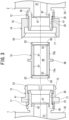
- FIG. 5 is a cross-sectional view of a fitting assembly according to the second embodiment of the first example. As shown in FIG. 5 , the fitting assembly differs from one according to the first embodiment in the following configuration: a first sealing portion 121 that seals a gap between the first port 111 and the connector 115; and a second sealing portion 122 that seals a gap between the second port 112 and the connector 115.
- the first port 111 is installed at the first fluid device 1 and integrated with the casing 35 of the first fluid device 1.
- the first port 111 has an annular body 125 and a protruding ring 126.
- the annular body 125 is a circular cylinder of substantially constant inner diameters, which is installed around the opening of the first fluid channel 21 in the casing 35 to protrude toward the outside of the casing 35.
- the annular body 125 allows a portion of the connector 115 to enter the tip end (i.e. the first axial end) of the annular body 125.
- the annular body 125 receives the portion of the connector 115, there is substantially no gap between the annular body 125 and the portion of the connector 115 except for the tip end of the annular body 125 and its vicinity.
- the first thread 23 extends in the axial direction of the annular body 125.
- the first thread 23 is an external thread.
- the protruding ring 126 is a ring-shaped body of an outer diameter smaller than the inner diameter of the annular body 125.
- the protruding ring 126 is installed around the opening of the first fluid channel 21 in the casing 35 to protrude in the same direction as the annular body 125, i.e. in the first axial direction of the annular body 125.
- the protruding ring 126 is placed inside the annular body 125 with separated by a radial distance from the annular body 125.
- the protruding ring 126 has substantially the same inner diameter as the first fluid channel 21 and the connector 115.
- the protruding ring 126 is located between the first fluid device 1 and the connector 115 and connects the first fluid channel 21 with the internal space 138 of the connector 115.
- the first port 111 connects the first fluid device 1 with the connector 115 to allow fluid to flow between them.
- the outer periphery of the protruding ring 126 includes a tapered face 128, which reduces in outer diameter to the direction in which the protruding ring 126 protrudes, i.e. to the first axial direction of the first port 111.
- the tapered face 128 extends along the whole circumference of the protruding ring 126.
- the tapered face 128 is separated by a distance from the inner periphery of the annular body 125.
- the second port 112 has substantially the same shape as the first port 111. Accordingly, components of the second port 112 corresponding to ones of the first port 111 are marked with the same reference signs as the corresponding ones of the first port 111, and explanation on the components is omitted. For the explanatory convenience, substantially the same components can be marked with different reference signs, such as the first thread 23 and the second thread 26.
- the connector 115 has a first portion 115a in contact with the first port 111 and a second portion 115b in contact with the second port 112.
- the first portion 115a is a circular cylinder of substantially constant inner diameters, whose internal space serves as a fluid channel.
- the first portion 115a is mounted on the first port 111 such that it is placed in the annular body 125 to connect its fluid channel with the first fluid channel 21.
- the first portion 115a includes a body 131 and a protrusion 132.
- the body 131 has a circular cylindrical shape, which is placed on the inner periphery of the annular body 125 when the first portion 115a is mounted on the first port 111. From the first axial end (i.e. the axial end nearer to the first fluid device 1) of the body 131, the protrusion 132 protrudes in the axial direction.
- the protrusion 132 has a circular ring shape, whose inner periphery has a slope 135.
- the protrusion 132 presses the slope 135 onto the tapered face 128 of the protruding ring 126.
- the slope 135 increases in diameter to the direction in which the protrusion 132 protrudes, i.e. toward the first fluid device 1.
- the slope 135 extends along the whole circumference of the protrusion 132.
- the connector 115 has a shape symmetric with respect to a virtual center plane 148, which is perpendicular to the axial direction of the connector 115 and located at the axial center of the connector 115.
- the first and second portions 115a and 115b have substantially the same shape.
- the above-described fitting assembly can reduce space for installation of the first and second fluid devices 1 and 2 connected with each other to allow fluid to flow between each other.
- the connector 115 forms the first sealing portion 121 and the second sealing portion 122; the connector 115 presses the slope 135 of the first portion 115a onto the tapered face 128 of the first port 111 and presses the slope 135 of the second portion 115b onto the tapered face 128 of the second port 112.
- FIG. 6 is a cross-sectional view of a fitting assembly according to the third embodiment of the first example. As shown in FIG. 6 , the fitting assembly differs from one according to the first embodiment in the following configuration: a first sealing portion 161 that seals a gap between the first port 151 and the connector 155; and a second sealing portion 162 that seals a gap between the second port 152 and the connector 155.
- the first port 151 is installed at the first fluid device 1 and integrated with the casing 35 of the first fluid device 1. On the outer periphery of the first port 151, the first thread 23 extends in the axial direction of the first port 151.
- the first thread 23 is an external thread.
- the first port 151 has an annular body 165 and a protrusion 166.
- the annular body 165 is a circular cylinder with a step on its inner periphery and protrudes away from the casing 35.
- the annular body 165 is located near the opening of the first fluid channel 21 in the casing 35.
- the annular body 165 has a first annular portion 165a on the first axial side of the step 167, i.e. near the opening of the first port 151.
- the first annular portion 165a allows a portion of the connector 155 to enter the first annular portion 165a.
- the first annular portion 165a closely contacts substantially the whole outer periphery of the portion of the connector 155.
- the annular body 165 has a second annular portion 165b on the second axial side of the step 167, i.e. near the first fluid device 1.
- the second annular portion 165b has substantially the same inner diameter as the first fluid channel 21 and the connector 115.
- the second annular portion 165b is placed between the first fluid device 1 and the connector 155 to connect the first fluid channel 21 with the internal space 178 of the connector 155 so that the first port 151 connects the first fluid device 1 with the connector 155 to allow fluid to flow between them.
- the protrusion 166 is a ring and protrudes from the first annular portion 165a to the first axial direction of the annular body 165.
- the inner periphery of the protrusion 166 has a slope 168, which increases in diameter from the annular body 165 toward the tip end of the protrusion 166, i.e. toward the opening of the first port 151.
- the slope 168 extends along the whole circumference of the protrusion 166.
- the second port 152 has a reflected shape of the first port 151 with respect to a virtual center plane 198, i.e. substantially the same shape as the first port 151.
- the connector 155 has a first portion 155a in contact with the first port 151 and a second portion 155b in contact with the second port 152.
- the first portion 155a is a circular cylinder of substantially constant inner diameters, whose internal space serves as a fluid channel.
- the first portion 155a is mounted on the first port 151 such that it is placed on the annular body 165, and thus, the first portion 155a connects its internal space 178, which serves as the fluid channel, with the first fluid channel 21.
- the first portion 155a includes a body 171 and a protrusion 172.
- the body 171 has a circular cylindrical shape.
- the protrusion 172 protrudes toward the radial outside of the connector 155.
- the protrusion 172 has a circular ring shape.
- the protrusion 172 presses its outer periphery, i.e. a tapered face 175, onto the slope 168 of the protrusion 166.
- the tapered face 175 increases in diameter from the annular body 165 to its axial outside.
- the tapered face 175 extends along the whole circumference of the protrusion 172.
- the connector 155 has a shape symmetric with respect to the virtual center plane 198, which is perpendicular to the axial direction of the connector 155 and located at the axial center of the connector 155.
- the first portion 155a and the second portion 155b have substantially the same shape.
- the connector 155 forms the first and second sealing portions 161 and 162; the connector 155 presses the tapered face 175 of the first portion 155a onto the slope 168 of the first port 151 and presses the tapered face 175 of the second portion 155b onto the slope 168 of the second port 152. This can prevent fluid leakage from the junction of the first and second fluid devices 1 and 2 and achieve short-distance connection between the first and second fluid devices 1 and 2 without any member such as a tube.
- the fitting assembly can reduce space for installation of the first and second fluid devices 1 and 2 connected with each other to allow fluid to flow between each other.
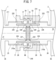
- FIG. 7 is a cross-sectional view of a fitting assembly according to the fourthembodiment of the first example. As shown in FIG. 7 , the fitting assembly differs from one according to the first embodiment in the following configuration: a first sealing portion 221 that seals a gap between the first port 211 and the connector 215; and a second sealing portion 222 that seals a gap between the second port 212 and the connector 215.
- the first port 211 is installed at the first fluid device 1 and integrated with the casing 35 of the first fluid device 1.
- the first port 211 has an outer sleeve 225 and an inner sleeve 226.
- the outer sleeve 225 is a circular cylinder of substantially constant inner diameters, which is installed near the first fluid channel 21 in the casing 35 to protrude toward the outside of the casing 35.
- the outer sleeve 225 allows a portion of the connector 215 to enter the tip end (i.e. the first axial end) of the outer sleeve 225.
- the outer sleeve 225 receives the portion of the connector 215, there is substantially no gap between the outer sleeve 225 and the portion of the connector 215.
- the first thread 23 extends in the axial direction of the outer sleeve 225.
- the first thread 23 is an external thread.
- the inner sleeve 226 is a circular cylinder of substantially constant outer diameters smaller than the inner diameter of the outer sleeve 225.
- the inner sleeve 226 protrudes in the same direction as the outer sleeve 225, i.e. in the first axial direction of the first port 211.
- the inner sleeve 226 is located near the first fluid channel 21 in the casing 35.
- the inner sleeve 226 is located inside the outer sleeve 225 and separated by a radial distance from the outer sleeve 225.
- the tip end of the inner sleeve 226 is located farther from the first or second fluid device 1 or 2 than the tip end of the outer sleeve 225, i.e. the inner sleeve 226 protrudes from the casing 35 to a distance longer than the outer sleeve 225.
- the first port 211 has a twofold-annular structure at the axially intermediate portion of the outer sleeve 225.
- the inner sleeve 226 has substantially the same inner diameter as the first fluid channel 21 and the connector 215.
- the inner sleeve 226 is located between the first fluid device 1 and the connector 215 to connect the first fluid channel 21 with the internal space of the connector 215.
- the first port 211 connects the first fluid device 1 with the connector 215 to allow fluid to flow between them.
- the tip end of the inner sleeve 226 is tapered toward the direction in which the inner sleeve 226 protrudes.
- the outer periphery of the tip end of the inner sleeve 226 has a tapered face 228, which reduces in diameter toward a virtual center plane 248, i.e. to the direction in which the inner sleeve 226 protrudes (or to the first axial direction of the first port 211).
- the tapered face 228 extends along the whole circumference of the tip end of the inner sleeve 226.
- the second port 212 has substantially the same shape as the first port 211.
- the connector 215 has a first portion 215a in contact with the first port 211 and a second portion 215b in contact with the second port 212.
- the first portion 215a is a circular cylinder, whose internal space serves as a fluid channel.
- the first portion 215a is mounted on the first port 211 such that the first portion 215a is coupled with the inner sleeve 226, and thus, the first portion 215a connects its fluid channel with the first fluid channel 21.
- the first portion 215a includes a body 231 and a protrusion 232.
- the body 231 has a circular cylindrical shape.
- the protrusion 232 protrudes to the radial inside of the connector 215.
- the protrusion 232 has a circular ring shape, whose inner periphery has a slope 235.
- the protrusion 232 presses the slope 235 onto the tapered face 228 of the inner sleeve 226.
- the slope 235 increases in diameter from the virtual center plane 248 toward the first or second fluid device 1 or 2.
- the slope 235 extends along the whole circumference of the protrusion 232.
- the connector 215 has a shape symmetric with respect to the virtual center plane 248, which is perpendicular to the axial direction of the connector 215 and located at the axial center of the connector 215.
- the first portion 215a and the second portion 215b have substantially the same shape.
- the connector 215 forms the first and second sealing portions 221 and 222; the connector 215 presses the slope 235 of the first portion 215a onto the tapered face 228 of the first port 211 and presses the slope 235 of the second portion 215b onto the tapered face 228 of the second port 212. This can prevent fluid leakage from the junction of the first and second fluid devices 1 and 2 and achieve short-distance connection between the first and second fluid devices 1 and 2 without any member such as a tube.
- the fitting assembly can reduce space for installation of the first and second fluid devices 1 and 2 connected with each other to allow fluid to flow between each other.
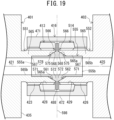
- FIG. 8 is a cross-sectional view of a fitting assembly according to the invention.
- FIG. 9 is a partial cross-sectional view of a first coupler 53 of a first annular member 263 and a second coupler 54 of a second annular member 264 of FIG. 8 from the first fluid device 1.
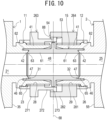
- FIG. 10 is a diagram showing the two fluid devices 1 and 2 of the fitting assembly of FIG. 8 during a process of connecting one of them with the other.
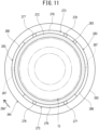
- FIG. 11 is a partial cross-sectional view of the first coupler 53 of the first annular member 263 and the second coupler of the second annular member 264 of FIG. 10 from the first fluid device 1.
- Components of the fitting assembly substantially corresponding to ones according to the first embodiment are marked in FIG. 11 with the same reference signs as the ones, and explanation on the components is omitted.
- the fitting assembly differs from one according to the first embodiment in the first annular member 263 and the second annular member 264.
- the first annular member 263 has a third body 271 in addition to the first coupler 53.
- the third body 271 has an annular shape, whose inner periphery has a third thread 28.
- the first coupler 53 has a first protrusion 272 and a concave wall 273.
- the first protrusion 272 protrudes from the third body 271 to the axial direction of the first annular member 263.
- the concave wall 273 is located at the outer periphery of the first protrusion 272.
- the concave wall 273 is concave to the first fluid device 1.
- the third body 271 surrounds the whole circumference of the outer sleeve 41 of the first port 11 when the third thread 28 is engaged with the first thread 23.
- the third body 271 extends in the axial direction of the first annular member 263.
- the third body 271 is located on the second axial side of the first annular member 263, i.e. on the side nearer to the first fluid device 1.
- the first protrusion 272 is located on the first axial side of the first annular member 263, i.e. on the side farther from the first fluid device 1.
- the first protrusion 272 protrudes from the first axial end of the third body 271 to the first axial direction of the first annular member 263.
- the first protrusion 272 has an annular shape.
- the concave wall 273 of the first coupler 53 is located at the tip end of the first protrusion 272 and protrudes from the outer periphery of the first protrusion 272 to the radial outside of the first protrusion 272.
- the first coupler 53 has at least one concave wall, for example, two concave walls 273, which are arranged along the circumference of the first protrusion 272 (i.e. the first annular member 263) at certain intervals.
- the concave walls 273 each have a first body 276 and a pair of first projections 277 and 278.
- the first body 276 extends along the circumference of the first protrusion 272.
- the first bodies 276 of the concave walls 273 are located at substantially the same positions in the axial direction of the first annular member 263.
- the first projections 277 and 278 protrude from either circumferential end of the first body 276 toward the third body 271, i.e. to the second axial direction of the first annular member 263.
- the first projections 277 and 278 are separated by a width from each other along the circumference of the first protrusion 272.
- the first projections 277 and 278 may differ in shape.
- the second annular member 264 has a fourth body 281 in addition to the second coupler 54.
- the fourth body 281 has an annular shape.
- the inner periphery of the fourth body 281 has a fourth thread 29.
- the second coupler 54 has a second protrusion 282 and a convex wall 283.
- the second protrusion 282 protrudes from the fourth body 281 to the axial direction of the second annular member 264.
- the convex wall 283 is located on the inner periphery of the second protrusion 282. Note that a convex wall similar to the convex wall 283 may be provided with the outer periphery of the first protrusion 272 of the first coupler 53, and a concave wall similar to the concave wall 273 may be provided with the inner periphery of the second protrusion 282 of the second coupler 54.
- the fourth body 281 is mounted on the second port 12 to surround the whole circumference of the outer sleeve 41 of the second port 12 when the fourth thread 29 is engaged with the second thread 26.
- the fourth body 281 extends in the axial direction of the second annular member 264.
- the fourth body 281 is located on the second axial side (i.e. on the side nearer to the second fluid device 2) of the second annular member 264.
- the second protrusion 282 is located on the first axial side (i.e. the side farther from the second fluid device 2) of the second annular member 264.
- the second protrusion 282 protrudes from the first axial end of the fourth body 281 to the first axial direction of the second annular member 264.
- the second protrusion 282 has an annular shape and arranged coaxially with the fourth body 281.
- the convex wall 283 of the second coupler 54 is located at the tip end of the second protrusion 282.
- the convex wall 283 protrudes from the inner periphery of the second protrusion 282 to the radial inside of the second protrusion 282.
- the second coupler 54 has at least one convex wall, for example, two convex walls 283, which are arranged along the circumference of the second protrusion 282 (i.e. the second annular member 264) at the same intervals as the concave walls 273.
- the convex walls 283 each have a second body 286 and a second projection 287.
- the second body 286 extends along the circumference of the second protrusion 282.
- the second body 286 has a circumferential width larger than the second projection 287.
- the second projection 287 protrudes from the second body 286 toward the fourth body 281, i.e. to the second axial direction of the second annular member 264.
- the second projections 287 of the convex walls 283 have tip ends at substantially the same positions in the axial direction of the second annular member 264.
- the second projections 287 each enter the space between one pair of the first projections 277 and 278 and circumferentially separated by certain distances from both the first projections 277 and 278.
- a user rotatably couples the first annular member 263 with the second annular member 264 to make the first protrusion 272 and the second protrusion 282 face each other.
- a portion of the first annular member 263 is located at the radial inside of the second annular member 264.
- the user brings the first annular member 263 close to the second annular member 264 to make each convex wall 283 pass through circumferential space between the concave walls 273. Then, the user rotates the first annular member 263 relative to the second annular member 264.
- each convex wall 283 is engaged with each other to prevent the first and second annular member 263 and 264 from being separated from each other.
- the second projection 287 of each convex wall 283 axially contacts the side nearer to the first fluid device 1 of the first body 276 of one of the concave walls 273.
- the engagement causes the connector 15 to press its first protrusions 62 into the corresponding grooves 46 and press the tapered faces 65 of its second protrusions 63 onto the corresponding slopes 47 of the tip ends 44 of the inner sleeves 42.
- the first annular member 263 is made of certain resin, for example, fluoropolymer such as PFA, PVDF, ETFE, FEP, or PTFE.
- the second annular member 264 is made of certain resin, for example, fluoropolymer such as PFA, PVDF, ETFE, FEP, or PTFE.
- the first annular member 263 When the concave walls 273 deviate from the convex walls 283 in the circumferential direction of the second annular member 264, as shown in FIG. 11 , the first annular member 263 is coaxially coupled with the second annular member 264. After that, the first annular member 263 rotates relative to the second annular member 264 in the direction of the arrow 290. Thus, the concave walls 273 is engaged with the convex walls 283. See FIG. 9 .
- first annular member 263 and the second annular member 264 are fixed to each other not to move away from each other. This prevents the first and second ports 11 and 12 from moving away from each other and maintains the first and second fluid devices 1 and 2 connected with each other to allow fluid to flow between each other.
- the engagement causes the connector 15 to press its first protrusions 62 into the corresponding grooves 46 and press the tapered faces 65 of its second protrusions 63 onto the corresponding slopes 47 of the tip ends 44 of the inner sleeves 42.
- the fitting assembly according to the invention does not need any member such as a tube between the first and second fluid devices 1 and 2 for connection between the fluid devices to allow fluid to flow between them. Accordingly, the fitting assembly enables the two fluid devices to be connected as closely to each other as possible and can reduce space for installation of the fluid devices 1 and 2. The fitting assembly can also prevent fluid leakage from the junction of the two fluid devices 1 and 2.
- the second projection 287 of the convex wall 283 of the second annular member 264 has substantially the same circumferential width as the first projection pair 277 and 278 of the concave wall 273 of the first annular member 263. This reduce circumferential instability of the first and second annular members 263 and 264.
- FIG. 12 is a cross-sectional view of a fitting assembly for fluid device according to the sixth embodiment of the first example.
- FIG. 13 is a perspective view of the first or second annular member 313 or 314.
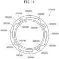
- FIG. 14 is a front view of the first or second annular member 313 or 314.
- Components of the fitting assembly substantially corresponding to ones according to the first embodiment are marked in FIGS. 12-14 with the same reference signs as the ones, and explanation on the components is omitted.
- the fitting assembly differs from one according to the first embodiment in a first annular member 313 and a second annular member 314.
- the first annular member 313 includes a fifth body 321 in addition to the first coupler 53.
- the fifth body 321 has an annular shape.
- the inner periphery of the fifth body 321 has a third thread 28.
- the first coupler 53 includes a third protrusion 322, third hooks 323, and first hook rests 324.
- the third protrusion 322 protrudes from the fifth body 321 to the axial direction of the first annular member 313.
- the third hooks 323 protrude from the third protrusion 322 to the axial direction of the first annular member 313.
- the first hook rests 324 extend on the third protrusion 322 in the circumferential direction of the first annular member 313. Circumferential spaces between the third hooks 323 serve as first passages 325.
- the fifth body 321 is mounted on the first port 11 to surround the whole circumference of the outer sleeve 41 of the first port 11 when the third thread 28 is engaged with the first thread 23.
- the fifth body 321 extends in the axial direction of the first annular member 313.
- the fifth body 321 is located on the second axial side (i.e. on the side nearer to the first fluid device 1) of the first annular member 313.
- the third protrusion 322 of the first coupler 53 is located on the first axial side (i.e. on the side farther from the first fluid device 1) of the first annular member 313.
- the third protrusion 322 protrudes from the first axial end of the fifth body 321 to the first axial direction of the first annular member 313.
- the third protrusion 322 has an annular shape and disposed coaxially with the fifth body 321.
- the third hooks 323 of the first coupler 53 are placed at the tip end of the third protrusion 322.
- the third hooks 323 protrude from the first axial end of the third protrusion 322 to the first axial direction of the first annular member 313.
- the tip end of each third hook 323 has a third corner.
- the first coupler 53 has at least one third hook, for example, four third hooks 323, which are arranged along the circumference of the third protrusion 322 (i.e. the first annular member 313) at certain intervals.
- the third hooks 323 are disposed radially inside the outer periphery of the third protrusion 322.
- the first hook rests 324 of the first coupler 53 are placed at the tip end of the third protrusion 322.
- the first hook rests 324 each extend along the circumference of the third protrusion 322.
- the first hook rests 324 are located on the inner periphery of the third protrusion 322 and protrude to the radial inside of the third protrusion 322.
- the first hook rests 324 are each adjacent to one of the first passages 325 in the circumferential direction of the third protrusion 322 between a pair of the third hooks 323.
- the first passages 325 each have a wall at the radial outside of one of the first hook rests 324.
- the first passages 325 extends in the direction in which the third hooks 323 protrude.
- the second annular member 314 has the same shape as the first annular member 313. This is not a limited condition.
- the second annular member 314 may differ in shape from the first annular member 313.
- the second annular member 314 has a sixth body 331 in addition to the second coupler 54.
- the sixth body 331 has an annular shape.
- the fourth thread 29 is placed at the inner periphery of the sixth body 331.
- the second coupler 54 includes a fourth protrusion 332, fourth hooks 333, and second hook rests 334.
- the fourth protrusion 332 protrudes from the sixth body 331 to the axial direction of the second annular member 314.
- the fourth hooks 333 protrude from the fourth protrusion 332 to the axial direction of the second annular member 314.
- the second hook rests 334 are placed along the circumference of the second annular member 314. Circumferential spaces between the fourth hooks 333 serve as second passages 335.
- the sixth body 331 is mounted on the second port 12 to surround the whole circumference of the outer sleeve 41 of the second port 12 when the fourth thread 29 is engaged with the second thread 26.
- the sixth body 331 extends in the axial direction of the second annular member 314.
- the sixth body 331 is placed on the second axial side (i.e. on the side nearer to the second fluid device 2) of the second annular member 314.
- the fourth protrusion 332 of the second coupler 54 is placed on the first axial side (i.e. on the side farther from the second fluid device 2) of the second annular member 314.
- the fourth protrusion 332 protrudes from the first axial end of the sixth body 331 to the first axial direction of the second annular member 314.
- the fourth protrusion 332 has an annular shape and disposed coaxially with the sixth body 331.
- the fourth hooks 333 of the second coupler 54 are placed at the tip end of the fourth protrusion 332.
- the fourth hooks 333 protrude from the first axial end of the fourth protrusion 332 to the first axial direction of the second annular member 314.
- the tip end of each fourth hook 333 has a fourth corner.
- the second coupler 54 has at least one fourth hook, for example, two fourth hooks 333, which are arranged along the circumference of the fourth protrusion 332 (i.e. the second annular member 314) at certain intervals.
- the fourth hooks 333 are located at the radial inside of the outer periphery of the fourth protrusion 332.
- the second hook rests 334 of the second coupler 54 are placed at the tip end of the fourth protrusion 332.
- the second hook rests 334 extends along the circumference of the fourth protrusion 332.
- the second hook rests 334 are located on the inner periphery of the fourth protrusion 332 and each protrude radially inward to be engaged with one of the fourth hooks 333.
- the second hook rests 334 are each adjacent to one of the second passages 335 in the circumferential direction of the fourth protrusion 332 between a pair of the fourth hooks 333.
- the second passages 335 each have a wall at the radial outside of one of the second hook rests 334.
- the second passages 335 extends in the direction in which the fourth hooks 333 protrude.
- a user rotatably couples the first annular member 313 with the second annular member 314 to make the third protrusion 322 and the fourth protrusion 332 face each other.
- the first annular member 313 is placed at the radial inside of the second annular member 314 to pass the third hooks 323 through the second passages 335 and pass the fourth hooks 333 through the first passages 325. After that, the user rotates the first annular member 313 relative to the second annular member 314.
- the third hooks 323 are engaged with the second hook rests 334, and the fourth hooks 333 are engaged with the first hook rests 324 to prevent the first and second annular member 313 and 314 from moving away from each other.
- the third hooks 323 are axially engaged with the second hook rests 334, and the fourth hooks 333 are axially engaged with the first hook rests 324.
- Engagement of the third hooks 323 with the second hook rests 334 forms the first and second sealing portions 31 and 32.
- the engagement causes the connector 15 to press its first protrusions 62 into the corresponding grooves 46 and press the tapered faces 65 of its second protrusions 63 onto the corresponding slopes 47 of the tip ends 44 of the inner sleeves 42.
- Engagement of the fourth hooks 333 with the first hook rests 324 forms the first and second sealing portions 31 and 32.
- the engagement causes the connector 15 to press its first protrusions 62 into the corresponding grooves 46 and press the tapered faces 65 of its second protrusions 63 onto the corresponding slopes 47 of the tip ends 44 of the inner sleeves 42.
- the first annular member 313 is made of certain resin, for example, fluoropolymer such as PFA, PVDF, ETFE, FEP, or PTFE.
- the second annular member 314 is made of certain resin, for example, fluoropolymer such as PFA, PVDF, ETFE, FEP, or PTFE.
- the user coaxially couples the first annular member 313 with the second annular member 314 to pass the third hooks 323 through the second passages 335 and pass the fourth hooks 333 through the first passages 325. After that, the user rotates the first annular member 313 relative to the second annular member 314. Thus, the third hooks 323 are engaged with the second hook rests 334, and the fourth hooks 333 are engaged with the first hook rests 324.
- first and second annular members 313 and 314 are fixed to each other not to axially move away from each other. This prevents the first and second ports 11 and 12 from moving away from each other and maintains the first and second fluid devices 1 and 2 connected with each other to allow fluid to flow between each other.
- the fitting assembly according to the sixth embodiment does not need any member such as a tube between the first and second fluid devices 1 and 2 for connection between the fluid devices to allow fluid to flow between each other. Accordingly, the fitting assembly enables the two fluid devices to be connected as closely to each other as possible and can reduce space for installation of the fluid devices 1 and 2. The fitting assembly can also prevent fluid leakage from the junction of the two fluid devices 1 and 2.
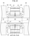
- FIG. 15 is a cross-sectional view of a fitting assembly for fluid device according to the first embodiment of the second example.
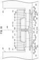
- FIG. 16 is a partially enlarged view of FIG. 15 .
- the fitting assembly is used to connect the first fluid device 401 with the second fluid device 402 to allow fluid to flow between the devices.
- the first fluid device 401 and the second fluid device 402 have shapes to be placed as closely to each other as possible.
- the first and second fluid devices 401 and 402 include, but are not limited to, devices with certain fluid channels such as valves, fluid meters, pumps, and fittings.
- the fitting assembly includes a first port 411, a second port 412, a first annular member 413, a second annular member 414, a connector 415, and a securing member 416.
- the first port 411 is installed at the first fluid device 401.
- the first port 411 is connected with the first fluid channel 421 of the first fluid device 401.
- the first port 411 has an annular shape.
- the second port 412 is installed at the second fluid device 402.
- the second port 412 is connected with the second fluid channel 425 of the second fluid device 402.
- the second port 412 has an annular shape.
- the first annular member 413 is mounted on the outer periphery of the first port 411.
- the second annular member 414 is mounted on the outer periphery of the second port 412.
- the connector 415 is installed between the first port 411 and the second port 412.
- the connector 415 seals a gap between the connector 415 and the first port 411 and seals a gap between the connector 415 and the second port 412.
- a first sealing portion 431 is a volume where a gap between the connector 415 and the first port 411 is sealed.
- a second sealing portion 432 is a volume where a gap between the connector 415 and the second port 411 is sealed.
- the securing member 416 secures one of the first annular member 413 and the second annular member 414 to the other to bring the one closer to the other when the connector 415 is installed between the first port 411 and the second port 412.
- the two fluid devices 401 and 402 make their respective ports 411 and 412 axially face each other.
- the first port 411 is installed at the first fluid device 401 and integrated with the casing 435 of the first fluid device 401. This is not a limited condition. The first port 411 may be separated from the casing 435.
- the first port 411 has an outer sleeve 441 and an inner sleeve 442.
- the outer sleeve 441 is a circular cylinder of substantially constant diameters, which is disposed around the opening of the first fluid channel 421 in the casing 435 to protrude to the outside of the casing 435.
- the outer sleeve 441 allows a portion of the connector 415 to enter the tip end (i.e. the first axial end) 443 of the outer sleeve 441.
- the outer sleeve 441 receives the portion of the connector 415, there is substantially no radial gap between the outer sleeve 441 and the portion of the connector 415.
- the outer sleeve 441 includes a first thread 423, which is located on the outer periphery of the outer sleeve 441 and extends along the axial direction of the outer sleeve 441.
- the first thread 423 is an external thread.
- the inner sleeve 442 is a circular cylinder of substantially constant outer diameters smaller than the inner diameter of the outer sleeve 441.
- the inner sleeve 442 is disposed around the opening of the first fluid channel 421 in the casing 435 to protrude in the same direction as the outer sleeve 441, i.e. in the first axial direction of the first port 411.
- the inner sleeve 442 is located inside the outer sleeve 441 and separated by a radial distance from the outer sleeve 441.
- the inner sleeve 442 extends coaxially with the outer sleeve 441.
- the tip end 444 of the inner sleeve 442 is located nearer to the casing 435 than the tip end 443 of the outer sleeve 441.
- the inner sleeve 442 protrudes from the casing 435 to a distance shorter than the outer sleeve 441.
- the first port 411 has a twofold-annular structure on the second axial side (i.e. the side nearer to the casing 435) of the outer sleeve 441.
- the inner sleeve 442 has substantially the same inner diameter as the first fluid channel 421 and the connector 415.
- the inner sleeve 442 is located between the first fluid device 401 and the connector 415 to connect the first fluid channel 421 with the internal space 448 of the connector 415, thus making the first port 411 connect the first fluid device 401 with the connector 415 to allow fluid to flow between them.
- annular groove 446 between the outer periphery of the inner sleeve 442 and the inner periphery of the outer sleeve 441.
- the groove 446 is open in the direction in which the outer and inner sleeves 441 and 442 protrude and extends along the whole circumference of the sleeves 441 and 442.
- the first port 411 is made of certain resin, for example, fluoropolymer such as PFA, PVDF, ETFE, FEP, or PTFE.
- the resin is not limited to fluoropolymer, but it may be PP or other resin.
- the second port 412 has a reflected shape of the first port 411 with respect to a virtual center plane 468. Since the second port 412 has substantially the same shape as the first port 411, components of the second port 412 corresponding to ones of the first port 411 are marked with the same reference signs as the corresponding ones of the first port 411, and explanation on the components is omitted. For the explanatory convenience, substantially the corresponding components can be marked with different reference signs, such as the first thread 423 and the second thread 426.
- the first annular member 413 surrounds the first port 411, esp. its outer sleeve 441 and is releasably fixed to (the outer sleeve 441 of) the first port 411.
- the first annular member 413 has an axial length shorter than the first thread 423 of the first port 411.
- the first annular member 413 is separated by an axial distance from the first fluid device 401.
- the first annular member 413 has a third thread 428, which is located on the inner periphery of the first annular member 413.
- the third thread 428 is engaged with the first thread 423.
- the first annular member 413 is, for example, a nut.
- the axial end nearer to the first fluid device 401 of the first annular member 413 has a tapered face 451, which reduces in diameter from the side nearer to the virtual center plane 468 (i.e. nearer to the second annular member 414) toward the first fluid device 401.
- the first annular member 413 protrudes to a radius shorter than the radius of the casing 435 of the first fluid device 401.
- the tapered face 451 and a below-described tapered face 452 may have reflected shapes of those shown in FIG. 16 .
- the tapered faces 451 and 452 may increase in diameter from the side nearer to the virtual center plane 468 toward the fluid device 401 or 402.
- the second annular member 414 surrounds the second port 412, esp. its outer sleeve 441 and is releasably fixed to (the outer sleeve 441 of) the second port 412.
- the second annular member 414 axially faces the first annular member 413.
- the second annular member 414 surrounds the outer sleeve 441 of the second port 412.
- the second annular member 414 is releasably mounted on the outer sleeve 441 of the second port 412.
- the second annular member 414 has an axial length shorter than the second thread 426 of the second port 412.
- the second annular member 414 is separated by an axial distance from the second fluid device 402.
- the second annular member 414 has a fourth thread 429, which is located on the inner periphery of the second annular member 414.
- the fourth thread 429 is engaged with the second thread 426.
- the second annular member 414 is, for example, a nut.
- the axial end nearer to the second fluid device 402 of the second annular member 414 has a tapered face 452, which reduce in diameter from the side nearer to the virtual center plane 468 (i.e. nearer to the first annular member 413) to the side nearer to the second fluid device 402.
- the second annular member 414 has a reflected shape of the first annular member 413 with respect to the virtual center plane 468.
- the second annular member 414 has substantially the same shape as the first annular member 413.
- the first annular member 413 is made of certain resin, for example, fluoropolymer such as PFA, PVDF, ETFE, FEP, or PTFE.
- the second annular member 414 is made of certain resin, for example, fluoropolymer such as PFA, PVDF, ETFE, FEP, or PTFE.
- the connector 415 has a first sealing portion 431 and a second sealing portion 432.
- the first sealing portion 431 seals a gap between the connector 415 and the first port 411.
- the second sealing portion 432 seals a gap between the connector 415 and the second port 412.
- the connector 415 has an annular shape.
- the connector 415 has a first portion 415a in contact with the first port 411 and a second portion 415b in contact with the second port 412. See FIG. 16 .
- the first portion 415a is a circular cylinder of substantially constant diameters and has a fluid channel, which is a portion of the internal space 448 of the connector 415.
- the first portion 415a is mounted on the first port 411 such that it is placed on the outer sleeve 441 to connect the fluid channel with the first fluid channel 421.
- the first portion 415a includes a body 461, a first protrusion 462, and a second protrusion 463.
- the body 461 is a circular cylinder, which is coupled with the outer sleeve 441 such that its outer periphery is surrounded by the outer sleeve 441 when the first portion 415a is mounted on the first port 411.
- the first protrusion 462 and the second protrusion 463 are located at an axial end (nearer to the first fluid device 401) of the body 461.
- the first and second protrusions 462 and 463 each have a circular ring shape.
- the whole circumference of the first protrusion 462 is pressed into the groove 446 of the first port 411 when the first portion 415a is mounted on the first port 411.
- the first protrusion 462 does not contact an inner face of the groove 446 on its side nearer to the first fluid device 401.
- the second protrusion 463 has a tapered face 465, which reduces in diameter from its side nearer to the virtual center plane 468 to its side nearer to the first fluid device 401.
- the tapered face 465 is located radially inside the first protrusion 462.
- the tapered face 465 axially faces the slope 447 of the inner sleeve 442.
- the tapered face 465 is pressed onto the slope 447 of the inner sleeve 442 when the first portion 415a is mounted on the first port 411.
- the connector 415 has a shape symmetric with respect to the virtual center plane 468, which is perpendicular to the axial direction of the connector 415 and located at the axial center of the connector 415. Since the first portion 415a has substantially the same shape as the second portion 415b, components of the second portion 415b and substantially the same ones of the first portion 415a are marked with the same reference signs, and details on the components are omitted.
- the connector 415 is made of certain resin, for example, fluoropolymer such as PFA, PVDF, ETFE, FEP, or PTFE, or other thermoplastic resin.
- fluoropolymer such as PFA, PVDF, ETFE, FEP, or PTFE, or other thermoplastic resin.
- the connector 415 is a body integrated with the first and second portions 415a and 415b, which have substantially the same shape.
- the connector 415 may be an assembly of first and second portions, which differ in shape.
- the securing member 416 secures one of the first and second annular members 413 and 414 to the other when the third thread 428 of the first annular member 413 is engaged with the first thread 423 of the first port 411 and the fourth thread 429 of the second annular member 414 is engaged with the second thread 426 of the second port 412.
- the two fluid devices 401 and 402 make their respective ports 411 and 412 face each other.
- the securing member 416 is, for example, a clump. As shown in FIG. 17 , the clump has a pair of clump pieces 471 and 472 and two pairs of bolts 473 and annular members 474 such as nuts.
- the clump pieces 471 and 472 each have substantially a semicircular shape.
- the pair of the clump pieces 471 and 472 is combined to form a circle.
- the pair of the clump pieces 471 and 472 (the securing member 416) are arranged coaxially with the first and second annular member 413 and 414.
- each clump piece 471 or 472 has a slope 476 or 477, which contacts the tapered face 451 or 452 of the first or second annular member 413 or 414.
- the slope 476 or 477 faces the tapered face 451 or 452 in the axial direction of the securing member 416 (i.e. the pair of the clump pieces 471 and 472).
- the slope 476 is located nearer to the first fluid device 401 than the first annular member 413.
- the slope 476 is substantially parallel to the tapered face 451.
- the slope 476 reduces in diameter from the side nearer to the virtual center plane 468 (i.e. nearer to the second annular member 414) to the side nearer to the first fluid device 401.
- the slope 477 is located nearer to the second fluid device 402 than the second annular member 414.
- the slope 477 is substantially parallel to the tapered face 452.
- the slope 477 reduces in diameter from the side nearer to the virtual center plane 468 (i.e. nearer to the first annular member 413) to the side nearer to the second fluid device 402.
- the clump piece 471 makes the slope 476 contact the tapered face 451.
- the clump piece 472 makes the slope 477 contact the tapered face 452.
- the first and second annular members 413 and 414 are placed.
- the annular members 474 at both longitudinal (or circumferential) ends of the clump pieces 471 and 472 are secured with the bolts 473.
- the above-described structure connects the first fluid device 401 with the second fluid device 402 to allow fluid to flow between them.
- the clump serving as the securing member 416 is placed radially outside the first and second ports 411 and 412.
- the securing member 416 acts force to secure the first and second annular members 413 and 414 to the virtual center plane 468, which is located axially inside the first and second annular members 413 and 414.
- the first protrusion 462 of the connector 415 is pressed into the groove 446, and the tapered face 465 of the second protrusion 463 is pressed onto the tip end 444 and the slope 447 of the inner sleeve 442.
- first sealing portion 431 seals the gap between the connector 415 and the first port 411
- second sealing portion 432 seals the gap between the connector 415 and the second port 412.
- the first and second sealing portions 431 and 432 each form a primary sealing area 481 and a secondary sealing area 482.
- the primary sealing area 481 acts axially sealing force
- the secondary sealing area 482 acts radially sealing force.
- the securing member 416 is further secured with the bolt 473. Accordingly, the first annular member 413 axially approaches the second annular member 414. Thus, the slopes 476 and 477 are further pressed onto the tapered faces 451 and 452. As a result, the tapered face 465 of each second protrusion 463 is further pressed onto the slope 447 of the tip end 444 of the inner sleeve 442.
- the fitting assembly according to the first embodiment of the second example can prevent fluid leakage from the junction of the two fluid devices 401 and 402.
- the fitting assembly does not need any member such a tube between the first and second fluid devices 401 and 402 to connect the first fluid device 401 with the second fluid device 402 to allow fluid to flow between them. Accordingly, the fitting assembly enables the two fluid devices 401 and 402 to be placed as closely to each other as possible and connect one with the other to allow fluid to flow between them. This can reduce space for installation of the fluid devices 401 and 402.
- the first and second fluid devices 401 and 402 can be moved by the first and second annular members 413 and 414 moving when the securing member 416 is being secured with the bolts 473. This is not a limited condition.
- the first and second fluid devices may be fixed to somewhere not to be moved by the first and second annular members 413 and 414. Even in this case, the example is also applicable.
- the connector 415 has an extending portion 488, which is located between the first port 411 and the second port 412 when the first fluid device 401 is connected with the second fluid device 402 to allow fluid to flow between each other.
- the extending portion 488 is separated from both the first and second ports 411 and 412.
- the extending portion 488 is a ring extending radially outside the connector 415.
- the extending portion 488 has an outer diameter larger than the tip ends 443 of the first and second ports 411 and 412.
- the extending portion 488 is located on the virtual center plane 468 of the connector 415 and at the axial intermediate portion of the connector 415, i.e. the boundary between the first and second portions 415a and 415b of the connector 415.
- the extending portion 488 is located between the tip ends 443 and 443 of the first and second ports 411 and 412 when the connector 415 is mounted on the first and second ports 411 and 412.
- the extending portion 488 axially faces the tip ends 443 and 443 of the first and second ports 411 and 412.
- the extending portion 488 facilitates release of the connector 415 from the first and second ports 411 and 412.
- the securing member 416 is the above-described clump. This is not a limited condition.
- the securing member may be a clump with a pair of clump pieces rotatably coupled with each other with a pivot pin. The clump secures the pair of clump pieces stacked one on top of another with bolts and nuts.
- FIGS. 18-21 Components of fitting assemblies substantially corresponding to ones of the fitting assembly according to the first embodiment of the second example are marked in FIGS. 18-21 with the same reference signs as the ones, and explanation on the components is omitted.
- FIG. 18 is a cross-sectional view of a fitting assembly for fluid device according to the second embodiment of the second example.
- the fitting assembly differs from one according to the first embodiment of the second example in the following configuration: a first sealing portion 521 that seals a gap between the first port 511 and the connector 515; and a second sealing portion 522 that seals a gap between the second port 512 and the connector 515.
- the first port 511 is installed at the first fluid device 401 and integrated with the casing 435 of the first fluid device 401.
- the first port 511 has an annular body 525 and a protruding ring 526.
- the annular body 525 is a circular cylinder of substantially constant inner diameters, which is installed around the opening of the first fluid channel 421 in the casing 435 to protrude toward the outside of the casing 435.
- the annular body 525 allows a portion of the connector 515 to enter the tip end (i.e. the first axial end) of the annular body 525. When the annular body 525 receives the portion of the connector 515, there is substantially no gap between the annular body 525 and the portion of the connector 515.
- the outer periphery of the annular body 525 has a first thread 423 extending in the axial direction of the annular body 525.
- the first thread 423 is an external thread.
- the protruding ring 526 is a ring of an outer diameter smaller than the inner diameter of the annular body 525.
- the protruding ring 526 is placed around the opening of the first fluid channel 421 in the casing 435 to protrude to the same direction as the annular body 525 (i.e. to the first axial direction of the annular body 525).
- the protruding ring 526 is located inside the annular body 525 to be separated by a radial distance from the annular body 525.
- the protruding ring 526 has substantially the same inner diameter as the first fluid channel 421 and the connector 515.
- the protruding ring 526 is placed between the first fluid device 401 and the connector 515 to connect the first fluid channel 421 with the internal space 538 of the connector 515.
- the port 511 connects the first fluid device 401 with the connector 515 to allow fluid to flow between them.
- the outer periphery of the protruding ring 526 includes a tapered face 528, which reduces in diameter to the direction in which the protruding ring 526 protrudes, i.e. to the first axial direction of the first port 511.
- the tapered face 528 extends along the whole circumference of the protruding ring 526 and is separated by a distance from the inner periphery of the annular body 525.
- the second port 512 has substantially the same shape as the first port 511. Accordingly, components of the second port 512 substantially corresponding to ones of the first port 511 are marked with the same reference signs as the ones, and explanation on the components is omitted. For explanatory convenience, substantially the same components can be marked with different reference signs, such as the first thread 423 and the second thread 426.
- the connector 515 has a first portion 515a in contact with the first port 511 and a second portion 515b in contact with the second port 512.
- the first portion 515a is a circular cylinder of substantially constant inner diameters, whose internal space serves as a fluid channel.
- the first portion 515a is mounted on the first port 511 such that it is placed on the annular body 525 to connect its fluid channel with the first fluid channel 421.
- the first portion 515a includes a body 531 and a protrusion 532.
- the body 531 is a circular cylinder, which is placed on the inner periphery of the annular body 525 when the first portion 515a is mounted on the first port 511.
- the protrusion 532 axially protrudes from the first axial end (i.e. the end nearer to the first fluid device 401) of the body 531.
- the protrusion 532 has a circular ring shape with a slope 535 on the inner periphery of the protrusion 532.
- the protrusion 532 presses the slope 535 onto the tapered face 528 of the protruding ring 526 when the first portion 515a is mounted on the first port 511.
- the slope 535 increases in diameter to the direction in which the protrusion 532 protrudes (i.e. toward the first fluid device 401).
- the slope 535 extends along the whole circumference of the protrusion 532.
- the connector 515 has a shape symmetric with respect to a virtual center plane 548, which is perpendicular to the axial direction of the connector 515 and located at the axial center of the connector 515.
- the first portion 515a and the second portion 515b have substantially the same shape.
- the fitting assembly can reduce space for installation of the first fluid device 401 and the second fluid device 402 connected with each other to allow fluid to flow between each other.
- the connector 515 forms a first sealing portion 521 and a second sealing portion 522 during connection between the first and second fluid devices 401 and 402.
- the connector 515 presses the slope 535 of the first portion 515a onto the tapered face 528 of the first port 511 and presses the slope 535 of the second portion 515b onto the tapered face 528 of the second port 512.
- FIG. 19 is a cross-sectional view of a fitting assembly for fluid device according to a third embodiment of the second example. As shown in FIG. 19 , the fitting assembly differs from one according to the first embodiment of the second example in the following configuration: a first sealing portion 561 that seals a gap between the first portion 551 and the connector 555; and a second sealing portion 562 that seals a gap between the second portion 552 and the connector 555.
- the first portion 551 is installed at the first fluid device 401 and integrated with the casing 435 of the first fluid device 401.
- the outer periphery of the first port 551 has a first thread 423 extending along the axial direction of the first port 551.
- the first thread 423 is an external thread.
- the first port 551 has an annular body 565 and a protrusion 566.
- the annular body 565 is a circular cylinder with a step on its inner periphery.
- the annular body 565 protrudes away from the casing 435.
- the annular body 565 is located around the opening of the first fluid channel 421 in the casing 435.
- the annular body 565 has a first annular portion 565a on the first axial side (i.e. the side nearer to the opening of the first port 551) of the step 567.
- the first annular portion 565a allows a portion of the connector 555 to enter the first annular portion 565a.
- the first annular portion 565a closely contacts substantially the whole outer periphery of the portion of the connector 555.
- the annular body 565 has a second annular portion 565b on the second axial side (i.e. the side nearer to the first fluid device 401) of the step 567.
- the second annular portion 565b has substantially the same inner diameter as the first fluid channel 421 and the connector 555.
- the second annular portion 565b is disposed between the first fluid device 401 and the connector 555 to connect the first fluid channel 421 with the internal space 578 of the connector 555, and thereby, to make the first port 551 connect the first fluid device 401 with the connector 555 to allow fluid to flow between them.
- the protrusion 566 is a ring protruding from the first annular portion 565a to the first axial direction of the annular body 565.
- the inner periphery of the protrusion 566 has a slope 568, which increases in diameter from the annular body 565 to the tip end of the protrusion 566, i.e. to the opening of the first port 551.
- the slope 568 extends along the whole circumference of the protrusion 566.
- the second port 552 has a reflected shape of the first port 551 with respect to the virtual center plane 598, i.e. substantially the same shape as the first port 551.
- the connector 555 has a first portion 555a in contact with the first port 551 and a second portion 555b in contact with the second port 552.
- the first portion 555a is a circular cylinder of substantially constant inner diameters, whose internal space serves as a fluid channel.
- the first portion 555a is placed on the annular body 565 and mounted on the first port 551 to connect the internal space 578, which serves as the fluid channel, with the first fluid channel 421.
- the first portion 555a has a body 571 and a protrusion 572.
- the body 571 is a circular cylinder, which is coupled with the annular body 565 to be surrounded by the annular body 565 when the first portion 555a is mounted on the first port 551.
- the protrusion 572 protrudes from an end of the body 571 (i.e. an axially intermediate portion of the connector 555) to the radial outside of the connector 555.
- the protrusion 572 has a circular ring shape with a tapered face 575 on the outer periphery of the protrusion 572.
- the protrusion 572 presses the tapered face 575 onto the slope 568 of the protrusion 566.
- the tapered face 575 increases in diameter from the side nearer to the annular body 565 to the opposite side.
- the tapered face 575 extends along the whole circumference of the protrusion 572.
- the connector 555 has a shape symmetric with respect to the virtual center plane 598, which is perpendicular to the axial direction of the connector 555 and located at the axial center of the connector 555.
- the first portion 555a and the second portion 555b have substantially the same shape.
- the connector 555 forms the first sealing portion 561 and the second sealing portion 562 during connection between the first and second fluid devices 401 and 402.
- the connector 555 presses the tapered face 575 of the first portion 555a onto the slope 568 of the first port 551 and presses the tapered face 575 of the second portion 555b onto the slope 568 of the second port 552. This prevents fluid leakage from the junction of the first and second fluid devices 401 and 402 and achieves short-distance connection between the first and second fluid devices 401 and 402 without any member such as tubes.
- the fitting assembly can reduce space for installation of the first and second fluid devices 401 and 402 connected with each other to allow fluid to flow between each other.
- FIG. 20 is a cross-sectional view of a fitting assembly for fluid device according to a fourth embodiment of the second example. As shown in FIG. 20 , the fitting assembly differs from one according to the first embodiment of the second example in the following configuration: a first sealing portion 621 that seals a gap between the first portion 611 and the connector 615; and a second sealing portion 622 that seals a gap between the second portion 612 and the connector 615.
- the first port 611 is installed at the first fluid device 401 and integrated with the casing 435 of the first fluid device 401.
- the first port 611 has an outer sleeve 625 and an inner sleeve 626.
- the outer sleeve 625 is a circular cylinder of substantially constant inner diameters and protrudes from the vicinity of the first fluid channel 421 in the casing 435 to the outside of the casing 435.
- the outer sleeve 625 allows a portion of the connector 615 to enter the tip end (i.e. the first axial end) of the outer sleeve 625.
- the outer periphery of the outer sleeve 625 has a first thread 423 extending along the axial direction of the outer sleeve 625.
- the first thread 423 is an external thread.
- the inner sleeve 626 is a circular cylinder of substantially constant outer diameters smaller than the inner diameter of the outer sleeve 625.
- the inner sleeve 626 protrudes from the vicinity of the first fluid channel 421 in the casing 435 to the direction in which the outer sleeve 625 protrudes, i.e. to the first axial direction of the first port 611.
- the inner sleeve 626 is placed inside the outer sleeve 625 to be separated by a radial distance from the outer sleeve 625.
- the tip end of the inner sleeve 626 is located farther from the first or second fluid device 401 or 402 than the tip end of the outer sleeve 625.
- the inner sleeve 626 protrudes from the casing 435 to a distance longer than the outer sleeve 625.
- the first port 611 has a twofold-annular structure at an axial intermediate portion of the outer sleeve 625.
- the inner sleeve 626 has substantially the same inner diameter as the first fluid channel 421 and the connector 615.
- the inner sleeve 626 is placed between the first fluid device 401 and the connector 615 to connect the first fluid channel 421 with the internal space of the connector 615.
- the first port 611 connects the first fluid device 401 with the connector 615 to allow fluid to flow between them.
- the tip end of the inner sleeve 626 is tapered in the direction in which the inner sleeve 626 protrudes.
- the outer periphery of the tip end of the inner sleeve 626 has a tapered face 628, which reduces in diameter to the direction in which the inner sleeve 626 protrudes, i.e. to the first axial direction of the first port 611, or toward the virtual center plane 648.
- the tapered face 628 extends along the whole circumference of the tip end of the inner sleeve 626.
- the second port 612 has substantially the same shape as the first port 611.
- the connector 615 has a first portion 615a in contact with the first port 611 and a second portion 615b in contact with the second port 612.
- the first portion 615a is a circular cylinder, whose internal space serves as a fluid channel.
- the first portion 615a is mounted on the first port 611 such that it is coupled with the inner sleeve 626 to connect its fluid channel with the first fluid channel 421.
- the first portion 615a includes a body 631 and a protrusion 632.
- the body 631 is a circular cylinder, which is placed on the outer periphery of the inner sleeve 626 when the first portion 615a is mounted on the first port 611.
- the protrusion 632 protrudes from an axial end of the body 631, i.e. an axial intermediate portion of the connector 615 to the radial inside of the connector 615.
- the protrusion 632 has a circular ring shape with a slope 635 on the inner periphery of the protrusion 632.
- the protrusion 632 presses the slope 635 onto the tapered face 628 of the inner sleeve 626 when the first portion 615a is mounted on the first port 611.
- the slope 635 increases in diameter from the virtual center plane 648 toward the first or second fluid device 401 or 402.
- the slope 635 extends along the whole circumference of the protrusion 632.
- the connector 615 has a shape symmetric with respect to the virtual center plane 648, which is perpendicular to the axial direction of the connector 615 and located at the axial center of the connector 615.
- the first and second portions 615a and 615b have substantially the same shape.
- the fitting assembly makes the connector 615 form the first sealing portion 621 and the second sealing portion 622 during connection between the first and second fluid devices 401 and 402.
- the connector 615 presses the slope 635 of the first portion 615a onto the tapered face 628 of the first port 611 and presses the slope 635 of the second portion 615b onto the tapered face 628 of the second port 612. This prevents fluid leakage from the junction of the first and second fluid devices 401 and 402 and achieves short-distance connection between the first and second fluid device 401 and 402 without any member such as a tube.
- the fitting assembly can reduce space for installation of the first and second fluid devices 401 and 402 connected with each other to allow fluid to flow between each other.
- FIG. 21 is a cross-sectional view of a fitting assembly for fluid device according to a fifth embodiment of the second example.
- the fitting assembly differs from one according to the first embodiment of the second example in a securing member 666 and portions relating to it, i.e. a first annular member 663 and a second annular member 664.
- the first annular member 663 has two or more first through holes 671 along its circumference.
- the first through holes 671 each extend in the same direction as an axial opening of the first annular member 663, i.e. a third thread 428.
- the first through holes 671 are aligned along a circumference radially outside the opening of the first annular member 663 at certain intervals.
- the second annular member 664 has two or more second through holes 672 along its circumference.
- the second through holes 672 each extend in the same direction as an axial opening of the second annular member 664, i.e. a fourth thread 429.
- the second through holes 672 are aligned along a circumference radially outside the opening of the second annular member 664 at certain intervals.
- the securing members 666 are bolts 683 and annular members 684 such as nuts.
- the bolts 683 are each placed in a coaxially-arranged pair of the first through hole 671 and the second through hole 672.
- the annular members 684 are secured to the bolts 683 protruding from the first or second through hole 671 or 672.
- the securing members 666 secure the first annular member 663 to the second annular member 664 at the radial outside of the first and second ports 411 and 412. As the bolts 683 rotate, the first annular member 663 approaches the second annular member 664.
- the fitting assembly does not need any member such as a tube between the first and second fluid devices 401 and 402 to connect the first fluid device 401 with the second fluid device 402 to allow fluid to flow between them.
- the fitting assembly can prevent fluid leakage from the junction of the two fluid devices 401 and 402, and in addition, can reduce space for installation of the two fluid devices 401 and 402.
- FIG. 22 is a cross-sectional view of a fitting assembly for fluid device according to the first embodiment of the third example.
- FIG. 23 is a partially enlarged view of FIG. 22 .
- FIG. 24 is a diagram showing two fluid devices of the fitting assembly in FIG. 22 separated from each other.
- FIG. 25 is a diagram showing the two fluid devices of the fitting assembly in FIG. 22 during a process of connecting one of them with the other.
- the fitting assembly is used to connect a first fluid device 701 with a second fluid device 702 to allow fluid to flow between them.
- the first and second fluid devices 701 and 702 have shapes to be placed closely to each other.
- the first and second fluid devices 701 and 702 include, but are not limited to, devices with certain fluid channels such as valves, fluid meters, pumps, and fittings.
- the fitting assembly has a first port 711, a second port 712, a first annular member 713, a second annular member 714, and a connector 715.
- the first port 711 is installed at the first fluid device 701.
- the first port 711 is connected with the first fluid channel 721 of the first fluid device 701.
- the first port 711 has an annular shape.
- the second port 712 is installed at the second fluid device 702.
- the second port 712 is connected with the second fluid channel 725 of the second fluid device 702.
- the second port 712 has an annular shape.
- the first annular member 713 is installed at the first port 711.
- the outer periphery of the first annular member 713 has a first coupler 753.
- the second annular member 714 is installed at the second port 712.
- the inner periphery of the second annular member 714 has a second coupler 754.
- the connector 715 is located between the first port 711 and the second port 712.
- the connector 715 seals a gap between the connector 715 and the first port 711 and seals a gap between the connector 715 and the second port 712.
- the first annular member 713 is fixed to the second annular member 714 with the first coupler 753 and the second coupler 754.
- the two fluid devices 701 and 702 are placed such that their respective ports 711 and 712 axially face each other.
- the first port 711 is installed at the first fluid device 701.
- the first port 711 is integrated with the casing 735 of the first fluid device 701. This is not a limited condition.
- the first port 711 may be separated from the casing 735.
- the first port 711 has an outer sleeve 741 and an inner sleeve 742.
- the outer sleeve 741 is a circular cylinder of substantially constant inner diameters.
- the outer sleeve 741 protrudes from the vicinity of the opening of the first fluid channel 721 in the casing 735 to the outside of the casing 735.
- the outer sleeve 741 allows a portion of the connector 715 to enter the tip end (i.e. the first axial end) 743 of the outer sleeve 741.
- the outer sleeve 741 receives the portion of the connector 715, there is substantially no radial gap between the outer sleeve 741 and the portion of the connector 715.
- the outer sleeve 741 includes a first thread 723, which extends on the outer periphery of the outer sleeve 741 along the axial direction of the outer sleeve 741.
- the first thread 723 is an external thread.
- the inner sleeve 742 is a circular cylinder of substantially constant outer diameters smaller than the inner diameter of the outer sleeve 741.
- the inner sleeve 742 protrudes from the vicinity of the opening of the first fluid channel 721 in the casing 735 to the same direction as the outer sleeve 741, i.e. to the first axial direction of the first port 711.
- the inner sleeve 742 is placed inside the outer sleeve 741 to be separated by a radial distance from the outer sleeve 741.
- the tip end 744 of the inner sleeve 742 is located nearer to the casing 735 than the tip end 743 of the outer sleeve 741.
- the inner sleeve 742 protrudes from the casing 735 to a distance shorter than the outer sleeve 741.
- the first port 711 has a twofold-annular structure on the second axial side (i.e. the side nearer to the casing 735) of the outer sleeve 741.
- the inner sleeve 742 has substantially the same inner diameter as the first fluid channel 721 and the connector 715.
- the inner sleeve 742 is disposed between the first fluid device 701 and the connector 715 to connect the first fluid channel 721 with the internal space 748 of the connector 715, and thus, to make the first port 711 connect the first fluid device 701 with the connector 715 to allow fluid to flow between them.
- the groove 746 is open to the direction in which the outer and inner sleeves 741 and 742 protrude, i.e. to the side nearer to the second port 712.
- the groove 746 extends along the whole circumference of the outer and inner sleeves 741 and 742.
- the inner sleeve 742 has a slope 747 near the tip end 744 of the inner sleeve 742. The slope 747 increases in diameter from the side nearer to the first fluid channel 721 toward the tip end 744 of the inner sleeve 742.
- the first port 711 is made of certain resin, for example, fluoropolymer such as PFA, PVDF, ETFE, FEP, or PTFE.
- the resin is not limited to fluoropolymer and may be other resin such as PP.
- the second port 712 is a reflected shape of the first port 711 with respect to the virtual center plane 768. Since the second port 712 has substantially the same shape as the first port 711, components of the second port 712 corresponding to ones of the first port 711 are marked with the same reference signs as the ones. Explanation of the components is omitted. For explanatory convenience, substantially the same components can be marked with different reference signs, such as the first thread 723 and the second thread 726.
- the connector 715 has a first sealing portion 731 and a second sealing portion 732.
- the first sealing portion 731 seals a gap between the connector 715 and the first port 711.
- the second sealing portion 732 seals a gap between the connector 715 and the second port 712.
- the connector 715 has an annular shape.
- the connector 715 has a first portion 715a in contact with the first port 711 and a second portion 715b in contact with the second port 712. See FIG. 23 .
- the first portion 715a is a circular cylinder of substantially constant inner diameters and has a fluid channel, which is a portion of the internal space 748 of the connector 715.
- the first portion 715a is mounted on the first port 711 such that it is placed on the outer sleeve 741 to connect the fluid channel of the first portion 715a with the first fluid channel 721.
- the first portion 715a includes a body 761, a first protrusion 762, and a second protrusion 763.
- the body 761 is a circular cylinder, which is coupled with the whole circumference of the outer sleeve 741 to be surrounded by the outer sleeve 741 when the first portion 715a is mounted on the first port 711.
- the first and second protrusions 762 and 763 are placed on an axial end (i.e. the end nearer to the first fluid device 701) of the body 761.
- the first and second protrusions 762 and 763 each have a circular ring shape. The whole circumference of the first protrusion 762 is pressed into the groove 746 of the first port 711 when the first portion 715a is mounted on the first port 711. The first protrusion 762 is separated from an inner side nearer to the first fluid device 701 of the groove 746.
- the second protrusion 763 has a tapered face 765, which reduces in diameter from the side nearer to the virtual center plane 768 toward the first fluid device 701.
- the tapered face 765 is located inside the first protrusion 762 in the radial direction of the first portion 715a.
- the tapered face 765 faces the slope 747 of the inner sleeve 742 in the axial direction of the first portion 715a.
- the tapered face 765 is pressed onto the slope 747 of the inner sleeve 742 when the first portion 715a is mounted on the first port 711.
- the connector 715 has a shape symmetric with respect to the virtual center plane 768, which is perpendicular to the axial direction of the connector 715 and located at the axial center of the connector 715. Since the second portion 715b has substantially the same shape as the first portion 715a, components of the second portion 715b corresponding to ones of the first portion 715a are marked with the same reference signs as the ones, and explanation on the components is omitted.
- the connector 715 is made of certain resin, for example, fluoropolymer such as PFA, PVDF, ETFE, FEP, or PTFE, or other thermoplastic resin.
- fluoropolymer such as PFA, PVDF, ETFE, FEP, or PTFE, or other thermoplastic resin.
- the connector 715 is a body integrated with the first and second portions 715a and 715b, which have substantially the same shape.
- the connector 715 may be an assembly of first and second portions, which differ in shape.
- the first annular member 713 is releasably fixed to (the outer sleeve 741 of) the first port 711 such that it surrounds the first port 711, esp. its outer sleeve 741.
- the first annular member 713 has, in addition to the first coupler 753, a third thread 728 to be engaged with the first thread 723 of the first port 711.
- the third thread 728 is located on the inner periphery of the first annular member 713.
- the first coupler 753 is located on the outer periphery of the first annular member 713.
- the second annular member 714 is releasably fixed to (the outer sleeve 741 of) the second port 712 such that it surrounds the second port 712, esp. its outer sleeve 741.
- the second annular member 714 has, in addition to the second coupler 754, a fourth thread 729 to be engaged with the second thread 726 of the second port 712.
- the fourth thread 729 is located on the inner periphery of the second annular member 714.
- the second coupler 754 is located on the inner periphery of the second annular member 714.
- the first annular member 713 is mounted on the first port 711 such that it surrounds the whole circumference of the outer sleeve 741 of the first port 711 when the third thread 728 is engaged with the first thread 723.
- the third thread 728 is an internal thread.
- the third thread 728 is located on the side nearer to the first fluid device 701 (i.e. the second axial side) of the first annular member 713.
- the first coupler 753 is located on the side farther from the first fluid device 701 (i.e. the first axial side) of the first annular member 713.
- the first coupler 753 has a fifth thread 756 on the outer periphery of the first annular member 713.
- the fifth thread 756 is an external thread extending in the axial direction of the first annular member 713.
- the second annular member 714 is mounted on the second port 712 such that it surrounds the whole circumference of the outer sleeve 741 of the second port 712 when the fourth thread 729 is engaged with the second thread 726.
- the fourth thread 729 is an internal thread, which is located on the side nearer to the second fluid device 702 (i.e. the second axial side) of the second annular member 714.
- the second coupler 754 is located on the side farther from the second fluid device 702 (i.e. the first axial side) of the second annular member 714.
- the second coupler 754 has a sixth thread 757 on the inner periphery of the second annular member 714.
- the sixth thread 757 is an internal thread extending in the axial direction of the second annular member 714.
- the sixth thread 757 is engaged with the fifth thread 756 of the first annular member 713 to prevent the second annular member 714 from being separated from the first annular member 713.
- the fifth and sixth threads 756 and 757 wrap in the direction opposite to the direction in which the second and fourth threads 726 and 729 wrap. Handedness of the fifth and sixth threads 756 and 757 is the reverse of handedness of the second and fourth threads 726 and 729.
- the second annular member 714 has a base 758 with the fourth thread 729 and a tip 759 with the sixth thread 757.
- the base 758 has an inner diameter smaller than the tip 759. In contrast to the tip 759, the base 758 is located on the second axial side of the second annular member 714.
- the sixth thread 757 engaged with the fifth thread 756 of the first annular member 713 fixes the tip 759 to the first annular member 713 such that the tip 759 almost surrounds the fifth thread 756.
- the first annular member 713 is made of certain resin, for example, fluoropolymer such as PFA, PVDF, ETFE, FEP, or PTFE.
- the second annular member 714 is made of certain resin, for example, fluoropolymer such as PFA, PVDF, ETFE, FEP, or PTFE.
- the above-described configuration connects the first fluid device 701 with the second fluid device 702 to allow fluid to flow between them.
- the sixth thread 757 of the second annular member 714 is engaged with the fifth thread 756 of the first annular member 713.
- the second annular member 714 is fixed to the first annular member 713.
- the first protrusion 762 of the connector 715 is pressed into the groove 746, and the tapered face 765 of the second protrusion 763 is pressed onto the tip end 444 and slope 747 of the inner sleeve 742.
- a user connects the first fluid device 701 with the second fluid device 702 as follows. First, as shown in FIG. 24 , the user engages the third thread 728 with the first thread 723 to releasably fix the first annular member 713 to the first port 711. The user engages the fourth thread 729 with the second thread 726 to releasably fix the second annular member 714 to the second port 712.
- the user inserts the connector 715 into one of the first port 711 and the second port 712. Then, as shown in FIG. 25 , while the user makes the first and second fluid devices 701 and 702 separated from each other face each other, the user brings the connector 715 close to the other of the first and second ports 711 and 712.
- the user inserts the connector 715 into the other of the first and second ports 711 and 712 and brings the first annular member 713 close to the second annular member 714. Then, the user engages the fifth thread 756 with the sixth thread 757 and couples the first annular member 713 with the second annular member 714. Thus, the user secures the first annular member 713 to the second annular member 714 with the fifth and sixth threads 756 and 757.
- first sealing portion 731 seals the gap between the connector 715 and the first port 711
- second sealing portion 732 seals the gap between the connector 715 and the second port 712.
- the first and second sealing portions 731 and 732 each form a primary sealing area 781 acting axial sealing force and a secondary sealing area 782 acting radial sealing force.
- the fitting assembly can prevent fluid leakage from the junction of the two fluid devices 701 and 702.
- the fitting assembly does not need any member such as a tube between the first and second fluid devices 701 and 702 to connect the first fluid device 701 with the second fluid device 702 to allow fluid to flow between them.
- the two fluid devices 701 and 702 are placed as closely to each other as possible. This can reduce space for installation of the fluid devices 701 and 702.
- the connector 715 has an extending portion 788, which is located between the first port 711 and the second port 712 when the first fluid device 701 is connected with the second fluid device 702 to allow fluid to flow between each other.
- the extending portion 788 is separated from both the first and second ports 711 and 712.
- the extending portion 788 has a ring shape extending radially outside the connector 715.
- the extending portion 788 has an outer diameter larger than the tip ends 743 of the first and second ports 711 and 712.
- the extending portion 788 is placed on the virtual center plane 768 of the connector 715 and at the axial intermediate portion of the connector 715, i.e. at the boundary between the first and second portions 715a and 715b of the connector 715.
- the extending portion 788 is disposed between the tip ends 743 and 743 of the first and second ports 711 and 712 when the connector 715 is mounted on the ports 711 and 712.
- the extending portion 788 axially faces the tip ends 743 and 743 of the first and second ports 711 and 712.
- the extending portion 788 facilitates release of the connector 715 from the first and second ports 711 and 712.
- FIGS. 26-28 Components of fitting assemblies substantially corresponding to ones of the fitting assembly according to the first embodiment of the third example are marked in FIGS. 26-28 with the same reference signs as the ones, and explanation on the components is omitted.
- FIG. 26 is a cross-sectional view of a fitting assembly for fluid device according to a second embodiment of the third example. As shown in FIG. 26 , the fitting assembly differs from one according to the first embodiment of the third example in the following configuration: a first sealing portion 821 that seals a gap between the first port 811 and the connector 815; and a second sealing portion 822 that seals a gap between the second port 812 and the connector 815.
- the first port 811 is installed on the first fluid device 701 and integrated with the casing 735 of the first fluid device 701.
- the first port 811 has an annular body 825 and a protruding ring 826.
- the annular body 825 is a circular cylinder of substantially constant inner diameters, which is placed around the opening of the first fluid channel 721 in the casing 735 to protrude to the outside of the casing 735.
- the annular body 825 allows a portion of the connector 815 to enter the tip end (i.e. the first axial end) of the annular body 825.
- the outer periphery of the annular body 825 has a first thread 723 extending along the axial direction of the annular body 825.
- the first thread 723 is an external thread.
- the protruding ring 826 is a ring of an outer diameter smaller than the inner diameter of the annular body 825.
- the protruding ring 826 is disposed around the opening of the first fluid channel 721 in the casing 735 to protrude in the same direction as the annular body 825, i.e. in the first axial direction of the annular body 825.
- the protruding ring 826 is located inside the annular body 825 and separated by a radial distance from the annular body 825.
- the protruding ring 826 has substantially the same inner diameter as the first fluid channel 721 and the connector 815.
- the protruding ring 826 is disposed between the first fluid device 701 and the connector 815 to connect the first fluid channel 721 with the internal space 838 of the connector 815.
- the first port 811 connects the first fluid device 701 with the connector 815 to allow fluid to flow between them.
- the outer periphery of the protruding ring 826 includes a tapered face 828, which reduces in outer diameter to the direction in which the protruding ring 826 protrudes, i.e. to the first axial direction of the first port 811.
- the tapered face 828 extends along the whole circumference of the outer periphery of the protruding ring 826.
- the tapered face 828 is separated by a distance from the inner periphery of the annular body 825.
- the second port 812 has substantially the same shape as the first port 811. Accordingly, components of the second port 812 substantially corresponding to ones of the first port 811 are marked with the same reference signs as the ones, and explanation on the components is omitted. For the explanatory convenience, substantially the same components can be marked with different reference signs, such as the first thread 723 and the second thread 726.
- the connector 815 has a first portion 815a in contact with the first port 811 and a second portion 815b in contact with the second port 812.
- the first portion 815a is a circular cylinder of substantially constant inner diameters, whose internal space serves as a fluid channel.
- the first portion 815a is mounted on the first port 811 such that it is placed on the annular body 825 to connect its fluid channel with the first fluid channel 721.
- the first portion 815a includes a body 831 and a protrusion 832.
- the body 831 is a circular cylinder, which is placed on the inner periphery of the annular body 825 when the first portion 815a is mounted on the first port 811.
- the protrusion 832 axially protrudes from an axial end (nearer to the first fluid device 701) of the body 831.
- the protrusion 832 is a circular ring with a slope 835 on its inner periphery.
- the protrusion 832 presses the slope 835 onto the tapered face 828 of the protrusion ring 826.
- the slope 835 increases in diameter to the direction in which the protrusion 832 protrudes, i.e. toward the first fluid device 701.
- the slope 835 extends along the whole circumference of the protrusion 832.
- the connector 815 has a shape symmetric with respect to the virtual center plane 848, which is perpendicular to the axial direction of the connector 815 and located at the axial center of the connector 815. Accordingly, the second portion 815b has substantially the same shape as the first portion 815a.
- the fitting assembly can reduce space for installation of the first and second fluid devices 701 and 702 to connect with each other to allow fluid to flow between each other.
- the connector 815 forms the first sealing portion 821 and the second sealing portion 822.
- the connector 815 presses the slope 835 of the first portion 815a onto the tapered face 828 of the first port 811 and presses the slope 835 of the second portion 815b onto the tapered face 828 of the second port 812.
- the fitting assembly can prevent fluid leakage from the junction of the first and second fluid devices 701 and 702 and achieve short-distance connection between the first and second fluid devices 701 and 702 without any member such as a tube.
- FIG. 27 is a cross-sectional view of a fitting assembly for fluid device according to a third embodiment of the third example. As shown in FIG. 27 , the fitting assembly differs from one according to the first embodiment of the third example in the following configuration: a first sealing portion 861 that seals a gap between the first port 851 and the connector 855; and a second sealing portion 862 that seals a gap between the second port 852 and the connector 855.
- the first port 851 is installed on the first fluid device 701 and integrated with the casing 735 of the first fluid device 701.
- the outer periphery of the first port 851 has a first thread 723 extending in the axial direction of the first port 851.
- the first thread is an external thread.
- the first port 851 has an annular body 865 and a protrusion 866.
- the annular body 865 is a circular cylinder with a step on its inner periphery.
- the annular body 865 is located around the opening of the first fluid channel 721 in the casing 735 and protrude to the outside of the casing 735.
- the annular body 865 has a first annular portion 865a on the first axial side (i.e. the side nearer to the opening of the first port 851) of the step 867.
- the first annular portion 865a allows a portion of the connector 855 to enter the first annular portion 865a.
- the first annular portion 865a closely contacts substantially the whole outer periphery of the portion of the connector 855.
- the annular potion 865 has a second annular portion 865b on the second axial side (i.e. the side nearer to the first fluid device 701) of the step 867.
- the second annular portion 865b has substantially the same inner diameter as the first fluid channel 721 and the connector 855.
- the second annular portion 865b is disposed between the first fluid device 701 and the connector 855 to connect the first fluid channel 721 with the internal space 878 of the connector 855 so that the first port 851 connects the first fluid device 701 with the connector 855 to allow fluid to flow between them.
- the protrusion 866 is a ring to protrude from the first annular portion 865a to the first axial direction of the annular body 865.
- the inner periphery of the protrusion 866 has a slope 868, which increases in diameter from the annular body 865 to the tip end of the protrusion 866 (i.e. toward the opening of the first port 851).
- the slope 868 extends along the whole circumference of the protrusion 866.
- the second port 852 is a reflected shape of the first port 851 with respect to the virtual center plane 898 and has substantially the same shape as the first port 851.
- the connector 855 has a first portion 855a in contact with the first port 851 and a second portion 855b in contact with the second port 852.
- the first portion 855a is a circular cylinder of substantially constant inner diameters, whose internal space serves as a fluid channel.
- the first portion 855a is placed on the annular body 865 and mounted on the first port 851, and thereby, it connects its internal space 878, which serves as the fluid channel, with the first fluid channel 721.
- the first portion 855a has a body 871 and a protrusion 872.
- the body 871 is a circular cylinder, which is placed on the annular body 865 such that its whole circumference is surrounded by the annular body 865 when the first portion 855a is mounted on the first port 851.
- the protrusion 872 protrudes from an end of the body 871 (i.e. an axial intermediate portion of the connector 855) to the radial outside of the connector 855.
- the protrusion 872 is a circular ring with a tapered face 875 on its outer periphery.
- the protrusion 872 presses the tapered face 875 onto the slope 868 of the protrusion 866.
- the tapered face 875 increases in diameter from the annular body 865 to its axial outside.
- the tapered face 875 extends along the whole circumference of the protrusion 872.
- the connector 855 has a shape symmetric with respect to the virtual center plane 898, which is perpendicular to the axial direction of the connector 855 and located at the axial center of the connector 855. Accordingly, the second portion 855b has substantially the same shape as the first portion 855a.
- the connector 855 forms the first sealing portion 861 and the second sealing portion 862.
- the connector 855 presses the tapered face 875 of the first portion 855a onto the slope 868 of the first port 851 and presses the tapered face 875 of the second portion 855b onto the slope 868 of the second port 852. This can prevent fluid leakage from the junction of the first and second fluid devices 701 and 702 and achieve short-distance connection between the first and second fluid device 701 and 702 without any member such as a tube.
- the fitting assembly can reduce space for installation of the first and second fluid devices 701 and 702 connected with each other to allow fluid to flow between each other.
- FIG. 28 is a cross-sectional view of a fitting assembly for fluid device according to a fourth embodiment of the third example. As shown in FIG. 28 , the fitting assembly differs from one according to the first embodiment of the third example in the following configuration: a first sealing portion 921 that seals a gap between the first port 911 and the connector 915; and a second sealing portion 922 that seals a gap between the second port 912 and the connector 915.
- the first port 911 is installed on the first fluid device 701 and integrated with the casing 735 of the first fluid device 701.
- the first port 911 has an outer sleeve 925 and an inner sleeve 926.
- the outer sleeve 925 is a circular cylinder of substantially constant inner diameters, which is placed around the opening of the first fluid channel 721 in the casing 735 to protrude to the outside of the casing 735.
- the outer sleeve 925 allows a portion of connect 915 to enter the tip end (i.e. the first axial end) of the outer sleeve 925.
- the outer periphery of the outer sleeve 925 has a first thread 723 extending along the axial direction of the outer sleeve 925.
- the first thread 723 is an external thread.
- the inner sleeve 926 is a circular cylinder of substantially constant outer diameters smaller than the inner diameter of the outer sleeve 925.
- the inner sleeve 926 is located near the fluid channel 721 in the casing 735 to protrude to the direction in which the outer sleeve 925 protrudes, i.e. to the first axial direction of the first port 911.
- the inner sleeve 926 is disposed inside the outer sleeve 925 and separated by a radial distance from the outer sleeve 925.
- the tip end of the inner sleeve 926 is located farther from the first or second fluid device 701 or 702 than the tip end of the outer sleeve 925.
- the inner sleeve 926 protrudes from the casing 735 to a distance longer than the outer sleeve 925.
- the first port 911 has a twofold-annular structure at an axial intermediate portion of the outer sleeve 925.
- the inner sleeve 926 has substantially the same inner diameter as the first fluid channel 721 and the connector 915.
- the inner sleeve 926 is disposed between the first fluid device 701 and the connector 915 to connect the first fluid channel 721 with the internal space of the connector 915.
- the first port 911 connects the first fluid device 701 with the connector 915 to allow fluid to flow between them.
- the tip end of the inner sleeve 926 is tapered in the direction in which the inner sleeve 926 protrudes.
- the outer periphery of the tip end of the inner sleeve 926 has a tapered face 928, which reduces in diameter to the direction in which the inner sleeve 926 protrudes, i.e. to the first axial direction of the first port 911, or toward the virtual central plane 948.
- the tapered face 928 extends along the whole circumference of the tip end of the inner sleeve 926.
- the second port 912 has substantially the same shape as the first port 911.
- the connector 915 has a first portion 915a in contact with the first port 911 and a second portion 915b in contact with the second port 912.
- the first portion 915a is a circular cylinder, whose internal space serves as a fluid channel.
- the first portion 915a is mounted on the first port 911 such that it is placed on the inner sleeve 926, and thus, it connects its fluid channel with the first fluid channel 721.
- the first portion 915a includes a body 931 and a protrusion 932.
- the body 931 is a circular cylinder.
- the protrusion 932 protrudes from a first axial end of the body 931 (i.e. from an axial intermediate portion of the connector 915) to the radial inside of the connector 915.
- the protrusion 932 is a circular ring with a slope 935 on its inner periphery.
- the protrusion 932 presses the slope 935 onto the tapered face 928 of the inner sleeve 926.
- the slope 935 increases in diameter from the virtual center plane 948 toward the first or second fluid device 701 or 702.
- the slope 935 extends along the whole circumference of the protrusion 932.
- the connector 915 has a shape symmetric with respect to the virtual center plane 948, which is perpendicular to the axial direction of the connector 915 and located at the axial center of the connector 915. Accordingly, the second portion 915b has substantially the same shape as the first portion 915a.
- the connector 915 forms the first sealing portion 921 and the second sealing portion 922.
- the connector 915 presses the slope 935 of the first portion 915a onto the tapered face 928 of the first port 911 and presses the slope 935 of the second portion 915b onto the tapered face 928 of the second port 912. This can prevent fluid leakage from the junction of the first and second fluid devices 701 and 702 and achieve short-distance connection between the first and second fluid device 701 and 702 without any member such as a tube.
- the fitting assembly can reduce space for installation of the first and second fluid devices 701 and 702 connected with each other to allow fluid to flow between each other.
Landscapes
- Engineering & Computer Science (AREA)
- General Engineering & Computer Science (AREA)
- Mechanical Engineering (AREA)
- Quick-Acting Or Multi-Walled Pipe Joints (AREA)
- Branch Pipes, Bends, And The Like (AREA)
- Non-Disconnectible Joints And Screw-Threaded Joints (AREA)
Description
- The invention relates to fitting assemblies for fluid device.
- Fluid devices installed in manufacturing equipment used in fields such as manufacture of semiconductors, drugs and medical supplies, food processing, and chemical industry, are connected with each other through pipe fittings described in
Patent Literature 1. In application to such manufacturing equipment, it is preferable to connect a first fluid device, which is equipped with a first fitting, with a second fluid device, which is equipped with a second fitting, to allow fluid to flow from one of the fluid devices to the other. In this case, an additional member such as a tube connects the first fitting with the second fitting.
EP 1 909 017 A1
WO 2016/167100 A1 relates to a gasket for a fluid coupling and a fluid coupling.
DE 35 36 784 A1
US 4 619 470 A is directed to connection assemblies such as a flange connection assembly.
CH 386 790 A
US 2012/013119 A1 is directed to a sanitary coupling and seal-forming system. - [Patent Literature 1]
Japanese Unexamined Patent Application Publication No. H10-54489 A - Conventional fitting assemblies for fluid device each need a tube to connect the first fluid device with the second fluid device through the first and second fittings such that the first and second fluid devices allow fluid to flow between each other. In addition, the first and second fittings each need an inner ring and a union nut of relatively large axial size to couple a longitudinal end of the tube with the first or second fitting.
- Accordingly, such connection between the first and second fluid devices requires space for the tube and the inner rings and union nuts between the first and second fittings. This prevents reduction in space for installation of the first and second fluid devices.
- In view of the above-mentioned problems, the invention is conceived. An object of the invention is to provide a fitting assembly that can reduce space for installation of fluid devices. The invention is defined by the appended independent claim. Advantageous features are defined in the dependent claim.
- In addition, examples which are not within the scope of the claims are given.
- The invention is a fitting assembly for fluid device connecting a first fluid device with a second fluid device. The fitting assembly includes a first port, a second port, a first annular member, a second annular member, and a connector. The first port is annular, installed at the first fluid device, and connected with a first fluid channel of the first fluid device. The second port is annular, installed at the second fluid device, and connected with a second fluid channel of the second fluid device. The first annular member is installed at the first port and has a first coupler. The second annular member is installed at the second port and has a second coupler coupled with the first coupler to fix the second annular member to the first annular member. The connector is installed between the first port and the second port, seals a gap between the connector and the first port, and seals a gap between the connector and the second port.
- This fitting assembly can continue to fix the first and second annular members, while it can connect the first fluid device with the second fluid device to allow fluid to flow between the first and second fluid devices. In addition, the fitting assembly can prevent fluid leakage from the junction of the fluid devices. The fitting assembly needs no member such as a tube between the first and second fluid devices to connect the first fluid device with the second fluid device such that fluid can flow between the first and second fluid devices. Accordingly, the first fluid device is placed as close to the second fluid device as possible to reduce space for installation of the first and second fluid devices.
- According to the first example, the first annular member may include a first body and a first hook, and the second annular member may include a second body and a second hook or a hook rest. The first body is placed on an outer periphery of the first port and fixed to the first port. The first hook is installed at the first body, protrudes in an axial direction of the first annular member, and is bendable with respect to the first body. The second body is placed on an outer periphery of the second port and fixed to the second port. The second hook or the hook rest faces the first hook and is to be coupled with the first hook. The second hook or the hook rest is installed at the second body and protrudes in an axial direction of the second annular member. The first annular member and the second annular member may be inhibited from separating from each other when the first hook is coupled with the second hook or the hook rest.
- The first port may have the same shape as the second port, and the first annular member may have the same shape as the second annular member.
- The first port and the second port may be arranged coaxially and connected with each other only through the connector.
- The connector may include an extending portion between the first port and the second port.
- The second example is a fitting assembly for fluid device connecting a first fluid device with a second fluid device. The fitting assembly includes a first port, a second port, a first annular member, a second annular member, a connector, and a securing member. The first port is annular, installed at the first fluid device, and connected with a first fluid channel of the first fluid device. The second port is annular, installed at the second fluid device, and connected with a second fluid channel of the second fluid device. The first annular member is installed radially outside the first port. The second annular member is installed radially outside the second port. The connector is installed between the first port and the second port, seals a gap between the connector and the first port, and seals a gap between the connector and the second port. The securing member secures one of the first annular member and the second annular member to the other to bring the one closer to the other when the connector is installed between the first port and the second port.
- This fitting assembly uses the securing member to connect the first fluid device with the second fluid device to allow fluid to flow between the first and second fluid devices. The fitting assembly needs no member such as a tube between the first and second fluid devices to connect the first fluid device with the second fluid device such that fluid can flow between the first and second fluid devices. Accordingly, the first fluid device is placed as close to the second fluid device as possible to reduce space for installation of the first and second fluid devices. In addition, two sealing portions can prevent fluid leakage from the junction of the fluid devices.
- According to the second example, the first annular member and the second annular member may face each other.
- The first annular member may have a first tapered portion, and the second annular member may have a second tapered portion. The securing member may include a first slope and a second slope. The first slope is in contact with the first tapered portion in an axial direction of the first annular member. The second slope is in contact with the second tapered portion in an axial direction of the second annular member.
- The connector may include an extending portion between the first port and the second port.
- The first port may have the same shape as the second port.
- The third example is a fitting assembly for fluid device connecting a first fluid device with a second fluid device. The fitting assembly includes a first port, a second port, a first annular member, a second annular member, and a connector. The first port is annular, installed at the first fluid device, and connected with a first fluid channel of the first fluid device. The second port is annular, installed at the second fluid device, and connected with a second fluid channel of the second fluid device. The first annular member is installed at the first port and has a first thread on an outer periphery. The second annular member is installed at the second port and has a second thread on an inner periphery. The second thread can engage with the first thread to fix the second annular member to the first annular member. The connector is installed between the first port and the second port, seals a gap between the connector and the first port, and seals a gap between the connector and the second port.
- This fitting assembly can continue to fix the first and second annular members, while it can connect the first fluid device with the second fluid device to allow fluid to flow between the first and second fluid devices. In addition, the fitting assembly can prevent fluid leakage from the junction of the fluid devices. The fitting assembly needs no member such as a tube between the first and second fluid devices to connect the first fluid device with the second fluid device such that fluid can flow between the first and second fluid devices. Accordingly, the first fluid device is placed as close to the second fluid device as possible to reduce space for installation of the first and second fluid devices.
- The first annular member may radially face the second annular member.
- The first port may be fixed to the first annular member with a third thread, and/or the second port may be fixed to the second annular member with a fourth thread. The direction in which the first thread and the second thread wrap may be opposite to the direction in which the third thread and the fourth thread wrap.
- The connector may include an extending portion between the first port and the second port.
- The first port may have the same shape as the second port.
- The invention can reduce space for installation of the first and second fluid devices.
-
-
FIG. 1 is a cross-sectional view of a fitting assembly for fluid device according to a first embodiment of the first example; -
FIG. 2 is a partially enlarged view ofFIG. 1 ; -
FIG. 3 is a diagram showing two fluid devices of the fitting assembly ofFIG. 1 separated from each other; -
FIG. 4 is a diagram showing the two fluid devices of the fitting assembly ofFIG. 1 during a process of connecting one of them with the other; -
FIG. 5 is a cross-sectional view of a fitting assembly for fluid device according to a second embodiment of the first example; -
FIG. 6 is a cross-sectional view of a fitting assembly for fluid device according to a third embodiment of the first example; -
FIG. 7 is a cross-sectional view of a fitting assembly for fluid device according to a fourth embodiment of the first example; -
FIG. 8 is a cross-sectional view of a fitting assembly for fluid device according to the invention; -
FIG. 9 is a partial cross-sectional view of a first coupler of a first annular member and a second coupler of a second annular member ofFIG. 8 from the first fluid device; -
FIG. 10 is a diagram showing the two fluid devices of the fitting assembly ofFIG. 8 during a process of connecting one of them with the other; -
FIG. 11 is a partial cross-sectional view of the first coupler of the first annular member and the second coupler of the second annular member ofFIG. 10 from the first fluid device; -
FIG. 12 is a cross-sectional view of a fitting assembly for fluid device according to a sixth embodiment of the first example; -
FIG. 13 is a perspective view of the first or second annular member ofFIG. 12 ; -
FIG. 14 is a front view of the first or second annular member ofFIG. 12 ; -
FIG. 15 is a cross-sectional view of a fitting assembly for fluid device according to a first embodiment of the second example; -
FIG. 16 is a partially enlarged view ofFIG. 15 ; -
FIG. 17 is a side view of a securing member of the fitting assembly ofFIG. 15 ; -
FIG. 18 is a cross-sectional view of a fitting assembly for fluid device according to a second embodiment of the second example; -
FIG. 19 is a cross-sectional view of a fitting assembly for fluid device according to a third embodiment of the second example; -
FIG. 20 is a cross-sectional view of a fitting assembly for fluid device according to a fourth embodiment of the second example; -
FIG. 21 is a cross-sectional view of a fitting assembly for fluid device according to a fifth embodiment of the second example; -
FIG. 22 is a cross-sectional view of a fitting assembly for fluid device according to a first embodiment of the third example; -
FIG. 23 is a partially enlarged view ofFIG. 22 ; -
FIG. 24 is a diagram showing two fluid devices of the fitting assembly ofFIG. 22 separated from each other; -
FIG. 25 is a diagram showing the two fluid devices of the fitting assembly ofFIG. 22 during a process of connecting one of them with the other; -
FIG. 26 is a cross-sectional view of a fitting assembly for fluid device according to a second embodiment of the third example; -
FIG. 27 is a cross-sectional view of a fitting assembly for fluid device according to a third embodiment of the third example; and -
FIG. 28 is a cross-sectional view of a fitting assembly for fluid device according to a fourth embodiment of the third example. - A first embodiment of the first example will be explained with reference to the drawings.
-
FIG. 1 is a cross-sectional view of a fitting assembly for fluid device according to the first embodiment of the first example.FIG. 2 is a partially enlarged view ofFIG. 1 .FIG. 3 is a diagram showing twofluid devices FIG. 1 separated from each other.FIG. 4 is a diagram showing the twofluid devices FIG. 1 during a process of connecting one of them with the other. - As shown in
FIGS. 1-4 , the fitting assembly is used to connect thefirst fluid device 1 with thesecond fluid device 2 to allow fluid to flow between thedevices - The first and
second fluid devices second fluid devices - The fitting assembly has a
first port 11, asecond port 12, a firstannular member 13, a secondannular member 14, and aconnector 15. - The
first port 11 is installed at thefirst fluid device 1. Thefirst port 11 is connected with afirst fluid channel 21 in thefirst fluid device 1. Thefirst port 11 has an annular shape. - The
second port 12 is installed at thesecond fluid device 2. Thesecond port 12 is connected with asecond fluid channel 25 in thesecond fluid device 2. Thesecond port 12 has an annular shape. - The first
annular member 13 has afirst coupler 53. The firstannular member 13 is installed at thefirst port 11. - The second
annular member 14 has asecond coupler 54, which can be coupled with thefirst coupler 53. The secondannular member 14 is installed at thesecond port 12. - The
connector 15 is installed between thefirst port 11 and thesecond port 12. Theconnector 15 seals a gap between theconnector 15 and thefirst port 11 and seals a gap between theconnector 15 and thesecond port 12. - The fitting assembly uses coupling of the
second coupler 54 with thefirst coupler 53 to fix the secondannular member 14 to the firstannular member 13. - The two
fluid devices respective ports - The
first port 11 is installed at thefirst fluid device 1 and integrated with thecasing 35 of thefirst fluid device 1. Note that thefirst port 11 is not limited to be integrated with thecasing 35, but it is separated from thecasing 35. - The
first port 11 has anouter sleeve 41 and aninner sleeve 42. Theouter sleeve 41 is an annular body of substantially constant inner diameters and installed around the opening of thefirst fluid channel 21 in thecasing 35 to protrude to the outside of thecasing 35. - The
outer sleeve 41 allows a portion of theconnector 15 to enter the tip end (i.e. the first axial end) 43 of theouter sleeve 41. When theouter sleeve 41 receives the portion of theconnector 15, there is substantially no radial gap between theouter sleeve 41 and the portion of theconnecter 15. - The
outer sleeve 41 includes afirst thread 23, which extends on an outer periphery of theouter sleeve 41 in the axial direction of theouter sleeve 41. Thefirst thread 23 is an external thread. - The
inner sleeve 42 is an annular body of substantially constant outer diameters smaller than the inner diameter of theouter sleeve 41. Theinner sleeve 42 is installed around the opening of thefirst fluid channel 21 in thecasing 35 to protrude in the same direction as theouter sleeve 41, i.e. in the first axial direction of thefirst port 11. Theinner sleeve 42 is located inside theouter sleeve 41 to be separated by a radial distance from theouter sleeve 41 and to extend coaxially with theouter sleeve 41. - The
tip end 44 of theinner sleeve 42 is located nearer to thecasing 35 than thetip end 43 of theouter sleeve 41. In other words, theinner sleeve 42 protrudes from thecasing 35 to a distance shorter than theouter sleeve 41. Thus, thefirst port 11 has a twofold-annular structure on the second axial side (i.e. the side nearer to the casing 35) of theouter sleeve 41. - The
inner sleeve 42 has substantially the same inner diameter as thefirst fluid channel 21 and theconnector 15. To make thefirst port 11 connect thefirst fluid device 1 with theconnector 15 to allow fluid to flow between them, theinner sleeve 42 is placed between thefirst fluid device 1 and theconnector 15 to connect thefirst fluid channel 21 with theinternal space 48 of theconnector 15. - An
annular groove 46 is provided between the outer periphery of theinner sleeve 42 and the inner periphery of theouter sleeve 41, which face each other. Thegroove 46 is open in the direction in which the outer andinner sleeves second port 12. Thegroove 46 extends along the whole circumference of the outer andinner sleeve slope 47 is provided near thetip end 44 of theinner sleeve 42 to increase in diameter from thefirst fluid channel 21 toward thetip end 44 of theinner sleeve 42. - The
first port 11 is made of certain resin, for example, fluoropolymer such as tetrafluoroethylene-perfluoroalkylvinylether copolymer (perfluoroalkoxy alkane (PFA)), polyvinylidene fluoride (PVDF), ethylene-tetrafluoroethylene copolymer (ETFE), tetrafluoroethylene-hexafluoropropylene copolymer (fluorinated ethylene propylene (FEP)), or polytetrafluoroethylene (PTFE). The resin is not limited to fluoropolymer, or alternatively it may be polypropylene (PP) or other resin. - The
second port 12 has a reflected shape of thefirst port 11 with respect to avirtual center plane 68, and it is installed at thecasing 55 of thesecond fluid device 2. Since thesecond port 12 has substantially the same shape as thefirst port 11, components of thesecond port 12 corresponding to ones of thefirst port 11 are marked with the same reference signs as the corresponding ones of thefirst port 11, and explanation on the components is omitted. For the explanatory convenience, substantially the same components can be marked with different reference signs, such as thefirst thread 23 and thesecond thread 26. - The
connector 15 has afirst sealing portion 31 and asecond sealing portion 32. Thefirst sealing portion 31 seals a gap between theconnector 15 and thefirst port 11. Thesecond sealing portion 32 seals a gap between theconnector 15 and thesecond port 12. - The
connector 15 has an annular shape. Theconnector 15 has afirst portion 15a in contact with thefirst port 11 and asecond portion 15b in contact with thesecond port 12. SeeFIG. 2 . Thefirst portion 15a is an annular body of substantially constant inner diameters and has a fluid channel, which is a portion of theinternal space 48 of theconnector 15. Thefirst portion 15a is mounted on thefirst port 11 such that it is placed on theouter sleeve 41 to connect its fluid channel with thefirst fluid channel 21. - The
first portion 15a includes abody 61, afirst protrusion 62, and asecond protrusion 63. Thebody 61 has a circular cylindrical shape, which is coupled with the whole inner periphery of theouter sleeve 41 to be surrounded by it when thefirst portion 15a is mounted on thefirst port 11. The first andsecond protrusions body 61. - The first and
second protrusions first protrusion 62 is pressed into the whole circumference of thegroove 46 of thefirst port 11 when thefirst portion 15a is mounted on thefirst port 11. Thefirst protrusion 62 does not contact the inner face of thegroove 46 nearest to thefirst fluid device 1. - The
second protrusion 63 has a taperedface 65, which reduces in inner diameter from thevirtual center plane 68 toward thefirst fluid device 1. In a radial direction of thefirst portion 15a, the taperedface 65 is located inside thefirst protrusion 62. In an axial direction of thefirst portion 15a, the taperedface 65 faces theslope 47 of theinner sleeve 42. The taperedface 65 is pressed on theslope 47 when thefirst portion 15a is mounted on thefirst port 11. - The
connector 15 has a shape symmetric with respect to thevirtual center plane 68, which is perpendicular to the axial direction of theconnector 15 and located at the axial center of theconnector 15. In other words, thesecond portion 15b has substantially the same shape of thefirst portion 15a. Accordingly, components of thesecond portion 15b corresponding to ones of thefirst components 15a are marked with the same reference signs as the corresponding ones of thefirst components 15a, and explanation on the components is omitted. - The
connector 15 is made of certain resin, for example, fluoropolymer such as PFA, PVDF, ETFE, FEP, or PTFE, or other thermoplastic resin. - The
connector 15 is a body integrated with the first andsecond portions connector 15 may be an assembly of first and second portions, which differ in shape. - The first
annular member 13 surrounds thefirst port 11, especially itsouter sleeve 41. The firstannular member 13 has, in addition to thefirst coupler 53, athird thread 28 to be engaged with thefirst thread 23. Thethird thread 28 is provided on the inner periphery of the firstannular member 13. - The second
annular member 14 surrounds thesecond port 12, especially itsouter sleeve 41. The secondannular member 14 has, in addition to thesecond coupler 54, afourth thread 29 to be engaged with thesecond thread 26. Thefourth thread 29 is provided on the inner periphery of the secondannular member 14. - The first
annular member 13 has afirst body 71 in addition to thefirst coupler 53. - The
first body 71 is placed on and fixed to the outer periphery of thefirst port 11. Thefirst body 71 has an annular shape. Thethird thread 28 is provided on the inner periphery of thefirst body 71. - The
first body 71 is mounted on thefirst port 11 to surround the whole circumference of theouter sleeve 41 of thefirst port 11 when thethird thread 28 is engaged with thefirst thread 23. Thefirst body 71 extends in an axial direction of the firstannular member 13. Thefirst body 71 is located at the second axial side (i.e. the side nearer to the first fluid device 1) of the firstannular member 13. - The
first coupler 53 has afirst hook 72, which protrudes in an axial direction of the firstannular member 13 and is bendable in a radial direction of thefirst body 71. - The
first hook 72 of thefirst coupler 53 is located at the first axial side of the firstannular member 13, i.e. at the opposite side of the firstannular member 13 with respect to thefirst fluid device 1. Thefirst hook 72 protrudes from the end of thefirst body 71 to the first axial direction of the firstannular member 13, i.e. toward thesecond fluid device 2. The tip end of thefirst hook 72 has afirst corner 73. - The number of the
first hook 72 is at least one. When the number is one, thefirst hook 72 has a partial ring shape such as C, which is arranged coaxially with thefirst body 71. Accordingly, thefirst hook 72 is flexible. When the number is two or more, thefirst hooks 72 are arranged along the circumference of thefirst body 71 at certain intervals. - The
first hook 72 includes a taperedportion 74, which reduces in diameter from its side nearer to thecasing 35 of thefirst fluid device 1 in the first axial direction of the firstannular member 13, i.e. toward thesecond fluid device 2. Thefirst hook 72 is flexible to transiently bend toward the radial inside of the firstannular member 13, when receiving external force stronger than a certain level. - The second
annular member 14 has asecond body 76 in addition to thesecond coupler 54. - The
second body 76 is placed on and fixed to the outer periphery of thesecond port 12. Thesecond body 76 has an annular shape, whose inner periphery has afourth thread 29. - The
second body 76 is mounted on thesecond port 12 to surround the whole circumference of theouter sleeve 41 of thesecond port 12 when thefourth thread 29 is engaged with thesecond thread 26. Thesecond body 76 extends in an axial direction of the secondannular member 14 and is located at the second axial side (i.e. the side nearer to the second fluid device 2) of the secondannular member 14. - The
second coupler 54 has asecond hook 77 to be engaged with thefirst hook 71. Thesecond hook 77 protrudes in an axial direction of the secondannular member 14. - The
second hook 77 of thesecond coupler 54 is located at the second axial side of the secondannular member 14, i.e. at the opposite side of the secondannular member 14 with respect to thesecond fluid device 2. Thesecond hook 77 protrudes from an end of thesecond body 76 to the second axial direction of the secondannular member 14, i.e. toward thefirst fluid device 1. The tip end of thesecond hook 77 has asecond corner 78. - The number of the
second hook 77 is at least one. When the number is one, thesecond hook 77 has a partial ring shape such as C, which is arranged coaxially with thesecond body 76. Accordingly, thefirst hook 72 is flexible. When the number is two or more, thesecond hooks 77 are arranged along the circumference of thesecond body 76 at certain intervals. - The
second hook 77 includes a taperedportion 79, which reduces in diameter from the second axial direction of the secondannular member 14, i.e. from its side nearer to thesecond fluid device 2, to the first axial direction of the secondannular member 14, i.e. toward thefirst fluid device 1. Thesecond hook 77 surrounds the side of thefirst hook 72 nearer to thefirst fluid device 1. Thesecond hook 77 has an inner diameter larger than thesecond body 76. - Instead of the
second hook 77, thesecond coupler 54 may have a hook rest such as a dent to be engaged with thefirst hook 72. Thesecond coupler 54 may have a shape to be engaged with thefirst body 71 of the firstannular member 13. - The first
annular member 13 is coupled with the secondannular member 14 when thefirst hook 72 faces thesecond hook 77. The firstannular member 13 is placed coaxially with the secondannular member 14. The firstannular member 13 is located radially inside the secondannular member 14 to make thefirst corner 73 axially face thesecond corner 78. - Thus, the first and
second hooks annular members second hooks second corners second corners annular members - When the
first hook 72 is engaged with thesecond hook 77, the first and secondannular members first protrusions 62 of theconnector 15 into thecorresponding grooves 46 and press the tapered faces 65 of thesecond protrusions 63 of theconnector 15 onto thecorresponding slopes 47 of the tip ends 44 of theinner sleeves 42. - The first
annular member 13 is made of certain resin, for example, fluoropolymer such as PFA, PVDF, ETFE, FEP, or PTFE. Similarly, the secondannular member 14 is made of certain resin, for example, fluoropolymer such as PFA, PVDF, ETFE, FEP, or PTFE. - The
first fluid device 1 is connected with thesecond fluid device 2 as follows. First, as shown inFIG. 3 , thethird thread 28 is engaged with thefirst thread 23 to releasably fix the firstannular member 13 to thefirst port 11. Thefourth thread 29 is engaged with thesecond thread 26 to releasably fix the secondannular member 14 to thesecond port 12. Next, theconnector 15 is placed inside one of the first andsecond ports FIG. 4 , thefirst fluid device 1 faces thesecond fluid device 2 at a remove from thesecond fluid device 2, and theconnector 15 approaches the other of the first andsecond ports first hook 72 of the firstannular member 13 transiently bends toward the radial inside of the firstannular member 13 to allow the firstannular member 13 to be placed inside the secondannular member 14. Then, thefirst hook 72 is engaged with thesecond hook 77. Thus, the firstannular member 13 is fixed to the secondannular member 14 to prevent theannular members - Since the first
annular member 13 is fixed to the secondannular member 14, the first andsecond ports second fluid devices fluid devices first fluid channel 21, thesecond fluid channel 25, and theinternal space 48 of theconnector 15. - Engagement of the
first hook 72 with thesecond hook 77 forms the first andsecond sealing portions connector 15 to press itsfirst protrusions 62 into thecorresponding grooves 46 and press the tapered faces 65 of itssecond protrusions 63 onto thecorresponding slopes 47 of the tip ends 44 of theinner sleeves 42. - The first and
second sealing portions primary sealing area 81 where axial sealing force acts and asecondary sealing area 82 where radial sealing force acts. An operator uses his/her hands and/or a tool to place thefirst hook 72 of the firstannular member 13 inside thesecond hook 77 of the secondannular member 14. - The fitting assembly according to the first embodiment of the first can prevent fluid leakage from the junction of the first and
second fluid devices second fluid devices second fluid devices fluid devices fluid devices - The
connector 15 includes an extendingportion 88, which is located between thefirst port 11 and thesecond port 12 when thefirst fluid device 1 is connected with thesecond fluid device 2 to allow fluid to flow between them. - The extending
portion 88 is placed between the first andsecond ports ports portion 88 extends toward the radial outside of theconnector 15 and has a ring shape. - The extending
portion 88 has an outer diameter larger than each tip end 43 of the first andsecond ports portion 88 is located on thevirtual center plane 68 of theconnector 15, i.e. on an axial intermediate portion (the boundary between thefirst portion 15a and thesecond portion 15b) of theconnector 15. - The extending
portion 88 is arranged in a gap between the tip ends 43 and 43 of the first andsecond ports connector 15 is placed on theports portion 88 axially faces the tip ends 43 and 43 of the first andsecond ports portion 88 facilitates release of theconnector 15 from the first andsecond ports - The following explains second through fourth embodiments of the first example and the invention with reference to
FIGS. 5-8 . Components of fitting assemblies substantially corresponding to ones of the fitting assembly according to the first embodiment are marked inFIGS. 5-8 with the same reference signs as the corresponding ones, and explanation on the components is omitted. -
FIG. 5 is a cross-sectional view of a fitting assembly according to the second embodiment of the first example. As shown inFIG. 5 , the fitting assembly differs from one according to the first embodiment in the following configuration: afirst sealing portion 121 that seals a gap between thefirst port 111 and theconnector 115; and asecond sealing portion 122 that seals a gap between thesecond port 112 and theconnector 115. - The
first port 111 is installed at thefirst fluid device 1 and integrated with thecasing 35 of thefirst fluid device 1. Thefirst port 111 has anannular body 125 and aprotruding ring 126. Theannular body 125 is a circular cylinder of substantially constant inner diameters, which is installed around the opening of thefirst fluid channel 21 in thecasing 35 to protrude toward the outside of thecasing 35. - The
annular body 125 allows a portion of theconnector 115 to enter the tip end (i.e. the first axial end) of theannular body 125. When theannular body 125 receives the portion of theconnector 115, there is substantially no gap between theannular body 125 and the portion of theconnector 115 except for the tip end of theannular body 125 and its vicinity. On the outer periphery of theannular body 125, thefirst thread 23 extends in the axial direction of theannular body 125. Thefirst thread 23 is an external thread. - The protruding
ring 126 is a ring-shaped body of an outer diameter smaller than the inner diameter of theannular body 125. The protrudingring 126 is installed around the opening of thefirst fluid channel 21 in thecasing 35 to protrude in the same direction as theannular body 125, i.e. in the first axial direction of theannular body 125. The protrudingring 126 is placed inside theannular body 125 with separated by a radial distance from theannular body 125. - The protruding
ring 126 has substantially the same inner diameter as thefirst fluid channel 21 and theconnector 115. The protrudingring 126 is located between thefirst fluid device 1 and theconnector 115 and connects thefirst fluid channel 21 with theinternal space 138 of theconnector 115. Thefirst port 111 connects thefirst fluid device 1 with theconnector 115 to allow fluid to flow between them. - The outer periphery of the protruding
ring 126 includes a taperedface 128, which reduces in outer diameter to the direction in which the protrudingring 126 protrudes, i.e. to the first axial direction of thefirst port 111. Thetapered face 128 extends along the whole circumference of the protrudingring 126. Thetapered face 128 is separated by a distance from the inner periphery of theannular body 125. - The
second port 112 has substantially the same shape as thefirst port 111. Accordingly, components of thesecond port 112 corresponding to ones of thefirst port 111 are marked with the same reference signs as the corresponding ones of thefirst port 111, and explanation on the components is omitted. For the explanatory convenience, substantially the same components can be marked with different reference signs, such as thefirst thread 23 and thesecond thread 26. - The
connector 115 has afirst portion 115a in contact with thefirst port 111 and asecond portion 115b in contact with thesecond port 112. Thefirst portion 115a is a circular cylinder of substantially constant inner diameters, whose internal space serves as a fluid channel. Thefirst portion 115a is mounted on thefirst port 111 such that it is placed in theannular body 125 to connect its fluid channel with thefirst fluid channel 21. - The
first portion 115a includes abody 131 and aprotrusion 132. Thebody 131 has a circular cylindrical shape, which is placed on the inner periphery of theannular body 125 when thefirst portion 115a is mounted on thefirst port 111. From the first axial end (i.e. the axial end nearer to the first fluid device 1) of thebody 131, theprotrusion 132 protrudes in the axial direction. - The
protrusion 132 has a circular ring shape, whose inner periphery has aslope 135. When thefirst portion 115a is mounted on thefirst port 111, theprotrusion 132 presses theslope 135 onto the taperedface 128 of the protrudingring 126. Theslope 135 increases in diameter to the direction in which theprotrusion 132 protrudes, i.e. toward thefirst fluid device 1. Theslope 135 extends along the whole circumference of theprotrusion 132. - The
connector 115 has a shape symmetric with respect to a virtual center plane 148, which is perpendicular to the axial direction of theconnector 115 and located at the axial center of theconnector 115. In other words, the first andsecond portions - The above-described fitting assembly, like one according to the first embodiment, can reduce space for installation of the first and
second fluid devices second fluid devices connector 115 forms thefirst sealing portion 121 and thesecond sealing portion 122; theconnector 115 presses theslope 135 of thefirst portion 115a onto the taperedface 128 of thefirst port 111 and presses theslope 135 of thesecond portion 115b onto the taperedface 128 of thesecond port 112. - This can prevent fluid leakage from the junction of the first and
second fluid devices second fluid devices -
FIG. 6 is a cross-sectional view of a fitting assembly according to the third embodiment of the first example. As shown inFIG. 6 , the fitting assembly differs from one according to the first embodiment in the following configuration: afirst sealing portion 161 that seals a gap between thefirst port 151 and theconnector 155; and asecond sealing portion 162 that seals a gap between thesecond port 152 and theconnector 155. - The
first port 151 is installed at thefirst fluid device 1 and integrated with thecasing 35 of thefirst fluid device 1. On the outer periphery of thefirst port 151, thefirst thread 23 extends in the axial direction of thefirst port 151. Thefirst thread 23 is an external thread. - The
first port 151 has anannular body 165 and aprotrusion 166. Theannular body 165 is a circular cylinder with a step on its inner periphery and protrudes away from thecasing 35. Theannular body 165 is located near the opening of thefirst fluid channel 21 in thecasing 35. - The
annular body 165 has a firstannular portion 165a on the first axial side of thestep 167, i.e. near the opening of thefirst port 151. The firstannular portion 165a allows a portion of theconnector 155 to enter the firstannular portion 165a. When receiving the portion of theconnector 155, the firstannular portion 165a closely contacts substantially the whole outer periphery of the portion of theconnector 155. - The
annular body 165 has a secondannular portion 165b on the second axial side of thestep 167, i.e. near thefirst fluid device 1. The secondannular portion 165b has substantially the same inner diameter as thefirst fluid channel 21 and theconnector 115. The secondannular portion 165b is placed between thefirst fluid device 1 and theconnector 155 to connect thefirst fluid channel 21 with theinternal space 178 of theconnector 155 so that thefirst port 151 connects thefirst fluid device 1 with theconnector 155 to allow fluid to flow between them. - The
protrusion 166 is a ring and protrudes from the firstannular portion 165a to the first axial direction of theannular body 165. The inner periphery of theprotrusion 166 has aslope 168, which increases in diameter from theannular body 165 toward the tip end of theprotrusion 166, i.e. toward the opening of thefirst port 151. Theslope 168 extends along the whole circumference of theprotrusion 166. - The
second port 152 has a reflected shape of thefirst port 151 with respect to avirtual center plane 198, i.e. substantially the same shape as thefirst port 151. - The
connector 155 has afirst portion 155a in contact with thefirst port 151 and asecond portion 155b in contact with thesecond port 152. Thefirst portion 155a is a circular cylinder of substantially constant inner diameters, whose internal space serves as a fluid channel. Thefirst portion 155a is mounted on thefirst port 151 such that it is placed on theannular body 165, and thus, thefirst portion 155a connects itsinternal space 178, which serves as the fluid channel, with thefirst fluid channel 21. - The
first portion 155a includes abody 171 and aprotrusion 172. Thebody 171 has a circular cylindrical shape. When thefirst portion 155a is mounted on thefirst port 151, thebody 171 is coupled with the whole circumference of theannular body 165 to be surrounded by it. From an end of thebody 171, i.e. from an axially intermediate portion of theconnector 155, theprotrusion 172 protrudes toward the radial outside of theconnector 155. - The
protrusion 172 has a circular ring shape. When thefirst portion 155a is mounted on thefirst port 151, theprotrusion 172 presses its outer periphery, i.e. atapered face 175, onto theslope 168 of theprotrusion 166. Thetapered face 175 increases in diameter from theannular body 165 to its axial outside. Thetapered face 175 extends along the whole circumference of theprotrusion 172. - The
connector 155 has a shape symmetric with respect to thevirtual center plane 198, which is perpendicular to the axial direction of theconnector 155 and located at the axial center of theconnector 155. In other words, thefirst portion 155a and thesecond portion 155b have substantially the same shape. - During connection between the first and
second fluid devices connector 155 forms the first andsecond sealing portions connector 155 presses the taperedface 175 of thefirst portion 155a onto theslope 168 of thefirst port 151 and presses the taperedface 175 of thesecond portion 155b onto theslope 168 of thesecond port 152. This can prevent fluid leakage from the junction of the first andsecond fluid devices second fluid devices - Therefore, the fitting assembly, like one according to the first embodiment, can reduce space for installation of the first and
second fluid devices -
FIG. 7 is a cross-sectional view of a fitting assembly according to the fourthembodiment of the first example. As shown inFIG. 7 , the fitting assembly differs from one according to the first embodiment in the following configuration: afirst sealing portion 221 that seals a gap between thefirst port 211 and theconnector 215; and asecond sealing portion 222 that seals a gap between thesecond port 212 and theconnector 215. - The
first port 211 is installed at thefirst fluid device 1 and integrated with thecasing 35 of thefirst fluid device 1. Thefirst port 211 has anouter sleeve 225 and aninner sleeve 226. Theouter sleeve 225 is a circular cylinder of substantially constant inner diameters, which is installed near thefirst fluid channel 21 in thecasing 35 to protrude toward the outside of thecasing 35. - The
outer sleeve 225 allows a portion of theconnector 215 to enter the tip end (i.e. the first axial end) of theouter sleeve 225. When theouter sleeve 225 receives the portion of theconnector 215, there is substantially no gap between theouter sleeve 225 and the portion of theconnector 215. On the outer periphery of theouter sleeve 225, thefirst thread 23 extends in the axial direction of theouter sleeve 225. Thefirst thread 23 is an external thread. - The
inner sleeve 226 is a circular cylinder of substantially constant outer diameters smaller than the inner diameter of theouter sleeve 225. Theinner sleeve 226 protrudes in the same direction as theouter sleeve 225, i.e. in the first axial direction of thefirst port 211. Theinner sleeve 226 is located near thefirst fluid channel 21 in thecasing 35. Theinner sleeve 226 is located inside theouter sleeve 225 and separated by a radial distance from theouter sleeve 225. - The tip end of the
inner sleeve 226 is located farther from the first or secondfluid device outer sleeve 225, i.e. theinner sleeve 226 protrudes from thecasing 35 to a distance longer than theouter sleeve 225. Thus, thefirst port 211 has a twofold-annular structure at the axially intermediate portion of theouter sleeve 225. - The
inner sleeve 226 has substantially the same inner diameter as thefirst fluid channel 21 and theconnector 215. Theinner sleeve 226 is located between thefirst fluid device 1 and theconnector 215 to connect thefirst fluid channel 21 with the internal space of theconnector 215. Thefirst port 211 connects thefirst fluid device 1 with theconnector 215 to allow fluid to flow between them. - The tip end of the
inner sleeve 226 is tapered toward the direction in which theinner sleeve 226 protrudes. The outer periphery of the tip end of theinner sleeve 226 has a taperedface 228, which reduces in diameter toward avirtual center plane 248, i.e. to the direction in which theinner sleeve 226 protrudes (or to the first axial direction of the first port 211). Thetapered face 228 extends along the whole circumference of the tip end of theinner sleeve 226. - The
second port 212 has substantially the same shape as thefirst port 211. - The
connector 215 has afirst portion 215a in contact with thefirst port 211 and asecond portion 215b in contact with thesecond port 212. Thefirst portion 215a is a circular cylinder, whose internal space serves as a fluid channel. Thefirst portion 215a is mounted on thefirst port 211 such that thefirst portion 215a is coupled with theinner sleeve 226, and thus, thefirst portion 215a connects its fluid channel with thefirst fluid channel 21. - The
first portion 215a includes abody 231 and aprotrusion 232. Thebody 231 has a circular cylindrical shape. When thefirst portion 215a is mounted on thefirst port 211, thebody 231 is placed on the outer periphery of theinner sleeve 226. From the first axial end of the body 231 (i.e. from an intermediate portion of the connector 215), theprotrusion 232 protrudes to the radial inside of theconnector 215. - The
protrusion 232 has a circular ring shape, whose inner periphery has aslope 235. When thefirst portion 215a is mounted on thefirst port 211, theprotrusion 232 presses theslope 235 onto the taperedface 228 of theinner sleeve 226. Theslope 235 increases in diameter from thevirtual center plane 248 toward the first or secondfluid device slope 235 extends along the whole circumference of theprotrusion 232. - The
connector 215 has a shape symmetric with respect to thevirtual center plane 248, which is perpendicular to the axial direction of theconnector 215 and located at the axial center of theconnector 215. In other words, thefirst portion 215a and thesecond portion 215b have substantially the same shape. - During connection between the first and
second fluid devices connector 215 forms the first andsecond sealing portions connector 215 presses theslope 235 of thefirst portion 215a onto the taperedface 228 of thefirst port 211 and presses theslope 235 of thesecond portion 215b onto the taperedface 228 of thesecond port 212. This can prevent fluid leakage from the junction of the first andsecond fluid devices second fluid devices - Therefore, the fitting assembly, like one according to the first embodiment, can reduce space for installation of the first and
second fluid devices - The following explains the invention.
-
FIG. 8 is a cross-sectional view of a fitting assembly according to the invention.FIG. 9 is a partial cross-sectional view of afirst coupler 53 of a firstannular member 263 and asecond coupler 54 of a secondannular member 264 ofFIG. 8 from thefirst fluid device 1.FIG. 10 is a diagram showing the twofluid devices FIG. 8 during a process of connecting one of them with the other. -
FIG. 11 is a partial cross-sectional view of thefirst coupler 53 of the firstannular member 263 and the second coupler of the secondannular member 264 ofFIG. 10 from thefirst fluid device 1. Components of the fitting assembly substantially corresponding to ones according to the first embodiment are marked inFIG. 11 with the same reference signs as the ones, and explanation on the components is omitted. - As shown in
FIGS. 8-11 , the fitting assembly differs from one according to the first embodiment in the firstannular member 263 and the secondannular member 264. - The first
annular member 263 has athird body 271 in addition to thefirst coupler 53. Thethird body 271 has an annular shape, whose inner periphery has athird thread 28. Thefirst coupler 53 has afirst protrusion 272 and aconcave wall 273. Thefirst protrusion 272 protrudes from thethird body 271 to the axial direction of the firstannular member 263. Theconcave wall 273 is located at the outer periphery of thefirst protrusion 272. Theconcave wall 273 is concave to thefirst fluid device 1. - The
third body 271 surrounds the whole circumference of theouter sleeve 41 of thefirst port 11 when thethird thread 28 is engaged with thefirst thread 23. Thethird body 271 extends in the axial direction of the firstannular member 263. Thethird body 271 is located on the second axial side of the firstannular member 263, i.e. on the side nearer to thefirst fluid device 1. - The
first protrusion 272 is located on the first axial side of the firstannular member 263, i.e. on the side farther from thefirst fluid device 1. Thefirst protrusion 272 protrudes from the first axial end of thethird body 271 to the first axial direction of the firstannular member 263. Thefirst protrusion 272 has an annular shape. - The
concave wall 273 of thefirst coupler 53 is located at the tip end of thefirst protrusion 272 and protrudes from the outer periphery of thefirst protrusion 272 to the radial outside of thefirst protrusion 272. Thefirst coupler 53 has at least one concave wall, for example, twoconcave walls 273, which are arranged along the circumference of the first protrusion 272 (i.e. the first annular member 263) at certain intervals. - The
concave walls 273 each have afirst body 276 and a pair offirst projections first body 276 extends along the circumference of thefirst protrusion 272. Thefirst bodies 276 of theconcave walls 273 are located at substantially the same positions in the axial direction of the firstannular member 263. - The
first projections first body 276 toward thethird body 271, i.e. to the second axial direction of the firstannular member 263. Thefirst projections first protrusion 272. Thefirst projections - The second
annular member 264 has afourth body 281 in addition to thesecond coupler 54. Thefourth body 281 has an annular shape. The inner periphery of thefourth body 281 has afourth thread 29. Thesecond coupler 54 has asecond protrusion 282 and aconvex wall 283. Thesecond protrusion 282 protrudes from thefourth body 281 to the axial direction of the secondannular member 264. - The
convex wall 283 is located on the inner periphery of thesecond protrusion 282. Note that a convex wall similar to theconvex wall 283 may be provided with the outer periphery of thefirst protrusion 272 of thefirst coupler 53, and a concave wall similar to theconcave wall 273 may be provided with the inner periphery of thesecond protrusion 282 of thesecond coupler 54. - The
fourth body 281 is mounted on thesecond port 12 to surround the whole circumference of theouter sleeve 41 of thesecond port 12 when thefourth thread 29 is engaged with thesecond thread 26. Thefourth body 281 extends in the axial direction of the secondannular member 264. Thefourth body 281 is located on the second axial side (i.e. on the side nearer to the second fluid device 2) of the secondannular member 264. - The
second protrusion 282 is located on the first axial side (i.e. the side farther from the second fluid device 2) of the secondannular member 264. Thesecond protrusion 282 protrudes from the first axial end of thefourth body 281 to the first axial direction of the secondannular member 264. Thesecond protrusion 282 has an annular shape and arranged coaxially with thefourth body 281. - The
convex wall 283 of thesecond coupler 54 is located at the tip end of thesecond protrusion 282. Theconvex wall 283 protrudes from the inner periphery of thesecond protrusion 282 to the radial inside of thesecond protrusion 282. Thesecond coupler 54 has at least one convex wall, for example, twoconvex walls 283, which are arranged along the circumference of the second protrusion 282 (i.e. the second annular member 264) at the same intervals as theconcave walls 273. - The
convex walls 283 each have asecond body 286 and asecond projection 287. Thesecond body 286 extends along the circumference of thesecond protrusion 282. Thesecond body 286 has a circumferential width larger than thesecond projection 287. Thesecond projection 287 protrudes from thesecond body 286 toward thefourth body 281, i.e. to the second axial direction of the secondannular member 264. - The
second projections 287 of theconvex walls 283 have tip ends at substantially the same positions in the axial direction of the secondannular member 264. Thesecond projections 287 each enter the space between one pair of thefirst projections first projections - A user rotatably couples the first
annular member 263 with the secondannular member 264 to make thefirst protrusion 272 and thesecond protrusion 282 face each other. A portion of the firstannular member 263 is located at the radial inside of the secondannular member 264. The user brings the firstannular member 263 close to the secondannular member 264 to make eachconvex wall 283 pass through circumferential space between theconcave walls 273. Then, the user rotates the firstannular member 263 relative to the secondannular member 264. - Thus, the
concave walls 273 and theconvex walls 283 are engaged with each other to prevent the first and secondannular member second projection 287 of eachconvex wall 283 axially contacts the side nearer to thefirst fluid device 1 of thefirst body 276 of one of theconcave walls 273. - Engagement of the
concave walls 273 with theconvex walls 283 forms the first andsecond sealing portions connector 15 to press itsfirst protrusions 62 into thecorresponding grooves 46 and press the tapered faces 65 of itssecond protrusions 63 onto thecorresponding slopes 47 of the tip ends 44 of theinner sleeves 42. - The first
annular member 263 is made of certain resin, for example, fluoropolymer such as PFA, PVDF, ETFE, FEP, or PTFE. Similarly, the secondannular member 264 is made of certain resin, for example, fluoropolymer such as PFA, PVDF, ETFE, FEP, or PTFE. - When the
concave walls 273 deviate from theconvex walls 283 in the circumferential direction of the secondannular member 264, as shown inFIG. 11 , the firstannular member 263 is coaxially coupled with the secondannular member 264. After that, the firstannular member 263 rotates relative to the secondannular member 264 in the direction of thearrow 290. Thus, theconcave walls 273 is engaged with theconvex walls 283. SeeFIG. 9 . - Thus, the first
annular member 263 and the secondannular member 264 are fixed to each other not to move away from each other. This prevents the first andsecond ports second fluid devices - Engagement of the
concave walls 273 with theconvex walls 283 forms the first andsecond sealing portions connector 15 to press itsfirst protrusions 62 into thecorresponding grooves 46 and press the tapered faces 65 of itssecond protrusions 63 onto thecorresponding slopes 47 of the tip ends 44 of theinner sleeves 42. - The fitting assembly according to the invention does not need any member such as a tube between the first and
second fluid devices fluid devices fluid devices - Preferably, the
second projection 287 of theconvex wall 283 of the secondannular member 264 has substantially the same circumferential width as thefirst projection pair concave wall 273 of the firstannular member 263. This reduce circumferential instability of the first and secondannular members - The following explains the sixth embodiment of the first example.
-
FIG. 12 is a cross-sectional view of a fitting assembly for fluid device according to the sixth embodiment of the first example.FIG. 13 is a perspective view of the first or secondannular member FIG. 14 is a front view of the first or secondannular member FIGS. 12-14 with the same reference signs as the ones, and explanation on the components is omitted. - As shown in
FIGS. 12-14 , the fitting assembly differs from one according to the first embodiment in a firstannular member 313 and a secondannular member 314. - The first
annular member 313 includes afifth body 321 in addition to thefirst coupler 53. Thefifth body 321 has an annular shape. The inner periphery of thefifth body 321 has athird thread 28. Thefirst coupler 53 includes athird protrusion 322,third hooks 323, and first hook rests 324. - The
third protrusion 322 protrudes from thefifth body 321 to the axial direction of the firstannular member 313. The third hooks 323 protrude from thethird protrusion 322 to the axial direction of the firstannular member 313. The first hook rests 324 extend on thethird protrusion 322 in the circumferential direction of the firstannular member 313. Circumferential spaces between thethird hooks 323 serve asfirst passages 325. - The
fifth body 321 is mounted on thefirst port 11 to surround the whole circumference of theouter sleeve 41 of thefirst port 11 when thethird thread 28 is engaged with thefirst thread 23. Thefifth body 321 extends in the axial direction of the firstannular member 313. Thefifth body 321 is located on the second axial side (i.e. on the side nearer to the first fluid device 1) of the firstannular member 313. - The
third protrusion 322 of thefirst coupler 53 is located on the first axial side (i.e. on the side farther from the first fluid device 1) of the firstannular member 313. Thethird protrusion 322 protrudes from the first axial end of thefifth body 321 to the first axial direction of the firstannular member 313. Thethird protrusion 322 has an annular shape and disposed coaxially with thefifth body 321. - The third hooks 323 of the
first coupler 53 are placed at the tip end of thethird protrusion 322. The third hooks 323 protrude from the first axial end of thethird protrusion 322 to the first axial direction of the firstannular member 313. The tip end of eachthird hook 323 has a third corner. - The
first coupler 53 has at least one third hook, for example, fourthird hooks 323, which are arranged along the circumference of the third protrusion 322 (i.e. the first annular member 313) at certain intervals. The third hooks 323 are disposed radially inside the outer periphery of thethird protrusion 322. - The first hook rests 324 of the
first coupler 53 are placed at the tip end of thethird protrusion 322. The first hook rests 324 each extend along the circumference of thethird protrusion 322. The first hook rests 324 are located on the inner periphery of thethird protrusion 322 and protrude to the radial inside of thethird protrusion 322. - The first hook rests 324 are each adjacent to one of the
first passages 325 in the circumferential direction of thethird protrusion 322 between a pair of the third hooks 323. Thefirst passages 325 each have a wall at the radial outside of one of the first hook rests 324. Thefirst passages 325 extends in the direction in which thethird hooks 323 protrude. - The second
annular member 314 has the same shape as the firstannular member 313. This is not a limited condition. The secondannular member 314 may differ in shape from the firstannular member 313. - The second
annular member 314 has asixth body 331 in addition to thesecond coupler 54. Thesixth body 331 has an annular shape. Thefourth thread 29 is placed at the inner periphery of thesixth body 331. Thesecond coupler 54 includes afourth protrusion 332,fourth hooks 333, and second hook rests 334. - The
fourth protrusion 332 protrudes from thesixth body 331 to the axial direction of the secondannular member 314. The fourth hooks 333 protrude from thefourth protrusion 332 to the axial direction of the secondannular member 314. The second hook rests 334 are placed along the circumference of the secondannular member 314. Circumferential spaces between thefourth hooks 333 serve assecond passages 335. - The
sixth body 331 is mounted on thesecond port 12 to surround the whole circumference of theouter sleeve 41 of thesecond port 12 when thefourth thread 29 is engaged with thesecond thread 26. Thesixth body 331 extends in the axial direction of the secondannular member 314. Thesixth body 331 is placed on the second axial side (i.e. on the side nearer to the second fluid device 2) of the secondannular member 314. - The
fourth protrusion 332 of thesecond coupler 54 is placed on the first axial side (i.e. on the side farther from the second fluid device 2) of the secondannular member 314. Thefourth protrusion 332 protrudes from the first axial end of thesixth body 331 to the first axial direction of the secondannular member 314. Thefourth protrusion 332 has an annular shape and disposed coaxially with thesixth body 331. - The fourth hooks 333 of the
second coupler 54 are placed at the tip end of thefourth protrusion 332. The fourth hooks 333 protrude from the first axial end of thefourth protrusion 332 to the first axial direction of the secondannular member 314. The tip end of eachfourth hook 333 has a fourth corner. - The
second coupler 54 has at least one fourth hook, for example, twofourth hooks 333, which are arranged along the circumference of the fourth protrusion 332 (i.e. the second annular member 314) at certain intervals. The fourth hooks 333 are located at the radial inside of the outer periphery of thefourth protrusion 332. - The second hook rests 334 of the
second coupler 54 are placed at the tip end of thefourth protrusion 332. The second hook rests 334 extends along the circumference of thefourth protrusion 332. The second hook rests 334 are located on the inner periphery of thefourth protrusion 332 and each protrude radially inward to be engaged with one of the fourth hooks 333. - The second hook rests 334 are each adjacent to one of the
second passages 335 in the circumferential direction of thefourth protrusion 332 between a pair of the fourth hooks 333. Thesecond passages 335 each have a wall at the radial outside of one of the second hook rests 334. Thesecond passages 335 extends in the direction in which thefourth hooks 333 protrude. - A user rotatably couples the first
annular member 313 with the secondannular member 314 to make thethird protrusion 322 and thefourth protrusion 332 face each other. The firstannular member 313 is placed at the radial inside of the secondannular member 314 to pass thethird hooks 323 through thesecond passages 335 and pass thefourth hooks 333 through thefirst passages 325. After that, the user rotates the firstannular member 313 relative to the secondannular member 314. - Thus, the
third hooks 323 are engaged with the second hook rests 334, and thefourth hooks 333 are engaged with the first hook rests 324 to prevent the first and secondannular member fourth hooks 333 are axially engaged with the first hook rests 324. - Engagement of the
third hooks 323 with the second hook rests 334 forms the first andsecond sealing portions connector 15 to press itsfirst protrusions 62 into thecorresponding grooves 46 and press the tapered faces 65 of itssecond protrusions 63 onto thecorresponding slopes 47 of the tip ends 44 of theinner sleeves 42. - Engagement of the
fourth hooks 333 with the first hook rests 324 forms the first andsecond sealing portions connector 15 to press itsfirst protrusions 62 into thecorresponding grooves 46 and press the tapered faces 65 of itssecond protrusions 63 onto thecorresponding slopes 47 of the tip ends 44 of theinner sleeves 42. - The first
annular member 313 is made of certain resin, for example, fluoropolymer such as PFA, PVDF, ETFE, FEP, or PTFE. Similarly, the secondannular member 314 is made of certain resin, for example, fluoropolymer such as PFA, PVDF, ETFE, FEP, or PTFE. - The user coaxially couples the first
annular member 313 with the secondannular member 314 to pass thethird hooks 323 through thesecond passages 335 and pass thefourth hooks 333 through thefirst passages 325. After that, the user rotates the firstannular member 313 relative to the secondannular member 314. Thus, thethird hooks 323 are engaged with the second hook rests 334, and thefourth hooks 333 are engaged with the first hook rests 324. - Thus, the first and second
annular members second ports second fluid devices - Engagement of the
third hooks 323 with the second hook rests 334 and engagement of thefourth hooks 333 with the first hook rests 324 form the first andsecond sealing portions connector 15 to press itsfirst protrusions 62 into thecorresponding grooves 46 and press the tapered faces 65 of itssecond protrusions 63 onto thecorresponding slopes 47 of the tip ends 44 of theinner sleeves 42. - The fitting assembly according to the sixth embodiment does not need any member such as a tube between the first and
second fluid devices fluid devices fluid devices - The following explains a first embodiment of the second example with reference to drawings.
-
FIG. 15 is a cross-sectional view of a fitting assembly for fluid device according to the first embodiment of the second example.FIG. 16 is a partially enlarged view ofFIG. 15 . - As shown in
FIGS. 15 and16 , the fitting assembly is used to connect thefirst fluid device 401 with thesecond fluid device 402 to allow fluid to flow between the devices. - The
first fluid device 401 and thesecond fluid device 402 have shapes to be placed as closely to each other as possible. The first and secondfluid devices - The fitting assembly includes a
first port 411, asecond port 412, a firstannular member 413, a secondannular member 414, aconnector 415, and a securingmember 416. - The
first port 411 is installed at thefirst fluid device 401. Thefirst port 411 is connected with the firstfluid channel 421 of thefirst fluid device 401. Thefirst port 411 has an annular shape. - The
second port 412 is installed at thesecond fluid device 402. Thesecond port 412 is connected with the secondfluid channel 425 of thesecond fluid device 402. Thesecond port 412 has an annular shape. - The first
annular member 413 is mounted on the outer periphery of thefirst port 411. - The second
annular member 414 is mounted on the outer periphery of thesecond port 412. - The
connector 415 is installed between thefirst port 411 and thesecond port 412. Theconnector 415 seals a gap between theconnector 415 and thefirst port 411 and seals a gap between theconnector 415 and thesecond port 412. - A
first sealing portion 431 is a volume where a gap between theconnector 415 and thefirst port 411 is sealed. Asecond sealing portion 432 is a volume where a gap between theconnector 415 and thesecond port 411 is sealed. - The securing
member 416 secures one of the firstannular member 413 and the secondannular member 414 to the other to bring the one closer to the other when theconnector 415 is installed between thefirst port 411 and thesecond port 412. - The two
fluid devices respective ports - The
first port 411 is installed at thefirst fluid device 401 and integrated with thecasing 435 of thefirst fluid device 401. This is not a limited condition. Thefirst port 411 may be separated from thecasing 435. - The
first port 411 has anouter sleeve 441 and aninner sleeve 442. Theouter sleeve 441 is a circular cylinder of substantially constant diameters, which is disposed around the opening of the firstfluid channel 421 in thecasing 435 to protrude to the outside of thecasing 435. - The
outer sleeve 441 allows a portion of theconnector 415 to enter the tip end (i.e. the first axial end) 443 of theouter sleeve 441. When theouter sleeve 441 receives the portion of theconnector 415, there is substantially no radial gap between theouter sleeve 441 and the portion of theconnector 415. - The
outer sleeve 441 includes afirst thread 423, which is located on the outer periphery of theouter sleeve 441 and extends along the axial direction of theouter sleeve 441. Thefirst thread 423 is an external thread. - The
inner sleeve 442 is a circular cylinder of substantially constant outer diameters smaller than the inner diameter of theouter sleeve 441. Theinner sleeve 442 is disposed around the opening of the firstfluid channel 421 in thecasing 435 to protrude in the same direction as theouter sleeve 441, i.e. in the first axial direction of thefirst port 411. Theinner sleeve 442 is located inside theouter sleeve 441 and separated by a radial distance from theouter sleeve 441. Theinner sleeve 442 extends coaxially with theouter sleeve 441. - The tip end 444 of the
inner sleeve 442 is located nearer to thecasing 435 than thetip end 443 of theouter sleeve 441. In other words, theinner sleeve 442 protrudes from thecasing 435 to a distance shorter than theouter sleeve 441. Thus, thefirst port 411 has a twofold-annular structure on the second axial side (i.e. the side nearer to the casing 435) of theouter sleeve 441. - The
inner sleeve 442 has substantially the same inner diameter as the firstfluid channel 421 and theconnector 415. Theinner sleeve 442 is located between thefirst fluid device 401 and theconnector 415 to connect the firstfluid channel 421 with theinternal space 448 of theconnector 415, thus making thefirst port 411 connect thefirst fluid device 401 with theconnector 415 to allow fluid to flow between them. - There is an
annular groove 446 between the outer periphery of theinner sleeve 442 and the inner periphery of theouter sleeve 441. Thegroove 446 is open in the direction in which the outer andinner sleeves sleeves inner sleeve 442. The slope 447 increases in diameter from its side nearer to the firstfluid channel 421 to the tip end 444 of theinner sleeve 442. - The
first port 411 is made of certain resin, for example, fluoropolymer such as PFA, PVDF, ETFE, FEP, or PTFE. The resin is not limited to fluoropolymer, but it may be PP or other resin. - The
second port 412 has a reflected shape of thefirst port 411 with respect to avirtual center plane 468. Since thesecond port 412 has substantially the same shape as thefirst port 411, components of thesecond port 412 corresponding to ones of thefirst port 411 are marked with the same reference signs as the corresponding ones of thefirst port 411, and explanation on the components is omitted. For the explanatory convenience, substantially the corresponding components can be marked with different reference signs, such as thefirst thread 423 and thesecond thread 426. - The first
annular member 413 surrounds thefirst port 411, esp. itsouter sleeve 441 and is releasably fixed to (theouter sleeve 441 of) thefirst port 411. - The first
annular member 413 has an axial length shorter than thefirst thread 423 of thefirst port 411. The firstannular member 413 is separated by an axial distance from thefirst fluid device 401. - The first
annular member 413 has athird thread 428, which is located on the inner periphery of the firstannular member 413. Thethird thread 428 is engaged with thefirst thread 423. The firstannular member 413 is, for example, a nut. - The axial end nearer to the
first fluid device 401 of the firstannular member 413 has a taperedface 451, which reduces in diameter from the side nearer to the virtual center plane 468 (i.e. nearer to the second annular member 414) toward thefirst fluid device 401. Preferably, the firstannular member 413 protrudes to a radius shorter than the radius of thecasing 435 of thefirst fluid device 401. - The
tapered face 451 and a below-describedtapered face 452 may have reflected shapes of those shown inFIG. 16 . In other words, the tapered faces 451 and 452 may increase in diameter from the side nearer to thevirtual center plane 468 toward thefluid device - The second
annular member 414 surrounds thesecond port 412, esp. itsouter sleeve 441 and is releasably fixed to (theouter sleeve 441 of) thesecond port 412. The secondannular member 414 axially faces the firstannular member 413. - The second
annular member 414 surrounds theouter sleeve 441 of thesecond port 412. The secondannular member 414 is releasably mounted on theouter sleeve 441 of thesecond port 412. - The second
annular member 414 has an axial length shorter than thesecond thread 426 of thesecond port 412. The secondannular member 414 is separated by an axial distance from thesecond fluid device 402. - The second
annular member 414 has afourth thread 429, which is located on the inner periphery of the secondannular member 414. Thefourth thread 429 is engaged with thesecond thread 426. The secondannular member 414 is, for example, a nut. - The axial end nearer to the
second fluid device 402 of the secondannular member 414 has a taperedface 452, which reduce in diameter from the side nearer to the virtual center plane 468 (i.e. nearer to the first annular member 413) to the side nearer to thesecond fluid device 402. The secondannular member 414 has a reflected shape of the firstannular member 413 with respect to thevirtual center plane 468. The secondannular member 414 has substantially the same shape as the firstannular member 413. - The first
annular member 413 is made of certain resin, for example, fluoropolymer such as PFA, PVDF, ETFE, FEP, or PTFE. Similarly, the secondannular member 414 is made of certain resin, for example, fluoropolymer such as PFA, PVDF, ETFE, FEP, or PTFE. - The
connector 415 has afirst sealing portion 431 and asecond sealing portion 432. Thefirst sealing portion 431 seals a gap between theconnector 415 and thefirst port 411. Thesecond sealing portion 432 seals a gap between theconnector 415 and thesecond port 412. - The
connector 415 has an annular shape. Theconnector 415 has afirst portion 415a in contact with thefirst port 411 and asecond portion 415b in contact with thesecond port 412. SeeFIG. 16 . Thefirst portion 415a is a circular cylinder of substantially constant diameters and has a fluid channel, which is a portion of theinternal space 448 of theconnector 415. Thefirst portion 415a is mounted on thefirst port 411 such that it is placed on theouter sleeve 441 to connect the fluid channel with the firstfluid channel 421. - The
first portion 415a includes abody 461, afirst protrusion 462, and a second protrusion 463. Thebody 461 is a circular cylinder, which is coupled with theouter sleeve 441 such that its outer periphery is surrounded by theouter sleeve 441 when thefirst portion 415a is mounted on thefirst port 411. Thefirst protrusion 462 and the second protrusion 463 are located at an axial end (nearer to the first fluid device 401) of thebody 461. - The first and
second protrusions 462 and 463 each have a circular ring shape. The whole circumference of thefirst protrusion 462 is pressed into thegroove 446 of thefirst port 411 when thefirst portion 415a is mounted on thefirst port 411. Thefirst protrusion 462 does not contact an inner face of thegroove 446 on its side nearer to thefirst fluid device 401. - The second protrusion 463 has a tapered
face 465, which reduces in diameter from its side nearer to thevirtual center plane 468 to its side nearer to thefirst fluid device 401. Thetapered face 465 is located radially inside thefirst protrusion 462. Thetapered face 465 axially faces the slope 447 of theinner sleeve 442. Thetapered face 465 is pressed onto the slope 447 of theinner sleeve 442 when thefirst portion 415a is mounted on thefirst port 411. - The
connector 415 has a shape symmetric with respect to thevirtual center plane 468, which is perpendicular to the axial direction of theconnector 415 and located at the axial center of theconnector 415. Since thefirst portion 415a has substantially the same shape as thesecond portion 415b, components of thesecond portion 415b and substantially the same ones of thefirst portion 415a are marked with the same reference signs, and details on the components are omitted. - The
connector 415 is made of certain resin, for example, fluoropolymer such as PFA, PVDF, ETFE, FEP, or PTFE, or other thermoplastic resin. - The
connector 415 is a body integrated with the first andsecond portions connector 415 may be an assembly of first and second portions, which differ in shape. - The securing
member 416 secures one of the first and secondannular members third thread 428 of the firstannular member 413 is engaged with thefirst thread 423 of thefirst port 411 and thefourth thread 429 of the secondannular member 414 is engaged with thesecond thread 426 of thesecond port 412. The twofluid devices respective ports - The securing
member 416 is, for example, a clump. As shown inFIG. 17 , the clump has a pair ofclump pieces bolts 473 andannular members 474 such as nuts. Theclump pieces - The pair of the
clump pieces clump pieces 471 and 472 (the securing member 416) are arranged coaxially with the first and secondannular member - The inner periphery of each
clump piece slope face annular member slope face clump pieces 471 and 472). - The
slope 476 is located nearer to thefirst fluid device 401 than the firstannular member 413. Theslope 476 is substantially parallel to the taperedface 451. Theslope 476 reduces in diameter from the side nearer to the virtual center plane 468 (i.e. nearer to the second annular member 414) to the side nearer to thefirst fluid device 401. - The
slope 477 is located nearer to thesecond fluid device 402 than the secondannular member 414. Theslope 477 is substantially parallel to the taperedface 452. Theslope 477 reduces in diameter from the side nearer to the virtual center plane 468 (i.e. nearer to the first annular member 413) to the side nearer to thesecond fluid device 402. - The
clump piece 471 makes theslope 476 contact thetapered face 451. Theclump piece 472 makes theslope 477 contact thetapered face 452. Axially between theclump pieces annular members annular members 474 at both longitudinal (or circumferential) ends of theclump pieces bolts 473. - The above-described structure connects the
first fluid device 401 with thesecond fluid device 402 to allow fluid to flow between them. The clump serving as the securingmember 416 is placed radially outside the first andsecond ports member 416 acts force to secure the first and secondannular members virtual center plane 468, which is located axially inside the first and secondannular members first protrusion 462 of theconnector 415 is pressed into thegroove 446, and thetapered face 465 of the second protrusion 463 is pressed onto the tip end 444 and the slope 447 of theinner sleeve 442. - Accordingly, the
first sealing portion 431 seals the gap between theconnector 415 and thefirst port 411, and thesecond sealing portion 432 seals the gap between theconnector 415 and thesecond port 412. The first andsecond sealing portions secondary sealing area 482. The primary sealing area 481 acts axially sealing force, and thesecondary sealing area 482 acts radially sealing force. - Under the condition that the
first fluid device 401 is connected with thesecond fluid device 402 to allow fluid to flow between each other, the securingmember 416 is further secured with thebolt 473. Accordingly, the firstannular member 413 axially approaches the secondannular member 414. Thus, theslopes face 465 of each second protrusion 463 is further pressed onto the slope 447 of the tip end 444 of theinner sleeve 442. - The fitting assembly according to the first embodiment of the second example can prevent fluid leakage from the junction of the two
fluid devices fluid devices first fluid device 401 with thesecond fluid device 402 to allow fluid to flow between them. Accordingly, the fitting assembly enables the twofluid devices fluid devices - The first and second
fluid devices annular members member 416 is being secured with thebolts 473. This is not a limited condition. The first and second fluid devices may be fixed to somewhere not to be moved by the first and secondannular members - The
connector 415 has an extendingportion 488, which is located between thefirst port 411 and thesecond port 412 when thefirst fluid device 401 is connected with thesecond fluid device 402 to allow fluid to flow between each other. - The extending
portion 488 is separated from both the first andsecond ports portion 488 is a ring extending radially outside theconnector 415. - The extending
portion 488 has an outer diameter larger than the tip ends 443 of the first andsecond ports portion 488 is located on thevirtual center plane 468 of theconnector 415 and at the axial intermediate portion of theconnector 415, i.e. the boundary between the first andsecond portions connector 415. - The extending
portion 488 is located between the tip ends 443 and 443 of the first andsecond ports connector 415 is mounted on the first andsecond ports portion 488 axially faces the tip ends 443 and 443 of the first andsecond ports portion 488 facilitates release of theconnector 415 from the first andsecond ports - The securing
member 416 is the above-described clump. This is not a limited condition. The securing member may be a clump with a pair of clump pieces rotatably coupled with each other with a pivot pin. The clump secures the pair of clump pieces stacked one on top of another with bolts and nuts. - The following explains second to fifth embodiments of the second example with reference to
FIGS. 18-21 . Components of fitting assemblies substantially corresponding to ones of the fitting assembly according to the first embodiment of the second example are marked inFIGS. 18-21 with the same reference signs as the ones, and explanation on the components is omitted. -
FIG. 18 is a cross-sectional view of a fitting assembly for fluid device according to the second embodiment of the second example. As shown inFIG. 18 , the fitting assembly differs from one according to the first embodiment of the second example in the following configuration: afirst sealing portion 521 that seals a gap between thefirst port 511 and theconnector 515; and asecond sealing portion 522 that seals a gap between thesecond port 512 and theconnector 515. - The
first port 511 is installed at thefirst fluid device 401 and integrated with thecasing 435 of thefirst fluid device 401. Thefirst port 511 has anannular body 525 and aprotruding ring 526. Theannular body 525 is a circular cylinder of substantially constant inner diameters, which is installed around the opening of the firstfluid channel 421 in thecasing 435 to protrude toward the outside of thecasing 435. - The
annular body 525 allows a portion of theconnector 515 to enter the tip end (i.e. the first axial end) of theannular body 525. When theannular body 525 receives the portion of theconnector 515, there is substantially no gap between theannular body 525 and the portion of theconnector 515. The outer periphery of theannular body 525 has afirst thread 423 extending in the axial direction of theannular body 525. Thefirst thread 423 is an external thread. - The protruding
ring 526 is a ring of an outer diameter smaller than the inner diameter of theannular body 525. The protrudingring 526 is placed around the opening of the firstfluid channel 421 in thecasing 435 to protrude to the same direction as the annular body 525 (i.e. to the first axial direction of the annular body 525). The protrudingring 526 is located inside theannular body 525 to be separated by a radial distance from theannular body 525. - The protruding
ring 526 has substantially the same inner diameter as the firstfluid channel 421 and theconnector 515. The protrudingring 526 is placed between thefirst fluid device 401 and theconnector 515 to connect the firstfluid channel 421 with theinternal space 538 of theconnector 515. Theport 511 connects thefirst fluid device 401 with theconnector 515 to allow fluid to flow between them. - The outer periphery of the protruding
ring 526 includes a taperedface 528, which reduces in diameter to the direction in which the protrudingring 526 protrudes, i.e. to the first axial direction of thefirst port 511. Thetapered face 528 extends along the whole circumference of the protrudingring 526 and is separated by a distance from the inner periphery of theannular body 525. - The
second port 512 has substantially the same shape as thefirst port 511. Accordingly, components of thesecond port 512 substantially corresponding to ones of thefirst port 511 are marked with the same reference signs as the ones, and explanation on the components is omitted. For explanatory convenience, substantially the same components can be marked with different reference signs, such as thefirst thread 423 and thesecond thread 426. - The
connector 515 has afirst portion 515a in contact with thefirst port 511 and asecond portion 515b in contact with thesecond port 512. Thefirst portion 515a is a circular cylinder of substantially constant inner diameters, whose internal space serves as a fluid channel. Thefirst portion 515a is mounted on thefirst port 511 such that it is placed on theannular body 525 to connect its fluid channel with the firstfluid channel 421. - The
first portion 515a includes abody 531 and aprotrusion 532. Thebody 531 is a circular cylinder, which is placed on the inner periphery of theannular body 525 when thefirst portion 515a is mounted on thefirst port 511. Theprotrusion 532 axially protrudes from the first axial end (i.e. the end nearer to the first fluid device 401) of thebody 531. - The
protrusion 532 has a circular ring shape with aslope 535 on the inner periphery of theprotrusion 532. Theprotrusion 532 presses theslope 535 onto the taperedface 528 of the protrudingring 526 when thefirst portion 515a is mounted on thefirst port 511. Theslope 535 increases in diameter to the direction in which theprotrusion 532 protrudes (i.e. toward the first fluid device 401). Theslope 535 extends along the whole circumference of theprotrusion 532. - The
connector 515 has a shape symmetric with respect to avirtual center plane 548, which is perpendicular to the axial direction of theconnector 515 and located at the axial center of theconnector 515. Thefirst portion 515a and thesecond portion 515b have substantially the same shape. - The fitting assembly, like one according to the first embodiment of the second example, can reduce space for installation of the
first fluid device 401 and thesecond fluid device 402 connected with each other to allow fluid to flow between each other. Theconnector 515 forms afirst sealing portion 521 and asecond sealing portion 522 during connection between the first and secondfluid devices connector 515 presses theslope 535 of thefirst portion 515a onto the taperedface 528 of thefirst port 511 and presses theslope 535 of thesecond portion 515b onto the taperedface 528 of thesecond port 512. - This prevents fluid leakage from the junction of the first and second
fluid devices fluid device -
FIG. 19 is a cross-sectional view of a fitting assembly for fluid device according to a third embodiment of the second example. As shown inFIG. 19 , the fitting assembly differs from one according to the first embodiment of the second example in the following configuration: afirst sealing portion 561 that seals a gap between thefirst portion 551 and theconnector 555; and asecond sealing portion 562 that seals a gap between thesecond portion 552 and theconnector 555. - The
first portion 551 is installed at thefirst fluid device 401 and integrated with thecasing 435 of thefirst fluid device 401. The outer periphery of thefirst port 551 has afirst thread 423 extending along the axial direction of thefirst port 551. Thefirst thread 423 is an external thread. - The
first port 551 has anannular body 565 and aprotrusion 566. Theannular body 565 is a circular cylinder with a step on its inner periphery. Theannular body 565 protrudes away from thecasing 435. Theannular body 565 is located around the opening of the firstfluid channel 421 in thecasing 435. - The
annular body 565 has a firstannular portion 565a on the first axial side (i.e. the side nearer to the opening of the first port 551) of thestep 567. The firstannular portion 565a allows a portion of theconnector 555 to enter the firstannular portion 565a. When receiving the portion of theconnector 555, the firstannular portion 565a closely contacts substantially the whole outer periphery of the portion of theconnector 555. - The
annular body 565 has a secondannular portion 565b on the second axial side (i.e. the side nearer to the first fluid device 401) of thestep 567. The secondannular portion 565b has substantially the same inner diameter as the firstfluid channel 421 and theconnector 555. The secondannular portion 565b is disposed between thefirst fluid device 401 and theconnector 555 to connect the firstfluid channel 421 with theinternal space 578 of theconnector 555, and thereby, to make thefirst port 551 connect thefirst fluid device 401 with theconnector 555 to allow fluid to flow between them. - The
protrusion 566 is a ring protruding from the firstannular portion 565a to the first axial direction of theannular body 565. The inner periphery of theprotrusion 566 has aslope 568, which increases in diameter from theannular body 565 to the tip end of theprotrusion 566, i.e. to the opening of thefirst port 551. Theslope 568 extends along the whole circumference of theprotrusion 566. - The
second port 552 has a reflected shape of thefirst port 551 with respect to thevirtual center plane 598, i.e. substantially the same shape as thefirst port 551. - The
connector 555 has afirst portion 555a in contact with thefirst port 551 and asecond portion 555b in contact with thesecond port 552. Thefirst portion 555a is a circular cylinder of substantially constant inner diameters, whose internal space serves as a fluid channel. Thefirst portion 555a is placed on theannular body 565 and mounted on thefirst port 551 to connect theinternal space 578, which serves as the fluid channel, with the firstfluid channel 421. - The
first portion 555a has abody 571 and aprotrusion 572. Thebody 571 is a circular cylinder, which is coupled with theannular body 565 to be surrounded by theannular body 565 when thefirst portion 555a is mounted on thefirst port 551. Theprotrusion 572 protrudes from an end of the body 571 (i.e. an axially intermediate portion of the connector 555) to the radial outside of theconnector 555. - The
protrusion 572 has a circular ring shape with atapered face 575 on the outer periphery of theprotrusion 572. Theprotrusion 572 presses the taperedface 575 onto theslope 568 of theprotrusion 566. Thetapered face 575 increases in diameter from the side nearer to theannular body 565 to the opposite side. Thetapered face 575 extends along the whole circumference of theprotrusion 572. - The
connector 555 has a shape symmetric with respect to thevirtual center plane 598, which is perpendicular to the axial direction of theconnector 555 and located at the axial center of theconnector 555. Thefirst portion 555a and thesecond portion 555b have substantially the same shape. - The
connector 555 forms thefirst sealing portion 561 and thesecond sealing portion 562 during connection between the first and secondfluid devices connector 555 presses the taperedface 575 of thefirst portion 555a onto theslope 568 of thefirst port 551 and presses the taperedface 575 of thesecond portion 555b onto theslope 568 of thesecond port 552. This prevents fluid leakage from the junction of the first and secondfluid devices fluid devices - Accordingly, the fitting assembly, like one according to the first embodiment of the second example, can reduce space for installation of the first and second
fluid devices -
FIG. 20 is a cross-sectional view of a fitting assembly for fluid device according to a fourth embodiment of the second example. As shown inFIG. 20 , the fitting assembly differs from one according to the first embodiment of the second example in the following configuration: afirst sealing portion 621 that seals a gap between thefirst portion 611 and theconnector 615; and a second sealing portion 622 that seals a gap between thesecond portion 612 and theconnector 615. - The
first port 611 is installed at thefirst fluid device 401 and integrated with thecasing 435 of thefirst fluid device 401. Thefirst port 611 has anouter sleeve 625 and aninner sleeve 626. Theouter sleeve 625 is a circular cylinder of substantially constant inner diameters and protrudes from the vicinity of the firstfluid channel 421 in thecasing 435 to the outside of thecasing 435. - The
outer sleeve 625 allows a portion of theconnector 615 to enter the tip end (i.e. the first axial end) of theouter sleeve 625. When theouter sleeve 625 receives the portion of theconnector 615, there is substantially no gap between theouter sleeve 625 and the portion of theconnector 615. The outer periphery of theouter sleeve 625 has afirst thread 423 extending along the axial direction of theouter sleeve 625. Thefirst thread 423 is an external thread. - The
inner sleeve 626 is a circular cylinder of substantially constant outer diameters smaller than the inner diameter of theouter sleeve 625. Theinner sleeve 626 protrudes from the vicinity of the firstfluid channel 421 in thecasing 435 to the direction in which theouter sleeve 625 protrudes, i.e. to the first axial direction of thefirst port 611. Theinner sleeve 626 is placed inside theouter sleeve 625 to be separated by a radial distance from theouter sleeve 625. - The tip end of the
inner sleeve 626 is located farther from the first or secondfluid device outer sleeve 625. In other words, theinner sleeve 626 protrudes from thecasing 435 to a distance longer than theouter sleeve 625. Thus, thefirst port 611 has a twofold-annular structure at an axial intermediate portion of theouter sleeve 625. - The
inner sleeve 626 has substantially the same inner diameter as the firstfluid channel 421 and theconnector 615. Theinner sleeve 626 is placed between thefirst fluid device 401 and theconnector 615 to connect the firstfluid channel 421 with the internal space of theconnector 615. Thefirst port 611 connects thefirst fluid device 401 with theconnector 615 to allow fluid to flow between them. - The tip end of the
inner sleeve 626 is tapered in the direction in which theinner sleeve 626 protrudes. The outer periphery of the tip end of theinner sleeve 626 has a taperedface 628, which reduces in diameter to the direction in which theinner sleeve 626 protrudes, i.e. to the first axial direction of thefirst port 611, or toward thevirtual center plane 648. Thetapered face 628 extends along the whole circumference of the tip end of theinner sleeve 626. - The
second port 612 has substantially the same shape as thefirst port 611. - The
connector 615 has afirst portion 615a in contact with thefirst port 611 and asecond portion 615b in contact with thesecond port 612. Thefirst portion 615a is a circular cylinder, whose internal space serves as a fluid channel. Thefirst portion 615a is mounted on thefirst port 611 such that it is coupled with theinner sleeve 626 to connect its fluid channel with the firstfluid channel 421. - The
first portion 615a includes abody 631 and aprotrusion 632. Thebody 631 is a circular cylinder, which is placed on the outer periphery of theinner sleeve 626 when thefirst portion 615a is mounted on thefirst port 611. Theprotrusion 632 protrudes from an axial end of thebody 631, i.e. an axial intermediate portion of theconnector 615 to the radial inside of theconnector 615. - The
protrusion 632 has a circular ring shape with aslope 635 on the inner periphery of theprotrusion 632. Theprotrusion 632 presses theslope 635 onto the taperedface 628 of theinner sleeve 626 when thefirst portion 615a is mounted on thefirst port 611. Theslope 635 increases in diameter from thevirtual center plane 648 toward the first or secondfluid device slope 635 extends along the whole circumference of theprotrusion 632. - The
connector 615 has a shape symmetric with respect to thevirtual center plane 648, which is perpendicular to the axial direction of theconnector 615 and located at the axial center of theconnector 615. The first andsecond portions - The fitting assembly makes the
connector 615 form thefirst sealing portion 621 and the second sealing portion 622 during connection between the first and secondfluid devices connector 615 presses theslope 635 of thefirst portion 615a onto the taperedface 628 of thefirst port 611 and presses theslope 635 of thesecond portion 615b onto the taperedface 628 of thesecond port 612. This prevents fluid leakage from the junction of the first and secondfluid devices fluid device - The fitting assembly, like one according to the first embodiment of the second example, can reduce space for installation of the first and second
fluid devices -
FIG. 21 is a cross-sectional view of a fitting assembly for fluid device according to a fifth embodiment of the second example. - As shown in
FIG. 21 , the fitting assembly differs from one according to the first embodiment of the second example in a securingmember 666 and portions relating to it, i.e. a firstannular member 663 and a secondannular member 664. - The first
annular member 663 has two or more first throughholes 671 along its circumference. The first throughholes 671 each extend in the same direction as an axial opening of the firstannular member 663, i.e. athird thread 428. The first throughholes 671 are aligned along a circumference radially outside the opening of the firstannular member 663 at certain intervals. - The second
annular member 664 has two or more second throughholes 672 along its circumference. The second throughholes 672 each extend in the same direction as an axial opening of the secondannular member 664, i.e. afourth thread 429. The second throughholes 672 are aligned along a circumference radially outside the opening of the secondannular member 664 at certain intervals. - The securing
members 666 arebolts 683 andannular members 684 such as nuts. Thebolts 683 are each placed in a coaxially-arranged pair of the first throughhole 671 and the second throughhole 672. Theannular members 684 are secured to thebolts 683 protruding from the first or second throughhole - The securing
members 666 secure the firstannular member 663 to the secondannular member 664 at the radial outside of the first andsecond ports bolts 683 rotate, the firstannular member 663 approaches the secondannular member 664. - The fitting assembly does not need any member such as a tube between the first and second
fluid devices first fluid device 401 with thesecond fluid device 402 to allow fluid to flow between them. The fitting assembly can prevent fluid leakage from the junction of the twofluid devices fluid devices - The following explains a first embodiment of the third example with reference to figures.
-
FIG. 22 is a cross-sectional view of a fitting assembly for fluid device according to the first embodiment of the third example.FIG. 23 is a partially enlarged view ofFIG. 22 .FIG. 24 is a diagram showing two fluid devices of the fitting assembly inFIG. 22 separated from each other.FIG. 25 is a diagram showing the two fluid devices of the fitting assembly inFIG. 22 during a process of connecting one of them with the other. - As shown in
FIGS. 22-25 , the fitting assembly is used to connect afirst fluid device 701 with asecond fluid device 702 to allow fluid to flow between them. - The first and second
fluid devices fluid devices - The fitting assembly has a
first port 711, asecond port 712, a firstannular member 713, a secondannular member 714, and aconnector 715. - The
first port 711 is installed at thefirst fluid device 701. Thefirst port 711 is connected with the firstfluid channel 721 of thefirst fluid device 701. Thefirst port 711 has an annular shape. - The
second port 712 is installed at thesecond fluid device 702. Thesecond port 712 is connected with the secondfluid channel 725 of thesecond fluid device 702. Thesecond port 712 has an annular shape. - The first
annular member 713 is installed at thefirst port 711. The outer periphery of the firstannular member 713 has afirst coupler 753. - The second
annular member 714 is installed at thesecond port 712. The inner periphery of the secondannular member 714 has asecond coupler 754. - The
connector 715 is located between thefirst port 711 and thesecond port 712. Theconnector 715 seals a gap between theconnector 715 and thefirst port 711 and seals a gap between theconnector 715 and thesecond port 712. - The first
annular member 713 is fixed to the secondannular member 714 with thefirst coupler 753 and thesecond coupler 754. - The two
fluid devices respective ports - The
first port 711 is installed at thefirst fluid device 701. Thefirst port 711 is integrated with thecasing 735 of thefirst fluid device 701. This is not a limited condition. Thefirst port 711 may be separated from thecasing 735. - The
first port 711 has anouter sleeve 741 and aninner sleeve 742. Theouter sleeve 741 is a circular cylinder of substantially constant inner diameters. Theouter sleeve 741 protrudes from the vicinity of the opening of the firstfluid channel 721 in thecasing 735 to the outside of thecasing 735. - The
outer sleeve 741 allows a portion of theconnector 715 to enter the tip end (i.e. the first axial end) 743 of theouter sleeve 741. When theouter sleeve 741 receives the portion of theconnector 715, there is substantially no radial gap between theouter sleeve 741 and the portion of theconnector 715. - The
outer sleeve 741 includes afirst thread 723, which extends on the outer periphery of theouter sleeve 741 along the axial direction of theouter sleeve 741. Thefirst thread 723 is an external thread. - The
inner sleeve 742 is a circular cylinder of substantially constant outer diameters smaller than the inner diameter of theouter sleeve 741. Theinner sleeve 742 protrudes from the vicinity of the opening of the firstfluid channel 721 in thecasing 735 to the same direction as theouter sleeve 741, i.e. to the first axial direction of thefirst port 711. Theinner sleeve 742 is placed inside theouter sleeve 741 to be separated by a radial distance from theouter sleeve 741. - The tip end 744 of the
inner sleeve 742 is located nearer to thecasing 735 than thetip end 743 of theouter sleeve 741. In other words, theinner sleeve 742 protrudes from thecasing 735 to a distance shorter than theouter sleeve 741. Thus, thefirst port 711 has a twofold-annular structure on the second axial side (i.e. the side nearer to the casing 735) of theouter sleeve 741. - The
inner sleeve 742 has substantially the same inner diameter as the firstfluid channel 721 and theconnector 715. Theinner sleeve 742 is disposed between thefirst fluid device 701 and theconnector 715 to connect the firstfluid channel 721 with theinternal space 748 of theconnector 715, and thus, to make thefirst port 711 connect thefirst fluid device 701 with theconnector 715 to allow fluid to flow between them. - There is an
annular groove 746 between the outer periphery of theinner sleeve 742 and the inner periphery of theouter sleeve 741. Thegroove 746 is open to the direction in which the outer andinner sleeves second port 712. Thegroove 746 extends along the whole circumference of the outer andinner sleeves inner sleeve 742 has a slope 747 near the tip end 744 of theinner sleeve 742. The slope 747 increases in diameter from the side nearer to the firstfluid channel 721 toward the tip end 744 of theinner sleeve 742. - The
first port 711 is made of certain resin, for example, fluoropolymer such as PFA, PVDF, ETFE, FEP, or PTFE. The resin is not limited to fluoropolymer and may be other resin such as PP. - The
second port 712 is a reflected shape of thefirst port 711 with respect to thevirtual center plane 768. Since thesecond port 712 has substantially the same shape as thefirst port 711, components of thesecond port 712 corresponding to ones of thefirst port 711 are marked with the same reference signs as the ones. Explanation of the components is omitted. For explanatory convenience, substantially the same components can be marked with different reference signs, such as thefirst thread 723 and thesecond thread 726. - The
connector 715 has afirst sealing portion 731 and asecond sealing portion 732. Thefirst sealing portion 731 seals a gap between theconnector 715 and thefirst port 711. Thesecond sealing portion 732 seals a gap between theconnector 715 and thesecond port 712. - The
connector 715 has an annular shape. Theconnector 715 has afirst portion 715a in contact with thefirst port 711 and asecond portion 715b in contact with thesecond port 712. SeeFIG. 23 . Thefirst portion 715a is a circular cylinder of substantially constant inner diameters and has a fluid channel, which is a portion of theinternal space 748 of theconnector 715. Thefirst portion 715a is mounted on thefirst port 711 such that it is placed on theouter sleeve 741 to connect the fluid channel of thefirst portion 715a with the firstfluid channel 721. - The
first portion 715a includes abody 761, afirst protrusion 762, and asecond protrusion 763. Thebody 761 is a circular cylinder, which is coupled with the whole circumference of theouter sleeve 741 to be surrounded by theouter sleeve 741 when thefirst portion 715a is mounted on thefirst port 711. The first andsecond protrusions body 761. - The first and
second protrusions first protrusion 762 is pressed into thegroove 746 of thefirst port 711 when thefirst portion 715a is mounted on thefirst port 711. Thefirst protrusion 762 is separated from an inner side nearer to thefirst fluid device 701 of thegroove 746. - The
second protrusion 763 has a taperedface 765, which reduces in diameter from the side nearer to thevirtual center plane 768 toward thefirst fluid device 701. Thetapered face 765 is located inside thefirst protrusion 762 in the radial direction of thefirst portion 715a. Thetapered face 765 faces the slope 747 of theinner sleeve 742 in the axial direction of thefirst portion 715a. Thetapered face 765 is pressed onto the slope 747 of theinner sleeve 742 when thefirst portion 715a is mounted on thefirst port 711. - The
connector 715 has a shape symmetric with respect to thevirtual center plane 768, which is perpendicular to the axial direction of theconnector 715 and located at the axial center of theconnector 715. Since thesecond portion 715b has substantially the same shape as thefirst portion 715a, components of thesecond portion 715b corresponding to ones of thefirst portion 715a are marked with the same reference signs as the ones, and explanation on the components is omitted. - The
connector 715 is made of certain resin, for example, fluoropolymer such as PFA, PVDF, ETFE, FEP, or PTFE, or other thermoplastic resin. - The
connector 715 is a body integrated with the first andsecond portions connector 715 may be an assembly of first and second portions, which differ in shape. - The first
annular member 713 is releasably fixed to (theouter sleeve 741 of) thefirst port 711 such that it surrounds thefirst port 711, esp. itsouter sleeve 741. The firstannular member 713 has, in addition to thefirst coupler 753, athird thread 728 to be engaged with thefirst thread 723 of thefirst port 711. Thethird thread 728 is located on the inner periphery of the firstannular member 713. Thefirst coupler 753 is located on the outer periphery of the firstannular member 713. - The second
annular member 714 is releasably fixed to (theouter sleeve 741 of) thesecond port 712 such that it surrounds thesecond port 712, esp. itsouter sleeve 741. The secondannular member 714 has, in addition to thesecond coupler 754, afourth thread 729 to be engaged with thesecond thread 726 of thesecond port 712. Thefourth thread 729 is located on the inner periphery of the secondannular member 714. Thesecond coupler 754 is located on the inner periphery of the secondannular member 714. - The first
annular member 713 is mounted on thefirst port 711 such that it surrounds the whole circumference of theouter sleeve 741 of thefirst port 711 when thethird thread 728 is engaged with thefirst thread 723. Thethird thread 728 is an internal thread. Thethird thread 728 is located on the side nearer to the first fluid device 701 (i.e. the second axial side) of the firstannular member 713. - The
first coupler 753 is located on the side farther from the first fluid device 701 (i.e. the first axial side) of the firstannular member 713. Thefirst coupler 753 has afifth thread 756 on the outer periphery of the firstannular member 713. Thefifth thread 756 is an external thread extending in the axial direction of the firstannular member 713. - The second
annular member 714 is mounted on thesecond port 712 such that it surrounds the whole circumference of theouter sleeve 741 of thesecond port 712 when thefourth thread 729 is engaged with thesecond thread 726. Thefourth thread 729 is an internal thread, which is located on the side nearer to the second fluid device 702 (i.e. the second axial side) of the secondannular member 714. - The
second coupler 754 is located on the side farther from the second fluid device 702 (i.e. the first axial side) of the secondannular member 714. Thesecond coupler 754 has asixth thread 757 on the inner periphery of the secondannular member 714. Thesixth thread 757 is an internal thread extending in the axial direction of the secondannular member 714. - The
sixth thread 757 is engaged with thefifth thread 756 of the firstannular member 713 to prevent the secondannular member 714 from being separated from the firstannular member 713. The fifth andsixth threads fourth threads sixth threads fourth threads - The second
annular member 714 has a base 758 with thefourth thread 729 and atip 759 with thesixth thread 757. Thebase 758 has an inner diameter smaller than thetip 759. In contrast to thetip 759, thebase 758 is located on the second axial side of the secondannular member 714. Thesixth thread 757 engaged with thefifth thread 756 of the firstannular member 713 fixes thetip 759 to the firstannular member 713 such that thetip 759 almost surrounds thefifth thread 756. - The first
annular member 713 is made of certain resin, for example, fluoropolymer such as PFA, PVDF, ETFE, FEP, or PTFE. Similarly, the secondannular member 714 is made of certain resin, for example, fluoropolymer such as PFA, PVDF, ETFE, FEP, or PTFE. - The above-described configuration connects the
first fluid device 701 with thesecond fluid device 702 to allow fluid to flow between them. In this case, thesixth thread 757 of the secondannular member 714 is engaged with thefifth thread 756 of the firstannular member 713. Thus, the secondannular member 714 is fixed to the firstannular member 713. Thefirst protrusion 762 of theconnector 715 is pressed into thegroove 746, and thetapered face 765 of thesecond protrusion 763 is pressed onto the tip end 444 and slope 747 of theinner sleeve 742. - A user connects the
first fluid device 701 with thesecond fluid device 702 as follows. First, as shown inFIG. 24 , the user engages thethird thread 728 with thefirst thread 723 to releasably fix the firstannular member 713 to thefirst port 711. The user engages thefourth thread 729 with thesecond thread 726 to releasably fix the secondannular member 714 to thesecond port 712. - Next, the user inserts the
connector 715 into one of thefirst port 711 and thesecond port 712. Then, as shown inFIG. 25 , while the user makes the first and secondfluid devices connector 715 close to the other of the first andsecond ports - The user inserts the
connector 715 into the other of the first andsecond ports annular member 713 close to the secondannular member 714. Then, the user engages thefifth thread 756 with thesixth thread 757 and couples the firstannular member 713 with the secondannular member 714. Thus, the user secures the firstannular member 713 to the secondannular member 714 with the fifth andsixth threads - After the first
annular member 713 is secured to the secondannular member 714, i.e. after thefirst fluid device 701 is connected with thesecond fluid device 702, thefirst sealing portion 731 seals the gap between theconnector 715 and thefirst port 711, and thesecond sealing portion 732 seals the gap between theconnector 715 and thesecond port 712. The first andsecond sealing portions primary sealing area 781 acting axial sealing force and a secondary sealing area 782 acting radial sealing force. - Accordingly, the fitting assembly can prevent fluid leakage from the junction of the two
fluid devices fluid devices first fluid device 701 with thesecond fluid device 702 to allow fluid to flow between them. Thus, the twofluid devices fluid devices - The
connector 715 has an extendingportion 788, which is located between thefirst port 711 and thesecond port 712 when thefirst fluid device 701 is connected with thesecond fluid device 702 to allow fluid to flow between each other. - The extending
portion 788 is separated from both the first andsecond ports portion 788 has a ring shape extending radially outside theconnector 715. - The extending
portion 788 has an outer diameter larger than the tip ends 743 of the first andsecond ports portion 788 is placed on thevirtual center plane 768 of theconnector 715 and at the axial intermediate portion of theconnector 715, i.e. at the boundary between the first andsecond portions connector 715. - The extending
portion 788 is disposed between the tip ends 743 and 743 of the first andsecond ports connector 715 is mounted on theports portion 788 axially faces the tip ends 743 and 743 of the first andsecond ports portion 788 facilitates release of theconnector 715 from the first andsecond ports - The following explains second to fourth embodiments of the third example with reference to
FIGS. 26-28 . Components of fitting assemblies substantially corresponding to ones of the fitting assembly according to the first embodiment of the third example are marked inFIGS. 26-28 with the same reference signs as the ones, and explanation on the components is omitted. -
FIG. 26 is a cross-sectional view of a fitting assembly for fluid device according to a second embodiment of the third example. As shown inFIG. 26 , the fitting assembly differs from one according to the first embodiment of the third example in the following configuration: afirst sealing portion 821 that seals a gap between thefirst port 811 and the connector 815; and asecond sealing portion 822 that seals a gap between thesecond port 812 and the connector 815. - The
first port 811 is installed on thefirst fluid device 701 and integrated with thecasing 735 of thefirst fluid device 701. Thefirst port 811 has anannular body 825 and aprotruding ring 826. Theannular body 825 is a circular cylinder of substantially constant inner diameters, which is placed around the opening of the firstfluid channel 721 in thecasing 735 to protrude to the outside of thecasing 735. - The
annular body 825 allows a portion of the connector 815 to enter the tip end (i.e. the first axial end) of theannular body 825. When theannular body 825 receives the portion of the connector 815, there is substantially no gap between theannular body 825 and the portion of the connector 815 except for the tip end of theannular body 825 and its vicinity. The outer periphery of theannular body 825 has afirst thread 723 extending along the axial direction of theannular body 825. Thefirst thread 723 is an external thread. - The protruding
ring 826 is a ring of an outer diameter smaller than the inner diameter of theannular body 825. The protrudingring 826 is disposed around the opening of the firstfluid channel 721 in thecasing 735 to protrude in the same direction as theannular body 825, i.e. in the first axial direction of theannular body 825. The protrudingring 826 is located inside theannular body 825 and separated by a radial distance from theannular body 825. - The protruding
ring 826 has substantially the same inner diameter as the firstfluid channel 721 and the connector 815. The protrudingring 826 is disposed between thefirst fluid device 701 and the connector 815 to connect the firstfluid channel 721 with theinternal space 838 of the connector 815. Thefirst port 811 connects thefirst fluid device 701 with the connector 815 to allow fluid to flow between them. - The outer periphery of the protruding
ring 826 includes a taperedface 828, which reduces in outer diameter to the direction in which the protrudingring 826 protrudes, i.e. to the first axial direction of thefirst port 811. Thetapered face 828 extends along the whole circumference of the outer periphery of the protrudingring 826. Thetapered face 828 is separated by a distance from the inner periphery of theannular body 825. - The
second port 812 has substantially the same shape as thefirst port 811. Accordingly, components of thesecond port 812 substantially corresponding to ones of thefirst port 811 are marked with the same reference signs as the ones, and explanation on the components is omitted. For the explanatory convenience, substantially the same components can be marked with different reference signs, such as thefirst thread 723 and thesecond thread 726. - The connector 815 has a
first portion 815a in contact with thefirst port 811 and asecond portion 815b in contact with thesecond port 812. Thefirst portion 815a is a circular cylinder of substantially constant inner diameters, whose internal space serves as a fluid channel. Thefirst portion 815a is mounted on thefirst port 811 such that it is placed on theannular body 825 to connect its fluid channel with the firstfluid channel 721. - The
first portion 815a includes abody 831 and aprotrusion 832. Thebody 831 is a circular cylinder, which is placed on the inner periphery of theannular body 825 when thefirst portion 815a is mounted on thefirst port 811. Theprotrusion 832 axially protrudes from an axial end (nearer to the first fluid device 701) of thebody 831. - The
protrusion 832 is a circular ring with aslope 835 on its inner periphery. When thefirst portion 815a is mounted on thefirst port 811, theprotrusion 832 presses theslope 835 onto the taperedface 828 of theprotrusion ring 826. Theslope 835 increases in diameter to the direction in which theprotrusion 832 protrudes, i.e. toward thefirst fluid device 701. Theslope 835 extends along the whole circumference of theprotrusion 832. - The connector 815 has a shape symmetric with respect to the
virtual center plane 848, which is perpendicular to the axial direction of the connector 815 and located at the axial center of the connector 815. Accordingly, thesecond portion 815b has substantially the same shape as thefirst portion 815a. - The fitting assembly, like one according to the first embodiment of the third example, can reduce space for installation of the first and second
fluid devices fluid devices first sealing portion 821 and thesecond sealing portion 822. The connector 815 presses theslope 835 of thefirst portion 815a onto the taperedface 828 of thefirst port 811 and presses theslope 835 of thesecond portion 815b onto the taperedface 828 of thesecond port 812. - Thus, the fitting assembly can prevent fluid leakage from the junction of the first and second
fluid devices fluid devices -
FIG. 27 is a cross-sectional view of a fitting assembly for fluid device according to a third embodiment of the third example. As shown inFIG. 27 , the fitting assembly differs from one according to the first embodiment of the third example in the following configuration: afirst sealing portion 861 that seals a gap between thefirst port 851 and theconnector 855; and asecond sealing portion 862 that seals a gap between thesecond port 852 and theconnector 855. - The
first port 851 is installed on thefirst fluid device 701 and integrated with thecasing 735 of thefirst fluid device 701. The outer periphery of thefirst port 851 has afirst thread 723 extending in the axial direction of thefirst port 851. The first thread is an external thread. - The
first port 851 has anannular body 865 and aprotrusion 866. Theannular body 865 is a circular cylinder with a step on its inner periphery. Theannular body 865 is located around the opening of the firstfluid channel 721 in thecasing 735 and protrude to the outside of thecasing 735. - The
annular body 865 has a firstannular portion 865a on the first axial side (i.e. the side nearer to the opening of the first port 851) of thestep 867. The firstannular portion 865a allows a portion of theconnector 855 to enter the firstannular portion 865a. When receiving the portion of theconnector 855, the firstannular portion 865a closely contacts substantially the whole outer periphery of the portion of theconnector 855. - The
annular potion 865 has a secondannular portion 865b on the second axial side (i.e. the side nearer to the first fluid device 701) of thestep 867. The secondannular portion 865b has substantially the same inner diameter as the firstfluid channel 721 and theconnector 855. The secondannular portion 865b is disposed between thefirst fluid device 701 and theconnector 855 to connect the firstfluid channel 721 with theinternal space 878 of theconnector 855 so that thefirst port 851 connects thefirst fluid device 701 with theconnector 855 to allow fluid to flow between them. - The
protrusion 866 is a ring to protrude from the firstannular portion 865a to the first axial direction of theannular body 865. The inner periphery of theprotrusion 866 has aslope 868, which increases in diameter from theannular body 865 to the tip end of the protrusion 866 (i.e. toward the opening of the first port 851). Theslope 868 extends along the whole circumference of theprotrusion 866. - The
second port 852 is a reflected shape of thefirst port 851 with respect to thevirtual center plane 898 and has substantially the same shape as thefirst port 851. - The
connector 855 has afirst portion 855a in contact with thefirst port 851 and asecond portion 855b in contact with thesecond port 852. Thefirst portion 855a is a circular cylinder of substantially constant inner diameters, whose internal space serves as a fluid channel. Thefirst portion 855a is placed on theannular body 865 and mounted on thefirst port 851, and thereby, it connects itsinternal space 878, which serves as the fluid channel, with the firstfluid channel 721. - The
first portion 855a has abody 871 and aprotrusion 872. Thebody 871 is a circular cylinder, which is placed on theannular body 865 such that its whole circumference is surrounded by theannular body 865 when thefirst portion 855a is mounted on thefirst port 851. Theprotrusion 872 protrudes from an end of the body 871 (i.e. an axial intermediate portion of the connector 855) to the radial outside of theconnector 855. - The
protrusion 872 is a circular ring with atapered face 875 on its outer periphery. When thefirst portion 855a is mounted on thefirst port 851, theprotrusion 872 presses the taperedface 875 onto theslope 868 of theprotrusion 866. Thetapered face 875 increases in diameter from theannular body 865 to its axial outside. Thetapered face 875 extends along the whole circumference of theprotrusion 872. - The
connector 855 has a shape symmetric with respect to thevirtual center plane 898, which is perpendicular to the axial direction of theconnector 855 and located at the axial center of theconnector 855. Accordingly, thesecond portion 855b has substantially the same shape as thefirst portion 855a. - During connection between the first and second
fluid devices connector 855 forms thefirst sealing portion 861 and thesecond sealing portion 862. Theconnector 855 presses the taperedface 875 of thefirst portion 855a onto theslope 868 of thefirst port 851 and presses the taperedface 875 of thesecond portion 855b onto theslope 868 of thesecond port 852. This can prevent fluid leakage from the junction of the first and secondfluid devices fluid device - The fitting assembly, like one according to the first embodiment of the third example, can reduce space for installation of the first and second
fluid devices -
FIG. 28 is a cross-sectional view of a fitting assembly for fluid device according to a fourth embodiment of the third example. As shown inFIG. 28 , the fitting assembly differs from one according to the first embodiment of the third example in the following configuration: afirst sealing portion 921 that seals a gap between thefirst port 911 and theconnector 915; and asecond sealing portion 922 that seals a gap between thesecond port 912 and theconnector 915. - The
first port 911 is installed on thefirst fluid device 701 and integrated with thecasing 735 of thefirst fluid device 701. Thefirst port 911 has anouter sleeve 925 and aninner sleeve 926. Theouter sleeve 925 is a circular cylinder of substantially constant inner diameters, which is placed around the opening of the firstfluid channel 721 in thecasing 735 to protrude to the outside of thecasing 735. - The
outer sleeve 925 allows a portion ofconnect 915 to enter the tip end (i.e. the first axial end) of theouter sleeve 925. When theouter sleeve 925 receives the portion of theconnector 915, there is substantially no gap between theouter sleeve 925 and the portion of theconnector 915. The outer periphery of theouter sleeve 925 has afirst thread 723 extending along the axial direction of theouter sleeve 925. Thefirst thread 723 is an external thread. - The
inner sleeve 926 is a circular cylinder of substantially constant outer diameters smaller than the inner diameter of theouter sleeve 925. Theinner sleeve 926 is located near thefluid channel 721 in thecasing 735 to protrude to the direction in which theouter sleeve 925 protrudes, i.e. to the first axial direction of thefirst port 911. Theinner sleeve 926 is disposed inside theouter sleeve 925 and separated by a radial distance from theouter sleeve 925. - The tip end of the
inner sleeve 926 is located farther from the first or secondfluid device outer sleeve 925. In other words, theinner sleeve 926 protrudes from thecasing 735 to a distance longer than theouter sleeve 925. Thus, thefirst port 911 has a twofold-annular structure at an axial intermediate portion of theouter sleeve 925. - The
inner sleeve 926 has substantially the same inner diameter as the firstfluid channel 721 and theconnector 915. Theinner sleeve 926 is disposed between thefirst fluid device 701 and theconnector 915 to connect the firstfluid channel 721 with the internal space of theconnector 915. Thefirst port 911 connects thefirst fluid device 701 with theconnector 915 to allow fluid to flow between them. - The tip end of the
inner sleeve 926 is tapered in the direction in which theinner sleeve 926 protrudes. The outer periphery of the tip end of theinner sleeve 926 has a taperedface 928, which reduces in diameter to the direction in which theinner sleeve 926 protrudes, i.e. to the first axial direction of thefirst port 911, or toward the virtualcentral plane 948. Thetapered face 928 extends along the whole circumference of the tip end of theinner sleeve 926. - The
second port 912 has substantially the same shape as thefirst port 911. - The
connector 915 has afirst portion 915a in contact with thefirst port 911 and asecond portion 915b in contact with thesecond port 912. Thefirst portion 915a is a circular cylinder, whose internal space serves as a fluid channel. Thefirst portion 915a is mounted on thefirst port 911 such that it is placed on theinner sleeve 926, and thus, it connects its fluid channel with the firstfluid channel 721. - The
first portion 915a includes abody 931 and aprotrusion 932. Thebody 931 is a circular cylinder. When thefirst portion 915a is mounted on thefirst port 911, thebody 931 is placed on the outer periphery of theinner sleeve 926. Theprotrusion 932 protrudes from a first axial end of the body 931 (i.e. from an axial intermediate portion of the connector 915) to the radial inside of theconnector 915. - The
protrusion 932 is a circular ring with aslope 935 on its inner periphery. When thefirst portion 915a is mounted on thefirst port 911, theprotrusion 932 presses theslope 935 onto the taperedface 928 of theinner sleeve 926. Theslope 935 increases in diameter from thevirtual center plane 948 toward the first or secondfluid device slope 935 extends along the whole circumference of theprotrusion 932. - The
connector 915 has a shape symmetric with respect to thevirtual center plane 948, which is perpendicular to the axial direction of theconnector 915 and located at the axial center of theconnector 915. Accordingly, thesecond portion 915b has substantially the same shape as thefirst portion 915a. - During connection between the first and second
fluid devices connector 915 forms thefirst sealing portion 921 and thesecond sealing portion 922. Theconnector 915 presses theslope 935 of thefirst portion 915a onto the taperedface 928 of thefirst port 911 and presses theslope 935 of thesecond portion 915b onto the taperedface 928 of thesecond port 912. This can prevent fluid leakage from the junction of the first and secondfluid devices fluid device - The fitting assembly, like one according to the first embodiment of the third example, can reduce space for installation of the first and second
fluid devices - In view of the explanation described above, the invention can obviously have variations and modifications. Accordingly, it should be understood that the invention can have embodiments within the scope of the claims attached to the description.
- 1 first fluid device, 2 second fluid device, 11 first port, 12 second port, 13 first annular member, 14 second annular member, 15 connector, 21 first fluid channel, 25 second fluid channel, 53 first coupler, 54 second coupler, 71 first body, 72 first hook, 76 second body, 77 second hook, 111 first port, 112 second port, 115 connector, 151 first port, 152 second port, 155 connector, 211 first port, 212 second port, 215 connector, 271 third body, 272 first protrusion, 273 concave wall, 281 fourth body, 282 second protrusion, 283 convex wall, 321 fifth body, 322 third protrusion, 323 third hook, 331 sixth body, 332 fourth protrusion, 333 fourth hook, 401 first fluid device, 402 second fluid device, 411 first port, 412 second port, 413 first annular member, 414 second annular member, 415 connector, 416 securing member, 421 first fluid channel, 425 second fluid channel, 488 extending portion, 496 securing member, 511 first port, 512 second port, 515 connector, 551 first port, 552 second port, 555 connector, 611 first port, 612 second port, 615 connector, 663 first annular member, 664 second annular member, 666 securing member, 701 first fluid device, 702 second fluid device, 711 first port, 712 second port, 713 first annular member, 714 second annular member, 715 connector, 721 first fluid channel, 723 first thread, 725 second fluid channel, 726 second thread, 728 third thread, 729 fourth thread, 753 first coupler, 754 second coupler, 756 fifth thread, 757 sixth thread, 788 extending portion, 811 first port, 812 second port, 815 connector, 851 first port, 852 second port, 855 connector, 911 first port, 912 second port, 915 connector.
Claims (2)
- A fitting assembly for fluid device connecting a first fluid device (1) with a second fluid device (2), comprising:a first port (11) being annular, to be installed at the first fluid device (1), and to be connected with a first fluid channel (21) of the first fluid device (1);a second port (12) being annular, to be installed at the second fluid device (2), and to be connected with a second fluid channel (25) of the second fluid device (2);a first annular member (263) installed at the first port (11) and having a body (271) and a first coupler (53);a second annular member (264) installed at the second port (12) and having a body (281) and a second coupler (54) coupled with the first coupler (53) to fix the second annular member (14) to the first annular member (13); anda connector (15) installed between the first port (11) and the second port (12), sealing a gap between the connector (15) and the first port (11), and sealing a gap between the connector (15) and the second port (12),wherein:the first port has an outer sleeve (41) including a first thread (23) which extends on an outer periphery of the outer sleeve (41) of the first port (11) in the axial direction of the outer sleeve (41) of the first port (11);the second port has an outer sleeve (41) including a second thread (26) which extends on an outer periphery of the outer sleeve (41) of the second port (12) in the axial direction of the outer sleeve (41) of the second port (12)the body (271) of the first annular member (263) has an annular shape and an inner periphery with a third thread (28), and the body (271) extends in the axial direction of the first annular member (263);when the third thread (28) is engaged with the first thread (23), the body (271) of the first annular member (263) is mounted on the first port (11) to surround the whole circumference of the outer sleeve (41) of the first port (11);the body (281) of the second annular member (264) has an annular shape and an inner periphery with a fourth thread (29), and the body (281) extends in the axial direction of the second annular member (264);when the fourth thread (29) is engaged with the second thread (26), the body (281) of the second annular member (264) is mounted on the second port (12) to surround the whole circumference of the outer sleeve (41) of the second port (12);characterized in that:the first coupler (53) includesa first protrusion (272) located on a side of the first annular member (263) farther from the first fluid device (1) and protruding from the body (271) of the first annular member (263) to the axial direction of the first annular member (263), anda concave wall (273) located at a tip end of the first protrusion (272) and protruding from the outer periphery of the first protrusion (272) to the radial outside of the first protrusion (272), the concave wall (273) havinga first body (276) extending along a circumference of the first protrusion (272), anda pair of first protrusions (277, 278) protruding from either circumferential end of the first body (276) toward the body (271) of the first annular member (263) and being separated by a width from each other along the circumference of the first protrusion (272);the second coupler (54) includesa second protrusion (282) located on a side of the second annular member (264) farther from the second fluid device (2) and protruding from the body (281) of the second annular member (264) to the axial direction of the second annular member (264), anda convex wall (283) located at the tip end of the second protrusion (282) and protruding from the inner periphery of the second protrusion (282) to the radial inside of the second protrusion (282), the convex wall (283) havinga second body (286) extending along the circumference of the second protrusion (282), anda second projection (287) protruding from the second body (286) toward the body (281) of the second annular member (264) and having a circumferential width smaller than the second body (286);the first annular member (263) is rotatably couplable with the second annular member (264) such that:in a first configuration, a portion of the first annular member (263) is located at the radial inside of the second annular member (264) to make the first protrusion (272) face the second protrusion (282);in a second configuration, the first annular member (263) is brought close to the second annular member (264) to make the convex wall (283) pass through a space circumferentially adjacent to the concave wall (273); andin a third configuration, the first annular member (263) is rotated relative to the second annular member (264) and engages the concave wall (273) with the convex wall (283) such that the second projection (287) of the convex wall (283) enters the circumferential space between the pair of the first protrusions (277, 278) to axially contact the side nearer to the first fluid device (1) of the first body (276) of the concave wall (273), thereby preventing the first annular member (263) from being separated from the second annular member (264).
- The fitting assembly according to claim 1, wherein the connector (15) includes an extending portion (88) between the first port (11) and the second port (12).
Applications Claiming Priority (4)
| Application Number | Priority Date | Filing Date | Title |
|---|---|---|---|
| JP2017130825A JP6913541B2 (en) | 2017-07-04 | 2017-07-04 | Connection structure of fluid equipment |
| JP2017130824A JP6913540B2 (en) | 2017-07-04 | 2017-07-04 | Connection structure of fluid equipment |
| JP2017130823A JP6913539B2 (en) | 2017-07-04 | 2017-07-04 | Connection structure of fluid equipment |
| PCT/JP2018/023024 WO2019009049A1 (en) | 2017-07-04 | 2018-06-15 | Connection structure for fluid device |
Publications (3)
| Publication Number | Publication Date |
|---|---|
| EP3650737A1 EP3650737A1 (en) | 2020-05-13 |
| EP3650737A4 EP3650737A4 (en) | 2021-04-14 |
| EP3650737B1 true EP3650737B1 (en) | 2024-12-04 |
Family
ID=64950824
Family Applications (1)
| Application Number | Title | Priority Date | Filing Date |
|---|---|---|---|
| EP18828286.7A Active EP3650737B1 (en) | 2017-07-04 | 2018-06-15 | Connection structure for fluid device |
Country Status (6)
| Country | Link |
|---|---|
| US (1) | US11953135B2 (en) |
| EP (1) | EP3650737B1 (en) |
| KR (1) | KR102566389B1 (en) |
| CN (1) | CN110573783B (en) |
| TW (1) | TWI767020B (en) |
| WO (1) | WO2019009049A1 (en) |
Families Citing this family (6)
| Publication number | Priority date | Publication date | Assignee | Title |
|---|---|---|---|---|
| SG11201803931WA (en) | 2015-12-28 | 2018-06-28 | Victaulic Co Of America | Adapter coupling |
| US10859190B2 (en) | 2016-05-16 | 2020-12-08 | Victaulic Company | Sprung coupling |
| US11781683B2 (en) | 2019-11-15 | 2023-10-10 | Victaulic Company | Shrouded coupling |
| JP7398351B2 (en) * | 2020-09-15 | 2023-12-14 | 日本ピラー工業株式会社 | Gasket and flow joint structure |
| JP1697115S (en) * | 2020-12-11 | 2021-10-18 | ||
| US12372181B2 (en) * | 2021-01-29 | 2025-07-29 | Hutchinson Fluid Management Systems, Inc. | High tolerance quick connect coupling |
Citations (1)
| Publication number | Priority date | Publication date | Assignee | Title |
|---|---|---|---|---|
| US489107A (en) * | 1893-01-03 | Carl august guido storz |
Family Cites Families (50)
| Publication number | Priority date | Publication date | Assignee | Title |
|---|---|---|---|---|
| US770049A (en) * | 1903-03-20 | 1904-09-13 | Auguste Dorgans | Interchangeable coupling. |
| US882497A (en) * | 1906-01-24 | 1908-03-17 | Elias Gunnell | Hose-coupling. |
| US1112850A (en) * | 1912-08-05 | 1914-10-06 | Henry G Sherer | Hose-coupling. |
| GB173261A (en) * | 1920-08-13 | 1921-12-13 | John Elder | Improvements in pipe couplings |
| US1584278A (en) * | 1925-09-24 | 1926-05-11 | Dessaints Zotique | Fire-hose coupling |
| US1794905A (en) * | 1925-10-01 | 1931-03-03 | Samuel M Kass | Pipe joint |
| US1860038A (en) * | 1931-09-14 | 1932-05-24 | Lange Harald | Heavy duty hose coupling |
| US2862731A (en) * | 1955-04-29 | 1958-12-02 | Chiksan Co | Flanged, bend-clamped swivel coupling for fluid handling tubes |
| FR81258E (en) * | 1962-03-05 | 1963-08-23 | Metaux Blancs Ouvres Soc D | Fitting for plastic pipes |
| JPS57117491U (en) * | 1981-01-14 | 1982-07-21 | ||
| DE3110212C2 (en) * | 1981-03-17 | 1983-10-20 | Max Widenmann Armaturenfabrik, 7928 Giengen | Hose coupling |
| DE3565169D1 (en) * | 1984-02-20 | 1988-10-27 | Fischer Ag Georg | Flange connection for fibre-reinforced plastic pipe sections |
| DE3536784A1 (en) * | 1985-10-16 | 1987-04-16 | Hans Paul Maier | Pipe connection |
| US4913657A (en) * | 1988-04-15 | 1990-04-03 | Teikoku Sen-I Co., Ltd. | Coupling for fire hose with built-in communication cable |
| FR2640026B2 (en) * | 1988-06-14 | 1991-03-15 | Hutchinson | QUICK CONNECTION DEVICE AND APPARATUS FOR IMPLEMENTING IT |
| FR2665507B1 (en) * | 1990-07-31 | 1992-11-27 | Hutchinson Sa | DEVICE FOR THE QUICK ASSEMBLY OF A HOSE TO A HEAT EXCHANGER OF A MOTOR VEHICLE. |
| JP2568470Y2 (en) * | 1991-12-13 | 1998-04-15 | サンエー工業株式会社 | Hose fittings |
| JPH0680090U (en) | 1993-04-23 | 1994-11-08 | 株式会社西原衛生工業所 | Pipe material connection structure |
| JPH07233887A (en) | 1993-12-27 | 1995-09-05 | Nikkiso Co Ltd | Annular sealing member and flange |
| CA2147960C (en) * | 1994-04-27 | 1999-11-02 | Akira Horimoto | Coupling apparatus |
| US5636876A (en) | 1994-05-13 | 1997-06-10 | Eidsmore; Paul G. | Fluid coupling assembly |
| US5547229A (en) | 1994-05-13 | 1996-08-20 | Eidsmore; Paul G. | Fluid coupling assembly |
| JP3107507B2 (en) * | 1995-10-24 | 2000-11-13 | 櫻護謨株式会社 | Hose fittings |
| US5738143A (en) * | 1996-08-08 | 1998-04-14 | The United States Of America As Represented By The Secretary Of The Army | Butterfly actuated quick coupling connector valve |
| JP2799562B2 (en) | 1996-08-09 | 1998-09-17 | 日本ピラー工業株式会社 | Resin pipe fittings |
| US6623047B2 (en) | 1997-06-16 | 2003-09-23 | Swagelok Company | Tube coupling |
| US6318766B1 (en) | 1997-09-15 | 2001-11-20 | Swagelok Company | Face seal gland with raised peripheral ring having circumferentially spaced recesses |
| US6106030A (en) | 1998-02-23 | 2000-08-22 | Ford Motor Co. | Tubular coupling |
| DE10245477A1 (en) * | 2002-09-30 | 2004-04-08 | Valeo Klimasysteme Gmbh | Coupling for carbon dioxide line in vehicle air conditioning system has elastic elements which react differently to changes in pressure |
| JP4221348B2 (en) * | 2004-09-17 | 2009-02-12 | 日本ピラー工業株式会社 | Connection structure between flange piping and connection structure between flange piping and fluid equipment |
| US20060070437A1 (en) | 2004-09-30 | 2006-04-06 | Rosemount Inc. | Gasket arrangement for sanitary process flow meter |
| KR20080026644A (en) * | 2005-07-12 | 2008-03-25 | 니혼삐라아코오교오카부시키가이샤 | Connection structure between integrated panel and fluid device |
| DE102006049594A1 (en) * | 2006-10-20 | 2008-04-24 | Reinert-Ritz Gmbh | Flange connection for pipelines |
| CN102016364B (en) * | 2008-04-22 | 2016-07-06 | 株式会社富士金 | Fluid coupling and fluid coupling keeper |
| EP2433043A4 (en) * | 2009-05-22 | 2015-09-09 | Tyco Fire & Security Gmbh | Apparatus and method for protecting storz fire fighting hose couplings |
| CN102313091A (en) * | 2010-07-09 | 2012-01-11 | 兴化市通科机械有限公司 | Pipeline quick service sleeve joint |
| US8328244B2 (en) * | 2010-07-13 | 2012-12-11 | Robin Boley-Johnson, legal representative | Split GXR collar front mounted clamp assembly |
| JP5875306B2 (en) * | 2011-09-22 | 2016-03-02 | 東京エレクトロン株式会社 | Pipe fitting |
| WO2013085079A1 (en) * | 2011-12-07 | 2013-06-13 | 동방테크 주식회사 | Pipe joint structure for semiconductor processing |
| US9163759B2 (en) * | 2012-10-04 | 2015-10-20 | Delta Faucet Company | Fitting connection including compression nut with retainer |
| JP5878143B2 (en) * | 2013-05-08 | 2016-03-08 | 日本ピラー工業株式会社 | Synthetic resin pipe fittings |
| CN203363456U (en) * | 2013-06-24 | 2013-12-25 | 贵州开磷(集团)有限责任公司 | Connection structure of steel skeleton composite pipe |
| CN203363493U (en) * | 2013-07-06 | 2013-12-25 | 芜湖华夏科技安防有限责任公司 | High-pressure fire hose connector |
| US20150176744A1 (en) | 2013-12-20 | 2015-06-25 | Onesubsea Ip Uk Limited | Gasket |
| CN107002930B (en) * | 2014-07-29 | 2019-06-11 | 樱护谟株式会社 | Combined accessories with safety valve function |
| DE102014220012A1 (en) * | 2014-10-02 | 2016-04-07 | Schaeffler Technologies AG & Co. KG | Connecting element for connecting two hydraulic lines and hydraulic system |
| JP6699992B2 (en) * | 2015-04-15 | 2020-05-27 | 株式会社フジキン | Gasket for fluid coupling and fluid coupling |
| JP2017067176A (en) | 2015-09-30 | 2017-04-06 | イハラサイエンス株式会社 | Joint structure |
| AU2016250347B2 (en) * | 2015-11-11 | 2021-09-23 | Millennium Coupling Company Pty Ltd | A Seal |
| JP6757612B2 (en) * | 2016-07-21 | 2020-09-23 | ヨネ株式会社 | Tightening and releasing structure of fire hose fittings |
-
2018
- 2018-06-15 EP EP18828286.7A patent/EP3650737B1/en active Active
- 2018-06-15 US US16/608,402 patent/US11953135B2/en active Active
- 2018-06-15 KR KR1020197031399A patent/KR102566389B1/en active Active
- 2018-06-15 CN CN201880028421.1A patent/CN110573783B/en active Active
- 2018-06-15 WO PCT/JP2018/023024 patent/WO2019009049A1/en not_active Ceased
- 2018-06-29 TW TW107122452A patent/TWI767020B/en active
Patent Citations (1)
| Publication number | Priority date | Publication date | Assignee | Title |
|---|---|---|---|---|
| US489107A (en) * | 1893-01-03 | Carl august guido storz |
Also Published As
| Publication number | Publication date |
|---|---|
| EP3650737A1 (en) | 2020-05-13 |
| CN110573783A (en) | 2019-12-13 |
| CN110573783B (en) | 2021-08-20 |
| US11953135B2 (en) | 2024-04-09 |
| WO2019009049A1 (en) | 2019-01-10 |
| KR102566389B1 (en) | 2023-08-11 |
| US20210108747A1 (en) | 2021-04-15 |
| TW201934918A (en) | 2019-09-01 |
| EP3650737A4 (en) | 2021-04-14 |
| KR20200024752A (en) | 2020-03-09 |
| TWI767020B (en) | 2022-06-11 |
Similar Documents
| Publication | Publication Date | Title |
|---|---|---|
| EP3650737B1 (en) | Connection structure for fluid device | |
| EP3798492B1 (en) | Quick-insertion coupling joint | |
| JP7675884B2 (en) | Double containment fittings and double containment fitting assemblies | |
| US9310002B2 (en) | Multilayer hydraulic seal assembly for clamp | |
| TWI762390B (en) | Resin pipe joint | |
| WO2013139729A2 (en) | Double metal to metal kx seal | |
| KR20230088334A (en) | connection structure | |
| JP5818855B2 (en) | Pipe fitting | |
| EP3642568B1 (en) | Quick connect sensor assembly | |
| JP2016200159A (en) | Pipe joint | |
| US20120001425A1 (en) | Fluid Line Connecting Fitting | |
| US12372174B2 (en) | Two-phase connector | |
| KR20210104894A (en) | joint structure | |
| JP4654013B2 (en) | Connection structure between integrated panel and fluidic device | |
| JP6913541B2 (en) | Connection structure of fluid equipment | |
| JP6913540B2 (en) | Connection structure of fluid equipment | |
| WO2015119948A1 (en) | Connection system and method | |
| JP6913539B2 (en) | Connection structure of fluid equipment | |
| JP4963689B2 (en) | Resin pipe fitting | |
| JP6613136B2 (en) | Tube unit | |
| KR200302781Y1 (en) | Hosepipe connector | |
| JP7461643B2 (en) | Pipe joint structure and pipe joint connection method | |
| KR101186550B1 (en) | Pipe coupling assembly | |
| KR101100374B1 (en) | Lap Joint Pipe Connection Structure | |
| OA21678A (en) | Two-phase connector |
Legal Events
| Date | Code | Title | Description |
|---|---|---|---|
| STAA | Information on the status of an ep patent application or granted ep patent |
Free format text: STATUS: THE INTERNATIONAL PUBLICATION HAS BEEN MADE |
|
| PUAI | Public reference made under article 153(3) epc to a published international application that has entered the european phase |
Free format text: ORIGINAL CODE: 0009012 |
|
| STAA | Information on the status of an ep patent application or granted ep patent |
Free format text: STATUS: REQUEST FOR EXAMINATION WAS MADE |
|
| 17P | Request for examination filed |
Effective date: 20200204 |
|
| AK | Designated contracting states |
Kind code of ref document: A1 Designated state(s): AL AT BE BG CH CY CZ DE DK EE ES FI FR GB GR HR HU IE IS IT LI LT LU LV MC MK MT NL NO PL PT RO RS SE SI SK SM TR |
|
| AX | Request for extension of the european patent |
Extension state: BA ME |
|
| DAV | Request for validation of the european patent (deleted) | ||
| DAX | Request for extension of the european patent (deleted) | ||
| REG | Reference to a national code |
Ref country code: DE Ref legal event code: R079 Free format text: PREVIOUS MAIN CLASS: F16L0023020000 Ipc: F16L0037098000 Ref country code: DE Ref legal event code: R079 Ref document number: 602018077312 Country of ref document: DE Free format text: PREVIOUS MAIN CLASS: F16L0023020000 Ipc: F16L0037098000 |
|
| A4 | Supplementary search report drawn up and despatched |
Effective date: 20210317 |
|
| RIC1 | Information provided on ipc code assigned before grant |
Ipc: F16L 37/098 20060101AFI20210311BHEP Ipc: F16L 37/107 20060101ALI20210311BHEP Ipc: F16L 25/12 20060101ALI20210311BHEP Ipc: F16L 37/113 20060101ALI20210311BHEP Ipc: F16L 37/252 20060101ALI20210311BHEP Ipc: F16L 47/04 20060101ALI20210311BHEP Ipc: F16L 47/14 20060101ALI20210311BHEP |
|
| STAA | Information on the status of an ep patent application or granted ep patent |
Free format text: STATUS: EXAMINATION IS IN PROGRESS |
|
| 17Q | First examination report despatched |
Effective date: 20221121 |
|
| GRAP | Despatch of communication of intention to grant a patent |
Free format text: ORIGINAL CODE: EPIDOSNIGR1 |
|
| STAA | Information on the status of an ep patent application or granted ep patent |
Free format text: STATUS: GRANT OF PATENT IS INTENDED |
|
| INTG | Intention to grant announced |
Effective date: 20240806 |
|
| GRAS | Grant fee paid |
Free format text: ORIGINAL CODE: EPIDOSNIGR3 |
|
| GRAA | (expected) grant |
Free format text: ORIGINAL CODE: 0009210 |
|
| STAA | Information on the status of an ep patent application or granted ep patent |
Free format text: STATUS: THE PATENT HAS BEEN GRANTED |
|
| AK | Designated contracting states |
Kind code of ref document: B1 Designated state(s): AL AT BE BG CH CY CZ DE DK EE ES FI FR GB GR HR HU IE IS IT LI LT LU LV MC MK MT NL NO PL PT RO RS SE SI SK SM TR |
|
| REG | Reference to a national code |
Ref country code: GB Ref legal event code: FG4D |
|
| REG | Reference to a national code |
Ref country code: CH Ref legal event code: EP |
|
| REG | Reference to a national code |
Ref country code: DE Ref legal event code: R096 Ref document number: 602018077312 Country of ref document: DE |
|
| REG | Reference to a national code |
Ref country code: IE Ref legal event code: FG4D |
|
| REG | Reference to a national code |
Ref country code: LT Ref legal event code: MG9D |
|
| REG | Reference to a national code |
Ref country code: NL Ref legal event code: MP Effective date: 20241204 |
|
| PG25 | Lapsed in a contracting state [announced via postgrant information from national office to epo] |
Ref country code: HR Free format text: LAPSE BECAUSE OF FAILURE TO SUBMIT A TRANSLATION OF THE DESCRIPTION OR TO PAY THE FEE WITHIN THE PRESCRIBED TIME-LIMIT Effective date: 20241204 |
|
| PG25 | Lapsed in a contracting state [announced via postgrant information from national office to epo] |
Ref country code: FI Free format text: LAPSE BECAUSE OF FAILURE TO SUBMIT A TRANSLATION OF THE DESCRIPTION OR TO PAY THE FEE WITHIN THE PRESCRIBED TIME-LIMIT Effective date: 20241204 |
|
| PG25 | Lapsed in a contracting state [announced via postgrant information from national office to epo] |
Ref country code: BG Free format text: LAPSE BECAUSE OF FAILURE TO SUBMIT A TRANSLATION OF THE DESCRIPTION OR TO PAY THE FEE WITHIN THE PRESCRIBED TIME-LIMIT Effective date: 20241204 |
|
| PG25 | Lapsed in a contracting state [announced via postgrant information from national office to epo] |
Ref country code: ES Free format text: LAPSE BECAUSE OF FAILURE TO SUBMIT A TRANSLATION OF THE DESCRIPTION OR TO PAY THE FEE WITHIN THE PRESCRIBED TIME-LIMIT Effective date: 20241204 |
|
| PG25 | Lapsed in a contracting state [announced via postgrant information from national office to epo] |
Ref country code: NO Free format text: LAPSE BECAUSE OF FAILURE TO SUBMIT A TRANSLATION OF THE DESCRIPTION OR TO PAY THE FEE WITHIN THE PRESCRIBED TIME-LIMIT Effective date: 20250304 |
|
| PG25 | Lapsed in a contracting state [announced via postgrant information from national office to epo] |
Ref country code: LV Free format text: LAPSE BECAUSE OF FAILURE TO SUBMIT A TRANSLATION OF THE DESCRIPTION OR TO PAY THE FEE WITHIN THE PRESCRIBED TIME-LIMIT Effective date: 20241204 Ref country code: GR Free format text: LAPSE BECAUSE OF FAILURE TO SUBMIT A TRANSLATION OF THE DESCRIPTION OR TO PAY THE FEE WITHIN THE PRESCRIBED TIME-LIMIT Effective date: 20250305 |
|
| PG25 | Lapsed in a contracting state [announced via postgrant information from national office to epo] |
Ref country code: RS Free format text: LAPSE BECAUSE OF FAILURE TO SUBMIT A TRANSLATION OF THE DESCRIPTION OR TO PAY THE FEE WITHIN THE PRESCRIBED TIME-LIMIT Effective date: 20250304 |
|
| PG25 | Lapsed in a contracting state [announced via postgrant information from national office to epo] |
Ref country code: NL Free format text: LAPSE BECAUSE OF FAILURE TO SUBMIT A TRANSLATION OF THE DESCRIPTION OR TO PAY THE FEE WITHIN THE PRESCRIBED TIME-LIMIT Effective date: 20241204 |
|
| PG25 | Lapsed in a contracting state [announced via postgrant information from national office to epo] |
Ref country code: SM Free format text: LAPSE BECAUSE OF FAILURE TO SUBMIT A TRANSLATION OF THE DESCRIPTION OR TO PAY THE FEE WITHIN THE PRESCRIBED TIME-LIMIT Effective date: 20241204 |
|
| PG25 | Lapsed in a contracting state [announced via postgrant information from national office to epo] |
Ref country code: PL Free format text: LAPSE BECAUSE OF FAILURE TO SUBMIT A TRANSLATION OF THE DESCRIPTION OR TO PAY THE FEE WITHIN THE PRESCRIBED TIME-LIMIT Effective date: 20241204 |
|
| PGFP | Annual fee paid to national office [announced via postgrant information from national office to epo] |
Ref country code: DE Payment date: 20250618 Year of fee payment: 8 |
|
| PG25 | Lapsed in a contracting state [announced via postgrant information from national office to epo] |
Ref country code: IS Free format text: LAPSE BECAUSE OF FAILURE TO SUBMIT A TRANSLATION OF THE DESCRIPTION OR TO PAY THE FEE WITHIN THE PRESCRIBED TIME-LIMIT Effective date: 20250404 |
|
| PG25 | Lapsed in a contracting state [announced via postgrant information from national office to epo] |
Ref country code: PT Free format text: LAPSE BECAUSE OF FAILURE TO SUBMIT A TRANSLATION OF THE DESCRIPTION OR TO PAY THE FEE WITHIN THE PRESCRIBED TIME-LIMIT Effective date: 20250404 |
|
| PG25 | Lapsed in a contracting state [announced via postgrant information from national office to epo] |
Ref country code: EE Free format text: LAPSE BECAUSE OF FAILURE TO SUBMIT A TRANSLATION OF THE DESCRIPTION OR TO PAY THE FEE WITHIN THE PRESCRIBED TIME-LIMIT Effective date: 20241204 |
|
| PG25 | Lapsed in a contracting state [announced via postgrant information from national office to epo] |
Ref country code: RO Free format text: LAPSE BECAUSE OF FAILURE TO SUBMIT A TRANSLATION OF THE DESCRIPTION OR TO PAY THE FEE WITHIN THE PRESCRIBED TIME-LIMIT Effective date: 20241204 |
|
| PGFP | Annual fee paid to national office [announced via postgrant information from national office to epo] |
Ref country code: AT Payment date: 20250620 Year of fee payment: 8 |
|
| PG25 | Lapsed in a contracting state [announced via postgrant information from national office to epo] |
Ref country code: SK Free format text: LAPSE BECAUSE OF FAILURE TO SUBMIT A TRANSLATION OF THE DESCRIPTION OR TO PAY THE FEE WITHIN THE PRESCRIBED TIME-LIMIT Effective date: 20241204 |
|
| PG25 | Lapsed in a contracting state [announced via postgrant information from national office to epo] |
Ref country code: CZ Free format text: LAPSE BECAUSE OF FAILURE TO SUBMIT A TRANSLATION OF THE DESCRIPTION OR TO PAY THE FEE WITHIN THE PRESCRIBED TIME-LIMIT Effective date: 20241204 |
|
| PG25 | Lapsed in a contracting state [announced via postgrant information from national office to epo] |
Ref country code: IT Free format text: LAPSE BECAUSE OF FAILURE TO SUBMIT A TRANSLATION OF THE DESCRIPTION OR TO PAY THE FEE WITHIN THE PRESCRIBED TIME-LIMIT Effective date: 20241204 |
|
| REG | Reference to a national code |
Ref country code: DE Ref legal event code: R097 Ref document number: 602018077312 Country of ref document: DE |
|
| PG25 | Lapsed in a contracting state [announced via postgrant information from national office to epo] |
Ref country code: SE Free format text: LAPSE BECAUSE OF FAILURE TO SUBMIT A TRANSLATION OF THE DESCRIPTION OR TO PAY THE FEE WITHIN THE PRESCRIBED TIME-LIMIT Effective date: 20241204 |
|
| PG25 | Lapsed in a contracting state [announced via postgrant information from national office to epo] |
Ref country code: DK Free format text: LAPSE BECAUSE OF FAILURE TO SUBMIT A TRANSLATION OF THE DESCRIPTION OR TO PAY THE FEE WITHIN THE PRESCRIBED TIME-LIMIT Effective date: 20241204 |
|
| PLBE | No opposition filed within time limit |
Free format text: ORIGINAL CODE: 0009261 |
|
| STAA | Information on the status of an ep patent application or granted ep patent |
Free format text: STATUS: NO OPPOSITION FILED WITHIN TIME LIMIT |
|
| REG | Reference to a national code |
Ref country code: CH Ref legal event code: L10 Free format text: ST27 STATUS EVENT CODE: U-0-0-L10-L00 (AS PROVIDED BY THE NATIONAL OFFICE) Effective date: 20251015 |
|
| 26N | No opposition filed |
Effective date: 20250905 |
|
| REG | Reference to a national code |
Ref country code: CH Ref legal event code: H13 Free format text: ST27 STATUS EVENT CODE: U-0-0-H10-H13 (AS PROVIDED BY THE NATIONAL OFFICE) Effective date: 20260127 |
|
| PG25 | Lapsed in a contracting state [announced via postgrant information from national office to epo] |
Ref country code: MC Free format text: LAPSE BECAUSE OF FAILURE TO SUBMIT A TRANSLATION OF THE DESCRIPTION OR TO PAY THE FEE WITHIN THE PRESCRIBED TIME-LIMIT Effective date: 20241204 |
|
| PG25 | Lapsed in a contracting state [announced via postgrant information from national office to epo] |
Ref country code: LU Free format text: LAPSE BECAUSE OF NON-PAYMENT OF DUE FEES Effective date: 20250615 |
|
| GBPC | Gb: european patent ceased through non-payment of renewal fee |
Effective date: 20250615 |
|
| REG | Reference to a national code |
Ref country code: BE Ref legal event code: MM Effective date: 20250630 |
|
| REG | Reference to a national code |
Ref country code: AT Ref legal event code: UEP Ref document number: 1748505 Country of ref document: AT Kind code of ref document: T Effective date: 20241204 |
|
| PG25 | Lapsed in a contracting state [announced via postgrant information from national office to epo] |
Ref country code: GB Free format text: LAPSE BECAUSE OF NON-PAYMENT OF DUE FEES Effective date: 20250615 |
|
| PG25 | Lapsed in a contracting state [announced via postgrant information from national office to epo] |
Ref country code: IE Free format text: LAPSE BECAUSE OF NON-PAYMENT OF DUE FEES Effective date: 20250615 |
|
| PG25 | Lapsed in a contracting state [announced via postgrant information from national office to epo] |
Ref country code: BE Free format text: LAPSE BECAUSE OF NON-PAYMENT OF DUE FEES Effective date: 20250630 |
|
| PG25 | Lapsed in a contracting state [announced via postgrant information from national office to epo] |
Ref country code: FR Free format text: LAPSE BECAUSE OF NON-PAYMENT OF DUE FEES Effective date: 20250630 |
|
| PG25 | Lapsed in a contracting state [announced via postgrant information from national office to epo] |
Ref country code: CH Free format text: LAPSE BECAUSE OF NON-PAYMENT OF DUE FEES Effective date: 20250630 |