本発明の第1実施形態について図面を参照しつつ説明する。
The first embodiment of the present invention will be described with reference to the drawings.
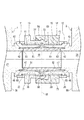
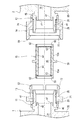
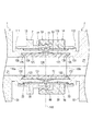
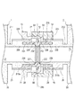
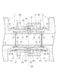
図1は、本発明の第1実施形態に係る流体機器の接続構造の断面図である。図2は、図1の部分拡大図である。図3は、図1の流体機器の接続構造における2台の流体機器1・2の離反状態を示す図である。図4は、図1の流体機器の接続構造における2台の流体機器1・2の接続途中の状態を示す図である。
FIG. 1 is a cross-sectional view of a connection structure of a fluid device according to a first embodiment of the present invention. FIG. 2 is a partially enlarged view of FIG. FIG. 3 is a diagram showing a separated state of the two fluid devices 1 and 2 in the connection structure of the fluid devices of FIG. FIG. 4 is a diagram showing a state in which the two fluid devices 1 and 2 are in the process of being connected in the connection structure of the fluid devices of FIG.
図1〜図4に示すように、本実施形態に係る流体機器の接続構造は、第1流体機器1と第2流体機器2とを流体的に接続するために用いられる。換言すれば、流体機器の接続構造は、第1流体機器1と第2流体機器2とが接続されることにより、内部に流体を流すことができるものである。
As shown in FIGS. 1 to 4, the fluid device connection structure according to the present embodiment is used to fluidly connect the first fluid device 1 and the second fluid device 2. In other words, the connection structure of the fluid device is such that the fluid can flow inside by connecting the first fluid device 1 and the second fluid device 2.
第1流体機器1および第2流体機器2は、互いに近接した状態で並置され得る形状を有する。第1流体機器1および第2流体機器2の各々の具体例としては、所定の流体流路を有するバルブ、流量計、ポンプおよび継手が挙げられるが、これに限定されるものではない。
The first fluid device 1 and the second fluid device 2 have a shape that can be juxtaposed in close proximity to each other. Specific examples of each of the first fluid device 1 and the second fluid device 2 include, but are not limited to, valves, flow meters, pumps and joints having a predetermined fluid flow path.
前記流体機器の接続構造は、第1受口部11と、第2受口部12と、第1筒状部材13と、第2筒状部材14と、接続体15とを備える。
The connection structure of the fluid device includes a first receiving portion 11, a second receiving portion 12, a first tubular member 13, a second tubular member 14, and a connecting body 15.
第1受口部11は、第1流体機器1に設けられる。第1受口部11は、第1流体機器1の第1流体流路21に接続される。第1受口部11は、筒状に形成される。
The first receiving portion 11 is provided in the first fluid device 1. The first receiving portion 11 is connected to the first fluid flow path 21 of the first fluid device 1. The first receiving portion 11 is formed in a tubular shape.
第2受口部12は、第2流体機器2に設けられる。第2受口部12は、第2流体機器2の第2流体流路25に接続される。第2受口部12は、筒状に形成される。
The second receiving portion 12 is provided in the second fluid device 2. The second receiving portion 12 is connected to the second fluid flow path 25 of the second fluid device 2. The second receiving portion 12 is formed in a tubular shape.
第1筒状部材13は、第1係合部53を有する。第1筒状部材13は、第1受口部11に設けられる。
The first tubular member 13 has a first engaging portion 53. The first tubular member 13 is provided in the first receiving portion 11.
第2筒状部材14は、第1係合部53と係合可能な第2係合部54を有する。第2筒状部材14は、第2受口部12に設けられる。
The second tubular member 14 has a second engaging portion 54 that can be engaged with the first engaging portion 53. The second tubular member 14 is provided in the second receiving portion 12.
接続体15は、第1受口部11と第2受口部12との間に設けられる。接続体15は、第1受口部11との間をシールし、かつ、第2受口部12との間をシールするように構成されている。
The connecting body 15 is provided between the first receiving portion 11 and the second receiving portion 12. The connecting body 15 is configured to seal between the first receiving portion 11 and the second receiving portion 12.
そして、前記流体機器の接続構造において、第2係合部54と第1係合部53との係合により、第2筒状部材14と第1筒状部材13とが固定される。
Then, in the connection structure of the fluid device, the second tubular member 14 and the first tubular member 13 are fixed by the engagement between the second engaging portion 54 and the first engaging portion 53.
本実施形態において、前記流体機器の接続構造に係る2台の流体機器1・2は、それぞれの受口部11・12が互いに軸方向に対向した状態で設置される。
In the present embodiment, the two fluid devices 1 and 2 related to the connection structure of the fluid devices are installed with their respective receiving portions 11 and 12 facing each other in the axial direction.
第1受口部11は、第1流体機器1に適用されるものである。第1受口部11は、本実施形態においては第1流体機器1のケーシング35と一体化されたものである。なお、第1受口部11は、ケーシング35と一体に形成されている必要はなく、別体としてもよい。
The first receiving portion 11 is applied to the first fluid device 1. In the present embodiment, the first receiving portion 11 is integrated with the casing 35 of the first fluid device 1. The first receiving portion 11 does not have to be integrally formed with the casing 35, and may be a separate body.
第1受口部11は、外筒部41と、内筒部42とを有する。外筒部41は、概ね一定の内径を有する円筒体からなり、ケーシング35における第1流体流路21の開口部周囲近傍にケーシング35の外部へ突出するように設けられる。
The first receiving portion 11 has an outer cylinder portion 41 and an inner cylinder portion 42. The outer cylinder portion 41 is made of a cylindrical body having a substantially constant inner diameter, and is provided so as to project to the outside of the casing 35 in the vicinity of the vicinity of the opening of the first fluid flow path 21 in the casing 35.
外筒部41は、その突出端部(軸方向一方の端部)43側から接続体15の一部を嵌め込むことができるように形成される。外筒部41は、その径方向において、嵌込後の接続体15の一部に対して略隙間なく配置される。
The outer cylinder portion 41 is formed so that a part of the connecting body 15 can be fitted from the protruding end portion (one end in the axial direction) 43 side. The outer cylinder portion 41 is arranged with substantially no gap with respect to a part of the connected body 15 after fitting in the radial direction thereof.
また、外筒部41は、第1ネジ23を含む。第1ネジ23は、外筒部41の外周に、第1ネジ23が外筒部41の軸方向に沿って設けられる。第1ネジ23は、雄ネジから構成される。
Further, the outer cylinder portion 41 includes the first screw 23. The first screw 23 is provided on the outer periphery of the outer cylinder portion 41 with the first screw 23 along the axial direction of the outer cylinder portion 41. The first screw 23 is composed of a male screw.
内筒部42は、外筒部41の内径よりも小さく、概ね一定の外径を有する円筒体からなり、ケーシング35における第1流体流路21の開口部周囲近傍に外筒部41の突出方向(第1受口部11の軸方向一方)と同方向へ突出するように設けられる。内筒部42は、外筒部41の径方向内方に所定間隔を隔てて配置されるとともに、外筒部41との関係において軸方向に伸びている。
The inner cylinder portion 42 is formed of a cylindrical body that is smaller than the inner diameter of the outer cylinder portion 41 and has a substantially constant outer diameter, and the outer cylinder portion 41 protrudes in the vicinity of the vicinity of the opening of the first fluid flow path 21 in the casing 35. It is provided so as to project in the same direction as (one of the axial directions of the first receiving portion 11). The inner cylinder portion 42 is arranged inward in the radial direction of the outer cylinder portion 41 at predetermined intervals, and extends in the axial direction in relation to the outer cylinder portion 41.
ここで、内筒部42は、その突出端部44が外筒部41の突出端部43よりも突出方向に対して反対側に位置するように、即ちケーシング35から外筒部41よりも突出しないように設けられる。こうして、第1受口部11が、外筒部41の軸方向(第1受口部11の軸方向)において外筒部41の軸方向他方側(ケーシング35側)で二重筒状を呈するように形成される。
Here, the inner cylinder portion 42 protrudes from the casing 35 from the outer cylinder portion 41 so that the protruding end portion 44 is located on the opposite side of the protruding end portion 43 of the outer cylinder portion 41 with respect to the protruding direction. It is provided so as not to. In this way, the first receiving portion 11 exhibits a double tubular shape in the axial direction of the outer cylinder portion 41 (axial direction of the first receiving portion 11) on the other side (casing 35 side) of the outer cylinder portion 41 in the axial direction. Is formed like this.
内筒部42は、第1流体流路21の流路径と略同一の内径を有し、かつ、接続体15の内径と略同一の内径を有する。内筒部42は、第1受口部11により第1流体機器1と接続体15とを流体的に接続させるべく、第1流体流路21と接続体15の内部空間48とを連通させるように第1流体機器1と接続体15との間に配置される。
The inner cylinder portion 42 has substantially the same inner diameter as the flow path diameter of the first fluid flow path 21, and has substantially the same inner diameter as the inner diameter of the connecting body 15. The inner cylinder portion 42 communicates the first fluid flow path 21 with the internal space 48 of the connecting body 15 so that the first fluid device 1 and the connecting body 15 are fluidly connected by the first receiving portion 11. Is arranged between the first fluid device 1 and the connecting body 15.
内筒部42の外周面と、これに対向する外筒部41の内周面との間には、環状の溝部46が形成される。溝部46は、外筒部41および内筒部42の突出方向(第2受口部12側)へ開口しかつ全周にわたって形成される。また、内筒部42の突出端部44近傍には、傾斜面47が形成される。傾斜面47は、第1流体流路21側から内筒部42の突出端部44側へ向かって径が漸次拡大するように形成される。
An annular groove 46 is formed between the outer peripheral surface of the inner cylinder portion 42 and the inner peripheral surface of the outer cylinder portion 41 facing the outer peripheral surface. The groove portion 46 is formed so as to open in the projecting direction (second receiving portion 12 side) of the outer cylinder portion 41 and the inner cylinder portion 42 and over the entire circumference. Further, an inclined surface 47 is formed in the vicinity of the protruding end portion 44 of the inner cylinder portion 42. The inclined surface 47 is formed so that the diameter gradually increases from the first fluid flow path 21 side toward the protruding end portion 44 side of the inner cylinder portion 42.
本実施形態において、第1受口部11は、所定の樹脂、例えば、PFA(テトラフルオロエチレン・パーフルオロアルキルビニルエーテル共重合体)、PVDF(ポリビニリデンフルオライド)、ETFE(テトラフルオロエチレン・エチレン共重合体)、FEP(テトラフルオロエチレン・ヘキサフルオロプロピレン共重合体)またはPTFE(ポリテトラフルオロエチレン)等のフッ素樹脂により製造される。なお、フッ素樹脂に限定されず、ポロプロピレン(PP)等のその他の樹脂であってもよい。
In the present embodiment, the first receiving portion 11 is formed of a predetermined resin, for example, PFA (tetrafluoroethylene / perfluoroalkyl vinyl ether copolymer), PVDF (polyvinylidene fluoride), ETFE (tetrafluoroethylene / ethylene). It is produced from a fluororesin such as polymer), FEP (tetrafluoroethylene / hexafluoropropylene copolymer) or PTFE (polytetrafluoroethylene). The resin is not limited to fluororesin, and may be other resin such as polypropylene (PP).
本実施形態において、第2受口部12は、第1受口部11を仮想中央面68に沿って反転させた形状であって、第1受口部11と実質的に同じ形状を有し、第2流体機器2のケーシング55に設けられる。そのため、第2受口部12については、第1受口部11の構成要素と略同じ構成要素には同じ符号を付して、その説明を省略する。なお、説明の便宜上、第1ネジ23および第2ネジ26のように実質的に同じ構成要素であっても異なる符号を付していることもある。
In the present embodiment, the second receiving portion 12 has a shape in which the first receiving portion 11 is inverted along the virtual central surface 68, and has substantially the same shape as the first receiving portion 11. , Is provided in the casing 55 of the second fluid device 2. Therefore, with respect to the second receiving portion 12, substantially the same components as the constituent elements of the first receiving portion 11 are designated by the same reference numerals, and the description thereof will be omitted. For convenience of explanation, even substantially the same components such as the first screw 23 and the second screw 26 may have different reference numerals.
接続体15は、第1シール部31と、第2シール部32とを有する。ここで、第1シール部31は、接続体15と第1受口部11との間をシールするものである。第2シール部32は、接続体15と第2受口部12との間をシールするものである。
The connecting body 15 has a first seal portion 31 and a second seal portion 32. Here, the first seal portion 31 seals between the connecting body 15 and the first receiving portion 11. The second sealing portion 32 seals between the connecting body 15 and the second receiving portion 12.
詳しくは、接続体15は、筒状に形成される。接続体15は、第1受口部11に対応する第1の部分15aと、第2受口部12に対応する第2の部分15bとを有する(図2参照)。第1の部分15aは、概ね一定の内径を有する円筒体からなり、接続体15の内部空間48の一部からなる流体流路を備える。第1の部分15aの流体流路は、第1流体流路21と連通するように、外筒部41に嵌め込まれた状態で第1受口部11に装着される。
Specifically, the connecting body 15 is formed in a tubular shape. The connecting body 15 has a first portion 15a corresponding to the first receiving portion 11 and a second portion 15b corresponding to the second receiving portion 12 (see FIG. 2). The first portion 15a is composed of a cylindrical body having a substantially constant inner diameter, and includes a fluid flow path formed of a part of the internal space 48 of the connecting body 15. The fluid flow path of the first portion 15a is mounted on the first receiving portion 11 in a state of being fitted in the outer cylinder portion 41 so as to communicate with the first fluid flow path 21.
第1の部分15aには、嵌合部61と、突部62と、突起63とが含まれる。嵌合部61は、円筒状に形成される。嵌合部61は、第1の部分15aが第1受口部11に装着された際、外筒部41を全周にわたって径方向内側から包囲した状態で嵌合される。そして、嵌合部61の軸方向両端部のうちの一方の端部(第1流体機器1側)には、突部62および突起63がそれぞれ形成される。
The first portion 15a includes a fitting portion 61, a protrusion 62, and a protrusion 63. The fitting portion 61 is formed in a cylindrical shape. When the first portion 15a is attached to the first receiving portion 11, the fitting portion 61 is fitted in a state of surrounding the outer cylinder portion 41 from the inside in the radial direction over the entire circumference. Then, a protrusion 62 and a protrusion 63 are formed at one end (on the side of the first fluid device 1) of both ends in the axial direction of the fitting portion 61, respectively.
突部62および突起63は、それぞれ円環状に形成される。突部62は、第1の部分15aが第1受口部11に装着された際に、第1受口部11の溝部46に対して全周にわたって圧入される。また、突部62は、第1受口部11に形成された溝部46の第1流体機器1側の側面に接触しない状態で挿通される。
The protrusion 62 and the protrusion 63 are each formed in an annular shape. When the first portion 15a is attached to the first receiving portion 11, the protrusion 62 is press-fitted into the groove portion 46 of the first receiving portion 11 over the entire circumference. Further, the protrusion 62 is inserted without contacting the side surface of the groove 46 formed in the first receiving portion 11 on the first fluid device 1 side.
突起63には、仮想中央面68側から第1流体機器1側に向かって漸次縮小するテーパ面65が形成される。テーパ面65は、第1の部分15aの径方向において、突部62の内方に配置される。テーパ面65は、第1の部分15aの軸方向において、内筒部42の傾斜面47に対向して配置される。テーパ面65は、第1の部分15aが第1受口部11に装着された際に内筒部42の傾斜面47に圧接される。
The protrusion 63 is formed with a tapered surface 65 that gradually shrinks from the virtual central surface 68 side toward the first fluid device 1 side. The tapered surface 65 is arranged inward of the protrusion 62 in the radial direction of the first portion 15a. The tapered surface 65 is arranged so as to face the inclined surface 47 of the inner cylinder portion 42 in the axial direction of the first portion 15a. The tapered surface 65 is pressed against the inclined surface 47 of the inner cylinder portion 42 when the first portion 15a is attached to the first receiving portion 11.
本実施形態において、接続体15は、その軸方向と直交しかつ当該軸方向における接続体15の中央に位置する仮想中央面68に対して対称な形状を有する。 すなわち、第1の部分15aおよび第2の部分15bが実質的に同じ形状を有する。そのため、第2の部分15bについては、図中で第1の部分15aの構成要素と略同じ構成要素に同一符号を付して、その説明を省略する。
In the present embodiment, the connecting body 15 has a shape orthogonal to the axial direction thereof and symmetrical with respect to the virtual central surface 68 located at the center of the connecting body 15 in the axial direction. That is, the first portion 15a and the second portion 15b have substantially the same shape. Therefore, with respect to the second portion 15b, substantially the same components as those of the first portion 15a in the drawing are designated by the same reference numerals, and the description thereof will be omitted.
本実施形態において、接続体15は、所定の樹脂、例えば、PFA、PVDF、ETFE、FEPまたはPTFE等のフッ素樹脂やその他の熱可塑性樹脂により製造される。
In this embodiment, the connector 15 is made of a predetermined resin, for example, a fluororesin such as PFA, PVDF, ETFE, FEP or PTFE or other thermoplastic resin.
なお、接続体15は、本実施形態においては実質的に同じ形状を有する第1の部分15aおよび第2の部分15bを一体化したものとしているが、これに代えて、互いに異なる形状を有する第1の部分および第2の部分を連結したものとしてもよい。
In the present embodiment, the connecting body 15 integrates the first portion 15a and the second portion 15b having substantially the same shape, but instead, the connecting body 15 has a different shape from each other. The first part and the second part may be connected.
本実施形態において、第1筒状部材13は、第1受口部11、詳しくはその外筒部41を包囲し得るように構成される。第1筒状部材13は、第1係合部53に加え、第1ネジ23に螺合された第3ネジ28を更に有する。第3ネジ28は、第1筒状部材13の内周に形成される。
In the present embodiment, the first tubular member 13 is configured to be able to surround the first receiving portion 11, specifically the outer tubular portion 41 thereof. The first tubular member 13 further has a third screw 28 screwed into the first screw 23 in addition to the first engaging portion 53. The third screw 28 is formed on the inner circumference of the first tubular member 13.
第2筒状部材14は、第2受口部12、詳しくはその外筒部41を包囲するように構成される。第2筒状部材14は、第2係合部54に加え、第2ネジ26に螺合された第4ネジ29を更に有する。第4ネジ29は、第2筒状部材14の内周に形成される。
The second tubular member 14 is configured to surround the second receiving portion 12, specifically the outer tubular portion 41 thereof. The second tubular member 14 further has a fourth screw 29 screwed into the second screw 26 in addition to the second engaging portion 54. The fourth screw 29 is formed on the inner circumference of the second tubular member 14.
詳しくは、第1筒状部材13は、第1係合部53のほか、第1本体部71を有する。
Specifically, the first tubular member 13 has a first main body portion 71 in addition to the first engaging portion 53.
第1本体部71は、第1受口部11に外嵌された状態で固定される。第1本体部71は、筒状に形成される。第1本体部71の内周に、第3ネジ28が設けられる。
The first main body portion 71 is fixed in a state of being fitted onto the first receiving portion 11. The first main body 71 is formed in a tubular shape. A third screw 28 is provided on the inner circumference of the first main body 71.
第1本体部71は、第3ネジ28が第1ネジ23に螺合した状態で、第1受口部11の外筒部41をその全周にわたって包囲するように第1受口部11に取り付けられる。第1本体部71は、第1筒状部材13の軸方向に延在するように設けられる。第1本体部71は、第1筒状部材13においてその軸方向他方側(第1流体機器1側)に配置される。
The first main body portion 71 is attached to the first socket portion 11 so as to surround the outer cylinder portion 41 of the first socket portion 11 over the entire circumference in a state where the third screw 28 is screwed into the first screw 23. It is attached. The first main body 71 is provided so as to extend in the axial direction of the first tubular member 13. The first main body 71 is arranged on the other side (first fluid device 1 side) in the axial direction of the first tubular member 13.
また、第1係合部53には、第1係合爪72が設けられる。第1係合爪72は、第1筒状部材13の軸方向へ突出し、かつ第1本体部71に対してその径方向へ撓み得るように、第1本体部71に設けられる。
Further, the first engaging portion 53 is provided with a first engaging claw 72. The first engaging claw 72 is provided on the first main body 71 so that the first tubular member 13 projects in the axial direction and can bend in the radial direction with respect to the first main body 71.
第1係合部53の第1係合爪72は、第1筒状部材13においてその軸方向一方側(第1流体機器1と反対側)に配置される。第1係合爪72は、第1本体部71の一方の端部から第1筒状部材13の軸方向一方である第2流体機器2側へ突出するように形成される。第1係合爪72は、その突出端部(先端部)側に第1鉤状部分73を備える。
The first engaging claw 72 of the first engaging portion 53 is arranged on one side (opposite side of the first fluid device 1) in the axial direction of the first tubular member 13. The first engaging claw 72 is formed so as to project from one end of the first main body 71 toward the second fluid device 2 which is one axial direction of the first tubular member 13. The first engaging claw 72 includes a first hook-shaped portion 73 on the protruding end (tip) side thereof.
第1係合爪72は、第1筒状部材13に一つまたは複数設けられる。第1係合爪72は、第1筒状部材13に一つ設けられる場合であれば、可撓性を確保するために周方向の一部が切り欠かれた筒状(C字状等)に形成され、第1本体部71と同軸上に配置される。第1係合爪72は、第1筒状部材13に複数設けられる場合であれば、第1本体部71に対してその周方向に所定間隔ごとに配置される。
One or a plurality of first engaging claws 72 are provided on the first tubular member 13. If one of the first engaging claws 72 is provided on the first tubular member 13, it has a tubular shape (C-shaped or the like) in which a part in the circumferential direction is cut out in order to ensure flexibility. It is formed in the above and is arranged coaxially with the first main body 71. If a plurality of first engaging claws 72 are provided on the first tubular member 13, they are arranged at predetermined intervals in the circumferential direction with respect to the first main body portion 71.
第1鉤状部分73には、テーパ部74が含まれる。テーパ部74は、その径が第1流体機器1のケーシング35側から第1筒状部材13の軸方向一方である第2流体機器2へ向かって漸次縮小するように形成される。第1係合爪72は、所定以上の外力が第1係合爪72に加えられたときに、第1本体部71に対して第1筒状部材13の径方向内方へ一時的に撓むことができるように可撓性を有する。
The first hook-shaped portion 73 includes a tapered portion 74. The tapered portion 74 is formed so that its diameter gradually decreases from the casing 35 side of the first fluid device 1 toward the second fluid device 2, which is one of the axial directions of the first tubular member 13. The first engaging claw 72 temporarily bends inward in the radial direction of the first tubular member 13 with respect to the first main body 71 when an external force equal to or greater than a predetermined value is applied to the first engaging claw 72. It is flexible so that it can be removed.
また、第2筒状部材14は、第2係合部54のほか、第2本体部76を有する。
Further, the second tubular member 14 has a second main body portion 76 in addition to the second engaging portion 54.
第2本体部76は、第2受口部12に外嵌された状態で固定される。第2本体部76は、筒状に形成される。第2本体部76の内周には、第4ネジ29が設けられる。
The second main body portion 76 is fixed in a state of being fitted onto the second receiving portion 12. The second main body portion 76 is formed in a tubular shape. A fourth screw 29 is provided on the inner circumference of the second main body 76.
第2本体部76は、第4ネジ29が第2ネジ26に螺合された状態で、第2受口部12の外筒部41をその全周にわたって包囲するように第2受口部12に取り付けられる。第2本体部76は、第2筒状部材14の軸方向に延在し、第2筒状部材14においてその軸方向他方側(第2流体機器2側)に配置される。
The second main body portion 76 has a second socket portion 12 so as to surround the outer cylinder portion 41 of the second socket portion 12 over the entire circumference in a state where the fourth screw 29 is screwed into the second screw 26. Attached to. The second main body portion 76 extends in the axial direction of the second tubular member 14, and is arranged on the other side (second fluid device 2 side) of the second tubular member 14 in the axial direction.
また、第2係合部54は、第1係合爪71と係合可能な第2係合爪77を備える。第2係合爪77は、第2筒状部材14の軸方向へ突出するように、第2本体部76に設けられる。
Further, the second engaging portion 54 includes a second engaging claw 77 that can be engaged with the first engaging claw 71. The second engaging claw 77 is provided on the second main body portion 76 so as to project in the axial direction of the second tubular member 14.
第2係合部54の第2係合爪77は、第2筒状部材14においてその軸方向他方側(第2流体機器2の反対側)に配置される。第2係合爪77は、第2本体部76の軸方向において、第2本体部76の一方の端部から第2筒状部材14の軸方向他方である第1流体機器1側へ突出するように形成される。第2係合爪77は、その突出端部(先端部)側に第2鉤状部分78を備える。
The second engaging claw 77 of the second engaging portion 54 is arranged on the other side in the axial direction (opposite side of the second fluid device 2) of the second tubular member 14. The second engaging claw 77 projects from one end of the second main body 76 toward the first fluid device 1 side, which is the other axial direction of the second tubular member 14, in the axial direction of the second main body 76. Is formed as follows. The second engaging claw 77 includes a second hook-shaped portion 78 on the protruding end (tip) side thereof.
第2係合爪77は、第2筒状部材14に一つまたは複数設けられる。第2係合爪77は、第2筒状部材14に一つ設けられる場合であれば、可撓性を確保するために周方向の一部が切り欠かれた筒状(C字状等)に形成され、第2本体部76と同軸上に配置される。第2係合爪77は、第2筒状部材14に複数設けられる場合であれば、第2本体部76に対してその周方向に所定間隔ごとに配置される。
One or more of the second engaging claws 77 are provided on the second tubular member 14. If one of the second engaging claws 77 is provided on the second tubular member 14, the second engaging claw 77 has a tubular shape (C-shaped or the like) in which a part in the circumferential direction is cut out in order to ensure flexibility. It is formed in the above and is arranged coaxially with the second main body portion 76. If a plurality of second engaging claws 77 are provided on the second tubular member 14, they are arranged at predetermined intervals in the circumferential direction with respect to the second main body portion 76.
第2鉤状部分78には、テーパ部79が含まれる。テーパ部79は、その径が第2筒状部材14の軸方向他方である第2流体機器2側から第2筒状部材14の軸方向一方である第1流体機器1側へ向かって漸次縮小するように形成される。第2係合爪77は、第1係合爪72を第1流体機器1側から包囲し、第2本体部76の内径よりも大きい内径を有する。
The second hook-shaped portion 78 includes a tapered portion 79. The tapered portion 79 gradually shrinks from the second fluid device 2 side whose diameter is the other axial direction of the second tubular member 14 toward the first fluid device 1 side whose diameter is the other axial direction of the second tubular member 14. Is formed to do. The second engaging claw 77 surrounds the first engaging claw 72 from the side of the first fluid device 1 and has an inner diameter larger than the inner diameter of the second main body portion 76.
なお、第2係合部54は、第2係合爪77に代えて、第1係合爪72と係合可能な爪受け(第1係合爪72と係合可能な凹部を含むもの)を備えていてもよい。また、第2係合部54は、第1筒状部材13の第1本体部71に係合可能な形状としても良い。
The second engaging portion 54 replaces the second engaging claw 77 with a claw receiver that can engage with the first engaging claw 72 (including a recess that can engage with the first engaging claw 72). May be provided. Further, the second engaging portion 54 may have a shape capable of engaging with the first main body portion 71 of the first tubular member 13.
このような第1筒状部材13と第2筒状部材14とは、第1係合爪72と第2係合爪77とが対向した状態で、互いに嵌め合わされる。この際、第1筒状部材13は、第2筒状部材14と同軸上に配置される。第1筒状部材13は、その軸方向において第1鉤状部分73が第2鉤状部分78と軸方向に対向するように、第2筒状部材14の径方向内方に配置される。
Such a first tubular member 13 and a second tubular member 14 are fitted to each other with the first engaging claw 72 and the second engaging claw 77 facing each other. At this time, the first tubular member 13 is arranged coaxially with the second tubular member 14. The first tubular member 13 is arranged radially inward of the second tubular member 14 so that the first hook-shaped portion 73 faces the second hook-shaped portion 78 in the axial direction in the axial direction thereof.
こうして、第1係合爪72と第2係合爪77とは、互いに嵌め合わされた状態において、第1筒状部材13と第2筒状部材14とが離反することを規制するように係合される。具体的には、第1係合爪72と第2係合爪77とは、第1鉤状部分73と第2鉤状部分78とが互いに引っ掛かることにより、第1筒状部材13および第2筒状部材14の軸方向に係合される。
In this way, the first engaging claw 72 and the second engaging claw 77 are engaged so as to prevent the first tubular member 13 and the second tubular member 14 from being separated from each other in a state of being fitted to each other. Will be done. Specifically, the first engaging claw 72 and the second engaging claw 77 are the first tubular member 13 and the second engaging claw 77 because the first hook-shaped portion 73 and the second hook-shaped portion 78 are caught by each other. The tubular member 14 is engaged in the axial direction.
なお、第1筒状部材13および第2筒状部材14は、接続体15における各突部62を対応する溝部46に圧入し、かつ接続体15における各突起63のテーパ面65を対応する内筒部42の突出端部44の傾斜面47に圧接するように、第1係合爪72と第2係合爪77とを係合させる構成とされる。
The first tubular member 13 and the second tubular member 14 press-fit each protrusion 62 of the connecting body 15 into the corresponding groove portion 46, and correspond to the tapered surface 65 of each protrusion 63 of the connecting body 15. The first engaging claw 72 and the second engaging claw 77 are engaged with each other so as to be in pressure contact with the inclined surface 47 of the protruding end portion 44 of the tubular portion 42.
本実施形態において、第1筒状部材13は、所定の樹脂、例えば、PFA、PVDF、ETFE、FEPまたはPTFE等のフッ素樹脂により製造される。また、第2筒状部材14は、第1筒状部材13と同様に、所定の樹脂、例えば、PFA、PVDF、ETFE、FEPまたはPTFE等のフッ素樹脂により製造される。
In the present embodiment, the first tubular member 13 is manufactured from a predetermined resin, for example, a fluororesin such as PFA, PVDF, ETFE, FEP or PTFE. Further, the second tubular member 14 is manufactured of a predetermined resin, for example, a fluororesin such as PFA, PVDF, ETFE, FEP or PTFE, like the first tubular member 13.
ここで、第1流体機器1と第2流体機器2との接続に際しては、まず、図3に示すように、第3ネジ28を第1ネジ23に螺合して、第1受口部11に第1筒状部材13を着脱可能に固定する。また、第4ネジ29を第2ネジ26に螺合して、第2受口部12に第2筒状部材14を着脱可能に固定する。そして、第1受口部11および第2受口部12のいずれか一方に接続体15を挿入する。そして、図4に示すように、互いに離反状態にある第1流体機器1と第2流体機器2とを対向させて、接続体15を第1受口部13および第2受口部14の他方に近づける。接続体15を第1受口部13および第2受口部14の他方に挿入しつつ、第1筒状部材13と第2筒状部材14とを近づける。その後、第1筒状部材13の第1係合爪72を第1筒状部材13の径方向内方へ一時的に撓ませることにより第1筒状部材13を第2筒状部材14に嵌め込み、その後に第1係合爪72を第2係合爪77に係合させる。こうして、第1筒状部材13と第2筒状部材14とを、それらの軸方向のうち互いに離間する方向に相対移動しないように固定する。
Here, when connecting the first fluid device 1 and the second fluid device 2, first, as shown in FIG. 3, the third screw 28 is screwed into the first screw 23, and the first receiving portion 11 The first tubular member 13 is detachably fixed to the surface. Further, the fourth screw 29 is screwed into the second screw 26 to detachably fix the second tubular member 14 to the second receiving portion 12. Then, the connecting body 15 is inserted into either the first receiving portion 11 or the second receiving portion 12. Then, as shown in FIG. 4, the first fluid device 1 and the second fluid device 2 that are separated from each other are opposed to each other, and the connecting body 15 is connected to the other of the first receiving portion 13 and the second receiving portion 14. Get closer to. While inserting the connecting body 15 into the other of the first receiving portion 13 and the second receiving portion 14, the first tubular member 13 and the second tubular member 14 are brought close to each other. After that, the first engaging claw 72 of the first tubular member 13 is temporarily bent inward in the radial direction of the first tubular member 13 to fit the first tubular member 13 into the second tubular member 14. After that, the first engaging claw 72 is engaged with the second engaging claw 77. In this way, the first tubular member 13 and the second tubular member 14 are fixed so as not to move relative to each other in the axial direction thereof.
第1筒状部材13と第2筒状部材14との固定により、第1受口部11と第2受口部12とが離間する方向に移動することが阻止されることとなり、第1流体機器1と第2流体機器2とが流体的に接続された状態、即ち第1流体流路21と第2流体流路25とが接続体15の内部空間48を介して連通された状態が保持される。
By fixing the first tubular member 13 and the second tubular member 14, the first receiving portion 11 and the second receiving portion 12 are prevented from moving in a direction in which they are separated from each other, and the first fluid The state in which the device 1 and the second fluid device 2 are fluidly connected, that is, the state in which the first fluid flow path 21 and the second fluid flow path 25 are communicated with each other via the internal space 48 of the connecting body 15 is maintained. Will be done.
また、第1係合爪72と第2係合爪77との係合に伴って、第1シール部31および第2シール部32によるシールが形成される。すなわち、接続体15における各突部62が対応する溝部46に圧入されるとともに、接続体15における各突起63のテーパ面65が対応する内筒部42の突出端部44の傾斜面47に圧接させられる。
Further, with the engagement between the first engaging claw 72 and the second engaging claw 77, a seal is formed by the first sealing portion 31 and the second sealing portion 32. That is, each protrusion 62 of the connecting body 15 is press-fitted into the corresponding groove portion 46, and the tapered surface 65 of each protrusion 63 of the connecting body 15 is press-fitted to the inclined surface 47 of the corresponding protruding end portion 44 of the inner cylinder portion 42. Be made to.
ここで、第1シール部31と第2シール部32とによれば、シール力が軸方向に作用する一次シール領域81と、シール力が径方向に作用する二次シール領域82とが形成される。なお、第1筒状部材13の第1係合爪72が第2筒状部材14の第2係合爪77に嵌め込まれるときには、作業者による手作業、または、作業者による手作業に加え所定の工具等の嵌込手段が用いられる。
Here, according to the first seal portion 31 and the second seal portion 32, a primary seal region 81 in which the seal force acts in the axial direction and a secondary seal region 82 in which the seal force acts in the radial direction are formed. NS. When the first engaging claw 72 of the first tubular member 13 is fitted into the second engaging claw 77 of the second tubular member 14, it is predetermined in addition to the manual work by the operator or the manual work by the operator. A fitting means such as a tool of the above is used.
したがって、本実施形態に係る流体機器の接続構造によれば、2台の流体機器1・2の接続部からの流体の漏洩を防止することができる。また、第1流体機器1と第2流体機器2とを流体的に接続するために、第1流体機器1と第2流体機器2との間にチューブ等の部材を介在させる必要がない。よって、2台の流体機器1・2をできるだけ近接させた状態で流体的に接続して、これらの流体機器1・2の設置スペースの省スペース化を図ることができる。
Therefore, according to the fluid device connection structure according to the present embodiment, it is possible to prevent fluid leakage from the connection portion of the two fluid devices 1 and 2. Further, in order to fluidly connect the first fluid device 1 and the second fluid device 2, it is not necessary to interpose a member such as a tube between the first fluid device 1 and the second fluid device 2. Therefore, the two fluid devices 1 and 2 can be fluidly connected in a state of being as close as possible to each other, and the installation space of these fluid devices 1 and 2 can be saved.
また、本実施形態における接続体15は、張出部88を有する。張出部88は、第1流体機器1と第2流体機器2とが流体的に接続された状態において、第1受口部11と第2受口部12との間に配置される。
Further, the connecting body 15 in the present embodiment has an overhanging portion 88. The overhanging portion 88 is arranged between the first receiving portion 11 and the second receiving portion 12 in a state where the first fluid device 1 and the second fluid device 2 are fluidly connected.
張出部88は、第1受口部11と第2受口部12との間に非接触状態で挟まれる。張出部88は、接続体15の径方向外方へ張り出しており、環状に形成される。
The overhanging portion 88 is sandwiched between the first receiving portion 11 and the second receiving portion 12 in a non-contact state. The overhanging portion 88 projects outward in the radial direction of the connecting body 15 and is formed in an annular shape.
張出部88は、第1受口部11および第2受口部12の各々の突出端部43の外径よりも大きい外径を有する。張出部88は、接続体15における仮想中央面68上であって、接続体15の軸方向中途部(接続体15における第1の部分15aと第2の部分15bとの境界部)に設けられる。
The overhanging portion 88 has an outer diameter larger than the outer diameter of each of the protruding end portions 43 of the first receiving portion 11 and the second receiving portion 12. The overhanging portion 88 is provided on the virtual central surface 68 of the connecting body 15 and at an axially intermediate portion of the connecting body 15 (the boundary portion between the first portion 15a and the second portion 15b of the connecting body 15). Be done.
より詳しくは、張出部88は、接続体15が第1受口部11と第2受口部12とに装着される際に各々の突出端部43・43間に介在するように配置される。張出部88は、第1受口部11の突出端部43と軸方向に対向し、かつ、第1受口部11の突出端部43と軸方向に対向する。張出部88は、第1受口部11および第2受口部12から接続体15を取り外すことを容易にする。
More specifically, the overhanging portion 88 is arranged so as to intervene between the protruding end portions 43 and 43 when the connecting body 15 is attached to the first receiving portion 11 and the second receiving portion 12. NS. The overhanging portion 88 faces the protruding end portion 43 of the first receiving portion 11 in the axial direction and faces the protruding end portion 43 of the first receiving portion 11 in the axial direction. The overhanging portion 88 facilitates the removal of the connecting body 15 from the first receiving portion 11 and the second receiving portion 12.
以下、図5乃至図8を用いて、本発明の第2実施形態乃至第5実施形態について説明する。なお、図中、前述の第1実施形態に係る流体機器の接続構造の構成要素と実質的に同じ構成要素については、図中で同じ符号を付して、その説明を適宜省略する。
Hereinafter, the second to fifth embodiments of the present invention will be described with reference to FIGS. 5 to 8. In the drawings, the components substantially the same as the components of the connection structure of the fluid device according to the above-described first embodiment are designated by the same reference numerals in the drawings, and the description thereof will be omitted as appropriate.
図5は、本発明の第2実施形態に係る流体機器の接続構造の断面図である。同図に示すように、本実施形態に係る流体機器の接続構造は、第1受口部111と接続体115との間をシールする第1シール部121に関する構成、および、第2受口部112と接続体115との間をシールする第2シール部122に関する構成が、前述の第1実施形態に係る流体機器の接続構造と相違する。
FIG. 5 is a cross-sectional view of a connection structure of a fluid device according to a second embodiment of the present invention. As shown in the figure, the connection structure of the fluid device according to the present embodiment includes a configuration relating to a first seal portion 121 that seals between the first socket portion 111 and the connecting body 115, and a second socket portion. The configuration of the second seal portion 122 that seals between the 112 and the connecting body 115 is different from the connection structure of the fluid device according to the first embodiment described above.
第1受口部111は、第1流体機器1に適用されるものであり、本実施形態においては第1流体機器1のケーシング35と一体化されたものである。第1受口部111は、筒部125と、環状突起126とを有する。筒部125は、概ね一定の内径を有する円筒体からなり、ケーシング35における第1流体流路21の開口部周囲近傍にケーシング35の外部に向かって突出するように設けられる。
The first receiving portion 111 is applied to the first fluid device 1, and is integrated with the casing 35 of the first fluid device 1 in the present embodiment. The first receiving portion 111 has a tubular portion 125 and an annular protrusion 126. The tubular portion 125 is made of a cylindrical body having a substantially constant inner diameter, and is provided so as to project toward the outside of the casing 35 in the vicinity of the periphery of the opening of the first fluid flow path 21 in the casing 35.
筒部125は、その突出端部(軸方向一方の端部)側から接続体115の一部を嵌め込むことができるように形成される。筒部125は、嵌込後の接続体115の一部に対して、前記突出端部付近を除き略隙間なく配置される。また、筒部125の外周には、第1ネジ23が筒部125の軸方向に沿って形成される。第1ネジ23は、雄ネジから構成される。
The tubular portion 125 is formed so that a part of the connecting body 115 can be fitted from the protruding end portion (one end in the axial direction) side. The tubular portion 125 is arranged with respect to a part of the connecting body 115 after fitting, except in the vicinity of the protruding end portion, with substantially no gap. Further, a first screw 23 is formed on the outer circumference of the tubular portion 125 along the axial direction of the tubular portion 125. The first screw 23 is composed of a male screw.
環状突起126は、筒部125の内径よりも小さい外径を有するリング状体からなり、ケーシング35における第1流体流路21の開口部周囲近傍に筒部125の突出方向(筒部125の軸方向一方)と同方向へ突出するように設けられる。環状突起126は、筒部125の径方向内方に所定間隔を隔てて配置されるとともに、筒部125と同一方向に延長する。
The annular protrusion 126 is formed of a ring-shaped body having an outer diameter smaller than the inner diameter of the tubular portion 125, and the protrusion direction of the tubular portion 125 (the axis of the tubular portion 125) is formed in the vicinity of the periphery of the opening of the first fluid flow path 21 in the casing 35. It is provided so as to project in the same direction as (one of the directions). The annular protrusion 126 is arranged inward in the radial direction of the tubular portion 125 at a predetermined interval, and extends in the same direction as the tubular portion 125.
環状突起126は、第1流体流路21の流路径と略同一の内径を有し、かつ、接続体115の内径と略同一の内径を有する。環状突起126は、第1流体機器1と接続体115との間に配置され、第1流体流路21と接続体115の内部空間138とを連通させる。第1受口部111により第1流体機器1と接続体115とが流体的(流体が内部を流れることができるよう)に接続される。
The annular projection 126 has an inner diameter substantially the same as the flow path diameter of the first fluid flow path 21, and has an inner diameter substantially the same as the inner diameter of the connecting body 115. The annular projection 126 is arranged between the first fluid device 1 and the connecting body 115, and communicates the first fluid flow path 21 with the internal space 138 of the connecting body 115. The first fluid device 1 and the connecting body 115 are fluidly (so that the fluid can flow inside) are connected by the first receiving portion 111.
環状突起126の外周面には、テーパ面128が含まれる。テーパ面128は、その外径が環状突起126の突出方向(第1受口部111の軸方向一方)へ向かって軸方向に漸次縮小するように形成される。テーパ面128は、環状突起126の外周において全周にわたって延設され、当該テーパ面128と対向する筒部125の内周面とが所定間隔を隔てて配置される。
The outer peripheral surface of the annular projection 126 includes a tapered surface 128. The tapered surface 128 is formed so that its outer diameter gradually decreases in the axial direction toward the projecting direction of the annular projection 126 (one of the axial directions of the first receiving portion 111). The tapered surface 128 extends over the entire circumference of the annular projection 126, and the tapered surface 128 and the inner peripheral surface of the tubular portion 125 facing the tapered surface 128 are arranged at predetermined intervals.
第2受口部112は、本実施形態においては第1受口部111と実質的に同じ形状を有する。そのため、第2受口部112については、第1受口部111の構成要素と略同じ構成要素には同じ符号を付して、その説明を省略する。なお、説明の便宜上、第1ネジ23、第2ネジ26のように実質的に同じ構成要素であっても異なる符号を付していることもある。
The second receiving portion 112 has substantially the same shape as the first receiving portion 111 in the present embodiment. Therefore, with respect to the second receiving portion 112, substantially the same components as the constituent elements of the first receiving portion 111 are designated by the same reference numerals, and the description thereof will be omitted. For convenience of explanation, even substantially the same components such as the first screw 23 and the second screw 26 may have different reference numerals.
接続体115は、第1受口部111に対応する第1の部分115aと、第2受口部112に対応する第2の部分115bとを有する。第1の部分115aは、概ね一定の内径を有する円筒体からなり、流体流路を備える。この第1の部分115aの流体流路は、接続体115において第1の部分115aに対応する内部空間から形成される。第1の部分115aの流体流路は、第1流体流路21と連通するように、筒部125に嵌め込まれた状態で第1受口部111に装着される。
The connecting body 115 has a first portion 115a corresponding to the first receiving portion 111 and a second portion 115b corresponding to the second receiving portion 112. The first portion 115a is made of a cylindrical body having a substantially constant inner diameter, and includes a fluid flow path. The fluid flow path of the first portion 115a is formed from the internal space corresponding to the first portion 115a in the connecting body 115. The fluid flow path of the first portion 115a is mounted on the first receiving portion 111 in a state of being fitted in the tubular portion 125 so as to communicate with the first fluid flow path 21.
第1の部分115aには、嵌合部131と、突出部132とが含まれる。嵌合部131は、円筒状に形成される。嵌合部131は、第1の部分115aが第1受口部111に装着された際、筒部125に内嵌される。そして、第1の部分115aにおける嵌合部131の軸方向両端部のうちの一方の端部(嵌合部131の第1流体機器1側)には、突出部132が軸方向に突出するように形成される。
The first portion 115a includes a fitting portion 131 and a protruding portion 132. The fitting portion 131 is formed in a cylindrical shape. The fitting portion 131 is internally fitted into the tubular portion 125 when the first portion 115a is attached to the first receiving portion 111. Then, the protruding portion 132 projects in the axial direction to one end of the axially both ends of the fitting portion 131 in the first portion 115a (the first fluid device 1 side of the fitting portion 131). Is formed in.
突出部132は、円環状に形成される。突出部132は、第1の部分115aが第1受口部111に装着された際に、当該突出部132の内周側に形成された傾斜面135を環状突起126のテーパ面128に対して圧接させる。傾斜面135は、突出部132の突出方向(第1流体機器1側)へ向かって漸次拡大するように形成される。傾斜面135は、突出部132と対向し、突出部132の全周にわたって延設される。
The protrusion 132 is formed in an annular shape. When the first portion 115a is attached to the first receiving portion 111, the protruding portion 132 has an inclined surface 135 formed on the inner peripheral side of the protruding portion 132 with respect to the tapered surface 128 of the annular projection 126. Press contact. The inclined surface 135 is formed so as to gradually expand in the projecting direction (first fluid device 1 side) of the projecting portion 132. The inclined surface 135 faces the protruding portion 132 and extends over the entire circumference of the protruding portion 132.
本実施形態に係る接続体115は、その軸方向と直交しかつ当該軸方向において接続体115の中央に位置する仮想中央面148に対して対称な形状を有する。すなわち、第1の部分115aおよび第2の部分115bが実質的に同じ形状を有する。
The connecting body 115 according to the present embodiment has a shape orthogonal to the axial direction thereof and symmetrical with respect to the virtual central surface 148 located at the center of the connecting body 115 in the axial direction. That is, the first portion 115a and the second portion 115b have substantially the same shape.
このような流体機器の接続構造により、前述した第1実施形態に係る流体機器の接続構造と同様に、互いに流体的に接続された第1流体機器1および第2流体機器2の設置スペースの省スペース化を図ることができる。また、第1流体機器1と第2流体機器2との接続時、接続体115が、第1シール部121および第2シール部122を形成する。そして、接続体115の第1の部分115aの傾斜面135が、第1受口部111におけるテーパ面128に圧接され、第2の部分115bの傾斜面135が、第2受口部112におけるテーパ面128に圧接される。
With such a fluid device connection structure, the installation space of the first fluid device 1 and the second fluid device 2 that are fluidly connected to each other can be saved as in the fluid device connection structure according to the first embodiment described above. Space can be achieved. Further, when the first fluid device 1 and the second fluid device 2 are connected, the connecting body 115 forms the first seal portion 121 and the second seal portion 122. Then, the inclined surface 135 of the first portion 115a of the connecting body 115 is pressed against the tapered surface 128 of the first receiving portion 111, and the inclined surface 135 of the second portion 115b is tapered at the second receiving portion 112. It is pressed against the surface 128.
よって、第1流体機器1と第2流体機器2との接続部から流体が漏洩することを防止でき、第1流体機器1と第2流体機器2とを従来のチューブ等の部材を用いずに短距離で接続することが可能となる。
Therefore, it is possible to prevent fluid from leaking from the connection portion between the first fluid device 1 and the second fluid device 2, and the first fluid device 1 and the second fluid device 2 can be connected to each other without using a conventional member such as a tube. It is possible to connect in a short distance.
図6は、本発明の第3実施形態に係る流体機器の接続構造の断面図である。同図に示すように、本実施形態に係る流体機器の接続構造は、第1受口部151と接続体155との間をシールする第1シール部161に関する構成、および、第2受口部152と接続体155との間をシールする第2シール部162に関する構成が、前述の第1実施形態に係る流体機器の接続構造と相違する。
FIG. 6 is a cross-sectional view of a connection structure of a fluid device according to a third embodiment of the present invention. As shown in the figure, the connection structure of the fluid device according to the present embodiment includes a configuration relating to a first seal portion 161 that seals between the first socket portion 151 and the connecting body 155, and a second socket portion. The configuration of the second seal portion 162 that seals between the 152 and the connecting body 155 is different from the connection structure of the fluid device according to the first embodiment described above.
第1受口部151は、第1流体機器1に適用されるものであり、本実施形態においては第1流体機器1のケーシング35と一体化されたものである。第1受口部151の外周には、第1ネジ23が第1受口部151の軸方向に沿って形成される。第1ネジ23は、雄ネジから構成される。
The first receiving portion 151 is applied to the first fluid device 1, and is integrated with the casing 35 of the first fluid device 1 in the present embodiment. A first screw 23 is formed on the outer periphery of the first receiving portion 151 along the axial direction of the first receiving portion 151. The first screw 23 is composed of a male screw.
第1受口部151は、筒部165と、突出部166とを有する。筒部165は、段差を内周に有する円筒体からなり、ケーシング35から離れる方向に向かって突出するように設けられる。筒部165は、ケーシング35に形成される第1流体流路21の開口部近傍に設けられる。
The first receiving portion 151 has a tubular portion 165 and a protruding portion 166. The tubular portion 165 is formed of a cylindrical body having a step on the inner circumference, and is provided so as to project in a direction away from the casing 35. The tubular portion 165 is provided in the vicinity of the opening of the first fluid flow path 21 formed in the casing 35.
筒部165は、段差部167よりも軸方向一方側(第1受口部151の開口部側)に、第1筒状部分165aを有する。この第1筒状部分165aは、接続体155の一部を嵌め込むことができるように形成される。この第1筒状部分165aは、嵌込後の接続体155の一部に対して概ねの領域で隙間なく配置される。
The tubular portion 165 has a first tubular portion 165a on one side in the axial direction (the opening side of the first receiving portion 151) with respect to the step portion 167. The first tubular portion 165a is formed so that a part of the connecting body 155 can be fitted. The first tubular portion 165a is arranged without a gap in a general area with respect to a part of the connecting body 155 after fitting.
筒部165は、段差部167よりも軸方向他方側(第1流体機器1側)に、第2筒状部分165bを有する。この第2筒状部分165bは、第1流体流路21の流路径と略同一の内径を有し、かつ、接続体115の内径と略同一の内径を有する。第2筒状部分165bは、第1受口部151により第1流体機器1と接続体155とを流体的に接続させるべく、第1流体流路21と接続体155の内部空間178とを連通させるように第1流体機器1と接続体155との間に配置される。
The tubular portion 165 has a second tubular portion 165b on the other side (first fluid device 1 side) in the axial direction from the step portion 167. The second tubular portion 165b has substantially the same inner diameter as the flow path diameter of the first fluid flow path 21, and has substantially the same inner diameter as the inner diameter of the connecting body 115. The second tubular portion 165b communicates the first fluid flow path 21 with the internal space 178 of the connecting body 155 so that the first fluid device 1 and the connecting body 155 are fluidly connected by the first receiving portion 151. It is arranged between the first fluid device 1 and the connecting body 155 so as to be allowed to do so.
突出部166は、環状体からなり、第1筒状部分165aから筒部165の軸方向一方側に突出するように設けられる。突出部166の内周側は、傾斜面168が形成される。傾斜面168は、その径が筒部165側から突出部166の突出端部側(第1受口部151の開口部側)へ向かって漸次拡大するように形成される。傾斜面168は、突出部166の全周にわたって延設される。
The projecting portion 166 is made of an annular body and is provided so as to project from the first tubular portion 165a to one side in the axial direction of the tubular portion 165. An inclined surface 168 is formed on the inner peripheral side of the protruding portion 166. The inclined surface 168 is formed so that its diameter gradually expands from the tubular portion 165 side toward the protruding end portion side of the protruding portion 166 (the opening side of the first receiving portion 151). The inclined surface 168 extends over the entire circumference of the protrusion 166.
本実施形態に係る第2受口部152は、第1受口部151を仮想中央面198において反転させた形状であって、第1受口部151と実質的に同じ形状を有する。
The second receiving portion 152 according to the present embodiment has a shape in which the first receiving portion 151 is inverted on the virtual central surface 198, and has substantially the same shape as the first receiving portion 151.
接続体155は、第1受口部151に対応する第1の部分155aと、第2受口部152に対応する第2の部分155bとを有する。第1の部分155aは、概ね一定の内径を有する円筒体からなり、流体流路を備える。この第1の部分155aの流体流路は、接続体155において第1の部分155aに対応する内部空間から形成される。第1の部分155aは、筒部165に嵌め込まれ、第1受口部151に装着されることにより、この流体流路としての内部空間178が第1流体流路21と接続される。
The connecting body 155 has a first portion 155a corresponding to the first receiving portion 151 and a second portion 155b corresponding to the second receiving portion 152. The first portion 155a comprises a cylindrical body having a substantially constant inner diameter and includes a fluid flow path. The fluid flow path of the first portion 155a is formed from the internal space corresponding to the first portion 155a in the connecting body 155. The first portion 155a is fitted into the tubular portion 165 and attached to the first receiving portion 151, so that the internal space 178 as the fluid flow path is connected to the first fluid flow path 21.
第1の部分155aには、嵌合部171と、突出部172とが形成される。嵌合部171は、円筒状に形成される。嵌合部171は、第1の部分155aが第1受口部151に装着された際、筒部165に対し全周にわたって包囲された状態で嵌合される。第1の部分155aの嵌合部171の端部(接続体15の軸方向中途部)には、突出部172が接続体155の径方向外方へ突出するように設けられる。
A fitting portion 171 and a protruding portion 172 are formed in the first portion 155a. The fitting portion 171 is formed in a cylindrical shape. When the first portion 155a is attached to the first receiving portion 151, the fitting portion 171 is fitted to the tubular portion 165 in a state of being surrounded over the entire circumference. A protruding portion 172 is provided at the end of the fitting portion 171 of the first portion 155a (an axially intermediate portion of the connecting body 15) so as to project outward in the radial direction of the connecting body 155.
突出部172は、円環状に形成される。突出部172は、第1の部分155aが第1受口部151に装着された際に、当該突出部172の外周面であるテーパ面175を突出部166の傾斜面168に圧接させる。テーパ面175は、その径が筒部165側から径方向外側に向かうにつれて、漸次拡大するように形成される。テーパ面175は、突出部172の全周にわたって延設される。
The protrusion 172 is formed in an annular shape. When the first portion 155a is attached to the first receiving portion 151, the protruding portion 172 presses the tapered surface 175, which is the outer peripheral surface of the protruding portion 172, with the inclined surface 168 of the protruding portion 166. The tapered surface 175 is formed so that its diameter gradually expands from the tubular portion 165 side toward the outer side in the radial direction. The tapered surface 175 extends over the entire circumference of the protrusion 172.
本実施形態に係る接続体155は、その軸方向と直交しかつ当該軸方向において接続体155の中央に位置する仮想中央面198に対して対称な形状を有する。すなわち、第1の部分155aおよび第2の部分155bが実質的に同じ形状を有する。
The connecting body 155 according to the present embodiment has a shape orthogonal to the axial direction thereof and symmetrical with respect to the virtual central surface 198 located at the center of the connecting body 155 in the axial direction. That is, the first portion 155a and the second portion 155b have substantially the same shape.
このような構成により、第1流体機器1と第2流体機器2との接続時に、接続体155が、第1シール部161および第2シール部162を形成する。そして、接続体155の第1の部分155aのテーパ面175が、第1受口部151における傾斜面168に圧接され、第2の部分155bのテーパ面175が、第2受口部152における傾斜面168に圧接される。これにより、流体が第1流体機器1と第2流体機器2との接続部から漏洩することを防止でき、第1流体機器1と第2流体機器2とを従来のチューブ等の部材を用いずに短距離で接続することが可能となる。
With such a configuration, when the first fluid device 1 and the second fluid device 2 are connected, the connecting body 155 forms the first seal portion 161 and the second seal portion 162. Then, the tapered surface 175 of the first portion 155a of the connecting body 155 is pressed against the inclined surface 168 of the first receiving portion 151, and the tapered surface 175 of the second portion 155b is inclined at the second receiving portion 152. It is pressed against the surface 168. As a result, it is possible to prevent the fluid from leaking from the connection portion between the first fluid device 1 and the second fluid device 2, and the first fluid device 1 and the second fluid device 2 can be connected to each other without using a conventional member such as a tube. It is possible to connect to a short distance.
よって、第1実施形態に係る流体機器の接続構造と同様に、互いに流体的に接続された第1流体機器1および第2流体機器2の設置スペースの省スペース化を図ることができる。
Therefore, similarly to the connection structure of the fluid devices according to the first embodiment, it is possible to save the installation space of the first fluid device 1 and the second fluid device 2 which are fluidly connected to each other.
図7は、本発明の第4実施形態に係る流体機器の接続構造の断面図である。同図に示すように、本実施形態に係る流体機器の接続構造は、第1受口部211と接続体215との間をシールする第1シール部221に関する構成、および、第2受口部212と接続体215との間をシールする第2シール部222に関する構成が、前述の第1実施形態に係る流体機器の接続構造と相違する。
FIG. 7 is a cross-sectional view of the connection structure of the fluid device according to the fourth embodiment of the present invention. As shown in the figure, the connection structure of the fluid device according to the present embodiment includes a configuration relating to a first seal portion 221 that seals between the first socket portion 211 and the connecting body 215, and a second socket portion. The configuration of the second seal portion 222 that seals between the 212 and the connecting body 215 is different from the connection structure of the fluid device according to the first embodiment described above.
本実施形態において、第1受口部211は、第1流体機器1に適用されるものであり、本実施形態においては第1流体機器1のケーシング35と一体化されたものである。第1受口部211は、外筒部225と、内筒部226とを有する。外筒部225は、概ね一定の内径を有する円筒体からなり、ケーシング35の外部に向かって突出し、ケーシング35における第1流体流路21の近傍に設けられる。
In the present embodiment, the first receiving portion 211 is applied to the first fluid device 1, and in the present embodiment, the first receiving portion 211 is integrated with the casing 35 of the first fluid device 1. The first receiving portion 211 has an outer cylinder portion 225 and an inner cylinder portion 226. The outer cylinder portion 225 is made of a cylindrical body having a substantially constant inner diameter, projects toward the outside of the casing 35, and is provided in the vicinity of the first fluid flow path 21 in the casing 35.
外筒部225は、その突出端部(軸方向一方の端部)側から接続体215の一部を嵌め込むことができるように形成される。外筒部225は、嵌込後の接続体215の一部に対して略隙間なく配置される。また、外筒部225の外周には、第1ネジ23が外筒部225の軸方向に沿って形成される。第1ネジ23は、雄ネジから構成される。
The outer cylinder portion 225 is formed so that a part of the connecting body 215 can be fitted from the protruding end portion (one end in the axial direction) side. The outer cylinder portion 225 is arranged with substantially no gap with respect to a part of the connecting body 215 after fitting. Further, a first screw 23 is formed on the outer circumference of the outer cylinder portion 225 along the axial direction of the outer cylinder portion 225. The first screw 23 is composed of a male screw.
内筒部226は、外筒部225の内径よりも小さい概ね一定の外径を有する円筒体である。内筒部226は、外筒部225の突出方向(第1受口部211の軸方向一方)と同方向へ突出し、ケーシング35における第1流体流路21の近傍に設けられる。内筒部226は、外筒部225に対して所定間隔を隔てるように径方向内方に配置されるとともに、外筒部225と同方向に延長する。
The inner cylinder portion 226 is a cylindrical body having a substantially constant outer diameter smaller than the inner diameter of the outer cylinder portion 225. The inner cylinder portion 226 protrudes in the same direction as the protrusion direction of the outer cylinder portion 225 (one of the axial directions of the first receiving portion 211), and is provided in the vicinity of the first fluid flow path 21 in the casing 35. The inner cylinder portion 226 is arranged inward in the radial direction so as to be separated from the outer cylinder portion 225 by a predetermined interval, and extends in the same direction as the outer cylinder portion 225.
ここで、内筒部226は、その突出端部が外筒部225の突出端部よりも突出方向側(第1流体機器1、第2流体機器2から離れる方向)に位置するように、即ちケーシング35から外筒部225よりも突出するように設けられる。こうして、第1受口部211が、外筒部225の軸方向(第1受口部211の軸方向)において外筒部225の軸方向中途部で二重筒状を呈するように形成される。
Here, the inner cylinder portion 226 is positioned so that the protruding end portion thereof is located on the protruding direction side (the direction away from the first fluid device 1 and the second fluid device 2) with respect to the protruding end portion of the outer cylinder portion 225, that is. It is provided so as to protrude from the casing 35 with respect to the outer cylinder portion 225. In this way, the first receiving portion 211 is formed so as to exhibit a double tubular shape in the axial direction of the outer cylinder portion 225 in the axial direction of the outer cylinder portion 225 (axial direction of the first receiving portion 211). ..
内筒部226は、第1流体流路21の流路径と略同一の内径を有し、かつ接続体215の内径と略同一の内径を有する。内筒部226は、第1流体機器1と接続体215との間に配置され、第1流体流路21と接続体215の内部空間とを連通させる。第1受口部211により第1流体機器1と接続体215とが流体的に接続される。
The inner cylinder portion 226 has an inner diameter substantially the same as the inner diameter of the flow path of the first fluid flow path 21, and has an inner diameter substantially the same as the inner diameter of the connecting body 215. The inner cylinder portion 226 is arranged between the first fluid device 1 and the connecting body 215, and communicates the first fluid flow path 21 with the internal space of the connecting body 215. The first fluid device 1 and the connecting body 215 are fluidly connected by the first receiving portion 211.
内筒部226の突出端部は、内筒部226の突出方向へ向かって先細り状に形成される。内筒部226の突出端部の外周面には、テーパ面228が形成される。テーパ面228は、その径が内筒部226の突出方向(第1受口部211の軸方向一方)である仮想中央面248側へ向かって漸次縮小するように形成される。テーパ面228は、内筒部226の突出端部の全周にわたって延設される。
The protruding end of the inner cylinder 226 is formed in a tapered shape in the protruding direction of the inner cylinder 226. A tapered surface 228 is formed on the outer peripheral surface of the protruding end of the inner cylinder portion 226. The tapered surface 228 is formed so that its diameter gradually decreases toward the virtual central surface 248, which is the protruding direction of the inner cylinder portion 226 (one of the axial directions of the first receiving portion 211). The tapered surface 228 extends over the entire circumference of the protruding end of the inner cylinder 226.
第2受口部212は、本実施形態においては第1受口部211と実質的に同じ形状を有する。
In the present embodiment, the second receiving portion 212 has substantially the same shape as the first receiving portion 211.
接続体215は、第1受口部211に対応する第1の部分215aと、第2受口部212に対応する第2の部分215bとを有する。第1の部分215aは、円筒体からなり、流体流路を備える。この第1の部分215aの流体流路は、接続体215において第1の部分215aに対応する内部空間から形成される。第1の部分215aは、内筒部226に嵌合された状態で第1受口部211に装着されることにより、第1の部分215aの流体流路が第1流体流路21と接続される。
The connecting body 215 has a first portion 215a corresponding to the first receiving portion 211 and a second portion 215b corresponding to the second receiving portion 212. The first portion 215a is made of a cylindrical body and includes a fluid flow path. The fluid flow path of the first portion 215a is formed from the internal space corresponding to the first portion 215a in the connecting body 215. The first portion 215a is mounted on the first receiving portion 211 in a state of being fitted to the inner cylinder portion 226, so that the fluid flow path of the first portion 215a is connected to the first fluid flow path 21. NS.
第1の部分215aには、嵌合部231と、突出部232とが含まれる。嵌合部231は、円筒状に形成される。嵌合部231は、第1の部分215aが第1受口部211に装着された際、内筒部226に外嵌される。そして、嵌合部231の軸方向両端部のうちの一方の端部(接続体215の中途部)において、突出部232が接続体215の径方向内方へ突出するように設けられる。
The first portion 215a includes a fitting portion 231 and a protruding portion 232. The fitting portion 231 is formed in a cylindrical shape. The fitting portion 231 is externally fitted to the inner cylinder portion 226 when the first portion 215a is attached to the first receiving portion 211. Then, at one end of the fitting portion 231 in the axial direction (the middle portion of the connecting body 215), the protruding portion 232 is provided so as to project inward in the radial direction of the connecting body 215.
突出部232は、円環状に形成される。突出部232は、第1の部分215aが第1受口部211に装着された際に当該突出部232の内周面にある傾斜面235を内筒部226のテーパ面228に圧接させる。傾斜面235は、その径が仮想中央面248から第1流体機器1又は第2流体機器2側へ向かって漸次拡大するように形成される。傾斜面235は、突出部232の全周にわたって延設される。
The protrusion 232 is formed in an annular shape. When the first portion 215a is attached to the first receiving portion 211, the protruding portion 232 presses the inclined surface 235 on the inner peripheral surface of the protruding portion 232 with the tapered surface 228 of the inner cylinder portion 226. The inclined surface 235 is formed so that its diameter gradually expands from the virtual central surface 248 toward the first fluid device 1 or the second fluid device 2. The inclined surface 235 extends over the entire circumference of the protrusion 232.
本実施形態において、接続体215は、その軸方向と直交しかつ当該軸方向において接続体215の中央に位置する中央面248に対して対称な形状を有する。すなわち、第1の部分215aおよび第2の部分215bが実質的に同じ形状を有する。
In the present embodiment, the connecting body 215 has a shape orthogonal to the axial direction thereof and symmetrical with respect to the central surface 248 located at the center of the connecting body 215 in the axial direction. That is, the first portion 215a and the second portion 215b have substantially the same shape.
このような流体機器の接続構造により、第1流体機器1と第2流体機器2との接続時、接続体215が、第1シール部221及び第2シール部222を形成する。そして、接続体215の第1の部分215aの傾斜面235が、第1受口部211におけるテーパ面228に圧接され、第2の部分215bの傾斜面235が、第2受口部212におけるテーパ面228に圧接される。これにより、第1流体機器1と第2流体機器2との接続部から流体が漏洩することを防止でき、第1流体機器1と第2流体機器2とを従来のチューブ等の部材を用いずに短距離で接続することが可能となる。
With such a connection structure of the fluid device, when the first fluid device 1 and the second fluid device 2 are connected, the connecting body 215 forms the first seal portion 221 and the second seal portion 222. Then, the inclined surface 235 of the first portion 215a of the connecting body 215 is pressed against the tapered surface 228 of the first receiving portion 211, and the inclined surface 235 of the second portion 215b is tapered at the second receiving portion 212. It is pressed against the surface 228. As a result, it is possible to prevent fluid from leaking from the connection portion between the first fluid device 1 and the second fluid device 2, and the first fluid device 1 and the second fluid device 2 can be connected to each other without using a conventional member such as a tube. It is possible to connect to a short distance.
よって、第1実施形態に係る流体機器の接続構造と同様に、互いに流体的に接続された第1流体機器1および第2流体機器2の設置スペースの省スペース化を図ることができる。
Therefore, similarly to the connection structure of the fluid devices according to the first embodiment, it is possible to save the installation space of the first fluid device 1 and the second fluid device 2 which are fluidly connected to each other.
次に、本発明の第5実施形態について説明する。
Next, a fifth embodiment of the present invention will be described.
図8は、本発明の第5実施形態に係る流体機器の接続構造の断面図である。図9は、図8における第1筒状部材263の第1係合部53と第2筒状部材264の第2係合部54との係合状態を第1流体機器1側から視た部分断面図である。図10は、図8の流体機器の接続構造における2台の流体機器1・2の接続途中の状態を示す図である。
FIG. 8 is a cross-sectional view of the connection structure of the fluid device according to the fifth embodiment of the present invention. FIG. 9 shows a portion of the first engaging portion 53 of the first tubular member 263 and the second engaging portion 54 of the second tubular member 264 viewed from the first fluid device 1 side in FIG. It is a cross-sectional view. FIG. 10 is a diagram showing a state in which the two fluid devices 1 and 2 are in the process of being connected in the connection structure of the fluid devices of FIG.
図11は、図10における第1筒状部材263の第1係合部53付近および第2筒状部材264の第2係合部付近を第1流体機器1側から視た部分断面図である。なお、図中、前述の第1実施形態に係る流体機器の接続構造の構成要素と実質的に同じ構成要素については、図中で同じ符号を付して、その説明を適宜省略する。
FIG. 11 is a partial cross-sectional view of the vicinity of the first engaging portion 53 of the first tubular member 263 and the vicinity of the second engaging portion of the second tubular member 264 as viewed from the first fluid device 1 side in FIG. .. In the drawings, the components substantially the same as the components of the connection structure of the fluid device according to the above-described first embodiment are designated by the same reference numerals in the drawings, and the description thereof will be omitted as appropriate.
図8〜図11に示すように、本実施形態に係る流体機器の接続構造は、第1筒状部材263および第2筒状部材264が、前述の第1実施形態に係る流体機器の接続構造と相違する。
As shown in FIGS. 8 to 11, in the connection structure of the fluid device according to the present embodiment, the first tubular member 263 and the second tubular member 264 are the connection structures of the fluid device according to the above-described first embodiment. Is different from.
本実施形態において、第1筒状部材263は、第1係合部53のほか、第3本体部271を有する。第3本体部271は、筒状に形成される。第3本体部271の内周には、第3ネジ28が設けられる。第1係合部53は、第1突出部272と、凹部273とを備える。第1突出部272は、第1筒状部材263の軸方向へ突出し、第3本体部271に設けられる。凹部273は、第1流体機器1側に向かって開口するように、第1突出部272の外周上に設けられる。
In the present embodiment, the first tubular member 263 has a third main body portion 271 in addition to the first engaging portion 53. The third main body 271 is formed in a tubular shape. A third screw 28 is provided on the inner circumference of the third main body 271. The first engaging portion 53 includes a first protruding portion 272 and a recessed portion 273. The first protruding portion 272 projects in the axial direction of the first tubular member 263 and is provided on the third main body portion 271. The recess 273 is provided on the outer periphery of the first protrusion 272 so as to open toward the first fluid device 1 side.
詳しくは、第3本体部271は、第3ネジ28が第1ネジ23に螺合された状態で、第1受口部11の外筒部41をその全周にわたって包囲するように第1受口部11に取り付けられる。第3本体部271は、第1筒状部材263の軸方向に延在するように設けられる。第3本体部271は、第1筒状部材263においてその軸方向他方側(第1流体機器1側)に配置される。
Specifically, the third main body portion 271 receives the first receiver so as to surround the outer cylinder portion 41 of the first receiving portion 11 over the entire circumference in a state where the third screw 28 is screwed into the first screw 23. It is attached to the mouth portion 11. The third main body 271 is provided so as to extend in the axial direction of the first tubular member 263. The third main body 271 is arranged on the other side in the axial direction (first fluid device 1 side) of the first tubular member 263.
第1突出部272は、第1筒状部材263よりも軸方向一方側(第1流体機器1の反対側)に配置される。第1突出部272は、第3本体部271の軸方向において、第3本体部271の一方の端部から第1筒状部材263の軸方向一方へ突出する。第1突出部272は、筒状に形成される。
The first protruding portion 272 is arranged on one side in the axial direction (opposite side of the first fluid device 1) with respect to the first tubular member 263. The first protruding portion 272 projects from one end of the third main body 271 in the axial direction of the first tubular member 263 in the axial direction of the third main body 271. The first protruding portion 272 is formed in a tubular shape.
第1係合部53の凹部273は、第1突出部272の突出端部(先端部)側に設けられる。凹部273は、第1突出部272の外周に、第1突出部272の径方向外方へ突出する。凹部273は、第1係合部53に少なくとも1つ(本実施形態においては2つ)設けられる。凹部273は、第1突出部272(第1筒状部材263)の周方向に所定間隔ごとに設けられる。
The concave portion 273 of the first engaging portion 53 is provided on the protruding end portion (tip portion) side of the first protruding portion 272. The concave portion 273 projects outward in the radial direction of the first protruding portion 272 to the outer periphery of the first protruding portion 272. At least one recess 273 (two in this embodiment) is provided in the first engaging portion 53. The recesses 273 are provided at predetermined intervals in the circumferential direction of the first protruding portion 272 (first tubular member 263).
各凹部273は、第1延在部276と、2つの第1突起部277・278とを有する。第1延在部276は、第1突出部272の周方向に沿って延在するように設けられる。一の凹部273における第1延在部276は、第1筒状部材263の軸方向において、他の凹部273における第1延在部276と略同じ位置に配置される。
Each recess 273 has a first extending portion 276 and two first protruding portions 277.278. The first extending portion 276 is provided so as to extend along the circumferential direction of the first protruding portion 272. The first extending portion 276 in one recess 273 is arranged at substantially the same position as the first extending portion 276 in the other recess 273 in the axial direction of the first tubular member 263.
2つの第1突起部277・278は、第1延在部276の延在方向両側からそれぞれ第3本体部271側(第1筒状部材263の軸方向他方側)へ向かって突設される。2つの第1突起部277・278は、第1突出部272の周方向において所定の周方向幅を隔てて配置される。なお、2つの第1突起部277・278の形状は、互いに異なる形状であってもよい。
The two first protruding portions 277 and 278 project from both sides of the first extending portion 276 in the extending direction toward the third main body portion 271 side (the other side in the axial direction of the first tubular member 263), respectively. .. The two first protrusions 277 and 278 are arranged with a predetermined circumferential width in the circumferential direction of the first protrusion 272. The shapes of the two first protrusions 277 and 278 may be different from each other.
第2筒状部材264は、第2係合部54のほか、第4本体部281を有する。第4本体部281は、筒状に形成される。第4本体部281の内周には、第4ネジ29が設けられる。第2係合部54は、第2突出部282と、凸部283とを備える。第2突出部282は、第2筒状部材264の軸方向へ突出するように第4本体部281に設けられる。
The second tubular member 264 has a fourth main body portion 281 in addition to the second engaging portion 54. The fourth main body portion 281 is formed in a tubular shape. A fourth screw 29 is provided on the inner circumference of the fourth main body 281. The second engaging portion 54 includes a second protruding portion 282 and a convex portion 283. The second protruding portion 282 is provided on the fourth main body portion 281 so as to project in the axial direction of the second tubular member 264.
凸部283は、第2突出部282の内周に設けられる。なお、本実施形態に採用された構成に代えて、第1係合部53において凸部283に相当する凸部を第1突出部272の外周に設けるとともに、第2係合部54において凹部273に相当する凹部を第2突出部282の内周に設けた構成を採用することも可能である。
The convex portion 283 is provided on the inner circumference of the second protruding portion 282. Instead of the configuration adopted in the present embodiment, the first engaging portion 53 is provided with a convex portion corresponding to the convex portion 283 on the outer periphery of the first protruding portion 272, and the second engaging portion 54 is provided with a concave portion 273. It is also possible to adopt a configuration in which a recess corresponding to the above is provided on the inner circumference of the second protruding portion 282.
詳しくは、第4本体部281は、第4ネジ29が第2ネジ26に螺合された状態で、第2受口部12の外筒部41をその全周にわたって包囲するように第2受口部12に取り付けられる。第4本体部281は、第2筒状部材264の軸方向に延在する。第4本体部281は、第2筒状部材264においてその軸方向他方側(第2流体機器2側)に配置される。
Specifically, the fourth main body portion 281 has a second receiver so as to surround the outer cylinder portion 41 of the second socket portion 12 over the entire circumference in a state where the fourth screw 29 is screwed into the second screw 26. It is attached to the mouth portion 12. The fourth main body portion 281 extends in the axial direction of the second tubular member 264. The fourth main body portion 281 is arranged on the other side in the axial direction (second fluid device 2 side) of the second tubular member 264.
第2突出部282は、第2筒状部材264においてその軸方向一方側(第2流体機器2の反対側)に配置される。第2突出部282は、第4本体部281の軸方向において、第4本体部281の一方の端部から第2筒状部材264の軸方向一方へ突出する。第2突出部282は、筒状に形成され、第4本体部281と同軸上に並べられる。
The second protruding portion 282 is arranged on one side in the axial direction (opposite side of the second fluid device 2) of the second tubular member 264. The second protruding portion 282 projects from one end of the fourth main body 281 in the axial direction of the second tubular member 264 in the axial direction of the fourth main body 281. The second protruding portion 282 is formed in a tubular shape and is arranged coaxially with the fourth main body portion 281.
第2係合部54の凸部283は、第2突出部282の突出端部(先端部)側に設けられる。凸部283は、第2突出部282の内周に、第2突出部282の径方向内方へ突出した状態で配置される。凸部283は、第2係合部54に少なくとも1つ(本実施形態においては2つ)設けられており、凹部273に応じて第2突出部282(第2筒状部材264)の周方向に所定間隔ごとに設けられる。
The convex portion 283 of the second engaging portion 54 is provided on the protruding end portion (tip portion) side of the second protruding portion 282. The convex portion 283 is arranged on the inner circumference of the second protruding portion 282 in a state of protruding inward in the radial direction of the second protruding portion 282. At least one convex portion 283 (two in the present embodiment) is provided in the second engaging portion 54, and the circumferential direction of the second protruding portion 282 (second tubular member 264) is provided according to the concave portion 273. Is provided at predetermined intervals.
各凸部283は、第2延在部286と、第2突起部287とを有する。第1延在部276は、第1突出部272の周方向に直線状に延在する。第2延在部286は、第2突起部287の周方向幅(周方向の長さ)よりも大きい周方向幅を有する。第2突起部287は、第2延在部286から第4本体部281側(第2筒状部材264の軸方向他方側)へ向かって突出する。
Each convex portion 283 has a second extending portion 286 and a second protruding portion 287. The first extending portion 276 extends linearly in the circumferential direction of the first protruding portion 272. The second extending portion 286 has a circumferential width larger than the circumferential width (circumferential length) of the second protruding portion 287. The second protruding portion 287 projects from the second extending portion 286 toward the fourth main body portion 281 side (the other side in the axial direction of the second tubular member 264).
各凸部283における第2突起部287の突出端は、第2筒状部材264の軸方向において、他の凸部283における第1延在部276との突出端と略同じ位置に配置される。第2突起部287は、2つの第1突起部277・278間に挿入可能に形成されて、第2突出部282(第2筒状部材264)の周方向において2つの第1突起部277・278と所定間隔を隔てて並べられる。
The protruding end of the second protruding portion 287 in each convex portion 283 is arranged at substantially the same position as the protruding end with the first extending portion 276 in the other convex portion 283 in the axial direction of the second tubular member 264. .. The second protrusion 287 is formed so as to be insertable between the two first protrusions 277 and 278, and the two first protrusions 277. They are arranged at a predetermined interval from 278.
このような第1筒状部材263と第2筒状部材264とは、第1突出部272と第2突出部282とを対向させるように、互いに相対回動可能に嵌め合わされる。この際、第1筒状部材263の一部は、第2筒状部材264の径方向内方に位置する。第1筒状部材263は、凹部273間に凸部283を通しつつ第1流体機器1側から第2筒状部材264に嵌め入れられ、その後に第2筒状部材264に対して回動させられる。
Such a first tubular member 263 and a second tubular member 264 are fitted so as to be relatively rotatable with respect to each other so that the first protruding portion 272 and the second protruding portion 282 face each other. At this time, a part of the first tubular member 263 is located inward in the radial direction of the second tubular member 264. The first tubular member 263 is fitted into the second tubular member 264 from the first fluid device 1 side while passing the convex portion 283 between the concave portions 273, and then rotated with respect to the second tubular member 264. Be done.
こうして、凹部273と凸部283とは、互いに嵌め合わされた状態にある第1筒状部材263と第2筒状部材264とが離反することを規制するように係合する。具体的には、凹部273と凸部283とは、第2突起部287が第1延在部276に第1流体機器1側から接触するように、第1筒状部材263および第2筒状部材264の軸方向に係合する。
In this way, the concave portion 273 and the convex portion 283 are engaged so as to prevent the first tubular member 263 and the second tubular member 264, which are in a state of being fitted to each other, from being separated from each other. Specifically, the concave portion 273 and the convex portion 283 have a first tubular member 263 and a second tubular shape so that the second protruding portion 287 contacts the first extending portion 276 from the first fluid device 1 side. Engage in the axial direction of member 264.
なお、凹部273と凸部283とが、互いに係合することにより、第1シール部31および第2シール部32が形成される。即ち、凹部273と凸部283とは、接続体15における各突部62を対応する溝部46に圧入し、かつ接続体15における各突起63のテーパ面65を対応する内筒部42の突出端部44の傾斜面47に圧接させる。
The concave portion 273 and the convex portion 283 are engaged with each other to form the first seal portion 31 and the second seal portion 32. That is, the concave portion 273 and the convex portion 283 press-fit each protrusion 62 of the connecting body 15 into the corresponding groove portion 46, and the protruding end of the inner cylinder portion 42 corresponding to the tapered surface 65 of each protrusion 63 of the connecting body 15. It is pressed against the inclined surface 47 of the portion 44.
本実施形態において、第1筒状部材263は、所定の樹脂、例えば、PFA、PVDF、ETFE、FEPまたはPTFE等のフッ素樹脂により製造される。また、第2筒状部材264は、第1筒状部材263と同様に、所定の樹脂、例えば、PFA、PVDF、ETFE、FEPまたはPTFE等のフッ素樹脂により製造される。
In the present embodiment, the first tubular member 263 is manufactured from a predetermined resin, for example, a fluororesin such as PFA, PVDF, ETFE, FEP or PTFE. Further, the second tubular member 264 is manufactured of a predetermined resin, for example, a fluororesin such as PFA, PVDF, ETFE, FEP or PTFE, like the first tubular member 263.
以上のような構成においては、図11に示すように、第1筒状部材263が、凹部273を凸部283に対し第2筒状部材264の周方向において位置をずらすことにより第2筒状部材264に互いの軸方向を揃えた状態で嵌め込まれ、その後に第2筒状部材264に対し矢印290の方向に回動させられる。こうして、凹部273が凸部283と係合する(図9参照)。
In the above configuration, as shown in FIG. 11, the first tubular member 263 shifts the position of the concave portion 273 with respect to the convex portion 283 in the circumferential direction of the second tubular member 264 to form the second tubular member. It is fitted into the member 264 in a state in which the axial directions of the members are aligned with each other, and then is rotated with respect to the second tubular member 264 in the direction of arrow 290. In this way, the concave portion 273 engages with the convex portion 283 (see FIG. 9).
したがって、第1筒状部材263および第2筒状部材264が、それらの軸方向のうち互いに離間する方向に相対移動しないように固定される。これにより、第1受口部11と第2受口部12とは、互いに離間する方向に移動することが阻止される。よって、第1流体機器1と第2流体機器2とが流体的に接続された状態が保持される。
Therefore, the first tubular member 263 and the second tubular member 264 are fixed so as not to move relative to each other in the axial direction thereof. As a result, the first receiving portion 11 and the second receiving portion 12 are prevented from moving in a direction in which they are separated from each other. Therefore, the state in which the first fluid device 1 and the second fluid device 2 are fluidly connected is maintained.
また、凹部273とこれに対応する凸部283との係合に伴って、第1シール部31および第2シール部32が形成される。すなわち、接続体15における各突部62が対応する溝部46に圧入されるとともに、接続体15における各突起63のテーパ面65が対応する内筒部42の突出端部44の傾斜面47に圧接される。
Further, the first seal portion 31 and the second seal portion 32 are formed by engaging the concave portion 273 with the corresponding convex portion 283. That is, each protrusion 62 of the connecting body 15 is press-fitted into the corresponding groove portion 46, and the tapered surface 65 of each protrusion 63 of the connecting body 15 is press-fitted to the inclined surface 47 of the corresponding protruding end portion 44 of the inner cylinder portion 42. Will be done.
したがって、本実施形態に係る流体機器の接続構造によれば、第1流体機器1と第2流体機器2とを流体的に接続するために、従来では第1流体機器1と第2流体機器2との間に介在させる必要があったチューブ等の部材を用いずに済む。よって、2台の流体機器1・2をできるだけ近接させた状態で流体的に接続して、これらの流体機器1・2の設置スペースの省スペース化を図ることができる。また、2台の流体機器1・2の接続部からの流体の漏洩も防止できる。
Therefore, according to the fluid device connection structure according to the present embodiment, in order to fluidly connect the first fluid device 1 and the second fluid device 2, conventionally, the first fluid device 1 and the second fluid device 2 are used. It is not necessary to use a member such as a tube that needs to be interposed between the and. Therefore, the two fluid devices 1 and 2 can be fluidly connected in a state of being as close as possible to each other, and the installation space of these fluid devices 1 and 2 can be saved. In addition, it is possible to prevent fluid leakage from the connection portion of the two fluid devices 1 and 2.
なお、本実施形態では、第1筒状部材263および第2筒状部材264の周方向において、第2筒状部材264の凸部283の第2突起部287の周方向幅を、第1筒状部材263における凹部273の2つの第1突起部277・278の周方向幅と略同じに設定することが好ましい。これによれば、第1筒状部材263と第2筒状部材264との間のガタつきの発生を抑止できる。
In the present embodiment, in the circumferential direction of the first tubular member 263 and the second tubular member 264, the circumferential width of the second protrusion 287 of the convex portion 283 of the second tubular member 264 is set to the first cylinder. It is preferable to set the width in the circumferential direction of the two first protrusions 277 and 278 of the recess 273 in the shape member 263 to be substantially the same. According to this, it is possible to suppress the occurrence of rattling between the first tubular member 263 and the second tubular member 264.
次に、本発明の第6実施形態について説明する。
Next, a sixth embodiment of the present invention will be described.
図12は、本発明の第6実施形態に係る流体機器の接続構造の断面図である。図13は、第1筒状部材313または第2筒状部材314の斜視図である。図14は、第1筒状部材313または第2筒状部材314の正面図である。なお、図中、前述の第1実施形態に係る流体機器の接続構造の構成要素と実質的に同じ構成要素については、図中で同じ符号を付して、その説明を適宜省略する。
FIG. 12 is a cross-sectional view of the connection structure of the fluid device according to the sixth embodiment of the present invention. FIG. 13 is a perspective view of the first tubular member 313 or the second tubular member 314. FIG. 14 is a front view of the first tubular member 313 or the second tubular member 314. In the drawings, the components substantially the same as the components of the connection structure of the fluid device according to the above-described first embodiment are designated by the same reference numerals in the drawings, and the description thereof will be omitted as appropriate.
図12〜図14に示すように、本実施形態に係る流体機器の接続構造は、第1筒状部材313および第2筒状部材314が、前述の第1実施形態に係る流体機器の接続構造と相違する。
As shown in FIGS. 12 to 14, in the connection structure of the fluid device according to the present embodiment, the first tubular member 313 and the second tubular member 314 are the connection structure of the fluid device according to the above-described first embodiment. Is different from.
本実施形態において、第1筒状部材313は、第1係合部53のほか、第5本体部321を有する。第5本体部321は、筒状に形成される。第5本体部321の内周には、第3ネジ28が設けられる。第1係合部53は、第3突出部322と、第3係合爪323と、第1爪受部324とが備える。
In the present embodiment, the first tubular member 313 has a fifth main body portion 321 in addition to the first engaging portion 53. The fifth main body portion 321 is formed in a tubular shape. A third screw 28 is provided on the inner circumference of the fifth main body portion 321. The first engaging portion 53 includes a third protruding portion 322, a third engaging claw 323, and a first claw receiving portion 324.
第3突出部322は、第1筒状部材313の軸方向へ突出するように第5本体部321に設けられる。第3係合爪323は、第1筒状部材313の軸方向へ突出するように第3突出部322に設けられる。第1爪受部324は、第1筒状部材313の周方向において、第3突出部322に設けられる。第1通路325は、第1筒状部材313の周方向において、各第3係合爪323の間に形成される。
The third protruding portion 322 is provided on the fifth main body portion 321 so as to project in the axial direction of the first tubular member 313. The third engaging claw 323 is provided on the third protruding portion 322 so as to project in the axial direction of the first tubular member 313. The first claw receiving portion 324 is provided on the third protruding portion 322 in the circumferential direction of the first tubular member 313. The first passage 325 is formed between the third engaging claws 323 in the circumferential direction of the first tubular member 313.
詳しくは、第5本体部321は、第3ネジ28が第1ネジ23に螺合された状態で、第1受口部11の外筒部41をその全周にわたって包囲するように第1受口部11に取り付けられる。すなわち、第5本体部321は、第1筒状部材313の軸方向に延在するように設けられる。第5本体部321は、第1筒状部材313においてその軸方向他方側(第1流体機器1側)に配置される。
Specifically, the fifth main body portion 321 receives the first receiver so as to surround the outer cylinder portion 41 of the first receiving portion 11 over the entire circumference in a state where the third screw 28 is screwed into the first screw 23. It is attached to the mouth portion 11. That is, the fifth main body portion 321 is provided so as to extend in the axial direction of the first tubular member 313. The fifth main body portion 321 is arranged on the other side in the axial direction (first fluid device 1 side) of the first tubular member 313.
第1係合部53の第3突出部322は、第1筒状部材313においてその軸方向一方側(第1流体機器1の反対側)に配置される。第3突出部322は、第5本体部321の軸方向において、第5本体部321の一方の端部から第1筒状部材313の軸方向一方へ突出する。第3突出部322は、筒状に形成され、第5本体部321と同軸上に位置する。
The third protruding portion 322 of the first engaging portion 53 is arranged on one side in the axial direction (opposite side of the first fluid device 1) of the first tubular member 313. The third protruding portion 322 projects from one end of the fifth main body 321 in the axial direction of the first tubular member 313 in the axial direction of the fifth main body 321. The third protruding portion 322 is formed in a tubular shape and is located coaxially with the fifth main body portion 321.
第1係合部53の第3係合爪323は、第3突出部322の突出端部(先端部)に設けられる。第3係合爪323は、第3突出部322の軸方向において、第3突出部322の一方の端部から第1筒状部材313の軸方向一方へ突出するように設けられる。第3係合爪323は、その突出端部(先端部)側に第3鉤状部分を備える。
The third engaging claw 323 of the first engaging portion 53 is provided at the protruding end portion (tip portion) of the third protruding portion 322. The third engaging claw 323 is provided so as to project from one end of the third protruding portion 322 in the axial direction of the first tubular member 313 in the axial direction of the third protruding portion 322. The third engaging claw 323 is provided with a third hook-shaped portion on the protruding end (tip) side thereof.
第3係合爪323は、第1係合部53に少なくとも1つ(本実施形態においては4つ)設けられており、第3突出部322(第1筒状部材313)の周方向に所定間隔ごとに設けられる。第3係合爪323、および、当該第3係合爪323と第1筒状部材313の軸方向に接続された接続部分は、第3突出部322の外周面よりも第3突出部322の径方向内方に配置される。
At least one (four in this embodiment) of the third engaging claws 323 is provided on the first engaging portion 53, and the third engaging claws 323 are predetermined in the circumferential direction of the third protruding portion 322 (first tubular member 313). It is provided at every interval. The third engaging claw 323 and the connecting portion connected to the third engaging claw 323 in the axial direction of the first tubular member 313 are formed on the third protruding portion 322 rather than the outer peripheral surface of the third protruding portion 322. Arranged inward in the radial direction.
第1係合部53の第1爪受部324は、第3突出部322の突出端部(先端部)に設けられる。第1爪受部324は、第3突出部322の周方向に沿って延在するように配置される。第1爪受部324は、第3突出部322の内周上に設けられ、第3係合爪323と係合できるように、第3突出部322の径方向内方へ向かって突出した形状を有する。
The first claw receiving portion 324 of the first engaging portion 53 is provided at the protruding end portion (tip portion) of the third protruding portion 322. The first claw receiving portion 324 is arranged so as to extend along the circumferential direction of the third protruding portion 322. The first claw receiving portion 324 is provided on the inner circumference of the third protruding portion 322, and has a shape protruding inward in the radial direction of the third protruding portion 322 so that it can engage with the third engaging claw 323. Have.
第1爪受部324は、第3突出部322の周方向において、隣り合う第3係合爪323間で第1通路325と並ぶように配置される。この第1通路325は、第3突出部322の突出端部において、第1爪受部324よりも第3突出部322の径方向外方に位置する壁面を有し、第3係合爪323の突出方向に向かって開口するように形成される。
The first claw receiving portion 324 is arranged so as to line up with the first passage 325 between the adjacent third engaging claws 323 in the circumferential direction of the third protruding portion 322. The first passage 325 has a wall surface located at the protruding end of the third protruding portion 322, which is located radially outward of the third protruding portion 322 with respect to the first claw receiving portion 324, and the third engaging claw 323. It is formed so as to open in the protruding direction of.
本実施形態において、第2筒状部材314は、第1筒状部材313と同じ形状を有する。なお、第2筒状部材314は、これに限定されず、第1筒状部材313と異なる形状を有するものであってもよい。
In the present embodiment, the second tubular member 314 has the same shape as the first tubular member 313. The second tubular member 314 is not limited to this, and may have a shape different from that of the first tubular member 313.
第2筒状部材314は、第2係合部54のほか、第6本体部331を有する。第6本体部331は、筒状に形成される。第6本体部331の内周に、第4ネジ29が設けられる。第2係合部54は、第4突出部332と、第4係合爪333と、第2爪受部334とを備える。
The second tubular member 314 has a sixth main body portion 331 in addition to the second engaging portion 54. The sixth main body portion 331 is formed in a tubular shape. A fourth screw 29 is provided on the inner circumference of the sixth main body 331. The second engaging portion 54 includes a fourth protruding portion 332, a fourth engaging claw 333, and a second claw receiving portion 334.
第4突出部332は、第2筒状部材314の軸方向へ突出するように第6本体部331に設けられる。第4係合爪333は、第2筒状部材314の軸方向へ突出するように第4突出部332に設けられる。第2爪受部334は、第2筒状部材314の周方向において、第4突出部332に設けられる。第2通路335は、第2筒状部材314の周方向において、各第4係合爪333の間に形成される。
The fourth protruding portion 332 is provided on the sixth main body portion 331 so as to project in the axial direction of the second tubular member 314. The fourth engaging claw 333 is provided on the fourth protruding portion 332 so as to project in the axial direction of the second tubular member 314. The second claw receiving portion 334 is provided on the fourth protruding portion 332 in the circumferential direction of the second tubular member 314. The second passage 335 is formed between the fourth engaging claws 333 in the circumferential direction of the second tubular member 314.
詳しくは、第6本体部331は、第4ネジ29が第2ネジ26に螺合された状態で、第2受口部12の外筒部41をその全周にわたって包囲するように第2受口部12に取り付けられる。すなわち、第6本体部331は、第2筒状部材314の軸方向に延在するように設けられる。第6本体部331は、第2筒状部材314においてその軸方向他方側(第2流体機器2側)に配置される。
Specifically, the sixth main body portion 331 is in a state where the fourth screw 29 is screwed into the second screw 26, and the second receiving portion 331 surrounds the outer cylinder portion 41 of the second receiving portion 12 over the entire circumference thereof. It is attached to the mouth portion 12. That is, the sixth main body portion 331 is provided so as to extend in the axial direction of the second tubular member 314. The sixth main body portion 331 is arranged on the other side in the axial direction (second fluid device 2 side) of the second tubular member 314.
第2係合部54の第4突出部332は、第2筒状部材314においてその軸方向一方側(第2流体機器2の反対側)に配置される。第4突出部332は、第6本体部331の軸方向において、第6本体部331の一方の端部から第2筒状部材314の軸方向一方へ突出するように設けられる。第4突出部332は、筒状に形成され、第6本体部331と同軸上に位置する。
The fourth protruding portion 332 of the second engaging portion 54 is arranged on one side in the axial direction (opposite side of the second fluid device 2) of the second tubular member 314. The fourth protruding portion 332 is provided so as to project from one end of the sixth main body 331 in the axial direction of the second tubular member 314 in the axial direction of the sixth main body 331. The fourth protruding portion 332 is formed in a tubular shape and is located coaxially with the sixth main body portion 331.
第2係合部54の第4係合爪333は、第4突出部332の突出端部(先端部)に設けられる。第4係合爪333は、第4突出部332の軸方向において、第4突出部332の一方の端部から第2筒状部材314の軸方向一方へ突出するように設けられる。第4係合爪333は、その突出端部(先端部)側に第4鉤状部分を備える。
The fourth engaging claw 333 of the second engaging portion 54 is provided at the protruding end portion (tip portion) of the fourth protruding portion 332. The fourth engaging claw 333 is provided so as to project from one end of the fourth protruding portion 332 in the axial direction of the second tubular member 314 in the axial direction of the fourth protruding portion 332. The fourth engaging claw 333 is provided with a fourth hook-shaped portion on the protruding end (tip) side thereof.
第4係合爪333は、第2係合部54に少なくとも1つ(本実施形態においては2つ)設けられており、第4突出部332(第2筒状部材314)の周方向に所定間隔ごとに設けられる。第4係合爪333、および、第4係合爪333と連続する連続部分336は、第4突出部332の外周面よりも第4突出部332の径方向内方に配置される。
At least one (two in this embodiment) of the fourth engaging claw 333 is provided on the second engaging portion 54, and the fourth engaging claw 333 is predetermined in the circumferential direction of the fourth protruding portion 332 (second tubular member 314). It is provided at every interval. The fourth engaging claw 333 and the continuous portion 336 continuous with the fourth engaging claw 333 are arranged radially inward of the fourth protruding portion 332 with respect to the outer peripheral surface of the fourth protruding portion 332.
第2係合部54の第2爪受部334は、第4突出部332の突出端部(先端部)に設けられる。第2爪受部334は、第4突出部332の周方向に延在するように配置される。第2爪受部334は、第4突出部332の内周上に設けられ、第4係合爪333と係合できるように、第4突出部332の径方向内方へ向かって突出した形状を有する。
The second claw receiving portion 334 of the second engaging portion 54 is provided at the protruding end portion (tip portion) of the fourth protruding portion 332. The second claw receiving portion 334 is arranged so as to extend in the circumferential direction of the fourth protruding portion 332. The second claw receiving portion 334 is provided on the inner circumference of the fourth protruding portion 332, and has a shape protruding inward in the radial direction of the fourth protruding portion 332 so as to be engaged with the fourth engaging claw 333. Have.
第2爪受部334は、第4突出部332の周方向において、隣り合う第4係合爪333間で第2通路335と並ぶように配置される。第2通路335は、第4突出部332の突出端部において、第2爪受部334よりも第4突出部332の径方向外方に位置する壁面を有し、第4係合爪333の突出方向に向かって開口するように形成される。
The second claw receiving portion 334 is arranged so as to line up with the second passage 335 between the adjacent fourth engaging claws 333 in the circumferential direction of the fourth protruding portion 332. The second passage 335 has a wall surface located at the protruding end of the fourth protruding portion 332, which is located radially outward of the fourth protruding portion 332 with respect to the second claw receiving portion 334, and has a wall surface of the fourth engaging claw 333. It is formed so as to open in the protruding direction.
このような第1筒状部材313と第2筒状部材314とは、第3突出部322と第4突出部332とを対向させるように、互いに相対回動可能に嵌め合わされる。この際、第1筒状部材313は、第2筒状部材314の径方向内方に位置するように第3係合爪323を第2通路335に通しかつ第4係合爪333を第1通路325に通しつつ第2筒状部材314に嵌め入れられ、その後に第2筒状部材314に対して回動させられる。
Such a first tubular member 313 and a second tubular member 314 are fitted so as to be relatively rotatable with respect to each other so that the third protruding portion 322 and the fourth protruding portion 332 face each other. At this time, the first tubular member 313 passes the third engaging claw 323 through the second passage 335 and passes the fourth engaging claw 333 to the first so as to be located inward in the radial direction of the second tubular member 314. It is fitted into the second tubular member 314 while passing through the passage 325, and then rotated with respect to the second tubular member 314.
こうして、互いに嵌め合わされた状態にある第1筒状部材313と第2筒状部材314とが離反することを規制するように、第3係合爪323と第2爪受部334とが係合されるとともに、第4係合爪333と第1爪受部324とが係合される。具体的には、第3係合爪323と第2爪受部334および、第4係合爪333と第1爪受部324とは、第1筒状部材313および第2筒状部材314の軸方向に係合される。
In this way, the third engaging claw 323 and the second claw receiving portion 334 are engaged so as to prevent the first tubular member 313 and the second tubular member 314 that are fitted to each other from being separated from each other. At the same time, the fourth engaging claw 333 and the first claw receiving portion 324 are engaged. Specifically, the third engaging claw 323 and the second claw receiving portion 334, and the fourth engaging claw 333 and the first claw receiving portion 324 are the first tubular member 313 and the second tubular member 314. Axial engaged.
なお、第1シール部31および第2シール部32は、第3係合爪323と第2爪受部334とを互いに係合したときに形成される。即ち、第3係合爪323と第2爪受部334とは、接続体15における各突部62を対応する溝部46に圧入し、かつ接続体15における各突起63のテーパ面65を対応する内筒部42の突出端部44の傾斜面47に圧接するように構成される。
The first seal portion 31 and the second seal portion 32 are formed when the third engaging claw 323 and the second claw receiving portion 334 are engaged with each other. That is, the third engaging claw 323 and the second claw receiving portion 334 press-fit each protrusion 62 of the connecting body 15 into the corresponding groove portion 46, and correspond to the tapered surface 65 of each protrusion 63 of the connecting body 15. It is configured to be in pressure contact with the inclined surface 47 of the protruding end portion 44 of the inner cylinder portion 42.
また、第1シール部31および第2シール部32は、第4係合爪333と第1爪受部324とを互いに係合したときに形成される。即ち、第4係合爪333と第1爪受部324とは、接続体15における各突部62を対応する溝部46に圧入し、かつ接続体15における各突起63のテーパ面65を対応する内筒部42の突出端部44の傾斜面47に圧接するように構成される。
Further, the first seal portion 31 and the second seal portion 32 are formed when the fourth engaging claw 333 and the first claw receiving portion 324 are engaged with each other. That is, the fourth engaging claw 333 and the first claw receiving portion 324 press-fit each protrusion 62 of the connecting body 15 into the corresponding groove portion 46, and correspond to the tapered surface 65 of each protrusion 63 of the connecting body 15. It is configured to be in pressure contact with the inclined surface 47 of the protruding end portion 44 of the inner cylinder portion 42.
本実施形態において、第1筒状部材313は、所定の樹脂、例えば、PFA、PVDF、ETFE、FEPまたはPTFE等のフッ素樹脂により製造される。また、第2筒状部材314は、第1筒状部材313と同様に、所定の樹脂、例えば、PFA、PVDF、ETFE、FEPまたはPTFE等のフッ素樹脂により製造される。
In the present embodiment, the first tubular member 313 is manufactured from a predetermined resin, for example, a fluororesin such as PFA, PVDF, ETFE, FEP or PTFE. Further, the second tubular member 314 is manufactured of a predetermined resin, for example, a fluororesin such as PFA, PVDF, ETFE, FEP or PTFE, like the first tubular member 313.
以上のような構成においては、第1筒状部材313および第2筒状部材314が、第3係合爪323を第2通路335に通しかつ第4係合爪333を第1通路325に通して互いの軸方向を揃えた状態で嵌め合わされ、その後に相対回動させられる。こうして、第3係合爪323と第2爪受部334が係合し、かつ、第4係合爪333と第1爪受部324とが係合する。
In the above configuration, the first tubular member 313 and the second tubular member 314 pass the third engaging claw 323 through the second passage 335 and the fourth engaging claw 333 through the first passage 325. They are fitted together in a state where their axial directions are aligned with each other, and then they are rotated relative to each other. In this way, the third engaging claw 323 and the second claw receiving portion 334 are engaged, and the fourth engaging claw 333 and the first claw receiving portion 324 are engaged.
したがって、第1筒状部材313および第2筒状部材314が、それらの軸方向のうち互いに離間する方向に相対移動しないように固定される。これにより、第1受口部11と第2受口部12とが離間する方向に移動することが阻止されることとなり、第1流体機器1と第2流体機器2とが流体的に接続された状態が保持される。
Therefore, the first tubular member 313 and the second tubular member 314 are fixed so as not to move relative to each other in the axial direction thereof. As a result, the movement of the first receiving portion 11 and the second receiving portion 12 in the direction in which they are separated from each other is prevented, and the first fluid device 1 and the second fluid device 2 are fluidly connected. The state is maintained.
また、第3係合爪323と第2爪受部334との係合、および、第4係合爪333と第1爪受部324との係合に伴って、第1シール部31および第2シール部32が形成される。すなわち、接続体15における各突部62が対応する溝部46に圧入されるとともに、接続体15における各突起63のテーパ面65が対応する内筒部42の突出端部44の傾斜面47に圧接される。
Further, with the engagement of the third engaging claw 323 and the second claw receiving portion 334 and the engagement of the fourth engaging claw 333 and the first claw receiving portion 324, the first seal portion 31 and the first seal portion 31 and the first 2 Seal portion 32 is formed. That is, each protrusion 62 of the connecting body 15 is press-fitted into the corresponding groove portion 46, and the tapered surface 65 of each protrusion 63 of the connecting body 15 is press-fitted to the inclined surface 47 of the corresponding protruding end portion 44 of the inner cylinder portion 42. Will be done.
したがって、本実施形態に係る流体機器の接続構造によれば、第1流体機器1と第2流体機器2とを流体的に接続するために、従来では第1流体機器1と第2流体機器2との間に介在させる必要があったチューブ等の部材を用いずに済む。よって、2台の流体機器1・2をできるだけ近接させた状態で流体的に接続して、これらの流体機器1・2の設置スペースの省スペース化を図ることができる。また、2台の流体機器1・2の接続部からの流体の漏洩も防止できる。
Therefore, according to the fluid device connection structure according to the present embodiment, in order to fluidly connect the first fluid device 1 and the second fluid device 2, conventionally, the first fluid device 1 and the second fluid device 2 are used. It is not necessary to use a member such as a tube that needs to be interposed between the and. Therefore, the two fluid devices 1 and 2 can be fluidly connected in a state of being as close as possible to each other, and the installation space of these fluid devices 1 and 2 can be saved. In addition, it is possible to prevent fluid leakage from the connection portion of the two fluid devices 1 and 2.
上述の教示を考慮すれば、本発明が多くの変更形態および変形形態をとり得ることは明らかである。したがって、本発明が、添付の特許請求の範囲内において、本明細書に記載された以外の方法で実施され得ることを理解されたい。
In view of the above teachings, it is clear that the present invention can take many modified and modified forms. Therefore, it should be understood that the present invention may be practiced in a manner other than that described herein, within the scope of the appended claims.