EP3648439B1 - Vorrichtung zur anti-collision, avionisches schutzsystem, verfahren zur anti-collision und computerprogramm - Google Patents
Vorrichtung zur anti-collision, avionisches schutzsystem, verfahren zur anti-collision und computerprogramm Download PDFInfo
- Publication number
- EP3648439B1 EP3648439B1 EP19205779.2A EP19205779A EP3648439B1 EP 3648439 B1 EP3648439 B1 EP 3648439B1 EP 19205779 A EP19205779 A EP 19205779A EP 3648439 B1 EP3648439 B1 EP 3648439B1
- Authority
- EP
- European Patent Office
- Prior art keywords
- data
- aircraft
- obstruction
- sensors
- sensor
- Prior art date
- Legal status (The legal status is an assumption and is not a legal conclusion. Google has not performed a legal analysis and makes no representation as to the accuracy of the status listed.)
- Active
Links
Images


Classifications
-
- H—ELECTRICITY
- H04—ELECTRIC COMMUNICATION TECHNIQUE
- H04L—TRANSMISSION OF DIGITAL INFORMATION, e.g. TELEGRAPHIC COMMUNICATION
- H04L67/00—Network arrangements or protocols for supporting network services or applications
- H04L67/01—Protocols
- H04L67/12—Protocols specially adapted for proprietary or special-purpose networking environments, e.g. medical networks, sensor networks, networks in vehicles or remote metering networks
-
- B—PERFORMING OPERATIONS; TRANSPORTING
- B64—AIRCRAFT; AVIATION; COSMONAUTICS
- B64D—EQUIPMENT FOR FITTING IN OR TO AIRCRAFT; FLIGHT SUITS; PARACHUTES; ARRANGEMENT OR MOUNTING OF POWER PLANTS OR PROPULSION TRANSMISSIONS IN AIRCRAFT
- B64D45/00—Aircraft indicators or protectors not otherwise provided for
-
- B—PERFORMING OPERATIONS; TRANSPORTING
- B64—AIRCRAFT; AVIATION; COSMONAUTICS
- B64D—EQUIPMENT FOR FITTING IN OR TO AIRCRAFT; FLIGHT SUITS; PARACHUTES; ARRANGEMENT OR MOUNTING OF POWER PLANTS OR PROPULSION TRANSMISSIONS IN AIRCRAFT
- B64D43/00—Arrangements or adaptations of instruments
-
- G—PHYSICS
- G01—MEASURING; TESTING
- G01S—RADIO DIRECTION-FINDING; RADIO NAVIGATION; DETERMINING DISTANCE OR VELOCITY BY USE OF RADIO WAVES; LOCATING OR PRESENCE-DETECTING BY USE OF THE REFLECTION OR RERADIATION OF RADIO WAVES; ANALOGOUS ARRANGEMENTS USING OTHER WAVES
- G01S13/00—Systems using the reflection or reradiation of radio waves, e.g. radar systems; Analogous systems using reflection or reradiation of waves whose nature or wavelength is irrelevant or unspecified
- G01S13/88—Radar or analogous systems specially adapted for specific applications
- G01S13/93—Radar or analogous systems specially adapted for specific applications for anti-collision purposes
-
- G—PHYSICS
- G01—MEASURING; TESTING
- G01S—RADIO DIRECTION-FINDING; RADIO NAVIGATION; DETERMINING DISTANCE OR VELOCITY BY USE OF RADIO WAVES; LOCATING OR PRESENCE-DETECTING BY USE OF THE REFLECTION OR RERADIATION OF RADIO WAVES; ANALOGOUS ARRANGEMENTS USING OTHER WAVES
- G01S17/00—Systems using the reflection or reradiation of electromagnetic waves other than radio waves, e.g. lidar systems
- G01S17/88—Lidar systems specially adapted for specific applications
- G01S17/93—Lidar systems specially adapted for specific applications for anti-collision purposes
- G01S17/933—Lidar systems specially adapted for specific applications for anti-collision purposes of aircraft or spacecraft
-
- G—PHYSICS
- G05—CONTROLLING; REGULATING
- G05D—SYSTEMS FOR CONTROLLING OR REGULATING NON-ELECTRIC VARIABLES
- G05D1/00—Control of position, course, altitude or attitude of land, water, air or space vehicles, e.g. using automatic pilots
- G05D1/10—Simultaneous control of position or course in three dimensions
- G05D1/101—Simultaneous control of position or course in three dimensions specially adapted for aircraft
- G05D1/106—Change initiated in response to external conditions, e.g. avoidance of elevated terrain or of no-fly zones
- G05D1/1064—Change initiated in response to external conditions, e.g. avoidance of elevated terrain or of no-fly zones specially adapted for avoiding collisions with other aircraft
-
- G—PHYSICS
- G08—SIGNALLING
- G08G—TRAFFIC CONTROL SYSTEMS
- G08G5/00—Traffic control systems for aircraft
- G08G5/20—Arrangements for acquiring, generating, sharing or displaying traffic information
- G08G5/21—Arrangements for acquiring, generating, sharing or displaying traffic information located onboard the aircraft
-
- G—PHYSICS
- G08—SIGNALLING
- G08G—TRAFFIC CONTROL SYSTEMS
- G08G5/00—Traffic control systems for aircraft
- G08G5/80—Anti-collision systems
-
- H—ELECTRICITY
- H04—ELECTRIC COMMUNICATION TECHNIQUE
- H04L—TRANSMISSION OF DIGITAL INFORMATION, e.g. TELEGRAPHIC COMMUNICATION
- H04L67/00—Network arrangements or protocols for supporting network services or applications
- H04L67/50—Network services
- H04L67/56—Provisioning of proxy services
- H04L67/565—Conversion or adaptation of application format or content
-
- B—PERFORMING OPERATIONS; TRANSPORTING
- B64—AIRCRAFT; AVIATION; COSMONAUTICS
- B64D—EQUIPMENT FOR FITTING IN OR TO AIRCRAFT; FLIGHT SUITS; PARACHUTES; ARRANGEMENT OR MOUNTING OF POWER PLANTS OR PROPULSION TRANSMISSIONS IN AIRCRAFT
- B64D45/00—Aircraft indicators or protectors not otherwise provided for
- B64D2045/0075—Adaptations for use of electronic flight bags in aircraft; Supports therefor in the cockpit
-
- B—PERFORMING OPERATIONS; TRANSPORTING
- B64—AIRCRAFT; AVIATION; COSMONAUTICS
- B64D—EQUIPMENT FOR FITTING IN OR TO AIRCRAFT; FLIGHT SUITS; PARACHUTES; ARRANGEMENT OR MOUNTING OF POWER PLANTS OR PROPULSION TRANSMISSIONS IN AIRCRAFT
- B64D45/00—Aircraft indicators or protectors not otherwise provided for
- B64D2045/0085—Devices for aircraft health monitoring, e.g. monitoring flutter or vibration
-
- H—ELECTRICITY
- H04—ELECTRIC COMMUNICATION TECHNIQUE
- H04W—WIRELESS COMMUNICATION NETWORKS
- H04W4/00—Services specially adapted for wireless communication networks; Facilities therefor
- H04W4/30—Services specially adapted for particular environments, situations or purposes
- H04W4/38—Services specially adapted for particular environments, situations or purposes for collecting sensor information
-
- H—ELECTRICITY
- H04—ELECTRIC COMMUNICATION TECHNIQUE
- H04W—WIRELESS COMMUNICATION NETWORKS
- H04W4/00—Services specially adapted for wireless communication networks; Facilities therefor
- H04W4/30—Services specially adapted for particular environments, situations or purposes
- H04W4/40—Services specially adapted for particular environments, situations or purposes for vehicles, e.g. vehicle-to-pedestrians [V2P]
- H04W4/42—Services specially adapted for particular environments, situations or purposes for vehicles, e.g. vehicle-to-pedestrians [V2P] for mass transport vehicles, e.g. buses, trains or aircraft
Definitions
- the present invention relates to an anti-collision device of an aircraft comprising a plurality of sensors, the plurality of sensors comprising at least two distinct sensors, each sensor being capable of respectively delivering its own set of captured data as a function of the proximity of at least one obstruction.
- the invention also relates to an avionics system for protecting an aircraft.
- the invention also relates to an anti-collision method and an associated computer program product.
- obstruction means any element likely to hinder the movement of the aircraft, whether it be the ground (or terrain), a natural element of the relief, a human construction such as a building, a bridge, an electric cable, a temporary element and/or one likely to move such as a plant or animal element, a human, a vehicle, etc.
- Aircraft means any means of transport capable of rising to a non-zero altitude above the ground, such as an airplane, an aircraft, a drone, etc.
- the invention relates to the field of aircraft piloting assistance, in particular in order to alert the crew, or at least the pilot, of a risk of collision with an element in the area being flown over.
- an aircraft Due to the types of missions carried out (landing and take-off in areas that are difficult to access and/or unprepared, low-altitude flight, hovering very close to the terrain (e.g. mountain rescue, observation)), an aircraft is a device that is very highly exposed to the risk of collision with one or more obstructions located in its immediate environment.
- ISS integrated surveillance system in the aircraft
- TAWS or HTAWS for Terrain Awareness & Warning System or Helicopter Awareness & Warning System which fulfil, as in particular described in FR 2 773 609
- TAWS or HTAWS for Terrain Awareness & Warning System or Helicopter Awareness & Warning System which fulfil, as in particular described in FR 2 773 609
- TAWS or HTAWS for Terrain Awareness & Warning System or Helicopter Awareness & Warning System a primary function of monitoring anti-collision with the terrain and aim to emit audible alerts during a dangerous approach to the terrain, allowing the crew to react by initiating avoidance before it is too late.
- Such systems generally make it possible to protect the aircraft during the cruise phase based on predefined digital models of terrain and obstacles. but their functions are limited, or even inhibited, during the take-off and landing phases when collisions are most frequent.
- Such systems are not capable of detecting obstacles in all directions, especially mobile ones such as land vehicles or temporary ones such as vegetation or cranes, for example.
- the alert generated by such systems is only representative of the exceeding of a predetermined alert threshold but is not representative of the relative deviation between the real-time situation of the aircraft and this predefined threshold.
- Active detection systems are also known, based on laser, radar, in particular short-range radar.
- such systems are complex and expensive to install on an aircraft, sensitive to environmental conditions (e.g. dust, fog), offer partial coverage of the aircraft (i.e. for example only the front part of the aircraft is protected and not the side parts and the rear empennage), and/or associated with a high number of echoes received, a source of ambient noise likely to disrupt the operation of other instruments of the aircraft.
- Augmented vision type systems are also known which can fulfil a collision protection function by improving the crew's representation of the aircraft's situation in real time; however, such systems have a field of vision whose coverage is partial with respect to the entire surface of the aircraft to be protected.
- CN 108 319 982 A describes an anti-collision device of an aircraft comprising a plurality of sensors, with at least two distinct sensors, each sensor being capable of respectively delivering its own set of captured data depending on the proximity of at least one obstruction.
- US 2018/095467 A1 relates to a general purpose operating system applied to an aerial drone for obstacle avoidance.
- US 9,519,286 B2 relates to the control of a vehicle by a teleoperator and describes a platform comprising a plurality of sensors each having their own data processing class and connected to the rest of the system via a generic sensor interface allowing sensors to be added, exchanged, deleted from the platform.
- the aim of the invention is then to propose an avionics device and method which make it possible to increase the safety of the entire aircraft (i.e. front, rear, side parts, top, bottom) and its occupants regardless of the flight phase, the type of obstruction, the flight altitude.
- the invention relates to an anti-collision device for an aircraft, according to claim 1.
- sensors are physically distinct and therefore associated with distinct positions within the aircraft.
- some sensors are also of different technology.
- each sensor is taken advantage of while freeing oneself from the technology and/or technological development of the sensor used by means of the standardization module implemented.
- a standardization module playing the role of interface between, on the one hand, the sensors, and on the other hand, the functional core of the anti-collision device, namely the processing module taking advantage of the plurality of sets of standardized data obtained to increase the relevance and the coverage area of the obstruction detection carried out, and this for any type of obstruction.
- the anti-collision device is according to any one of claims 2 to 7.
- the invention also relates to an avionics system for protecting an aircraft, according to claim 8.
- the previously defined anti-collision device complements an existing terrain warning and avoidance system (TAWS or HTAWS from the English Terrain Awareness & Warning System or Helicopter Awareness & Warning System ) for example so as to effectively cover all phases of flight, which makes it possible to offer continuous or quasi-continuous protection.
- TAWS terrain warning and avoidance system
- HTAWS from the English Terrain Awareness & Warning System or Helicopter Awareness & Warning System
- the previously defined anti-collision device is implemented to provide low speed protection and a TAWS type device, as described for example in the patent FR 2 773 609 , is used to cover the rest of the aircraft's flight phases.
- the terrain warning and avoidance device and the anti-collision device according to the invention complement each other and are capable of acting in cohesion so as to increase the overall safety of the aircraft and the crew, each device counterbalancing the weaknesses of the other.
- the invention also relates to a method for preventing an aircraft from colliding, according to claim 9 or 10.
- the invention also relates to a computer program according to claim 11.
- the expressions “substantially” or “of the order of” are understood as a relationship of equality to plus or minus 10%, that is to say with a variation of at most 10%, preferably still as a relationship of equality to plus or minus 5%, that is to say with a variation of at most 5%.
- an electronic anti-collision device 10 in particular intended to be carried on board an aircraft, comprises, for each sensor S 1 to S N of a plurality of N sensors, a data standardization module 12 capable of transforming at least one set of captured data Ec i into a corresponding set of standardized (i.e. generic) data Eb i , each set of standardized data Eb i associated respectively with each sensor S i being formed from a plurality of types of data identical from one set of standardized data to the other.
- a data standardization module 12 capable of transforming at least one set of captured data Ec i into a corresponding set of standardized (i.e. generic) data Eb i , each set of standardized data Eb i associated respectively with each sensor S i being formed from a plurality of types of data identical from one set of standardized data to the other.
- the electronic anti-collision device 10 comprises a data processing module 14 capable of generating, from said sets of standardized data Eb 1 , Eb 2 , ..., Eb i , ... Eb N , at least one item of information representative of the presence or absence of obstruction(s).
- a data processing module 14 is generic because it is only capable of processing generic data types obtained from the standardization module 12. In other words, the processing module 14 is independent of the sensor technologies implemented on the aircraft.
- the electronic anti-collision device 10 also optionally comprises a completion module 16 capable of completing, from a set of standardized data Eb i associated with one of the sensors S i , at least one missing value associated with a type, of the plurality of identical data types of a set of standardized data Eb j of another sensor S j of the plurality of sensors S 1 , S 2 , ..., S i , ... S N of the aircraft.
- a completion module 16 capable of completing, from a set of standardized data Eb i associated with one of the sensors S i , at least one missing value associated with a type, of the plurality of identical data types of a set of standardized data Eb j of another sensor S j of the plurality of sensors S 1 , S 2 , ..., S i , ... S N of the aircraft.
- the completion module 16 is applicable to only a part of the sets of trivialized data obtained (i.e. not to all of the sets of standardized data obtained such as for example the set of standardized data Eb N provided by the standardization module 12 N applied to the sensor S N ) and according to another variant the completion module 16 is applicable to all of the sets of standardized data obtained.
- configuration parameter D 1 we mean in particular the number N of sensors, the position of the sensors on the aircraft, the field of vision of the sensors (angular coverage, minimum and maximum detection range), the sensor technology (optical, radar, camera, etc.), the dimensions of the aircraft (length, width, size of the rotors), the operating ranges of the sensors (speed and height), the margins for triggering warning-type information (from the English awareness corresponding in particular to the distance to the obstruction), the margins for signaling alerts, the flight phases/operational mode of use of the different sensors (depending on the technology and location) containing the inhibition and maximum transmission power information of each sensor, the thresholds and confirmation times for changes in flight phases, the different sounds that can be produced to inform the crew, and depending on the architectures, the priorities between the alerts produced by the anti-collision device 10 and those provided by another monitoring device such as a TAWS.
- aircraft flight parameter from the English flight parameters ) D 2 , we mean at least the triplet of data comprising the height (i.e. the altitude), the speed vector and the attitude (pitch, roll, yaw) of the aircraft, and optionally one or more pieces of information representative of: the flight phase, the variation of the speed vector, the location of the aircraft, geographical areas with restricted or prohibited use for sensors, areas and type of TAWS alerts: providing the type of terrain or obstruction alert in progress delivered by a TAWS/ISS type device, these alerts being based on a comparison between the anticipated trajectory of the aircraft and a digital terrain model and not on an acquisition of the aircraft's real environment.
- parameter representative of at least one mission of the aircraft D3 we mean the data provided by the mission database 32 containing the exclusion zones for use of the different sensors (depending on the technology).
- pilot command entered by the pilot D 4 we mean the pilot commands of the total start/stop type by sensor and optionally the commands associated with the functional modes (a “hovering” mode (from the English hoover, and a “helicopter winching” mode (from the English winching ) for example), total or temporary inhibition, modulation of the power thresholds of the sensor emissions, etc.
- the information representative of the current flight phase 22 of the aircraft and the parameter representative of the operational piloting mode 24 are provided for example as illustrated by the figure 1 by a 26 control mode management module.
- the input parameters D 1 to D 4 are generated by a module 28 for managing the input parameters supplied in particular by an interface 30 for entering piloting command(s) (or HMI Human-Machine Interface) and by a database 32 concentrating data associated with a plurality of potential mission(s) of the aircraft.
- the input parameters D 1 to D 4 entered by a pilot are transmitted via a data link not shown between a ground station and the aircraft.
- the electronic anti-collision device also comprises a display module 34 and/or a sound restitution module 36 capable of restoring to at least one crew member or to the pilot the information representative of the presence or absence of obstruction(s) determined by the data processing module 14.
- Such a display module 34 integrates for example a head-down or head-up display (from the English head-up, head worn display ) or is linked to a remote screen in an electronic flight bag (EFB from the English electronic flight bag ) or such as an additional tablet.
- EFB electronic flight bag
- the piloting mode management module 26 is capable of calculating the different operational modes from the inputs entered by the crew in the interface 30 and the flight parameters D 2 of the aircraft.
- the switch from one mode to the other is either direct, for example, by manual selection of the pilot of the hovering mode or automatically forced by the piloting mode management module 26 based on a combination of flight parameters D 2 , for example in the event of a stable position at a certain ground height, the hovering mode is activated automatically.
- the sensors S 1 , S 2 , ..., S i , ... S N and/or the display module 34 and/or the sound reproduction module 36 are not integrated within the anti-collision device 10 but outside of it, and are connected by means of connection(s), wired or not, to this anti-collision device 10.
- the sensors S 1 , S 2 , ..., S i , ... S N and/or the display module 34 and/or the sound reproduction module 36 are for example integrated within the aircraft and used by other devices for example for additional piloting assistance functions.
- the anti-collision device 10, 38 comprises an information processing unit, not shown, formed for example of a memory and a processor associated with the memory.
- the standardization module 12, the processing module 14, the completion module 16, the preprocessing module 18 and the supervision module 20 are each produced in the form of software, or a software brick, executable by the processor.
- Each of these modules 12, 14, 16, 18, 20 are each capable of automatically implementing (i.e. without human intervention) dedicated processing described below.
- the memory of the electronic anti-collision device 10 is then capable of storing data standardization software capable of transforming at least one set of captured data Ec i into a corresponding set of standardized data Eb i , each set of standardized data Eb i associated respectively with each sensor S i being formed of a plurality of types of data identical from one set of standardized data to the other, data processing software capable of generating, from said sets of standardized data Eb 1 , Eb 2 , ..., Eb i , ...
- Eb N at least one item of information representative of the presence or absence of obstruction(s), completion software capable of completing, from a set of standardized data Eb i associated with one of the sensors S i , at least one missing value associated with a type, of the plurality of types of identical data of a set of standardized data Eb j of another sensor S j of the plurality of sensors S 1 , S 2 , ..., S i , ... S N of the aircraft, preprocessing software capable of merging the data from all the sets of standardized data Eb 1 , Eb 2 , ..., Eb i , ... Eb N according to a detection zone associated with each sensor S 1 , S 2 , ..., S i , ...
- the processor is then able to execute each of the software among the standardization software, the processing software, the completion software, the preprocessing software and the supervision software.
- the standardization module 12, the processing module 14, the completion module 16, the preprocessing module 18 and the supervision20 are each implemented in the form of a programmable logic component, such as an FPGA ( Field Programmable Gate Array ), or in the form of a dedicated integrated circuit, such as an ASIC ( Application Specified Integrated Circuit ) .
- a programmable logic component such as an FPGA ( Field Programmable Gate Array )
- ASIC Application Specified Integrated Circuit
- the anti-collision device 10 When the anti-collision device 10 is produced in the form of one or more software programs, i.e. in the form of a computer program, it is also capable of being recorded on a medium, not shown, that is readable by a computer.
- the computer-readable medium is, for example, a medium capable of storing electronic instructions and of being coupled to a bus of a computer system.
- the readable medium is an optical disk, a magneto-optical disk, a ROM memory, a RAM memory, any type of non-volatile memory (for example EPROM, EEPROM, FLASH, NVRAM), a magnetic card or an optical card.
- a computer program comprising software instructions is then stored on the readable medium.
- the plurality of sensors S 1 , S 2 , ..., S i , ... S N comprises for example sensors positioned below the aircraft, in particular when it is a helicopter whose underside is an exposed part, and/or sensors installed on the sides of the fuselage because the lateral axes are also exposed to obstructions, and/or sensors installed on the tail of the aircraft corresponding in particular to one of the most exposed parts of the aircraft and not visible to the crew, such sensors making it possible to detect obstructions at the lateral axis, the vertical axis and at the rear axis of the aircraft.
- the set of N sensors S 1 , S 2 , ..., S i , ... S N is capable of comprising sensors of identical technologies, for example radars in distinct positions or sensors of distinct technologies and/or from distinct manufacturers, making it possible to mix radars, electro-optical sensors such as cameras, infrared sensors or sensors in the visible range, lidars, a 3D flash laser, or even ultrasonic sensors.
- the number and types of active sensors installed on the aircraft define the number of axes considered for protection and the associated coverage area.
- the overlap between the detection zones of one or more sensors is implemented to perform correlation during data grouping in order to reduce the false detection rate (nuisance).
- the sensors are for example installed on the body of the aircraft or under the nose of the aircraft as a last resort (in order to limit aerodynamic drag).
- the sensors are installed on the skids of the aircraft if it has them.
- Such a sensor installation configuration limits the impact on the structure of the rotary wing aircraft and also simplifies the passage of the cables necessary to power the sensors.
- Some sensors purchased from a COTS ( Commercial Off-The-Shelf ) supplier, used in particular because of their low cost, such as automotive radars whose radar reception antennas are arranged longitudinally, only allow data such as azimuth and distance to be sent back in one plane, for example horizontal.
- COTS Commercial Off-The-Shelf
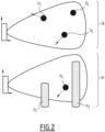
- a combination of two identical sensors for example two radars, arranged so that their respective fields of vision are offset by 90° relative to each other is implemented, thus forming a first type of virtual "macro-sensor" whose effective field of vision corresponds to the intersection of the two fields of vision of the two sensors forming it.
- a first radar of this macro-sensor detects potential obstructions and provides their horizontal azimuth, the distance between the obstruction and the aircraft, the estimated size as well as the associated velocity vector.
- the second radar of this macro-sensor also detects the same obstructions, provides their vertical azimuth, the distance between the obstruction and the aircraft, the estimated size as well as the associated velocity vector.
- FIG. 2 schematically illustrates the common vision of obstructions O 1 , O 2 , O 3 seen by these two separate radars, in the horizontal plane 38 delivered for example by the first radar, and in the vertical plane 40 delivered for example by the second radar oriented 90° relative to the first radar.
- the obstruction parameters delivered by each of the radars forming the macro-sensor are prioritized to associate the same obstruction, for example O 1 , both in the horizontal plane 38 and in the vertical plane 40.
- the value of the absolute obstruction speed delivered by the two radars is first used, then the obstruction distance from the aircraft, then the size (the size being less of a priority and being able to differ for the same obstruction between the size seen on the horizontal plane 38 and that seen on the vertical plane 40).
- two obstructions detected respectively by each of the radars and first presenting a similar relative longitudinal speed vector in direction (i.e. representative of an approach, a distance, a stationary position) and in norm are considered as potentially being associated with the same obstruction, which is then confirmed when the aircraft-obstruction distance is identical or almost identical and possibly reconfirmed by the detected size.
- two obstructions having the same speed of movement, located at the same distance and having the same size have a probability of being identical greater than 90%.
- the second radar capable of delivering information in the vertical plane 40 intervenes to supplement the information from the first radar (and not the reverse) because, according to a particular aspect of the invention, the information on the horizontal location of the obstruction is considered more important than the height information.
- Such a first macro-sensor solution based on two radars whose orientation is offset by 90° relative to each other is capable of providing height information at a lower cost.
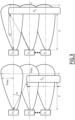
- Another arrangement of sensor(s) is suitable for being implemented according to the invention as a variant, and is based on a second type of virtual macro-sensor formed of at least three COTS sensors arranged offset at least vertically and suitable for applying a triangulation illustrated by the figures 3 And 4 described below.
- Each sensor of the second type of macro-sensor is capable of acquiring the pulses emitted by the other sensors while identifying their origin separately.
- the different sensors share the same time reference and operate on the same frequency ranges.
- the standardization module 12 is configured to process a signal provided by one of the sensors by standardizing this signal so as to then provide the processing module 14 with uniform data independent of the sensor technology used.
- the standardization module 12 is also capable of consolidating the information acquired by each sensor (or macro-sensor) so as to eliminate the surrounding noise (e.g. false radar echoes, light pollution, etc.) inherent in the technology of the sensor used.
- the standardization module 12 also provides tracking of obstruction(s).
- the standardization module 12 plays the role of interface between a sensor or a macro-sensor and the processing module 14 so as to present it with data of the same nature regardless of the sensor technology used or its origin of manufacture.
- the anti-collision device 10 (or 38) comprises as many standardization modules 12 as there are sensors, namely the whole number N.
- the standardization module 12 is also responsible for carrying out a first filtering of the data delivered (i.e. captured) by the sensor with which it is associated so that each standardization module 12 provides as output a set of M standardized data of the same nature.
- Such a standardization module 12 is specific to the technology and to the sensor manufacturer(s) with which it is associated, because it is capable of analyzing the data provided by such a sensor to transform them into data of the same type from one sensor to another.
- a standardization module 12 i associated with a sensor S i corresponding to a radar and a standardization module 12 j associated with a sensor S j corresponding to an ultrasonic sensor is capable of delivering, in the presence of an obstruction detected by each of the sensors S i and S j with which it is associated, a set of data Eb i and Eb j of identical types and distinct values associated respectively with each sensor S i and S j .
- the processing implemented by the functional core of the anti-collision device 10, namely the processing module 14 receiving such sets of standardized input data, is then simplified, which allows it to free itself from any dependence on the nature or origin of the sensor used and to concentrate on the reliable delivery of a information representative of the risk of collision incurred by any area of the aircraft.
- the uniformization module 12 i is located as close as possible to the sensor S i with which it is associated, or even integrated into it (not shown).
- a percentage of uncertainty is optionally associated with the value measured by the sensor considered.
- the standardization module 12 associated with each macro-sensor has a distributed architecture, not shown, comprising on the one hand for each sensor of the macro-sensor a first element (or software block) capable of carrying out the reception, acquisition and processing of the signal emitted by the sensors forming the virtual macro-sensor, such a first element being specific to the type of sensor considered.
- the standardization module 12 comprises a second element (or software block) capable of processing the data delivered by the first element associated with each sensor of the macro-sensor to produce as output, by macro-sensor, a complete three-dimensional (3D) standardized (i.e. generic) functional data.
- a second element or software block capable of processing the data delivered by the first element associated with each sensor of the macro-sensor to produce as output, by macro-sensor, a complete three-dimensional (3D) standardized (i.e. generic) functional data.
- the standardization module 12 is capable of being based on a quadruplet of data comprising, for example, the position of the sensors R 1 to R i , the identification of the sensor(s) which detected the obstruction from their emissions alone and/or from all of the emissions, the distance at which the obstruction is seen.
- the standardization module 12 is able to determine by geometry at what approximate height the obstruction O 4 or O 3 , or Oe is located as illustrated by the figures 3 And 4 respectively illustrating the well-known principle of triangulation and determination of azimuth in the plane.
- a radar comprises a transmitting antenna A and four receiving antennas B 1 to B 4 each spaced by a distance l .
- hmax is a function of h'max corresponding to the height of the field of vision and the height (radio altitude) of the aircraft
- ⁇ j h'max corresponds to the total height of the half-zones not intersected by the obstruction (if any)
- d corresponds to the distance at which the obstruction is perceived.
- the optional completion module 16 capable of completing the set of standardized data from one sensor with that of another sensor is not implemented in view of the use of the second element of the standardization module 12.
- the data preprocessing module 18 is at least capable of merging the data from all the sets of standardized data Eb 1 , Eb 2 , ..., Eb i , ... Eb N according to a detection zone associated with each sensor S 1 , S 2 , ..., S i , ... S N and of transmitting them to the data processing module 14 is implemented to address more or less complete protection of the periphery of the wearer.
- such a preprocessing module 18 is firstly capable of adding a level of temporal filtering to the output of the standardization module 12 or to the output of the optional completion module 16, to eliminate the obstructions present for a duration less than a predefined duration, the value of such a predefined duration being capable of varying according to the absolute speed of the aircraft.
- the preprocessing module 18 is configured to compare the fusion of the data of all the sets of trivialized data Eb 1 , Eb 2 , ..., Eb i , ... Eb N to a history of merged data previously stored in the memory of the anti-collision device 10.
- the preprocessing module 18 is capable of successively implementing: the sorting of the obstructions of this current fusion, and this by position of each obstruction, then the allocation of an obstruction identifier, then the fusion of the obstructions detected by the different sensors, the concatenation of the obstructions whose detection zones are contiguous without overlapping, and the fusion of obstructions according to their position, their size and their speed when the detection zones overlap; two obstructions of similar sizes located in a neighboring area and with a similar velocity vector (heading and norm), being considered identical as described previously.
- a configurable tolerance is applied on each fusion parameter (uncertainty on the detection zone, tolerance on the size (a difference size category for example) and on the speed vector (+/- 10° in direction and +/- 15kts in value for example).
- an obstruction without an identifier is considered to be similar to an obstruction already having an identifier, the existing identifier with the lowest value is retained. If the two obstructions are not considered identical, they each keep their identifier.
- the preprocessing module 18 when the preprocessing module 18 does not have the speed data (due to the sensor technology), a greater tolerance is suitable for being applied to the position of the obstructions.
- a greater tolerance is suitable for being applied to the position of the obstructions.
- Each fusion associated with its time of obtaining is kept so as to form a history usable by the preprocessing module 18.
- This depth of history is also appropriate to take into account the coverage of the largest white zone 44 illustrated on the figure 5 in the case of a rotary wing aircraft. To determine this, we will take the angular aperture of the white zone which we will divide by a minimum average rotation speed of the aircraft. For example, if the white zone is 20° and we consider a minimum rotation speed of 18°/s, a history depth of 1.7s is applied because it is greater than the minimum depth of 1.5s previously defined.
- the history step corresponds, for example, to the frequency of the fastest sensor.
- the preprocessing module 18 is able to compare the result of the current merger with that of the different elements of the history. During this comparison, the period between two merger samples is, according to the invention, less than a predetermined time value, allowing the application of the hypothesis according to which the speed vector of the obstruction is almost constant. According to this hypothesis, the preprocessing module 18 is then able to implement an obstruction tracking from the history by projecting an obstruction from the history into the most recent merger.
- the preprocessing module 18 is able to deduce a variation in the distance between the obstruction and the aircraft (comparison of the relative position of the obstruction to that of the aircraft).
- the preprocessing module 18 therefore provides a synthetic view of the aircraft environment as well as the obstructions identified and tracked over time with their characteristics, namely: identifier of the obstruction, sensor(s) having detected the obstruction, position of the obstruction, size of the obstruction, probability of existence, elevation (depending on the type of sensor), speed vector of the obstruction (depending on the type of sensor or from the measurement of the movement of the obstruction between two samples) and variation in the distance between the obstruction and the aircraft.
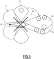
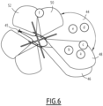
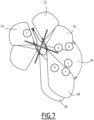
- FIGs 5 to 7 illustrate three distinct and successive samples of such a history.
- six distinct obstructions, a, b, c, d, e, f are represented as well as the coverage areas associated respectively with six sensors installed on the aircraft 45.
- the figure 5 represents the oldest sample
- the figure 6 represents an intermediate sample
- the figure 7 represents the last sample of the three successive samples illustrated.
- the sensor associated with the coverage area 46 detects three obstructions a, b, c
- the sensor associated with the coverage area 48 detects three obstructions c, d, e
- the sensor associated with the coverage area 50 detects an obstruction f.
- the result of the fusion preprocessing associated with this time T 0 is the identification of the six obstructions a, b, c, d, e, f which initialize the obstruction tracking.
- the aircraft 45 has moved, in particular by rotation around the yaw axis, the sensor associated with the coverage area 46 detects only two obstructions a, b, the sensor associated with the coverage area 48 detects three obstructions a, b, c, the sensors associated respectively with the coverage areas 50 and 52 detect the same obstruction f.
- the result of the fusion preprocessing associated with this instant T1 is the identification of four obstructions a, b, c and f, the obstructions e, f, not being detected at this instant T1 because they are present in the white zone 44, but the obstruction tracking compensates for this detection failure by referring to the sample from the previous instant T0 .
- the fusion preprocessing associated with this instant T 2 results in the identification of five obstructions, a, b, d, e and f, the obstruction c, not being detected at this instant T 2 because it is present in the white zone 44, but advantageously the obstruction tracking implemented by the preprocessing module 18 compensates for this detection flaw by referring to the history samples obtained at the previous instants T 0 and T 1 .
- the data processing module 14 is capable of generating, from said sets of standardized data Eb 1 , Eb 2 , ..., Eb i , ... Eb N , where appropriate completed by the completion module 16, and/or where appropriate preprocessed by the preprocessing module 18, at least one item of information representative of the evaluation of a level of risk corresponding to the presence or absence of obstruction and one item of alert information where appropriate.
- the data processing module 14 is in particular capable of determining the dangerousness of the situation and of calculating the remaining margins between the aircraft and each of the different obstructions located in the environment close to the aircraft, in order to inform the crew in the presence/absence of a risky obstruction and to alert them if necessary.
- the data processing module 14 is also capable of generating information representative of the presence or absence of drift of the aircraft in hovering flight.
- the data processing module 14 is capable of informing the crew or at least the pilot of the aircraft of a possible drift of a rotary wing aircraft capable of implementing a stationary flight phase.
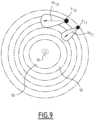
- the data processing module 14 is an electronic module capable of automatically implementing (i.e. without human intervention) all of its processing by considering the fixed reference point of the aircraft (the obstructions are therefore considered in relative positioning with respect to the device), and the distinction between alert (imminent risk) and warning (i.e.
- the presence of an obstruction not involving an immediate risk is made according to a set of predefined time thresholds before impact as illustrated by the figure 8 or the figure 9 according to two variants of concentric representations (rectangular and circular respectively around the aircraft), where the obstructions O 7 , O 9 , O 10 present a speed vector V O7 , V O9 , V O10 revealing that unless the aircraft changes trajectory 45 there is no risk of collision and will just be the subject of a warning from the pilot, while the obstructions O 8 and O 11 have a speed vector V O8 , V O11 directed towards the location of the aircraft 45 and will be the subject of a warning to the crew as long as it remains located in the surveillance zone 56 still associated with the warning broadcast, and will be the subject of an alert to the crew as soon as it is located in the most critical surveillance zone 58.
- the risk assessment processing implemented by the data processing 14 is carried out by comparing the time before impact with predefined time thresholds, these time thresholds being optionally adjustable by the pilot for example via a potentiometer type interface.
- Such risk assessment processing implemented by the data processing 14 aims to inform the crew or at least the pilot of the presence of a risky object in a surveillance zone of predefined volume around the aircraft.
- the aim pursued by the data processing module 14 for this risk assessment processing is therefore to consider as more dangerous the obstructions (including the terrain) tending to approach the aircraft most quickly or towards which the aircraft tends or could be likely to tend and to consider as less dangerous, or even harmless, the obstructions moving away from the aircraft or from which the aircraft moves away sufficiently quickly.
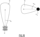
- the data processing module 14 is suitable for using, to perform the risk assessment, an extension of the speed vector of the aircraft 45 and of the obstruction or a TAWS type sensor to determine the obstructions at risk.
- sensor from the English clearance sensor , it is conventionally considered virtual surfaces calculated by the on-board computer and delimiting a volume of exploration of the space which is compared to the topography of the corresponding terrain as provided by an on-board terrain database.
- the detection principle is similar. The difference is that the sensor consists of defining a zone oriented according to the speed vector and covering the possible short-term trajectories of the aircraft as well as of the obstruction.
- the length of the zone is a function of the speed of movement of the aircraft and the predefined anticipation time. In the event that aircraft speed data is not available, a fixed length is considered or deduced from the data from the sensors (directly, or indirectly by measuring the aircraft movement between several data acquisitions).
- the straight line and bend trajectory cases are distinguished. If this information is not available, only the straight line case is considered.
- a zone 60 is centered on the speed vector V 62 of the aircraft 62, here a quadrotor, and another zone 64 is centered on the speed vector V O12 of the obstruction O 12 , the zones covering the possible movement of the aircraft 60 as well as of the obstruction O 12 having a configurable opening of a few degrees, 3° for example.
- the data processing module 14 is thus able to associate a risk level resulting directly from the closest threshold cut by one of the following three elements depending on the selected embodiment variant: the vector representing the variation in distance between the obstruction and the aircraft, or the speed vector of the obstruction, or the sensor of the obstruction.
- the data processing module 14 is able to implement an alert processing to warn the crew or at least the pilot of a risk of collision as soon as it is detected that an obstruction has crossed an alert threshold among the predefined time thresholds described in relation to the risk assessment processing.
- an alert threshold corresponds for example to the boundary between the surveillance zones 56 and 58 defined around the aircraft 45 on the Figures 8 And 9 .
- an alert is generated as soon as the speed vector/sensor of the aircraft intersects the speed vector of an obstruction, the obstruction in question then being considered as presenting a proven risk of collision.
- the position of the obstruction and of the ends of the aircraft are included in the calculation specific to be implemented automatically by the processing module 14.
- Such alert processing implemented by the processing module 14 is based on the assumption that given the vertical fields of vision and the range of the various sensors, flying over a detected obstruction, especially if it is mobile, does not correspond to a normal operation of the aircraft.
- the crew on board or remote in the case of a drone must therefore be warned in order to analyze the situation.
- alert thresholds can be defined according to a decreasing degree of severity, namely a first maximum alert threshold requiring avoidance if, for example, N a > 4.1 m.s -2 , a second alert threshold corresponding to a warning if, for example, 2.5 m.s -2 ⁇ N a ⁇ 4.1 m.s -2 , and a third alert threshold N a ⁇ 2.5 m.s -2 corresponding to a simple caution .
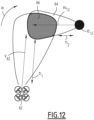
- the processing module 14 is able to implement a calculation specific to considering a vertical dimension using a vertical profile of the associated obstruction 0 13 , depending on the alert level previously determined, to an immediate avoidance maneuver E 1 , or to an evasive maneuver E 2 .
- a profile takes into account the current real performances of the aircraft 62. To do this, it is necessary for the on-board sensors to provide the elevation of the obstruction and for the obstruction to be fixed to the ground 68 (such a calculation not making sense for a moving obstruction).
- the processing module 14 when the processing module 14 is able to determine that the evasive maneuver E 2 is capable of passing beyond the obstruction 0 13 whose height is increased by a margin M a , then the level of the obstruction 0 13 in alert is automatically downgraded. On the contrary, when the processing module 14 is able to determine that the evasive maneuver E 2 conflicts with the obstruction 0 13 whose height is increased by a margin M a , then the associated alert level is maintained. In addition, when the processing module 14 is able to determine that the immediate avoidance maneuver E 1 conflicts with the obstruction height increased by a margin M a , the alert corresponding to the maximum alert threshold requiring avoidance is issued.
- the information provided by the alert processing has a higher priority than that relating to the risk level assessment processing, these two pieces of information are therefore considered exclusive of each other.
- the data processing module 14 is capable of implementing processing to provide information representative of a drift of the aircraft, depending on the type of sensor technology used.
- Such processing of providing information representative of a drift of the aircraft is particularly useful for missions during which the aircraft is subjected to a lifting of dust/snow (from the English brownout/whiteout ) present on a landing/takeoff zone by maintaining an aircraft, in particular a rotary wing, in stationary flight, where in the event of wind, the aircraft is likely to move without the pilot being able to detect it since he is likely to lose his visual references due to the dust/snow lifted.
- such processing for providing information representative of a drift of the aircraft consists in determining in real time a relative movement of the aircraft with respect to its environment by using the human-machine interface 30 connected to the anti-collision device 10.
- the anti-collision device is capable of presenting the evolution of the situation to the pilot of the aircraft. It is thus possible to present the variation in distance between the aircraft and the obstructions and to indicate (by comparison of the position of the aircraft with the fixed obstructions identified by the various sensors) a ground speed vector to the crew.
- the data processing module 14 when the aircraft is in stationary mode (information provided by a third-party avionics device of the aircraft or by the pilot himself via the IHM30), characterized by a non-zero height with respect to the ground and a substantially zero ground speed, the data processing module 14 is capable of comparing the evolution of the surrounding scene at ground level and in particular the position of the aircraft with respect to the obstructions identified as fixed. If the position evolves by more than a certain distance (configurable and corresponding for example to a rotor radius), information representative of a drift of the aircraft is automatically sent back to the crew.
- a certain distance configurable and corresponding for example to a rotor radius
- the data processing module 14 therefore provides as output a synthesis of the environment in terms of obstructions identified and monitored over time with their characteristics, namely an identifier of the obstruction, a position of the obstruction, the sensor(s) having detected the obstruction, the size of the obstruction, the probability of existence of the obstruction, the elevation of the obstruction, depending on the type of sensor, the risk assessment, the alert level, and optionally information representative of a drift of the aircraft.
- the supervision module 20 is configured to adapt the behavior of the sensors and the anti-collision device 10 according to the situation of the aircraft.
- the supervision module 20 has the task of managing the different sensors S 1 , S 2 , ..., S i , ... S N , by inhibiting/reducing the transmission power, depending on the configuration parameters D 1 , the operational modes 24, the current flight phase D 2 and the technology of the different sensors, it will inhibit/reduce the transmission power of the sensors concerned.
- Such management implemented by the supervision module is carried out from the configuration data D 1 containing in particular, for each sensor, a sensor identifier, the sensor technology, the position of the sensor on the aircraft, the field of vision, the power level emitted per functional mode 24, the power level emitted per flight phase D 2 , the functional modes 24 for which the sensor is inhibited/cut off, the flight phases D 2 for which the sensor is inhibited/cut off, a local database 32 (specific to the mission) or of a larger area (worldwide for example) containing the areas for which the use of such and such sensor technology is excluded.
- the supervision module 20 is capable of exploiting this database as well as the flight phases and other flight parameters D 2 of the machine (position for example) and capable of sending the necessary commands to the sensor(s) concerned via the physical interface connecting to the sensor(s) to reduce their power or stop them completely.
- the supervision module 20 is also capable of modulating the outputs of the display module 34 and/or the sound reproduction module 36 according to the functional mode 24 activated and/or the flight phase D 2 .
- the functional mode 24 activated and/or the flight phase D 2 .
- exclusive display mode only the outputs of the display module 34 are activated, the outputs of the sound reproduction module 36 are inhibited.
- the display module 34 is responsible for the graphic representation of the real-time situation of the aircraft and the room for maneuver it can have, accompanied, where appropriate, by the production of visual and sound alerts by the sound restitution module 36.
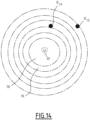
- Such a graphic representation can take several forms illustrated by the Figures 14 to 17 .
- FIG 14 is an example of a graphical representation including the location of the different obstructions O 14 and O 15 located in the field of vision of the different sensors S 1 , S 2 , ..., S i , ... S N .
- different colors are used to highlight the most risky obstructions (obstruction approaching or moving away, obstruction located at the same height or below the aircraft).
- FIG 15 is an example of a graphical representation providing in the monitoring zone 72 sensors S 1 , S 2 , ..., S i , ...S N information 74, 76 on direction by obstruction and information 70 on distance.
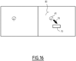
- FIG 16 is an example of a refined graphical representation for a head-up system for example, where only the direction 78 of the closest obstruction as well as the distance 70 separating it from the aircraft 45. According to an optional aspect, the direction 80 in which a second closest obstruction is located is added.
- the provision of the positioning of different risk thresholds and the distance between the aircraft (tip of the blades for example in the case of a helicopter) and the nearest obstruction are also represented.
- the color of the distance information or that of the obstruction can be adapted (red instead of amber for example, to indicate the emergency).
- the areas where the anti-collision device is "blind" i.e. white zone
- the sound reproduction module 36 is for its part capable of reproducing in the form of an audio signal a collision risk alert using for example a synthesized voice announcing the crossing of each threshold and the direction of the closest obstruction, or an audio signal whose frequency and/or intensity reflects the proximity and direction of the obstruction. To do this, the sound reproduction module 36 directly integrates an audio reproduction element or is linked to a remote element such as an earpiece for example.
- FIG 18 represents a first “basic” architecture in which the anti-collision device 10, 38 according to the present invention is autonomous (from the English stand-alone ) .
- the plurality 82 of sensors S 1 , S 2 , ..., S i , ... S N are installed on the aircraft and are capable of providing the captured data to the anti-collision device 10, 38 which directly outputs to the crew 84 in visual and/or audio form, information representative of the presence or absence of obstruction.
- the anti-collision device 10, 38 is not coupled to other data sources, such as a monitoring device (eg a TAWS terrain warning and avoidance device) and, for example, is not capable of anticipating changes in attitude of the aircraft.
- the anti-collision device 10, 38 corresponds for example to an electronic flight bag (EFB), a head -up display (HUD) or even a dedicated calculator.
- EFB electronic flight bag
- HUD head -up display
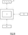
- FIG 19 represents a second “augmented” architecture in which the anti-collision device 10 38 is, in comparison with the basic architecture described previously in relation to the figure 18 , coupled (ie capable of cooperating, receiving and/or exchanging data with) a set 36 of other avionics instruments, such as a geolocation instrument (eg a GPS satellite geolocation system), an aerodynamic data calculator or anemometric computer (ADC from the English Air data computer ), an inertial unit (AHRS from the English Attitude and Heading reference System ), a radio altimeter, etc., with the aim of increasing the relevance of the information generated by the anti-collision device 10, 38 to the entire crew 84.
- a geolocation instrument eg a GPS satellite geolocation system
- ADC aerodynamic data calculator or anemometric computer
- AHRS inertial unit
- radio altimeter etc.
- Such an avionics protection system conforming to the augmented architecture of the figure 19 in addition to the capabilities of the protection avionics system conforming to the basic architecture of the figure 18 , is therefore also capable of recovering aircraft flight data, namely speed, position, altitude, etc., to optimize the relevance of the information generated according to the invention and representative of the presence or absence of an obstruction.
- the augmented architecture of the figure 19 is enhanced by coupling to an Integrated Surveillance System (ISS) including in particular an avionics terrain warning and avoidance system (TAWS or HTAWS) Awareness & Warning System ) which also allows the anti-collision device 10, 38 to retrieve information provided directly by the monitoring system such as flight phases, operational modes, etc.
- ISS Integrated Surveillance System
- TAWS avionics terrain warning and avoidance system
- Awareness & Warning System avionics terrain warning and avoidance system
- the terrain warning and avoidance device and the anti-collision device are therefore able to interact (i.e. to listen to each other).
- the terrain warning and avoidance device is activated in the cruise phase and deactivated at takeoff/landing, flight phases during which the anti-collision device according to the invention is activated.
- FIG 21 represents a fourth architecture where the anti-collision device 10, 38 according to the invention is integrated directly into a surveillance system 88 integrated into the aircraft comprising in particular an avionics device for warning and avoiding terrain.
- the structure of such an integration is shown diagrammatically in the figure 22 , and corresponds to all the elements of the anti-collision device of the figure 1 merged with all the elements classically associated with a TAWS device.
- pilot mode management module 26 the input parameter management module 28, the pilot command entry interface 30 and the database 32 are common to the anti-collision device and the TAWS device.
- the input parameter management module 28 is for example enriched with a fifth category D 5 of data more specific to the TAWS device, namely previously stored digital terrain and obstruction models.
- Such a fifth category D 5 is coupled to a specific database 90 with such digital terrain and obstruction models.
- the input parameter management module 28 conventionally supplies a reactive mode management module among, for example, predefined reactive modes M 1 , M 2 , M 3 , M 4 , M 5 , “tilt angle” BA, “tail-ground contact risk” TS (from the English Tail Strike ), an “altitude recall” mode CO (from the English Callout ).
- the reactive mode management module 28 is capable of delivering, to an AM alert management module, a reactive mode selected according to the input parameters and the output delivered by the piloting mode management module 26.
- the AM alert management module is also supplied by a mode prediction module 92 comprising at least one sensor 94, an element 96 for predicting collision with the terrain, an element 98 for predicting collision with an obstacle distinct from the terrain, an element 100 for linear prediction of collision with an obstacle distinct from the terrain.
- the outputs of the AM alert management module and of the mode prediction module 92 are capable of being reproduced by a display module 102 and/or by a sound reproduction module 104.
- the assembly formed by the anti-collision device and by the TAWS or HTAWS device is controlled by a supervision device 106 configured to control the activation/deactivation of the modules specific to the terrain warning and avoidance device and the activation/deactivation of the modules specific to the anti-collision device by means of input data of the same type, for example a flight phase, a pilot command, an external system command such as a “flight management system (FMS) command”, etc.
- FMS flight management system
- the supervision device 106 comprises in particular a module 108 for global monitoring of the situation of the aircraft and an alert supervisor 110 capable of arbitrating/selecting the visual and oral information coming from the anti-collision device according to the invention and/or coming from the TAWS or HTAWS device in order to choose the most relevant information to present according to the flight phase/the functional mode engaged to the crew by means of a display module 112 and/or a sound restitution module 114.
- the 106 supervision device is also capable of managing any overlap in terms of protection as well as the priorities between the different information to be sent to the crew.
- the anti-collision method 116 implemented by the anti-collision device 10, 38 comprises a first optional supervision step 118 for controlling (i.e. activating/deactivating, modulating the transmission power, etc.) the N sensors S 1 , S 2 , ..., S i , ... S N as a function of at least one input parameter of the categories D 1 to D 4 previously described, each sensor S 1 , S 2 , ..., S i , ... S N being capable of respectively delivering its own set of captured data S 1 , S 2 , ..., S i , ... S N as a function of the proximity of at least one obstruction.
- a first optional supervision step 118 for controlling (i.e. activating/deactivating, modulating the transmission power, etc.) the N sensors S 1 , S 2 , ..., S i , ... S N as a function of at least one input parameter of the categories D 1 to D 4 previously described, each sensor S 1 , S 2 , ..., S
- the anti-collision device 10 implements a standardization of the data captured specifically by each sensor to respectively deliver a set of standardized (i.e. generic) data formed from a plurality of types of data identical from one set of standardized data to another.
- a set of standardized (i.e. generic) data formed from a plurality of types of data identical from one set of standardized data to another.
- the anti-collision device 10, 38 implements a completion making it possible to complete, from a set of standardized data Eb i associated with one of the sensors S i , at least one missing value associated with a type, of the plurality of identical data types of a set of standardized data Eb j of another sensor S j of the plurality of sensors S 1 , S 2 , ..., S i , ... S N of the aircraft.
- the anti-collision device 10, 38 implements a preprocessing making it possible to merge the data from all the sets of trivialized data Eb 1 , Eb 2 , ..., Eb i , ... Eb N according to a detection zone associated with each sensor S 1 , S 2 , ..., S i , ... S N and to transmit them to the data processing module 14, and where appropriate during which, is or are applied: a temporal filtering to each set of trivialized data Eb 1 , Eb 2 , ..., Eb i , ...
- Eb N so as to eliminate the data associated with an obstruction whose duration of presence near the aircraft is less than a predetermined threshold, and/or a comparison of the fusion of the data from all the sets of trivialized data Eb 1 , Eb 2 , ..., Eb i , ... Eb N with a history of previously merged data memorized.
- the anti-collision device 10, 38 implements a processing of the generic data, corresponding directly, or obtained from the standardized data to generate at least one item of information representative of the presence or absence of obstruction(s).
- the anti-collision device 10, 38 implements a step of restitution to the crew or at least to the pilot of the information representative of the presence or absence of obstruction(s).
- the anti-collision device and the anti-collision method according to the invention coupled or not to a TAWS or HTAWS device, make it possible to improve the safety of the aircraft by covering situations where the aircraft operates, for example, at low speed with low lateral and vertical separation margins relative to fixed or moving artificial obstacles located nearby (take-off, landing, hovering and taxi phases) but also the so-called low-altitude flight phases where the aircraft operates close to the ground, all while freeing itself from the origin and technology of the sensors used, which are taken advantage of via the trivialization of the interface between the sensors and the functional core 14 of the anti-collision device 10, 38 according to the invention.
Landscapes
- Engineering & Computer Science (AREA)
- Physics & Mathematics (AREA)
- Aviation & Aerospace Engineering (AREA)
- General Physics & Mathematics (AREA)
- Radar, Positioning & Navigation (AREA)
- Remote Sensing (AREA)
- Computer Networks & Wireless Communication (AREA)
- Electromagnetism (AREA)
- Signal Processing (AREA)
- Automation & Control Theory (AREA)
- Health & Medical Sciences (AREA)
- Computing Systems (AREA)
- General Health & Medical Sciences (AREA)
- Medical Informatics (AREA)
- Traffic Control Systems (AREA)
- Radar Systems Or Details Thereof (AREA)
- Air Bags (AREA)
Claims (11)
- Kollisionsvermeidungsvorrichtung (10, 38) eines Luftfahrzeugs, umfassend eine Vielzahl von Sensoren (S1, S2, ..., Si, ...SN), die Vielzahl von Sensoren (S1, S2, ..., Si, ...SN) umfassend mindestens zwei verschiedene Sensoren (Si, Sj), wobei jeder Sensor (S1, S2, ..., Si, ...SN) geeignet ist, um jeweils seinen eigenen Satz erfasster Daten (S1, S2, ..., Si, ...SN) abhängig von der Nähe mindestens eines Hindernisses bereitzustellen,
die Kollisionsvermeidungsvorrichtung (10, 38)
umfassend:- mindestens ein Datenvereinheitlichungsmodul (12), das geeignet ist, um mindestens einen Satz erfasster Daten (Eci) in einen entsprechenden Satz banalisierter Daten (Ebi) umzuwandeln, wobei jeder Satz banalisierter Daten (Ebi), der jeweils mit mindestens einem Sensor (Ci) assoziiert ist, aus einer Vielzahl von Datentypen gebildet wird, die von einem zum anderen Satz banalisierter Daten identisch sind,- ein Datenverarbeitungsmodul (14), das geeignet ist, um aus den Sätzen banalisierter Daten (Eb1, Eb2, ..., Ebi, ...EbN) mindestens eine Information zu erzeugen, die repräsentativ für das Vorhandensein oder die Abwesenheit eines Hindernisses oder von Hindernissen ist, und- ein Datenvorverarbeitungsmodul (18), das zumindest geeignet ist, um die Daten aller Sätze banalisierter Daten (Eb1, Eb2, ..., Ebi, ...EbN) abhängig von einem Erfassungsbereich, der mit jedem Sensor (S1, S2, ..., Si, ...SN) assoziiert ist, zu vereinen und sie an das Datenverarbeitungsmodul zu übertragen. - Vorrichtung (10, 38) nach Anspruch 1, wobei die Kollisionsvermeidungsvorrichtung (10, 38) ferner ein Überwachungsmodul (20) umfasst, das geeignet ist, um die Vielzahl von Sensoren (S1, S2, ..., Si, ...SN) abhängig von mindestens einem Eingangsparameter zu steuern, der zu der Gruppe gehört, die mindestens Folgendes umfasst:- einen Sensorkonfigurationsparameter (D1);- einen Flugparameter (D2) des Luftfahrzeugs;- einen Parameter (D3), der repräsentativ für mindestens eine Mission des Luftfahrzeugs ist;- einen Parameter (D4), der repräsentativ für einen von dem Piloten eingegebenen Steuerbefehl ist;- eine Information (22), die repräsentativ für die aktuelle Flugphase des Luftfahrzeugs ist;- einen Parameter (24), der repräsentativ für den Betriebsmodus der Steuerung ist.
- Vorrichtung (10, 38) nach Anspruch 1 oder 2, wobei die Vielzahl identischer Datentypen in Anwesenheit eines erfassten Hindernisses mindestens die folgenden drei Datentypen umfasst:- mindestens Daten, die repräsentativ für eine Hindernisposition sind;- mindestens Daten, die repräsentativ für die Wahrscheinlichkeit einer Hinderniserfassung sind;- mindestens Daten, die repräsentativ für die Hindernisgröße sind.
- Vorrichtung (10, 38) nach einem der vorherigen Ansprüche, ferner umfassend ein Vervollständigungsmodul (16), das geeignet ist, um ausgehend von einem Satz banalisierter Daten (Ebi), der mit einem der Sensoren (Si), mindestens einen fehlenden Wert, der mit einem Typ assoziiert ist, aus der Vielzahl identischer Datentypen eines Satzes banalisierter Daten (Ebj) eines anderen Sensors (Sj) aus der Vielzahl von Sensoren (S1, S2, ..., Si, ...SN) des Luftfahrzeugs zu vervollständigen.
- Vorrichtung (10, 38) nach einem der vorherigen Ansprüche, wobei das Vorverarbeitungsmodul (18) ferner konfiguriert ist, um eine Zeitfilterung auf jeden Satz banalisierter Daten (Eb1, Eb2, ..., Ebi, ...EbN), die Daten eliminiert, die mit einem Hindernis assoziiert sind, dessen Dauer der Anwesenheit in der Nähe des Luftfahrzeugs unter einem vorbestimmten Schwellenwert ist.
- Vorrichtung (10, 38) nach einem der vorherigen Ansprüche, wobei das Vorverarbeitungsmodul (18) ferner konfiguriert ist, um das Vereinen von Daten aller Sätze banalisierter Daten (Eb1, Eb2, ..., Ebi, ...EbN) mit einem zuvor gespeicherten Verlauf von vereinten Daten zu vergleichen.
- Vorrichtung (10, 38) nach einem der vorherigen Ansprüche, wobei, wenn mindestens einer der Sensoren (S1, S2, ..., Si, ...SN) des Luftfahrzeugs geeignet ist, um die relative Geschwindigkeit eines Hindernisses zu bestimmen, das Datenverarbeitungsmodul (14) auch geeignet ist, um Informationen zu erzeugen, die repräsentativ für das Vorhandensein oder Nichtvorhandensein eines Driftens des Luftfahrzeugs in Schwebeflug sind.
- Avioniksystem zum Schutz eines Luftfahrzeugs, umfassend eine Warn- und Vermeidungsvorrichtung des Reliefs und eine Kollisionsvermeidungsvorrichtung (10, 38) nach einem der vorherigen Ansprüche, wobei die Warn- und Vermeidungsvorrichtung des Reliefs und die Kollisionsvermeidungsvorrichtung (10, 38) jeweils konfiguriert sind, um sich anhand mindestens eines gleichartigen Eingangsdatums gemäß einem vorbestimmten Aktivierungs-/Deaktivierungsgrad zu aktivieren/deaktivieren.
- Verfahren (116) zur Kollisionsvermeidung eines Luftfahrzeugs, umfassend eine Vielzahl von Sensoren (S1, S2, ..., Si, ...SN), die Vielzahl von Sensoren (S1, S2, ..., Si, ...SN) umfassend mindestens zwei verschiedene Sensoren (Si, Sj), wobei jeder Sensor (S1, S2, ..., Si, ...SN) geeignet ist, um jeweils seinen eigenen Satz erfasster Daten (Ec1, Ec2, ..., Eci, ...EcN) abhängig von der Nähe mindestens eines Hindernisses bereitzustellen,
wobei das Verfahren durch eine elektronische Überwachungsvorrichtung (10, 38) implementiert wird und mindestens Folgendes umfasst:- eine Vereinheitlichung (120) von Daten von jedem Satz erfasster Daten (Eci) in einen entsprechenden Satz banalisierter Daten (Ebi), wobei jeder Satz banalisierter Daten (Ebi), der jeweils mit mindestens einem Sensor (Ci) assoziiert ist, aus einer Vielzahl (PT)von Datentypen gebildet wird, die von einem zum anderen Satz banalisierter Daten identisch sind,- eine Vorverarbeitung (124) von Daten, die die Daten aller Sätze banalisierter Daten abhängig von einem Erfassungsbereich vereint, der mit jedem Sensor assoziiert ist und sie an ein Datenverarbeitungsmodul überträgt, und- eine Verarbeitung (126) von Daten, die ausgehend von den Sätzen banalisierter Daten (Eb1, Eb2, ..., Ebi, ...EbN) mindestens eine Information erzeugt, die repräsentativ für das Vorhandensein oder die Abwesenheit eines Hindernisses oder von Hindernissen ist. - Verfahren (116) nach Anspruch 9, wobei das Verfahren ferner eine Überwachung umfasst,
die die Vielzahl von Sensoren (S1, S2, ..., Si, ...SN)
abhängig von mindestens einem Eingangsparameter steuert, der zu der Gruppe gehört, die mindestens Folgendes umfasst:- einen Sensorkonfigurationsparameter (D1);- einen Flugparameter (D2) des Luftfahrzeugs;- einen Parameter (D3), der repräsentativ für mindestens eine Mission des Luftfahrzeugs ist;- einen Parameter (D4), der repräsentativ für einen von dem Piloten eingegebenen Steuerbefehl ist;- eine Information (22), die repräsentativ für die aktuelle Flugphase des Luftfahrzeugs ist;- einen Parameter (24), der repräsentativ für den Betriebsmodus der Steuerung ist. - Computerprogrammprodukt, umfassend Softwareanweisungen, die, wenn sie von einem Computer ausgeführt werden, ein Verfahren nach einem der Ansprüche 9 bis 10 implementieren.
Applications Claiming Priority (1)
| Application Number | Priority Date | Filing Date | Title |
|---|---|---|---|
| FR1801152A FR3087915B1 (fr) | 2018-10-31 | 2018-10-31 | Dispositif anticollision, systeme avionique de protection, procede d'anticollision et programme d'ordinateur associes |
Publications (2)
| Publication Number | Publication Date |
|---|---|
| EP3648439A1 EP3648439A1 (de) | 2020-05-06 |
| EP3648439B1 true EP3648439B1 (de) | 2024-09-25 |
Family
ID=66165999
Family Applications (1)
| Application Number | Title | Priority Date | Filing Date |
|---|---|---|---|
| EP19205779.2A Active EP3648439B1 (de) | 2018-10-31 | 2019-10-29 | Vorrichtung zur anti-collision, avionisches schutzsystem, verfahren zur anti-collision und computerprogramm |
Country Status (4)
| Country | Link |
|---|---|
| US (1) | US10854097B2 (de) |
| EP (1) | EP3648439B1 (de) |
| CN (1) | CN111196369B (de) |
| FR (1) | FR3087915B1 (de) |
Families Citing this family (8)
| Publication number | Priority date | Publication date | Assignee | Title |
|---|---|---|---|---|
| EP3680180B1 (de) * | 2019-01-08 | 2021-06-02 | AIRBUS HELICOPTERS DEUTSCHLAND GmbH | Flugzeug mit sicherheitsabstandanzeigevorrichtung |
| WO2021065543A1 (ja) * | 2019-09-30 | 2021-04-08 | ソニー株式会社 | 情報処理装置、情報処理方法、およびプログラム |
| SE544549C2 (en) * | 2020-03-13 | 2022-07-12 | Saab Ab | A method, computer program product, system and craft for collision avoidance |
| US20250265936A1 (en) * | 2020-07-31 | 2025-08-21 | Aurora Flight Sciences Corporation, a subsidiary of The Boeing Company | Detecting Conflict Along a Route of a Robot |
| JP7413548B2 (ja) * | 2020-08-25 | 2024-01-15 | 株式会社デンソー | 走行支援装置 |
| GB2602999B (en) * | 2021-01-25 | 2025-03-12 | Infomode Ltd | Object detection system |
| FR3120229B1 (fr) * | 2021-02-26 | 2025-06-13 | Thales Sa | Système électronique de détection et de gestion d’un dysfonctionnement dans le comportement en vol d’un drone, procédé et programme d’ordinateur associés |
| CN115862389B (zh) * | 2022-11-18 | 2025-04-08 | 中国航空无线电电子研究所 | 一种机载防撞系统的架构 |
Family Cites Families (11)
| Publication number | Priority date | Publication date | Assignee | Title |
|---|---|---|---|---|
| US4495589A (en) * | 1982-09-20 | 1985-01-22 | Crane Co. | Aircraft ground velocity determination system |
| FR2773609B1 (fr) | 1998-01-12 | 2000-02-11 | Dassault Electronique | Procede et dispositif d'anti-collision terrain pour aeronef, a visualisation perfectionnee |
| US10331136B2 (en) * | 2006-02-27 | 2019-06-25 | Perrone Robotics, Inc. | General purpose robotics operating system with unmanned and autonomous vehicle extensions |
| FR2913800B1 (fr) * | 2007-03-13 | 2010-08-20 | Thales Sa | Dispositifs et procedes de filtrage d'alertes anti-collision de terrain et d'obstacles pour aeronef |
| US20130321169A1 (en) * | 2012-05-30 | 2013-12-05 | Honeywell International Inc. | Airport surface collision-avoidance system (ascas) |
| US9581692B2 (en) * | 2012-05-30 | 2017-02-28 | Honeywell International Inc. | Collision-avoidance system for ground crew using sensors |
| US9519286B2 (en) * | 2013-03-19 | 2016-12-13 | Robotic Research, Llc | Delayed telop aid |
| CN103413465A (zh) * | 2013-07-08 | 2013-11-27 | 中国航空无线电电子研究所 | 一种机载防撞与近地告警监视系统及监视方法 |
| CN104743128A (zh) * | 2015-04-23 | 2015-07-01 | 沈阳飞羽航空科技有限公司 | 通用飞机机组综合警告系统 |
| CN105083573B (zh) * | 2015-09-22 | 2018-07-13 | 西华大学 | 一种防撞无人飞行器系统及其防撞方法 |
| CN108319982A (zh) * | 2018-02-06 | 2018-07-24 | 贵州电网有限责任公司 | 一种电力巡线无人机多传感器数据融合障碍物检测方法 |
-
2018
- 2018-10-31 FR FR1801152A patent/FR3087915B1/fr active Active
-
2019
- 2019-10-25 US US16/664,342 patent/US10854097B2/en active Active
- 2019-10-29 EP EP19205779.2A patent/EP3648439B1/de active Active
- 2019-10-30 CN CN201911046010.8A patent/CN111196369B/zh active Active
Also Published As
| Publication number | Publication date |
|---|---|
| FR3087915A1 (fr) | 2020-05-01 |
| CN111196369B (zh) | 2024-07-05 |
| US20200135037A1 (en) | 2020-04-30 |
| CN111196369A (zh) | 2020-05-26 |
| US10854097B2 (en) | 2020-12-01 |
| EP3648439A1 (de) | 2020-05-06 |
| FR3087915B1 (fr) | 2021-09-17 |
Similar Documents
| Publication | Publication Date | Title |
|---|---|---|
| EP3648439B1 (de) | Vorrichtung zur anti-collision, avionisches schutzsystem, verfahren zur anti-collision und computerprogramm | |
| US10176723B2 (en) | Obstacle avoidance system | |
| US20160247406A1 (en) | Automated aircraft ground threat avoidance system | |
| FR2932279A1 (fr) | Dispositif et procede de surveillance des obstructions dans l'environnement proche d'un aeronef. | |
| CA2525748A1 (fr) | Systeme de protection automatique du vol pour aeronef | |
| FR3070527A1 (fr) | Procede et dispositif d'evitement d'un objet par detection de son rapprochement d'un aeronef | |
| FR2932306A1 (fr) | Procede et dispositif d'aide a la navigation pour un aeronef vis-a-vis des obstacles. | |
| FR2923623A1 (fr) | Systeme de securisation d'un plan de vol pour aeronef | |
| FR2932895A1 (fr) | Procede et systeme d'aide a la navigation aerienne permettant de maintenir des marges verticales | |
| FR2949569A1 (fr) | Systeme d'aide a la navigation a affichage 3d et son procede d'affichage | |
| EP1057160A1 (de) | Gerät zur vermeidung von flugzeugkollisionen mit dem boden | |
| FR2985353A1 (fr) | Dispositif d'aide a la gestion d'un vol d'un aeronef | |
| FR3110999A1 (fr) | Procédé et système de détection et d’évitement d’obstacles à plusieurs espaces de détection pour aéronef | |
| EP3388916A1 (de) | Übertragungsverfahren von flugparametern von einem anführenden luftfahrzeug an ein eindringendes luftfahrzeug | |
| FR2928021A1 (fr) | Procede et dispositif de detection d'un aeronef environnant. | |
| EP2407953B1 (de) | Verbessertes Pilotenassistenzverfahren für Luftfahrzeug | |
| FR2897839A1 (fr) | Procede et dispositif d'ajustememnt automatique d'une image d'un ecran de navigation d'aeronef. | |
| FR3014233A1 (fr) | Systeme d'aeronef pour signaler la presence d'un obstacle, aeronef et procede de detection d'obstacle | |
| WO2008145593A1 (fr) | Dispositif de visualisation pour aéronef comprenant des moyens d'affichage d'une symbologie de navigation dédiée a l'évitement d'obstacles | |
| EP3866136B1 (de) | Verfahren und system zur navigationshilfe für ein luftfahrzeug durch erkennung von maritimen objekten beim anflug, im stationären flugzustand oder bei der landung | |
| CA3047766C (fr) | Systeme d'aide au pilotage d'un aeronef, aeronef associe et procede d'aide au pilotage de cet aeronef | |
| FR3061343A1 (fr) | Systeme d'aide a l'atterrissage d'un aeronef a voilure tournante sur une plateforme offshore | |
| FR3026216A1 (fr) | Systeme d'assistance au pilotage d'une plate-forme, et procede associe | |
| US11130592B1 (en) | Method of avoiding controlled flight into terrain and a controlled flight into terrain avoidance system | |
| FR2954543A1 (fr) | Procede et systeme de generation d'alertes pour aeronef en cas de piste invalide. |
Legal Events
| Date | Code | Title | Description |
|---|---|---|---|
| PUAI | Public reference made under article 153(3) epc to a published international application that has entered the european phase |
Free format text: ORIGINAL CODE: 0009012 |
|
| STAA | Information on the status of an ep patent application or granted ep patent |
Free format text: STATUS: THE APPLICATION HAS BEEN PUBLISHED |
|
| STAA | Information on the status of an ep patent application or granted ep patent |
Free format text: STATUS: REQUEST FOR EXAMINATION WAS MADE |
|
| AK | Designated contracting states |
Kind code of ref document: A1 Designated state(s): AL AT BE BG CH CY CZ DE DK EE ES FI FR GB GR HR HU IE IS IT LI LT LU LV MC MK MT NL NO PL PT RO RS SE SI SK SM TR |
|
| AX | Request for extension of the european patent |
Extension state: BA ME |
|
| 17P | Request for examination filed |
Effective date: 20200422 |
|
| RBV | Designated contracting states (corrected) |
Designated state(s): AL AT BE BG CH CY CZ DE DK EE ES FI FR GB GR HR HU IE IS IT LI LT LU LV MC MK MT NL NO PL PT RO RS SE SI SK SM TR |
|
| STAA | Information on the status of an ep patent application or granted ep patent |
Free format text: STATUS: EXAMINATION IS IN PROGRESS |
|
| 17Q | First examination report despatched |
Effective date: 20200724 |
|
| P01 | Opt-out of the competence of the unified patent court (upc) registered |
Effective date: 20230425 |
|
| REG | Reference to a national code |
Ref legal event code: R079 Free format text: PREVIOUS MAIN CLASS: H04L0029080000 Ref country code: DE Ref document number: 602019059369 Country of ref document: DE Ipc: H04L0067120000 |
|
| GRAP | Despatch of communication of intention to grant a patent |
Free format text: ORIGINAL CODE: EPIDOSNIGR1 |
|
| STAA | Information on the status of an ep patent application or granted ep patent |
Free format text: STATUS: GRANT OF PATENT IS INTENDED |
|
| RIC1 | Information provided on ipc code assigned before grant |
Ipc: H04W 4/42 20180101ALN20240426BHEP Ipc: H04W 4/38 20180101ALN20240426BHEP Ipc: G05D 1/00 20060101ALI20240426BHEP Ipc: G08G 5/04 20060101ALI20240426BHEP Ipc: G08G 5/00 20060101ALI20240426BHEP Ipc: H04L 67/565 20220101ALI20240426BHEP Ipc: H04L 67/12 20220101AFI20240426BHEP |
|
| INTG | Intention to grant announced |
Effective date: 20240514 |
|
| GRAS | Grant fee paid |
Free format text: ORIGINAL CODE: EPIDOSNIGR3 |
|
| GRAA | (expected) grant |
Free format text: ORIGINAL CODE: 0009210 |
|
| STAA | Information on the status of an ep patent application or granted ep patent |
Free format text: STATUS: THE PATENT HAS BEEN GRANTED |
|
| AK | Designated contracting states |
Kind code of ref document: B1 Designated state(s): AL AT BE BG CH CY CZ DE DK EE ES FI FR GB GR HR HU IE IS IT LI LT LU LV MC MK MT NL NO PL PT RO RS SE SI SK SM TR |
|
| REG | Reference to a national code |
Ref country code: GB Ref legal event code: FG4D Free format text: NOT ENGLISH |
|
| REG | Reference to a national code |
Ref country code: CH Ref legal event code: EP |
|
| REG | Reference to a national code |
Ref country code: DE Ref legal event code: R096 Ref document number: 602019059369 Country of ref document: DE |
|
| REG | Reference to a national code |
Ref country code: IE Ref legal event code: FG4D Free format text: LANGUAGE OF EP DOCUMENT: FRENCH |
|
| REG | Reference to a national code |
Ref country code: LT Ref legal event code: MG9D |
|
| PG25 | Lapsed in a contracting state [announced via postgrant information from national office to epo] |
Ref country code: NO Free format text: LAPSE BECAUSE OF FAILURE TO SUBMIT A TRANSLATION OF THE DESCRIPTION OR TO PAY THE FEE WITHIN THE PRESCRIBED TIME-LIMIT Effective date: 20241225 |
|
| PG25 | Lapsed in a contracting state [announced via postgrant information from national office to epo] |
Ref country code: GR Free format text: LAPSE BECAUSE OF FAILURE TO SUBMIT A TRANSLATION OF THE DESCRIPTION OR TO PAY THE FEE WITHIN THE PRESCRIBED TIME-LIMIT Effective date: 20241226 Ref country code: FI Free format text: LAPSE BECAUSE OF FAILURE TO SUBMIT A TRANSLATION OF THE DESCRIPTION OR TO PAY THE FEE WITHIN THE PRESCRIBED TIME-LIMIT Effective date: 20240925 |
|
| PG25 | Lapsed in a contracting state [announced via postgrant information from national office to epo] |
Ref country code: BG Free format text: LAPSE BECAUSE OF FAILURE TO SUBMIT A TRANSLATION OF THE DESCRIPTION OR TO PAY THE FEE WITHIN THE PRESCRIBED TIME-LIMIT Effective date: 20240925 |
|
| PG25 | Lapsed in a contracting state [announced via postgrant information from national office to epo] |
Ref country code: LV Free format text: LAPSE BECAUSE OF FAILURE TO SUBMIT A TRANSLATION OF THE DESCRIPTION OR TO PAY THE FEE WITHIN THE PRESCRIBED TIME-LIMIT Effective date: 20240925 |
|
| PG25 | Lapsed in a contracting state [announced via postgrant information from national office to epo] |
Ref country code: RS Free format text: LAPSE BECAUSE OF FAILURE TO SUBMIT A TRANSLATION OF THE DESCRIPTION OR TO PAY THE FEE WITHIN THE PRESCRIBED TIME-LIMIT Effective date: 20241225 |
|
| REG | Reference to a national code |
Ref country code: NL Ref legal event code: MP Effective date: 20240925 |
|
| PG25 | Lapsed in a contracting state [announced via postgrant information from national office to epo] |
Ref country code: RS Free format text: LAPSE BECAUSE OF FAILURE TO SUBMIT A TRANSLATION OF THE DESCRIPTION OR TO PAY THE FEE WITHIN THE PRESCRIBED TIME-LIMIT Effective date: 20241225 Ref country code: NO Free format text: LAPSE BECAUSE OF FAILURE TO SUBMIT A TRANSLATION OF THE DESCRIPTION OR TO PAY THE FEE WITHIN THE PRESCRIBED TIME-LIMIT Effective date: 20241225 Ref country code: LV Free format text: LAPSE BECAUSE OF FAILURE TO SUBMIT A TRANSLATION OF THE DESCRIPTION OR TO PAY THE FEE WITHIN THE PRESCRIBED TIME-LIMIT Effective date: 20240925 Ref country code: GR Free format text: LAPSE BECAUSE OF FAILURE TO SUBMIT A TRANSLATION OF THE DESCRIPTION OR TO PAY THE FEE WITHIN THE PRESCRIBED TIME-LIMIT Effective date: 20241226 Ref country code: FI Free format text: LAPSE BECAUSE OF FAILURE TO SUBMIT A TRANSLATION OF THE DESCRIPTION OR TO PAY THE FEE WITHIN THE PRESCRIBED TIME-LIMIT Effective date: 20240925 Ref country code: BG Free format text: LAPSE BECAUSE OF FAILURE TO SUBMIT A TRANSLATION OF THE DESCRIPTION OR TO PAY THE FEE WITHIN THE PRESCRIBED TIME-LIMIT Effective date: 20240925 |
|
| REG | Reference to a national code |
Ref country code: AT Ref legal event code: MK05 Ref document number: 1727609 Country of ref document: AT Kind code of ref document: T Effective date: 20240925 |
|
| PG25 | Lapsed in a contracting state [announced via postgrant information from national office to epo] |
Ref country code: NL Free format text: LAPSE BECAUSE OF FAILURE TO SUBMIT A TRANSLATION OF THE DESCRIPTION OR TO PAY THE FEE WITHIN THE PRESCRIBED TIME-LIMIT Effective date: 20240925 |
|
| PG25 | Lapsed in a contracting state [announced via postgrant information from national office to epo] |
Ref country code: PT Free format text: LAPSE BECAUSE OF FAILURE TO SUBMIT A TRANSLATION OF THE DESCRIPTION OR TO PAY THE FEE WITHIN THE PRESCRIBED TIME-LIMIT Effective date: 20250127 Ref country code: IS Free format text: LAPSE BECAUSE OF FAILURE TO SUBMIT A TRANSLATION OF THE DESCRIPTION OR TO PAY THE FEE WITHIN THE PRESCRIBED TIME-LIMIT Effective date: 20250125 |
|
| PG25 | Lapsed in a contracting state [announced via postgrant information from national office to epo] |
Ref country code: SM Free format text: LAPSE BECAUSE OF FAILURE TO SUBMIT A TRANSLATION OF THE DESCRIPTION OR TO PAY THE FEE WITHIN THE PRESCRIBED TIME-LIMIT Effective date: 20240925 Ref country code: RO Free format text: LAPSE BECAUSE OF FAILURE TO SUBMIT A TRANSLATION OF THE DESCRIPTION OR TO PAY THE FEE WITHIN THE PRESCRIBED TIME-LIMIT Effective date: 20240925 |
|
| PG25 | Lapsed in a contracting state [announced via postgrant information from national office to epo] |
Ref country code: ES Free format text: LAPSE BECAUSE OF FAILURE TO SUBMIT A TRANSLATION OF THE DESCRIPTION OR TO PAY THE FEE WITHIN THE PRESCRIBED TIME-LIMIT Effective date: 20240925 |
|
| PG25 | Lapsed in a contracting state [announced via postgrant information from national office to epo] |
Ref country code: EE Free format text: LAPSE BECAUSE OF FAILURE TO SUBMIT A TRANSLATION OF THE DESCRIPTION OR TO PAY THE FEE WITHIN THE PRESCRIBED TIME-LIMIT Effective date: 20240925 Ref country code: AT Free format text: LAPSE BECAUSE OF FAILURE TO SUBMIT A TRANSLATION OF THE DESCRIPTION OR TO PAY THE FEE WITHIN THE PRESCRIBED TIME-LIMIT Effective date: 20240925 |
|
| PG25 | Lapsed in a contracting state [announced via postgrant information from national office to epo] |
Ref country code: CZ Free format text: LAPSE BECAUSE OF FAILURE TO SUBMIT A TRANSLATION OF THE DESCRIPTION OR TO PAY THE FEE WITHIN THE PRESCRIBED TIME-LIMIT Effective date: 20240925 Ref country code: PL Free format text: LAPSE BECAUSE OF FAILURE TO SUBMIT A TRANSLATION OF THE DESCRIPTION OR TO PAY THE FEE WITHIN THE PRESCRIBED TIME-LIMIT Effective date: 20240925 |
|
| PG25 | Lapsed in a contracting state [announced via postgrant information from national office to epo] |
Ref country code: IT Free format text: LAPSE BECAUSE OF FAILURE TO SUBMIT A TRANSLATION OF THE DESCRIPTION OR TO PAY THE FEE WITHIN THE PRESCRIBED TIME-LIMIT Effective date: 20240925 Ref country code: SK Free format text: LAPSE BECAUSE OF FAILURE TO SUBMIT A TRANSLATION OF THE DESCRIPTION OR TO PAY THE FEE WITHIN THE PRESCRIBED TIME-LIMIT Effective date: 20240925 |
|
| REG | Reference to a national code |
Ref country code: CH Ref legal event code: PL |
|
| REG | Reference to a national code |
Ref country code: DE Ref legal event code: R097 Ref document number: 602019059369 Country of ref document: DE |
|
| PG25 | Lapsed in a contracting state [announced via postgrant information from national office to epo] |
Ref country code: MC Free format text: LAPSE BECAUSE OF FAILURE TO SUBMIT A TRANSLATION OF THE DESCRIPTION OR TO PAY THE FEE WITHIN THE PRESCRIBED TIME-LIMIT Effective date: 20240925 |
|
| PG25 | Lapsed in a contracting state [announced via postgrant information from national office to epo] |
Ref country code: DK Free format text: LAPSE BECAUSE OF FAILURE TO SUBMIT A TRANSLATION OF THE DESCRIPTION OR TO PAY THE FEE WITHIN THE PRESCRIBED TIME-LIMIT Effective date: 20240925 |
|
| PG25 | Lapsed in a contracting state [announced via postgrant information from national office to epo] |
Ref country code: LU Free format text: LAPSE BECAUSE OF NON-PAYMENT OF DUE FEES Effective date: 20241029 Ref country code: BE Free format text: LAPSE BECAUSE OF NON-PAYMENT OF DUE FEES Effective date: 20241031 |
|
| PG25 | Lapsed in a contracting state [announced via postgrant information from national office to epo] |
Ref country code: CH Free format text: LAPSE BECAUSE OF NON-PAYMENT OF DUE FEES Effective date: 20241031 |
|
| PLBE | No opposition filed within time limit |
Free format text: ORIGINAL CODE: 0009261 |
|
| STAA | Information on the status of an ep patent application or granted ep patent |
Free format text: STATUS: NO OPPOSITION FILED WITHIN TIME LIMIT |
|
| REG | Reference to a national code |
Ref country code: BE Ref legal event code: MM Effective date: 20241031 |
|
| GBPC | Gb: european patent ceased through non-payment of renewal fee |
Effective date: 20241225 |
|
| 26N | No opposition filed |
Effective date: 20250626 |
|
| PG25 | Lapsed in a contracting state [announced via postgrant information from national office to epo] |
Ref country code: SE Free format text: LAPSE BECAUSE OF FAILURE TO SUBMIT A TRANSLATION OF THE DESCRIPTION OR TO PAY THE FEE WITHIN THE PRESCRIBED TIME-LIMIT Effective date: 20240925 |
|
| PG25 | Lapsed in a contracting state [announced via postgrant information from national office to epo] |
Ref country code: GB Free format text: LAPSE BECAUSE OF NON-PAYMENT OF DUE FEES Effective date: 20241225 |
|
| PG25 | Lapsed in a contracting state [announced via postgrant information from national office to epo] |
Ref country code: IE Free format text: LAPSE BECAUSE OF NON-PAYMENT OF DUE FEES Effective date: 20241029 |
|
| PGFP | Annual fee paid to national office [announced via postgrant information from national office to epo] |
Ref country code: DE Payment date: 20251015 Year of fee payment: 7 |
|
| PG25 | Lapsed in a contracting state [announced via postgrant information from national office to epo] |
Ref country code: HR Free format text: LAPSE BECAUSE OF FAILURE TO SUBMIT A TRANSLATION OF THE DESCRIPTION OR TO PAY THE FEE WITHIN THE PRESCRIBED TIME-LIMIT Effective date: 20240925 |
|
| PGFP | Annual fee paid to national office [announced via postgrant information from national office to epo] |
Ref country code: FR Payment date: 20251027 Year of fee payment: 7 |
|
| PG25 | Lapsed in a contracting state [announced via postgrant information from national office to epo] |
Ref country code: HU Free format text: LAPSE BECAUSE OF FAILURE TO SUBMIT A TRANSLATION OF THE DESCRIPTION OR TO PAY THE FEE WITHIN THE PRESCRIBED TIME-LIMIT; INVALID AB INITIO Effective date: 20191029 |