EP3646919B1 - Manufacturing method of plate precursor having needle-like protrusion, and manufacturing method of microneedle array - Google Patents
Manufacturing method of plate precursor having needle-like protrusion, and manufacturing method of microneedle array Download PDFInfo
- Publication number
- EP3646919B1 EP3646919B1 EP19200753.2A EP19200753A EP3646919B1 EP 3646919 B1 EP3646919 B1 EP 3646919B1 EP 19200753 A EP19200753 A EP 19200753A EP 3646919 B1 EP3646919 B1 EP 3646919B1
- Authority
- EP
- European Patent Office
- Prior art keywords
- needle
- protrusion
- plate precursor
- cutting tool
- manufacturing
- Prior art date
- Legal status (The legal status is an assumption and is not a legal conclusion. Google has not performed a legal analysis and makes no representation as to the accuracy of the status listed.)
- Active
Links
Images


Classifications
-
- B—PERFORMING OPERATIONS; TRANSPORTING
- B29—WORKING OF PLASTICS; WORKING OF SUBSTANCES IN A PLASTIC STATE IN GENERAL
- B29C—SHAPING OR JOINING OF PLASTICS; SHAPING OF MATERIAL IN A PLASTIC STATE, NOT OTHERWISE PROVIDED FOR; AFTER-TREATMENT OF THE SHAPED PRODUCTS, e.g. REPAIRING
- B29C33/00—Moulds or cores; Details thereof or accessories therefor
- B29C33/38—Moulds or cores; Details thereof or accessories therefor characterised by the material or the manufacturing process
- B29C33/3842—Manufacturing moulds, e.g. shaping the mould surface by machining
- B29C33/3857—Manufacturing moulds, e.g. shaping the mould surface by machining by making impressions of one or more parts of models, e.g. shaped articles and including possible subsequent assembly of the parts
- B29C33/3892—Preparation of the model, e.g. by assembling parts
-
- A—HUMAN NECESSITIES
- A61—MEDICAL OR VETERINARY SCIENCE; HYGIENE
- A61M—DEVICES FOR INTRODUCING MEDIA INTO, OR ONTO, THE BODY; DEVICES FOR TRANSDUCING BODY MEDIA OR FOR TAKING MEDIA FROM THE BODY; DEVICES FOR PRODUCING OR ENDING SLEEP OR STUPOR
- A61M37/00—Other apparatus for introducing media into the body; Percutany, i.e. introducing medicines into the body by diffusion through the skin
- A61M37/0015—Other apparatus for introducing media into the body; Percutany, i.e. introducing medicines into the body by diffusion through the skin by using microneedles
-
- B—PERFORMING OPERATIONS; TRANSPORTING
- B24—GRINDING; POLISHING
- B24B—MACHINES, DEVICES, OR PROCESSES FOR GRINDING OR POLISHING; DRESSING OR CONDITIONING OF ABRADING SURFACES; FEEDING OF GRINDING, POLISHING, OR LAPPING AGENTS
- B24B19/00—Single-purpose machines or devices for particular grinding operations not covered by any other main group
- B24B19/16—Single-purpose machines or devices for particular grinding operations not covered by any other main group for grinding sharp-pointed workpieces, e.g. needles, pens, fish hooks, tweezers or record player styli
-
- B—PERFORMING OPERATIONS; TRANSPORTING
- B29—WORKING OF PLASTICS; WORKING OF SUBSTANCES IN A PLASTIC STATE IN GENERAL
- B29C—SHAPING OR JOINING OF PLASTICS; SHAPING OF MATERIAL IN A PLASTIC STATE, NOT OTHERWISE PROVIDED FOR; AFTER-TREATMENT OF THE SHAPED PRODUCTS, e.g. REPAIRING
- B29C33/00—Moulds or cores; Details thereof or accessories therefor
- B29C33/38—Moulds or cores; Details thereof or accessories therefor characterised by the material or the manufacturing process
- B29C33/3842—Manufacturing moulds, e.g. shaping the mould surface by machining
-
- B—PERFORMING OPERATIONS; TRANSPORTING
- B29—WORKING OF PLASTICS; WORKING OF SUBSTANCES IN A PLASTIC STATE IN GENERAL
- B29C—SHAPING OR JOINING OF PLASTICS; SHAPING OF MATERIAL IN A PLASTIC STATE, NOT OTHERWISE PROVIDED FOR; AFTER-TREATMENT OF THE SHAPED PRODUCTS, e.g. REPAIRING
- B29C33/00—Moulds or cores; Details thereof or accessories therefor
- B29C33/42—Moulds or cores; Details thereof or accessories therefor characterised by the shape of the moulding surface, e.g. ribs or grooves
- B29C33/424—Moulding surfaces provided with means for marking or patterning
-
- A—HUMAN NECESSITIES
- A61—MEDICAL OR VETERINARY SCIENCE; HYGIENE
- A61K—PREPARATIONS FOR MEDICAL, DENTAL OR TOILETRY PURPOSES
- A61K9/00—Medicinal preparations characterised by special physical form
- A61K9/0012—Galenical forms characterised by the site of application
- A61K9/0019—Injectable compositions; Intramuscular, intravenous, arterial, subcutaneous administration; Compositions to be administered through the skin in an invasive manner
- A61K9/0021—Intradermal administration, e.g. through microneedle arrays, needleless injectors
-
- A—HUMAN NECESSITIES
- A61—MEDICAL OR VETERINARY SCIENCE; HYGIENE
- A61M—DEVICES FOR INTRODUCING MEDIA INTO, OR ONTO, THE BODY; DEVICES FOR TRANSDUCING BODY MEDIA OR FOR TAKING MEDIA FROM THE BODY; DEVICES FOR PRODUCING OR ENDING SLEEP OR STUPOR
- A61M37/00—Other apparatus for introducing media into the body; Percutany, i.e. introducing medicines into the body by diffusion through the skin
- A61M37/0015—Other apparatus for introducing media into the body; Percutany, i.e. introducing medicines into the body by diffusion through the skin by using microneedles
- A61M2037/0046—Solid microneedles
-
- A—HUMAN NECESSITIES
- A61—MEDICAL OR VETERINARY SCIENCE; HYGIENE
- A61M—DEVICES FOR INTRODUCING MEDIA INTO, OR ONTO, THE BODY; DEVICES FOR TRANSDUCING BODY MEDIA OR FOR TAKING MEDIA FROM THE BODY; DEVICES FOR PRODUCING OR ENDING SLEEP OR STUPOR
- A61M37/00—Other apparatus for introducing media into the body; Percutany, i.e. introducing medicines into the body by diffusion through the skin
- A61M37/0015—Other apparatus for introducing media into the body; Percutany, i.e. introducing medicines into the body by diffusion through the skin by using microneedles
- A61M2037/0053—Methods for producing microneedles
-
- B—PERFORMING OPERATIONS; TRANSPORTING
- B29—WORKING OF PLASTICS; WORKING OF SUBSTANCES IN A PLASTIC STATE IN GENERAL
- B29L—INDEXING SCHEME ASSOCIATED WITH SUBCLASS B29C, RELATING TO PARTICULAR ARTICLES
- B29L2031/00—Other particular articles
- B29L2031/753—Medical equipment; Accessories therefor
- B29L2031/7544—Injection needles, syringes
-
- B—PERFORMING OPERATIONS; TRANSPORTING
- B29—WORKING OF PLASTICS; WORKING OF SUBSTANCES IN A PLASTIC STATE IN GENERAL
- B29L—INDEXING SCHEME ASSOCIATED WITH SUBCLASS B29C, RELATING TO PARTICULAR ARTICLES
- B29L2031/00—Other particular articles
- B29L2031/756—Microarticles, nanoarticles
Definitions
- the present invention relates to a manufacturing method of a plate precursor having a needle-like protrusion, and a manufacturing method of a microneedle array.
- a microneedle array is an array of microneedles (also referred to as fine needles or small needles) which contain drugs and are biodegradable. By attaching this microneedle array to the skin, each microneedle pierces the skin, and these microneedles are absorbed in the skin such that the drugs contained in each microneedle can be administered into the skin. Microneedle arrays are also called percutaneous absorption sheets.
- a plate precursor having a plurality of needle-like protrusions of the same shape as the microneedle array to be manufactured is produced.
- a resin mold having a plurality of recessed portions is produced from the produced plate precursor.
- a polymer solution, which is a raw material of the microneedle array, is supplied to the recessed portions of the resin mold. The polymer solution is dried and cured to form the microneedle array on the resin mold. The microneedle array is separated from the resin mold, thereby manufacturing the microneedle array.
- a plate precursor for manufacturing a microneedle array has been proposed.
- JP4987916B and JP5401061B a plate precursor is manufactured by forming linear grooves in a substrate by grinding.
- Other examples can be found in documents JP-A-2011 143098 , JP-A-2017 209240 , JP-A-2008 114345 .
- the method using grinding requires moving a grinding wheel in a first direction a plurality of times and further moving the grinding wheel in a second direction intersecting the first direction a plurality of times. Therefore, in the grinding, it takes much time to manufacture the plate precursor.
- the present invention has been made taking the above circumstances into consideration, and an object thereof is to provide a manufacturing method of a plate precursor having a needle-like protrusion and a manufacturing method of a microneedle array, which make it possible to manufacture a plate precursor within a short period of time.
- the invention is defined in the claims.
- a manufacturing method of a plate precursor having a needle-like protrusion comprises: a preparation step of preparing a cutting tool comprising at least one blade conforming to an external shape of the needle-like protrusion, and a base material; and a cutting step of cutting the base material by rotating the cutting tool about a tool axis of the cutting tool and revolving the cutting tool around an axis of the needle-like protrusion to be formed on the base material to form the needle-like protrusion having a shape conforming to a shape of the cutting tool.
- the plate precursor having the needle-like protrusion can be manufactured within a short period of time.
- a plurality of the needle-like protrusions are formed by repeating the cutting step a plurality of times.
- the plate precursor having the plurality of needle-like protrusions can be manufactured within a short period of time.
- a distance between the tool axis and the axis is adjusted in the cutting step.
- the shape of the needle-like protrusion can be controlled.
- the cutting tool comprising at least one blade comprises a plurality of blades.
- the number of blades of the cutting tool can be selected according to the shape of the needle-like protrusion to be manufactured.
- the cutting tool is moved to an inside of the base material stepwise in parallel to the tool axis, in the cutting step.
- the needle-like protrusion can be easily formed on the base material.
- the stepwise movement of the cutting tool is a continuous movement.
- the needle-like protrusion can be formed within a shorter period of time.
- the stepwise movement of the cutting tool is an intermittent movement. According to the seventh aspect, deformation of the needle-like protrusion during cutting can be suppressed.
- the cutting tool is changed from a first posture to a second posture by inclining the tool axis to cut the base material by the cutting tool.
- the needle-like protrusion having a more preferable shape can be manufactured by improving the degree of freedom of cutting.
- a manufacturing method of a microneedle array comprises: a step of preparing a plate precursor manufactured by the manufacturing method of a plate precursor having a needle-like protrusion described above; a step of producing a resin precursor having a needle-like recessed portion from the plate precursor; a step of producing a duplicate mold having a needle-like protrusion from the resin precursor by electroforming; a step of producing a resin mold having a needle-like recessed portion from the duplicate mold; a step of supplying a liquid material to the resin mold; a step of solidifying the liquid material of the resin mold by drying to form a microneedle array; and a step of separating the microneedle array from the resin mold.
- the microneedle array can be manufactured within a short period of time.
- a manufacturing method of a microneedle array comprises: a step of preparing a plate precursor manufactured by the manufacturing method of a plate precursor having a needle-like protrusion described above; a step of producing a resin mold having a needle-like recessed portion from the plate precursor; a step of supplying a liquid material to the resin mold; a step of solidifying the liquid material of the resin mold by drying to form a microneedle array; and a step of separating the microneedle array from the resin mold.
- a step of producing a resin precursor and a duplicate mold is not required.
- a plate precursor having needle-like protrusions within a short period of time.
- microneedle array percutaneous absorption sheet
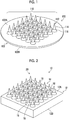
- Fig. 1 is a perspective view illustrating an example of a microneedle array 100 manufactured using a plate precursor described later.
- the microneedle array 100 of the embodiment corresponds to a patch for one administration (one patch).
- the microneedle array 100 includes a sheet-like base portion 102 having a first surface 102A and a second surface 102B, which oppose each other, and a protruding pattern 110.
- sheet-like means a thin flat shape as a whole with respect to the two opposed first and second surfaces 102A and 102B having a large area, and it is not necessary that the first surface 102A and the second surface 102B are perfectly flat.
- the base portion 102 illustrated in Fig. 1 is circular in a plan view, the base portion 102 may be rectangular, polygonal, elliptical, or the like.
- the protruding pattern 110 is constituted by a plurality of needle-like protrusions 112 (microneedles) configured to contain a drug.
- the needle-like protrusions 112 are provided on the first surface 102A.
- the needle-like protrusion 112 includes a needle portion 114 and a frustum portion 116.
- the needle portion 114 and the frustum portion 116 constituting the needle-like protrusion 112 are arranged in the order of the frustum portion 116 and the needle portion 114 from the base portion 102.
- a plurality of the frustum portions 116 are disposed on the first surface 102A of the microneedle array 100.
- the frustum portion 116 has two bottom surfaces and has a three-dimensional structure surrounded by a conical surface.
- the bottom surface (lower bottom surface) of the two bottom surfaces of the frustum portion 116 having a large area is connected to the base portion 102.
- the bottom surface (upper bottom surface) of the two bottom surfaces of the frustum portion 116 having a small area is connected to the needle portion 114.
- the area of the bottom surface in a direction away from the base portion 102 is small.
- the inclination angle (frustum portion angle) of the surface of the frustum portion 116 with respect to the first surface 102A is different from the inclination angle (needle portion angle) of the surface of the needle portion 114 with respect to the first surface 102A.
- the needle portion angle is greater than the frustum portion angle.
- the needle portion angle and the frustum portion angle are appropriately determined according to the shape of the needle-like protrusion 112 to be formed.
- the needle portion 114 has a bottom surface with a large area and a shape having a narrowest area at the distal end apart from the bottom surface. Since the bottom surface of the needle portion 114 having a large area is connected to the upper bottom surface of the frustum portion 116, the needle portion 114 has a tapered shape in a direction away from the frustum portion 116.
- the needle-like protrusion 112 constituted by the needle portion 114 and the frustum portion 116 has a tapered shape as a whole from the base portion 102 toward the distal end.
- the plurality of, for example, 4 to 2500 needle-like protrusions 112 are provided on the base portion 102. However, the number of needle-like protrusions 112 is not limited thereto.
- the frustum portion 116 has a truncated cone shape
- the needle portion 114 has a cone shape.
- the shape of the distal end of the needle portion 114 can be appropriately changed to a curved surface having a radius of curvature of 0.01 ⁇ m or more and 50 ⁇ m or less, a flat surface, or the like according to the degree of insertion of the needle portion 114 into the skin.
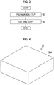
- Fig. 2 is a perspective view of the plate precursor used to manufacture (mold) the microneedle array 100.
- a plate precursor 10 has a base portion 12 having a rectangular parallelepiped shape.
- the base portion 12 has at least a first surface 12A and a second surface 12B which oppose each other.
- a plurality of needle-like protrusions 14 are provided on the first surface 12A of the base portion 12.
- the needle-like protrusion 14 includes a needle portion 16 and a frustum portion 18.
- the needle portion 16 and the frustum portion 18 constituting the needle-like protrusion 14 are arranged in the order of the frustum portion 18 and the needle portion 16 from the base portion 12.
- the plurality of needle-like protrusions 14 constitute a protruding pattern 20.
- the needle-like protrusions 14 of the plate precursor 10 conform to the size, shape, and arrangement of the needle-like protrusions 112 of the microneedle array 100 to be manufactured. Conforming includes a case of substantially conforming. It is important for the manufacturer of the microneedle array 100 to first manufacture the plate precursor 10 having the needle-like protrusions 14 that generally conform to the shape of the needle-like protrusions 112 (microneedles) to be manufactured, within a short period of time.
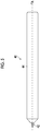
- Fig. 3 is a flowchart of the manufacturing method of the plate precursor 10 having the needle-like protrusions 14.
- the manufacturing method of the plate precursor 10 having the needle-like protrusions 14 at least includes a preparation step (step S1) and a cutting step (step S2).
- step S1 a base material and a cutting tool are prepared.
- step S2 the base material is cut by rotating and revolving the cutting tool, thereby forming needle-like protrusions.
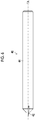
- step S1 The preparation step (step S1) will be described based on Figs. 4 to 7 .
- the base material for manufacturing the plate precursor 10 (see Fig. 2 ) having the needle-like protrusions 14 is prepared.
- a base material 30 has a rectangular parallelepiped shape.
- the base material 30 has a flat surface 30A to be cut.
- metal, cemented carbide, or ceramic can be suitably applied.
- the metal iron, aluminum, stainless steel, Ni plating, Cu plating, brass, titanium, and the like can be suitably applied.
- the material of the base material 30 is not limited to the material.
- a cutting tool 40 comprises a blade 42 and a holder 44 that holds the blade 42.
- the holder 44 is constituted by a portion having a cylindrical shape and a portion having a truncated cone shape, and the blade 42 is held by the truncated cone portion on the distal end of the holder 44.
- the cutting tool 40 is attached to a spindle (not illustrated) and can rotate about a tool axis TA.
- cemented carbide metal monocrystalline diamond, polycrystalline diamond, cubic boron nitride (CBN), or sintered diamond (polycrystalline diamond (PCD)
- CBN cubic boron nitride
- PCD sintered diamond
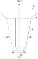
- Fig. 7 is a partial enlarged view of the cutting tool 40 in the state of Fig. 5 .
- the blade 42 is shown by solid line in Fig. 7 .
- the blade 42 has a shape that conforms to the external shape of the needle-like protrusion 14 (see Fig. 2 ).
- the blade 42 comprises a frustum blade 42A that conforms to the frustum portion 18 of the needle-like protrusion 14 and a needle blade 42B that conforms to the needle portion 16 of the needle-like protrusion 14.
- the blade 42 has a bottom surface blade 42C at its distal end.
- the bottom surface blade 42C forms the first surface 12A of the plate precursor 10.
- the first surface 12A is a reference surface that determines the height of the needle-like protrusions 14.
- two-dot chain line indicates the trajectory of the blade 42 in a case where the blade 42 is rotated about the tool axis TA.
- a first embodiment of the cutting step (step S2) will be described based on Figs. 8 to 12 .
- the cutting tool 40 and the base material 30 are aligned.
- a distance r1 between the tool axis TA of the cutting tool 40 and an axis NA of the needle-like protrusion 14 to be formed on the base material 30 is adjusted.
- the cutting tool 40 and the base material 30 are moved relative to each other to a position where the cutting tool 40 and the base material 30 come into contact with each other while maintaining a state where the tool axis TA and the axis NA are parallel (or the tool axis TA and the normal to the flat surface 30A are parallel).
- the cutting tool 40 rotates about the tool axis TA.
- the cutting tool 40 revolves around the axis NA, with the distance r1 as the revolution radius.
- the blade 42 of the cutting tool 40 cuts the flat surface 30A of the base material 30.
- the cutting tool 40 moves to the inside of the base material 30 to a predetermined depth d1.
- the cutting tool 40 performs machining on the distal end of the needle-like protrusion 14.
- the cutting tool 40 moves in a direction away from the axis NA until a distance r2 between the tool axis TA and the axis NA is reached.
- the cutting tool 40 rotates about the tool axis TA.
- the cutting tool 40 revolves around the axis NA with the distance r2 as the revolution radius.
- the blade 42 of the cutting tool 40 cuts the inside of the base material 30.
- the cutting tool 40 moves parallel to the tool axis TA toward the inside of the base material 30 stepwise to a predetermined depth d2 (the height of the needle-like protrusion 14).
- the needle-like protrusion 14 having a shape conforming to the shape of the cutting tool 40 is formed.
- the frustum blade 42A of the blade 42 forms the shape of the frustum portion 18 of the needle-like protrusion 14.
- the needle blade 42B of the blade 42 forms the shape of the needle portion 16 of the needle-like protrusion 14.
- the bottom surface blade 42C of the blade 42 forms the shape of the first surface 12A of the plate precursor 10.
- the cutting tool 40 moves to the inside of the base material 30 spirally, that is, continuously about the axis NA.
- the cutting tool 40 moves while maintaining the angle of the tool axis TA in a case of contacting the base material 30, that is, moves parallel to the tool axis TA.
- the cutting tool 40 moves in a direction away from the base material 30 in a case where the formation of the needle-like protrusion 14 is finished.
- the cutting tool 40 moves to a position where the axis NA of the needle-like protrusion 14 to be formed next and the tool axis TA are at the distance r1.
- the cutting tool 40 repeats the operations of Figs. 9 and 10 described above until the required number of needle-like protrusions 14 are formed.
- the use of the cutting tool 40 makes it possible to manufacture the plate precursor 10 having the needle-like protrusions 14 within a short period of time.
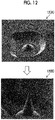
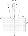
- Fig. 12 is a micrograph showing the cutting step of the needle-like protrusion 14 formed on the base material 30.
- A) of Fig. 12 is a micrograph during the formation of the needle-like protrusion.
- A) of Fig. 12 corresponds to Fig. 9 described above.
- B) of Fig. 12 is a micrograph of the needle-like protrusion.
- B) of Fig. 12 corresponds to Fig. 10 described above.
- the needle-like protrusion can be formed on the base material by the cutting tool.
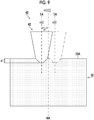
- step S2 a second embodiment of the cutting step (step S2) will be described based on Figs. 13 to 17 .
- the cutting tool 40 and the base material 30 are moved relative to each other to a position where the cutting tool 40 and the base material 30 come into contact with each other while maintaining a state where the tool axis TA and the axis NA are parallel.
- the cutting tool 40 rotates about the tool axis TA.
- the cutting tool 40 revolves around the axis NA, with the distance r1 as the revolution radius.
- the blade 42 of the cutting tool 40 cuts the flat surface 30A of the base material 30.
- the cutting tool 40 moves to the inside of the base material 30 to a predetermined depth d1.
- Fig. 13 of the second embodiment is the same as Fig. 9 of the first embodiment.
- the cutting tool 40 moves in a direction away from the axis NA until the distance r2 between the tool axis TA and the axis NA is reached.
- the cutting tool 40 rotates about the tool axis TA.
- the cutting tool 40 moves linearly to the inside of the base material 30 from the depth d1 to the predetermined depth d2.
- the cutting tool 40 moves to the inside of the base material 30 stepwise to the depth d2.
- the depth d2 is less than the height of the needle-like protrusion 14.
- the cutting tool 40 revolves around the axis NA with the distance r2 as the revolution radius.
- the blade 42 of the cutting tool 40 cuts the inside of the base material 30.
- the cutting tool 40 stops moving to the inside of the base material 30 at the depth d2.
- the cutting tool 40 moves linearly to the inside of the base material 30 from the depth d2 to a predetermined depth d3.
- the cutting tool 40 moves to the inside of the base material 30 stepwise to the depth d3.
- the depth d3 is less than the height of the needle-like protrusion 14.
- the cutting tool 40 revolves around the axis NA with the distance r2 as the revolution radius.
- the blade 42 of the cutting tool 40 cuts the inside of the base material 30.
- the cutting tool 40 stops moving to the inside of the base material 30 at the depth d3.
- the cutting tool 40 moves linearly to the inside of the base material 30 from the depth d3 to a predetermined depth d4.
- the cutting tool 40 moves to the inside of the base material 30 stepwise to the depth d4.
- the depth d4 is coincident with the height of the needle-like protrusion 14.
- the cutting tool 40 revolves around the axis NA with the distance r2 as the revolution radius.
- the blade 42 of the cutting tool 40 cuts the inside of the base material 30.
- the needle-like protrusion 14 having a shape conforming to the shape of the cutting tool 40 is formed.
- the frustum blade 42A of the blade 42 forms the shape of the frustum portion 18 of the needle-like protrusion 14.
- the needle blade 42B of the blade 42 forms the shape of the needle portion 16 of the needle-like protrusion 14.
- the bottom surface blade 42C of the blade 42 forms the shape of the first surface 12A of the plate precursor 10.
- the stepwise movement of the cutting tool 40 is an intermittent movement.
- the intermittent movement of the cutting tool 40 can suppress the deformation of the needle-like protrusion 14 during cutting.
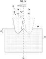
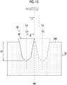
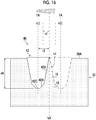
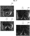
- Fig. 17 is a micrograph showing the cutting step of the needle-like protrusion formed on the base material.
- (A) of Fig. 17 , (B) of Fig. 17 , and (C) of Fig. 17 are micrographs during the formation of the needle-like protrusion.
- (A) of Fig. 17 corresponds to Fig. 13 described above.
- (B) of Fig. 17 corresponds to Fig. 14 described above.
- (C) of Fig. 17 corresponds to Fig. 15 described above.
- (D) of Fig. 17 is a micrograph of the needle-like protrusion.
- (D) of Fig. 17 corresponds to Fig. 16 described above.
- the needle-like protrusion can be formed on the base material by the cutting tool.
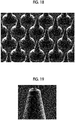
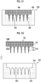
- Fig. 18 is a micrograph of a plurality of the needle-like protrusions 14 formed on the base material.
- the plurality of needle-like protrusions can be formed by repeating the above-described cutting step (step S2) a plurality of times.
- the use of the cutting tool makes it possible to manufacture the plate precursor having the plurality of needle-like protrusions within a short period of time.
- the needle-like protrusion has the frustum portion conforming to the frustum portion of the blade and the needle portion conforming to the needle blade of the blade.
- the first surface of the base portion excluding the needle-like protrusion is machined flat so as to conform to the bottom surface blade of the blade.
- Figs. 19 to 21 are enlarged micrographs of the distal end of the needle-like protrusion.
- Fig. 19 is an enlarged photograph of the distal end of the needle-like protrusion which is cut with the distance r2 (see Figs. 10 and 14 to 16 ) between the tool axis TA and the axis NA as the revolution radius.
- Fig. 20 is an enlarged photograph of the distal end of the needle-like protrusion which is cut with a revolution radius shorter than the distance r2 compared to Fig. 19 .
- Fig. 21 is an enlarged photograph of the distal end of the needle-like protrusion which is cut with a revolution radius longer than the distance r2 compared to Fig. 19 .
- the diameter of the distal end of the needle-like protrusion increases in the order of Fig. 20 , Fig. 19 , and Fig. 21 .
- the shape of the needle-like protrusion can be controlled by adjusting the distance between the tool axis TA and the axis NA.
- the cutting tools 40 form the needle-like protrusions 14 one by one.
- an uncut residue 50 is formed at a position deviating from the trajectory of the cutting tool 40 as indicated by surrounding circle symbol.
- the uncut residue 50 affects the shape of the microneedle array 100 (see Fig. 1 ) to be manufactured.
- the cutting tool 40 is moved between the needle-like protrusions 14, and then the bottom surface blade 42C of the cutting tool 40 cuts the uncut residue 50.
- the first surface 12A of the base portion 12 of the plate precursor 10 is machined flat.
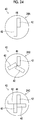
- the blade 42 of the cutting tool 40 is not limited to the above-described structure.
- the cutting tool 40 can comprise a plurality of blades 42.
- (A) of Fig. 24 illustrates a cutting tool 40 with two blades.
- the two blades 42 are held by the holder 44.
- (B) of Fig. 24 illustrates a cutting tool 40 with three blades.
- the three blades 42 are held by the holder 44.
- (C) of Fig. 24 illustrates a cutting tool 40 with four blades.
- the four blades 42 are held by the holder 44.
- the cutting tool is selected according to the shape of the needle-like protrusion to be manufactured.
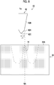
- a first posture of the cutting tool 40 indicated by two-dot chain line changes to a second posture of the cutting tool 40 indicated by solid line.
- the cutting tool 40 in the second posture cuts the base material 30.
- the change in the posture of the cutting tool 40 improves the degree of freedom of cutting and makes it possible to manufacture needle-like protrusions having a more preferable shape.
- the conditions for cutting the base material by the cutting tool are appropriately set from, for example, a feed rate of 1 mm/min to 500 mm/min, a cutting depth of 0.01 mm to 2 mm, and a rotational speed of 1000 rpm to 80,000 rpm.
- the cutting conditions are not limited thereto.
- the plate precursor 10 manufactured by the above-described manufacturing method is prepared.
- the plate precursor 10 has a size corresponding to one patch of a microneedle array.
- the plate precursor 10 has the base portion 12 and the plurality of needle-like protrusions 14.
- the needle-like protrusion 14 has the frustum portion 18 and the needle portion 16.
- the plate precursor 10 is pressed against a resin precursor 200 having a plurality of recessed portions 202 by an imprint method.
- a plurality of needle-like recessed portions 204 which are inverted shapes of the needle-like protrusions 14 of the plate precursor 10 are formed in the resin precursor 200.
- the imprint method the plate precursor 10 which is heated is pressed against the resin precursor 200.
- the plate precursor 10 is separated from the resin precursor 200.
- the resin precursor 200 is cooled, and the needle-like recessed portions 204 are formed.
- a duplicate mold 210 having a plurality of needle-like protrusions 212 is produced by electroforming.
- the resin precursor 200 is subjected to a conduction treatment.
- a metal for example, nickel
- a metal is sputtered onto the resin precursor 200, and the metal adheres to the surface of the resin precursor 200 and the needle-like recessed portions 204.
- the resin precursor 200 subjected to the conduction treatment is held by the cathode of an electroforming apparatus (not illustrated).
- a metal case holding metal pellets is the anode.
- the cathode holding the resin precursor 200 and the anode holding the metal pellets are immersed in an electroforming liquid.
- the metal is embedded in the needle-like recessed portions 204 of the resin precursor 200.
- the duplicate mold 210 having the plurality of needle-like protrusions 212 is produced by being peeled off from the resin precursor 200.
- a resin mold 220 having a plurality of needle-like recessed portions 222 is produced from the duplicate mold 210.
- the resin mold 220 can be produced, for example, by pouring a medical grade silicone material (for example, MDX4-4210 manufactured by Dow Corning) into the duplicate mold 210, performing a heating treatment thereon at 150°C so as to be cured, and thereafter peeling off the resin mold 220 from the duplicate mold 210.
- a medical grade silicone material for example, MDX4-4210 manufactured by Dow Corning
- the resin mold 220 can be produced by pouring a UV-curable resin, which is cured by being irradiated with ultraviolet light, into the duplicate mold 210, and irradiating the UV-curable resin with ultraviolet light in a nitrogen atmosphere, and thereafter peeling off the resin mold 220 from the duplicate mold 210.
- the resin mold 220 can be produced by pouring a plastic resin such as polystyrene and polymethyl methacrylate (PMMA) dissolved in an organic solvent into the duplicate mold 210 coated with a release agent, drying and curing the resultant by volatilizing the organic solvent, and thereafter peeling off the resin mold 220 from the duplicate mold 210. Therefore, the resin mold 220 having the plurality of needle-like recessed portions 222 corresponding to the plurality of needle-like protrusions 212 of the duplicate mold 210 is produced.
- a plastic resin such as polystyrene and polymethyl methacrylate (PMMA) dissolved in an organic solvent
- PMMA polymethyl methacrylate
- the resin mold 220 is cut for each of the plurality of needle-like recessed portions 222 corresponding to one patch of the microneedle array.
- the needle-like recessed portion 222 of the resin mold 220 is an inverted mold of the needle-like protrusion 14 (not illustrated) of the plate precursor 10.
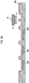
- a liquid material 300 is supplied to the resin mold 220.
- the liquid material 300 is repelled by a stepped portion 224 of the resin mold 220 and is shrunk by surface tension.
- the liquid material 300 is fixed (also referred to as pinned) at the corner on the inner diameter side of the stepped portion 224.
- suction is preferably performed from the side opposite to the side on which the liquid material 300 is placed.
- the liquid material 300 (not illustrated) is dried, and the microneedle array 100 is formed on the resin mold 220.
- the microneedle array 100 having a desired shape can be formed even after drying.
- the microneedle array 100 is separated from the resin mold 220.
- the separation method is not particularly limited.
- the microneedle array 100 is separated from the resin mold 220 by adsorbing the second surface 102B of the microneedle array 100 with a suction pad (not illustrated) and moving the suction pad in a direction away from the resin mold 220.
- the microneedle array 100 is formed by filling the needle-like recessed portion 222 by supplying the liquid material 300 to a region surrounded by the stepped portion 224 of the resin mold 220, and drying the resultant is described, but is not limited thereto.
- a drug layer can be formed on the distal end side of the needle-like recessed portion 222 before the liquid material 300 is supplied.
- the liquid material 300 containing no drug can be supplied and dried to manufacture the microneedle array 100 having the two-layer structure.
- the solidified drug layer can suppress diffusion of the drug layer to the liquid material 300.
- a polymer solution is preferable as the liquid material 300.
- the material of the polymer solution it is preferable to use a water-soluble material.
- a material of a resin polymer of the polymer solution it is preferable to use a biocompatible resin.
- resins sugars such as glucose, maltose, pullulan, sodium chondroitin sulfate, sodium hyaluronate, and hydroxyethyl starch, proteins such as gelatin, and biodegradable polymers such as polylactic acid and a lactic acid-glycolic acid copolymer are preferably used.
- the microneedle array 100 is released from the resin mold 220, since the microneedle array 100 can be released using the base material (not illustrated), such resins can be suitably used.
- a concentration varies depending on the material, it is preferable that the concentration is set so that the resin polymer is contained at 10 to 50 mass% in the polymer solution which does not contain a drug.
- a solvent used in the polymer solution may be water or may be volatile, and alcohol such as ethanol or the like may be used.
- the above-mentioned polymer solution containing a predetermined amount of drug can be applied as the liquid material for forming the drug layer. Whether or not a predetermined amount of drug is contained is determined by whether or not the drug effect can be exhibited in a case where the body surface is punctured. Therefore, containing a predetermined amount of drug means containing a drug in an amount that exhibits the drug effect in a case where the body surface is punctured.
- the drug is not limited as long as the drug has a function as a drug.
- the drug is preferably selected from peptides, proteins, nucleic acids, polysaccharides, vaccines, pharmaceutical compounds that belong to a water-soluble low molecular weight compound, or cosmetic ingredients.
- the manufacturing method of the second microneedle array is different from the manufacturing method of the first microneedle array in that a resin mold is produced from a plate precursor.
- a resin mold is produced from a plate precursor.
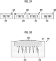
- a large plate precursor 60 having a size corresponding to a plurality of patches of the microneedle array is prepared.
- the large plate precursor 60 has a plurality of the needle-like protrusions 14 for each size corresponding to one patch of the microneedle array.
- the resin mold 220 having a plurality of the needle-like recessed portions 222 is produced from the large plate precursor 60.
- the resin mold 220 can be produced, for example, by pouring a medical grade silicone material (for example, MDX4-4210 manufactured by Dow Corning) into the duplicate mold 210, performing a heating treatment thereon at 150°C so as to be cured, and thereafter peeling off the resin mold 220 from the large plate precursor 60.
- the resin mold 220 can be produced from the large plate precursor 60 using the other method described in Fig. 28 .
- the large plate precursor 60 can be produced within a short period of time by using the cutting tool 40.
- steps of producing a resin precursor and a duplicate mold can be omitted.
Landscapes
- Engineering & Computer Science (AREA)
- Health & Medical Sciences (AREA)
- Mechanical Engineering (AREA)
- Manufacturing & Machinery (AREA)
- Life Sciences & Earth Sciences (AREA)
- Biomedical Technology (AREA)
- Heart & Thoracic Surgery (AREA)
- Hematology (AREA)
- Anesthesiology (AREA)
- Animal Behavior & Ethology (AREA)
- General Health & Medical Sciences (AREA)
- Public Health (AREA)
- Veterinary Medicine (AREA)
- Medical Informatics (AREA)
- Dermatology (AREA)
- Media Introduction/Drainage Providing Device (AREA)
Applications Claiming Priority (1)
| Application Number | Priority Date | Filing Date | Title |
|---|---|---|---|
| JP2018194095A JP6985233B2 (ja) | 2018-10-15 | 2018-10-15 | 針状突起を有する原版の製造方法、及びマイクロニードルアレイの製造方法 |
Publications (2)
| Publication Number | Publication Date |
|---|---|
| EP3646919A1 EP3646919A1 (en) | 2020-05-06 |
| EP3646919B1 true EP3646919B1 (en) | 2020-12-16 |
Family
ID=68109186
Family Applications (1)
| Application Number | Title | Priority Date | Filing Date |
|---|---|---|---|
| EP19200753.2A Active EP3646919B1 (en) | 2018-10-15 | 2019-10-01 | Manufacturing method of plate precursor having needle-like protrusion, and manufacturing method of microneedle array |
Country Status (4)
| Country | Link |
|---|---|
| US (1) | US11597122B2 (enExample) |
| EP (1) | EP3646919B1 (enExample) |
| JP (1) | JP6985233B2 (enExample) |
| CN (1) | CN111035849B (enExample) |
Families Citing this family (3)
| Publication number | Priority date | Publication date | Assignee | Title |
|---|---|---|---|---|
| JP7038679B2 (ja) * | 2019-03-05 | 2022-03-18 | 富士フイルム株式会社 | 熱可塑性樹脂原版の作製方法、金型の作製方法、モールドの作製方法及びパターンシートの製造方法 |
| CN112569465B (zh) * | 2020-12-29 | 2022-07-19 | 华东理工大学 | 一种微针贴片的制备方法 |
| GB2622416B (en) * | 2022-09-15 | 2025-04-02 | Ndm Tech Ltd | Skin preparation device |
Family Cites Families (15)
| Publication number | Priority date | Publication date | Assignee | Title |
|---|---|---|---|---|
| JPS541061B2 (enExample) | 1973-03-14 | 1979-01-19 | ||
| WO2005044364A1 (en) | 2003-11-10 | 2005-05-19 | Agency For Science, Technology And Research | Microneedles and microneedle fabrication |
| JP3945716B2 (ja) * | 2005-12-14 | 2007-07-18 | インターナショナル・ビジネス・マシーンズ・コーポレーション | エンドミルとその製造方法 |
| WO2008013282A1 (fr) * | 2006-07-27 | 2008-01-31 | Toppan Printing Co., Ltd. | Procédé de production d'une micro-aiguille |
| JP2008114345A (ja) * | 2006-11-07 | 2008-05-22 | Toppan Printing Co Ltd | 微細で鋭利な針状構造の規則配列体、及びその複製物の製造方法 |
| JP2008237673A (ja) | 2007-03-28 | 2008-10-09 | Toppan Printing Co Ltd | 針状体およびその製造方法 |
| JP5401061B2 (ja) * | 2008-09-04 | 2014-01-29 | 凸版印刷株式会社 | 針状体製造方法、および研削刃 |
| JP5568324B2 (ja) * | 2010-01-15 | 2014-08-06 | 凸版印刷株式会社 | マイクロニードル製造方法 |
| US20130096532A1 (en) * | 2011-10-17 | 2013-04-18 | Rutgers, The State University Of New Jersey | Polymer-Based Micro-Needle Array Designs, Fabrication Processes, and Methods of Use Thereof for Drug Delivery |
| JP6662296B2 (ja) | 2014-11-07 | 2020-03-11 | 凸版印刷株式会社 | 経皮投薬用針集成体及びその製造方法 |
| JP6482323B2 (ja) * | 2015-03-03 | 2019-03-13 | 富士フイルム株式会社 | 経皮吸収シート |
| WO2017056894A1 (ja) * | 2015-09-30 | 2017-04-06 | 富士フイルム株式会社 | モールドの作製方法、パターンシートの製造方法、電鋳金型の作製方法、及び電鋳金型を用いたモールドの作製方法 |
| JP6587345B2 (ja) * | 2015-10-06 | 2019-10-09 | 富士フイルム株式会社 | 樹脂製モールドの作製方法 |
| JP6533189B2 (ja) * | 2016-05-24 | 2019-06-19 | 富士フイルム株式会社 | パターンアレイシート成形用型の製造方法、及びマイクロニードルアレイの製造方法 |
| JP2018042677A (ja) * | 2016-09-13 | 2018-03-22 | 富士フイルム株式会社 | 凹状パターンモールドおよびパターンシートの製造方法 |
-
2018
- 2018-10-15 JP JP2018194095A patent/JP6985233B2/ja active Active
-
2019
- 2019-10-01 EP EP19200753.2A patent/EP3646919B1/en active Active
- 2019-10-03 US US16/591,634 patent/US11597122B2/en active Active
- 2019-10-12 CN CN201910965740.1A patent/CN111035849B/zh active Active
Non-Patent Citations (1)
| Title |
|---|
| None * |
Also Published As
| Publication number | Publication date |
|---|---|
| EP3646919A1 (en) | 2020-05-06 |
| JP2020062078A (ja) | 2020-04-23 |
| US11597122B2 (en) | 2023-03-07 |
| JP6985233B2 (ja) | 2021-12-22 |
| CN111035849A (zh) | 2020-04-21 |
| US20200114547A1 (en) | 2020-04-16 |
| CN111035849B (zh) | 2023-03-28 |
Similar Documents
| Publication | Publication Date | Title |
|---|---|---|
| EP3646919B1 (en) | Manufacturing method of plate precursor having needle-like protrusion, and manufacturing method of microneedle array | |
| EP3705254B1 (en) | Production method of mold having recessed pattern in recessed step portion, and manufacturing method of pattern sheet | |
| CN107922183B (zh) | 铸模的制作方法、图案片材的制造方法、电铸模具的制作方法及使用了电铸模具的铸模的制作方法 | |
| CN108138344B (zh) | 经皮吸收片材的制造方法 | |
| JP2013153866A (ja) | 経皮吸収シート及び経皮吸収シートの製造方法 | |
| JP2008237673A (ja) | 針状体およびその製造方法 | |
| AU2020200063B2 (en) | Method for fabricating mold having recessed pattern and method for producing patterned sheet | |
| CN104755129B (zh) | 针状构造体及其制造方法 | |
| CN112839698B (zh) | 经皮吸收片材的制造方法 | |
| JP6533189B2 (ja) | パターンアレイシート成形用型の製造方法、及びマイクロニードルアレイの製造方法 | |
| JP5173331B2 (ja) | 針状体チップおよびその製造方法 | |
| CN112569465B (zh) | 一种微针贴片的制备方法 | |
| JP7457732B2 (ja) | マイクロニードルアレイの製造方法 | |
| WO2020067102A1 (ja) | モールド、及び、経皮吸収シートの製造方法 | |
| JP2009240409A (ja) | 針状体アレイおよびそのアレイ製造方法 | |
| JP6476799B2 (ja) | 針状体の製造方法 | |
| EP3778169A1 (en) | Method for manufacturing mold having concave pedestal pattern and method for manufacturing pattern sheet | |
| JP5205016B2 (ja) | 針状体、針状体製造方法 | |
| JP2009233793A (ja) | 針状体ならびに複製針状体の製造方法および針状体の製造装置 | |
| JP2009078071A (ja) | 針状体機器 |
Legal Events
| Date | Code | Title | Description |
|---|---|---|---|
| PUAI | Public reference made under article 153(3) epc to a published international application that has entered the european phase |
Free format text: ORIGINAL CODE: 0009012 |
|
| STAA | Information on the status of an ep patent application or granted ep patent |
Free format text: STATUS: THE APPLICATION HAS BEEN PUBLISHED |
|
| AK | Designated contracting states |
Kind code of ref document: A1 Designated state(s): AL AT BE BG CH CY CZ DE DK EE ES FI FR GB GR HR HU IE IS IT LI LT LU LV MC MK MT NL NO PL PT RO RS SE SI SK SM TR |
|
| AX | Request for extension of the european patent |
Extension state: BA ME |
|
| STAA | Information on the status of an ep patent application or granted ep patent |
Free format text: STATUS: REQUEST FOR EXAMINATION WAS MADE |
|
| 17P | Request for examination filed |
Effective date: 20200623 |
|
| RBV | Designated contracting states (corrected) |
Designated state(s): AL AT BE BG CH CY CZ DE DK EE ES FI FR GB GR HR HU IE IS IT LI LT LU LV MC MK MT NL NO PL PT RO RS SE SI SK SM TR |
|
| GRAP | Despatch of communication of intention to grant a patent |
Free format text: ORIGINAL CODE: EPIDOSNIGR1 |
|
| STAA | Information on the status of an ep patent application or granted ep patent |
Free format text: STATUS: GRANT OF PATENT IS INTENDED |
|
| INTG | Intention to grant announced |
Effective date: 20200817 |
|
| GRAS | Grant fee paid |
Free format text: ORIGINAL CODE: EPIDOSNIGR3 |
|
| GRAA | (expected) grant |
Free format text: ORIGINAL CODE: 0009210 |
|
| STAA | Information on the status of an ep patent application or granted ep patent |
Free format text: STATUS: THE PATENT HAS BEEN GRANTED |
|
| AK | Designated contracting states |
Kind code of ref document: B1 Designated state(s): AL AT BE BG CH CY CZ DE DK EE ES FI FR GB GR HR HU IE IS IT LI LT LU LV MC MK MT NL NO PL PT RO RS SE SI SK SM TR |
|
| REG | Reference to a national code |
Ref country code: GB Ref legal event code: FG4D |
|
| REG | Reference to a national code |
Ref country code: IE Ref legal event code: FG4D |
|
| REG | Reference to a national code |
Ref country code: DE Ref legal event code: R096 Ref document number: 602019001773 Country of ref document: DE |
|
| REG | Reference to a national code |
Ref country code: AT Ref legal event code: REF Ref document number: 1345039 Country of ref document: AT Kind code of ref document: T Effective date: 20210115 |
|
| RAP4 | Party data changed (patent owner data changed or rights of a patent transferred) |
Owner name: FUJIFILM CORPORATION |
|
| PG25 | Lapsed in a contracting state [announced via postgrant information from national office to epo] |
Ref country code: FI Free format text: LAPSE BECAUSE OF FAILURE TO SUBMIT A TRANSLATION OF THE DESCRIPTION OR TO PAY THE FEE WITHIN THE PRESCRIBED TIME-LIMIT Effective date: 20201216 Ref country code: RS Free format text: LAPSE BECAUSE OF FAILURE TO SUBMIT A TRANSLATION OF THE DESCRIPTION OR TO PAY THE FEE WITHIN THE PRESCRIBED TIME-LIMIT Effective date: 20201216 Ref country code: GR Free format text: LAPSE BECAUSE OF FAILURE TO SUBMIT A TRANSLATION OF THE DESCRIPTION OR TO PAY THE FEE WITHIN THE PRESCRIBED TIME-LIMIT Effective date: 20210317 Ref country code: NO Free format text: LAPSE BECAUSE OF FAILURE TO SUBMIT A TRANSLATION OF THE DESCRIPTION OR TO PAY THE FEE WITHIN THE PRESCRIBED TIME-LIMIT Effective date: 20210316 |
|
| REG | Reference to a national code |
Ref country code: AT Ref legal event code: MK05 Ref document number: 1345039 Country of ref document: AT Kind code of ref document: T Effective date: 20201216 |
|
| REG | Reference to a national code |
Ref country code: NL Ref legal event code: MP Effective date: 20201216 |
|
| PG25 | Lapsed in a contracting state [announced via postgrant information from national office to epo] |
Ref country code: LV Free format text: LAPSE BECAUSE OF FAILURE TO SUBMIT A TRANSLATION OF THE DESCRIPTION OR TO PAY THE FEE WITHIN THE PRESCRIBED TIME-LIMIT Effective date: 20201216 Ref country code: SE Free format text: LAPSE BECAUSE OF FAILURE TO SUBMIT A TRANSLATION OF THE DESCRIPTION OR TO PAY THE FEE WITHIN THE PRESCRIBED TIME-LIMIT Effective date: 20201216 Ref country code: BG Free format text: LAPSE BECAUSE OF FAILURE TO SUBMIT A TRANSLATION OF THE DESCRIPTION OR TO PAY THE FEE WITHIN THE PRESCRIBED TIME-LIMIT Effective date: 20210316 |
|
| PG25 | Lapsed in a contracting state [announced via postgrant information from national office to epo] |
Ref country code: HR Free format text: LAPSE BECAUSE OF FAILURE TO SUBMIT A TRANSLATION OF THE DESCRIPTION OR TO PAY THE FEE WITHIN THE PRESCRIBED TIME-LIMIT Effective date: 20201216 Ref country code: NL Free format text: LAPSE BECAUSE OF FAILURE TO SUBMIT A TRANSLATION OF THE DESCRIPTION OR TO PAY THE FEE WITHIN THE PRESCRIBED TIME-LIMIT Effective date: 20201216 |
|
| REG | Reference to a national code |
Ref country code: LT Ref legal event code: MG9D |
|
| PG25 | Lapsed in a contracting state [announced via postgrant information from national office to epo] |
Ref country code: EE Free format text: LAPSE BECAUSE OF FAILURE TO SUBMIT A TRANSLATION OF THE DESCRIPTION OR TO PAY THE FEE WITHIN THE PRESCRIBED TIME-LIMIT Effective date: 20201216 Ref country code: SK Free format text: LAPSE BECAUSE OF FAILURE TO SUBMIT A TRANSLATION OF THE DESCRIPTION OR TO PAY THE FEE WITHIN THE PRESCRIBED TIME-LIMIT Effective date: 20201216 Ref country code: SM Free format text: LAPSE BECAUSE OF FAILURE TO SUBMIT A TRANSLATION OF THE DESCRIPTION OR TO PAY THE FEE WITHIN THE PRESCRIBED TIME-LIMIT Effective date: 20201216 Ref country code: CZ Free format text: LAPSE BECAUSE OF FAILURE TO SUBMIT A TRANSLATION OF THE DESCRIPTION OR TO PAY THE FEE WITHIN THE PRESCRIBED TIME-LIMIT Effective date: 20201216 Ref country code: LT Free format text: LAPSE BECAUSE OF FAILURE TO SUBMIT A TRANSLATION OF THE DESCRIPTION OR TO PAY THE FEE WITHIN THE PRESCRIBED TIME-LIMIT Effective date: 20201216 Ref country code: PT Free format text: LAPSE BECAUSE OF FAILURE TO SUBMIT A TRANSLATION OF THE DESCRIPTION OR TO PAY THE FEE WITHIN THE PRESCRIBED TIME-LIMIT Effective date: 20210416 Ref country code: RO Free format text: LAPSE BECAUSE OF FAILURE TO SUBMIT A TRANSLATION OF THE DESCRIPTION OR TO PAY THE FEE WITHIN THE PRESCRIBED TIME-LIMIT Effective date: 20201216 |
|
| PG25 | Lapsed in a contracting state [announced via postgrant information from national office to epo] |
Ref country code: AT Free format text: LAPSE BECAUSE OF FAILURE TO SUBMIT A TRANSLATION OF THE DESCRIPTION OR TO PAY THE FEE WITHIN THE PRESCRIBED TIME-LIMIT Effective date: 20201216 Ref country code: PL Free format text: LAPSE BECAUSE OF FAILURE TO SUBMIT A TRANSLATION OF THE DESCRIPTION OR TO PAY THE FEE WITHIN THE PRESCRIBED TIME-LIMIT Effective date: 20201216 |
|
| REG | Reference to a national code |
Ref country code: DE Ref legal event code: R097 Ref document number: 602019001773 Country of ref document: DE |
|
| PG25 | Lapsed in a contracting state [announced via postgrant information from national office to epo] |
Ref country code: IS Free format text: LAPSE BECAUSE OF FAILURE TO SUBMIT A TRANSLATION OF THE DESCRIPTION OR TO PAY THE FEE WITHIN THE PRESCRIBED TIME-LIMIT Effective date: 20210416 |
|
| PLBE | No opposition filed within time limit |
Free format text: ORIGINAL CODE: 0009261 |
|
| STAA | Information on the status of an ep patent application or granted ep patent |
Free format text: STATUS: NO OPPOSITION FILED WITHIN TIME LIMIT |
|
| PG25 | Lapsed in a contracting state [announced via postgrant information from national office to epo] |
Ref country code: AL Free format text: LAPSE BECAUSE OF FAILURE TO SUBMIT A TRANSLATION OF THE DESCRIPTION OR TO PAY THE FEE WITHIN THE PRESCRIBED TIME-LIMIT Effective date: 20201216 Ref country code: IT Free format text: LAPSE BECAUSE OF FAILURE TO SUBMIT A TRANSLATION OF THE DESCRIPTION OR TO PAY THE FEE WITHIN THE PRESCRIBED TIME-LIMIT Effective date: 20201216 |
|
| 26N | No opposition filed |
Effective date: 20210917 |
|
| PG25 | Lapsed in a contracting state [announced via postgrant information from national office to epo] |
Ref country code: DK Free format text: LAPSE BECAUSE OF FAILURE TO SUBMIT A TRANSLATION OF THE DESCRIPTION OR TO PAY THE FEE WITHIN THE PRESCRIBED TIME-LIMIT Effective date: 20201216 |
|
| PG25 | Lapsed in a contracting state [announced via postgrant information from national office to epo] |
Ref country code: ES Free format text: LAPSE BECAUSE OF FAILURE TO SUBMIT A TRANSLATION OF THE DESCRIPTION OR TO PAY THE FEE WITHIN THE PRESCRIBED TIME-LIMIT Effective date: 20201216 |
|
| PG25 | Lapsed in a contracting state [announced via postgrant information from national office to epo] |
Ref country code: SI Free format text: LAPSE BECAUSE OF FAILURE TO SUBMIT A TRANSLATION OF THE DESCRIPTION OR TO PAY THE FEE WITHIN THE PRESCRIBED TIME-LIMIT Effective date: 20201216 |
|
| PG25 | Lapsed in a contracting state [announced via postgrant information from national office to epo] |
Ref country code: IS Free format text: LAPSE BECAUSE OF FAILURE TO SUBMIT A TRANSLATION OF THE DESCRIPTION OR TO PAY THE FEE WITHIN THE PRESCRIBED TIME-LIMIT Effective date: 20210416 |
|
| REG | Reference to a national code |
Ref country code: BE Ref legal event code: MM Effective date: 20211031 |
|
| PG25 | Lapsed in a contracting state [announced via postgrant information from national office to epo] |
Ref country code: MC Free format text: LAPSE BECAUSE OF FAILURE TO SUBMIT A TRANSLATION OF THE DESCRIPTION OR TO PAY THE FEE WITHIN THE PRESCRIBED TIME-LIMIT Effective date: 20201216 |
|
| PG25 | Lapsed in a contracting state [announced via postgrant information from national office to epo] |
Ref country code: LU Free format text: LAPSE BECAUSE OF NON-PAYMENT OF DUE FEES Effective date: 20211001 Ref country code: BE Free format text: LAPSE BECAUSE OF NON-PAYMENT OF DUE FEES Effective date: 20211031 |
|
| PG25 | Lapsed in a contracting state [announced via postgrant information from national office to epo] |
Ref country code: IE Free format text: LAPSE BECAUSE OF NON-PAYMENT OF DUE FEES Effective date: 20211001 |
|
| REG | Reference to a national code |
Ref country code: CH Ref legal event code: PL |
|
| P01 | Opt-out of the competence of the unified patent court (upc) registered |
Effective date: 20230515 |
|
| PG25 | Lapsed in a contracting state [announced via postgrant information from national office to epo] |
Ref country code: CY Free format text: LAPSE BECAUSE OF FAILURE TO SUBMIT A TRANSLATION OF THE DESCRIPTION OR TO PAY THE FEE WITHIN THE PRESCRIBED TIME-LIMIT Effective date: 20201216 |
|
| PG25 | Lapsed in a contracting state [announced via postgrant information from national office to epo] |
Ref country code: LI Free format text: LAPSE BECAUSE OF NON-PAYMENT OF DUE FEES Effective date: 20221031 Ref country code: HU Free format text: LAPSE BECAUSE OF FAILURE TO SUBMIT A TRANSLATION OF THE DESCRIPTION OR TO PAY THE FEE WITHIN THE PRESCRIBED TIME-LIMIT; INVALID AB INITIO Effective date: 20191001 Ref country code: CH Free format text: LAPSE BECAUSE OF NON-PAYMENT OF DUE FEES Effective date: 20221031 |
|
| PG25 | Lapsed in a contracting state [announced via postgrant information from national office to epo] |
Ref country code: MK Free format text: LAPSE BECAUSE OF FAILURE TO SUBMIT A TRANSLATION OF THE DESCRIPTION OR TO PAY THE FEE WITHIN THE PRESCRIBED TIME-LIMIT Effective date: 20201216 |
|
| PG25 | Lapsed in a contracting state [announced via postgrant information from national office to epo] |
Ref country code: TR Free format text: LAPSE BECAUSE OF FAILURE TO SUBMIT A TRANSLATION OF THE DESCRIPTION OR TO PAY THE FEE WITHIN THE PRESCRIBED TIME-LIMIT Effective date: 20201216 |
|
| PG25 | Lapsed in a contracting state [announced via postgrant information from national office to epo] |
Ref country code: MT Free format text: LAPSE BECAUSE OF FAILURE TO SUBMIT A TRANSLATION OF THE DESCRIPTION OR TO PAY THE FEE WITHIN THE PRESCRIBED TIME-LIMIT Effective date: 20201216 |
|
| PGFP | Annual fee paid to national office [announced via postgrant information from national office to epo] |
Ref country code: DE Payment date: 20240828 Year of fee payment: 6 |
|
| PGFP | Annual fee paid to national office [announced via postgrant information from national office to epo] |
Ref country code: GB Payment date: 20250828 Year of fee payment: 7 |
|
| PGFP | Annual fee paid to national office [announced via postgrant information from national office to epo] |
Ref country code: FR Payment date: 20250908 Year of fee payment: 7 |