EP3646830B1 - Dispositif et procédé de production de stratifié étirable pour article vestimentaire - Google Patents
Dispositif et procédé de production de stratifié étirable pour article vestimentaire Download PDFInfo
- Publication number
- EP3646830B1 EP3646830B1 EP18823118.7A EP18823118A EP3646830B1 EP 3646830 B1 EP3646830 B1 EP 3646830B1 EP 18823118 A EP18823118 A EP 18823118A EP 3646830 B1 EP3646830 B1 EP 3646830B1
- Authority
- EP
- European Patent Office
- Prior art keywords
- sheet
- anvil roll
- sheets
- elastic members
- pair
- Prior art date
- Legal status (The legal status is an assumption and is not a legal conclusion. Google has not performed a legal analysis and makes no representation as to the accuracy of the status listed.)
- Active
Links
Images


Classifications
-
- A—HUMAN NECESSITIES
- A61—MEDICAL OR VETERINARY SCIENCE; HYGIENE
- A61F—FILTERS IMPLANTABLE INTO BLOOD VESSELS; PROSTHESES; DEVICES PROVIDING PATENCY TO, OR PREVENTING COLLAPSING OF, TUBULAR STRUCTURES OF THE BODY, e.g. STENTS; ORTHOPAEDIC, NURSING OR CONTRACEPTIVE DEVICES; FOMENTATION; TREATMENT OR PROTECTION OF EYES OR EARS; BANDAGES, DRESSINGS OR ABSORBENT PADS; FIRST-AID KITS
- A61F13/00—Bandages or dressings; Absorbent pads
- A61F13/15—Absorbent pads, e.g. sanitary towels, swabs or tampons for external or internal application to the body; Supporting or fastening means therefor; Tampon applicators
- A61F13/15577—Apparatus or processes for manufacturing
- A61F13/15707—Mechanical treatment, e.g. notching, twisting, compressing, shaping
- A61F13/15731—Treating webs, e.g. for giving them a fibrelike appearance, e.g. by embossing
-
- B—PERFORMING OPERATIONS; TRANSPORTING
- B29—WORKING OF PLASTICS; WORKING OF SUBSTANCES IN A PLASTIC STATE IN GENERAL
- B29C—SHAPING OR JOINING OF PLASTICS; SHAPING OF MATERIAL IN A PLASTIC STATE, NOT OTHERWISE PROVIDED FOR; AFTER-TREATMENT OF THE SHAPED PRODUCTS, e.g. REPAIRING
- B29C66/00—General aspects of processes or apparatus for joining preformed parts
- B29C66/40—General aspects of joining substantially flat articles, e.g. plates, sheets or web-like materials; Making flat seams in tubular or hollow articles; Joining single elements to substantially flat surfaces
- B29C66/41—Joining substantially flat articles ; Making flat seams in tubular or hollow articles
- B29C66/43—Joining a relatively small portion of the surface of said articles
- B29C66/433—Casing-in, i.e. enclosing an element between two sheets by an outlined seam
-
- A—HUMAN NECESSITIES
- A61—MEDICAL OR VETERINARY SCIENCE; HYGIENE
- A61F—FILTERS IMPLANTABLE INTO BLOOD VESSELS; PROSTHESES; DEVICES PROVIDING PATENCY TO, OR PREVENTING COLLAPSING OF, TUBULAR STRUCTURES OF THE BODY, e.g. STENTS; ORTHOPAEDIC, NURSING OR CONTRACEPTIVE DEVICES; FOMENTATION; TREATMENT OR PROTECTION OF EYES OR EARS; BANDAGES, DRESSINGS OR ABSORBENT PADS; FIRST-AID KITS
- A61F13/00—Bandages or dressings; Absorbent pads
- A61F13/15—Absorbent pads, e.g. sanitary towels, swabs or tampons for external or internal application to the body; Supporting or fastening means therefor; Tampon applicators
- A61F13/15577—Apparatus or processes for manufacturing
- A61F13/15585—Apparatus or processes for manufacturing of babies' napkins, e.g. diapers
- A61F13/15593—Apparatus or processes for manufacturing of babies' napkins, e.g. diapers having elastic ribbons fixed thereto; Devices for applying the ribbons
-
- A—HUMAN NECESSITIES
- A61—MEDICAL OR VETERINARY SCIENCE; HYGIENE
- A61F—FILTERS IMPLANTABLE INTO BLOOD VESSELS; PROSTHESES; DEVICES PROVIDING PATENCY TO, OR PREVENTING COLLAPSING OF, TUBULAR STRUCTURES OF THE BODY, e.g. STENTS; ORTHOPAEDIC, NURSING OR CONTRACEPTIVE DEVICES; FOMENTATION; TREATMENT OR PROTECTION OF EYES OR EARS; BANDAGES, DRESSINGS OR ABSORBENT PADS; FIRST-AID KITS
- A61F13/00—Bandages or dressings; Absorbent pads
- A61F13/15—Absorbent pads, e.g. sanitary towels, swabs or tampons for external or internal application to the body; Supporting or fastening means therefor; Tampon applicators
- A61F13/15577—Apparatus or processes for manufacturing
- A61F13/15699—Forming webs by bringing together several webs, e.g. by laminating or folding several webs, with or without additional treatment of the webs
-
- A—HUMAN NECESSITIES
- A61—MEDICAL OR VETERINARY SCIENCE; HYGIENE
- A61F—FILTERS IMPLANTABLE INTO BLOOD VESSELS; PROSTHESES; DEVICES PROVIDING PATENCY TO, OR PREVENTING COLLAPSING OF, TUBULAR STRUCTURES OF THE BODY, e.g. STENTS; ORTHOPAEDIC, NURSING OR CONTRACEPTIVE DEVICES; FOMENTATION; TREATMENT OR PROTECTION OF EYES OR EARS; BANDAGES, DRESSINGS OR ABSORBENT PADS; FIRST-AID KITS
- A61F13/00—Bandages or dressings; Absorbent pads
- A61F13/15—Absorbent pads, e.g. sanitary towels, swabs or tampons for external or internal application to the body; Supporting or fastening means therefor; Tampon applicators
- A61F13/15577—Apparatus or processes for manufacturing
- A61F13/15707—Mechanical treatment, e.g. notching, twisting, compressing, shaping
- A61F13/15739—Sealing, e.g. involving cutting
-
- A—HUMAN NECESSITIES
- A61—MEDICAL OR VETERINARY SCIENCE; HYGIENE
- A61F—FILTERS IMPLANTABLE INTO BLOOD VESSELS; PROSTHESES; DEVICES PROVIDING PATENCY TO, OR PREVENTING COLLAPSING OF, TUBULAR STRUCTURES OF THE BODY, e.g. STENTS; ORTHOPAEDIC, NURSING OR CONTRACEPTIVE DEVICES; FOMENTATION; TREATMENT OR PROTECTION OF EYES OR EARS; BANDAGES, DRESSINGS OR ABSORBENT PADS; FIRST-AID KITS
- A61F13/00—Bandages or dressings; Absorbent pads
- A61F13/15—Absorbent pads, e.g. sanitary towels, swabs or tampons for external or internal application to the body; Supporting or fastening means therefor; Tampon applicators
- A61F13/15577—Apparatus or processes for manufacturing
- A61F13/15707—Mechanical treatment, e.g. notching, twisting, compressing, shaping
- A61F13/15747—Folding; Pleating; Coiling; Stacking; Packaging
-
- A—HUMAN NECESSITIES
- A61—MEDICAL OR VETERINARY SCIENCE; HYGIENE
- A61F—FILTERS IMPLANTABLE INTO BLOOD VESSELS; PROSTHESES; DEVICES PROVIDING PATENCY TO, OR PREVENTING COLLAPSING OF, TUBULAR STRUCTURES OF THE BODY, e.g. STENTS; ORTHOPAEDIC, NURSING OR CONTRACEPTIVE DEVICES; FOMENTATION; TREATMENT OR PROTECTION OF EYES OR EARS; BANDAGES, DRESSINGS OR ABSORBENT PADS; FIRST-AID KITS
- A61F13/00—Bandages or dressings; Absorbent pads
- A61F13/15—Absorbent pads, e.g. sanitary towels, swabs or tampons for external or internal application to the body; Supporting or fastening means therefor; Tampon applicators
- A61F13/15577—Apparatus or processes for manufacturing
- A61F13/15756—Applying tabs, strips, tapes, loops; Knotting the ends of pads
-
- A—HUMAN NECESSITIES
- A61—MEDICAL OR VETERINARY SCIENCE; HYGIENE
- A61F—FILTERS IMPLANTABLE INTO BLOOD VESSELS; PROSTHESES; DEVICES PROVIDING PATENCY TO, OR PREVENTING COLLAPSING OF, TUBULAR STRUCTURES OF THE BODY, e.g. STENTS; ORTHOPAEDIC, NURSING OR CONTRACEPTIVE DEVICES; FOMENTATION; TREATMENT OR PROTECTION OF EYES OR EARS; BANDAGES, DRESSINGS OR ABSORBENT PADS; FIRST-AID KITS
- A61F13/00—Bandages or dressings; Absorbent pads
- A61F13/15—Absorbent pads, e.g. sanitary towels, swabs or tampons for external or internal application to the body; Supporting or fastening means therefor; Tampon applicators
- A61F13/15577—Apparatus or processes for manufacturing
- A61F13/15764—Transferring, feeding or handling devices; Drives
-
- A—HUMAN NECESSITIES
- A61—MEDICAL OR VETERINARY SCIENCE; HYGIENE
- A61F—FILTERS IMPLANTABLE INTO BLOOD VESSELS; PROSTHESES; DEVICES PROVIDING PATENCY TO, OR PREVENTING COLLAPSING OF, TUBULAR STRUCTURES OF THE BODY, e.g. STENTS; ORTHOPAEDIC, NURSING OR CONTRACEPTIVE DEVICES; FOMENTATION; TREATMENT OR PROTECTION OF EYES OR EARS; BANDAGES, DRESSINGS OR ABSORBENT PADS; FIRST-AID KITS
- A61F13/00—Bandages or dressings; Absorbent pads
- A61F13/15—Absorbent pads, e.g. sanitary towels, swabs or tampons for external or internal application to the body; Supporting or fastening means therefor; Tampon applicators
- A61F13/45—Absorbent pads, e.g. sanitary towels, swabs or tampons for external or internal application to the body; Supporting or fastening means therefor; Tampon applicators characterised by the shape
- A61F13/49—Absorbent pads, e.g. sanitary towels, swabs or tampons for external or internal application to the body; Supporting or fastening means therefor; Tampon applicators characterised by the shape specially adapted to be worn around the waist, e.g. diapers, nappies
- A61F13/49007—Form-fitting, self-adjusting disposable diapers
- A61F13/49009—Form-fitting, self-adjusting disposable diapers with elastic means
- A61F13/4902—Form-fitting, self-adjusting disposable diapers with elastic means characterised by the elastic material
-
- B—PERFORMING OPERATIONS; TRANSPORTING
- B29—WORKING OF PLASTICS; WORKING OF SUBSTANCES IN A PLASTIC STATE IN GENERAL
- B29C—SHAPING OR JOINING OF PLASTICS; SHAPING OF MATERIAL IN A PLASTIC STATE, NOT OTHERWISE PROVIDED FOR; AFTER-TREATMENT OF THE SHAPED PRODUCTS, e.g. REPAIRING
- B29C65/00—Joining or sealing of preformed parts, e.g. welding of plastics materials; Apparatus therefor
- B29C65/02—Joining or sealing of preformed parts, e.g. welding of plastics materials; Apparatus therefor by heating, with or without pressure
- B29C65/08—Joining or sealing of preformed parts, e.g. welding of plastics materials; Apparatus therefor by heating, with or without pressure using ultrasonic vibrations
- B29C65/083—Joining or sealing of preformed parts, e.g. welding of plastics materials; Apparatus therefor by heating, with or without pressure using ultrasonic vibrations using a rotary sonotrode or a rotary anvil
- B29C65/086—Joining or sealing of preformed parts, e.g. welding of plastics materials; Apparatus therefor by heating, with or without pressure using ultrasonic vibrations using a rotary sonotrode or a rotary anvil using a rotary anvil
-
- B—PERFORMING OPERATIONS; TRANSPORTING
- B29—WORKING OF PLASTICS; WORKING OF SUBSTANCES IN A PLASTIC STATE IN GENERAL
- B29C—SHAPING OR JOINING OF PLASTICS; SHAPING OF MATERIAL IN A PLASTIC STATE, NOT OTHERWISE PROVIDED FOR; AFTER-TREATMENT OF THE SHAPED PRODUCTS, e.g. REPAIRING
- B29C66/00—General aspects of processes or apparatus for joining preformed parts
- B29C66/01—General aspects dealing with the joint area or with the area to be joined
- B29C66/05—Particular design of joint configurations
- B29C66/10—Particular design of joint configurations particular design of the joint cross-sections
- B29C66/11—Joint cross-sections comprising a single joint-segment, i.e. one of the parts to be joined comprising a single joint-segment in the joint cross-section
- B29C66/112—Single lapped joints
- B29C66/1122—Single lap to lap joints, i.e. overlap joints
-
- B—PERFORMING OPERATIONS; TRANSPORTING
- B29—WORKING OF PLASTICS; WORKING OF SUBSTANCES IN A PLASTIC STATE IN GENERAL
- B29C—SHAPING OR JOINING OF PLASTICS; SHAPING OF MATERIAL IN A PLASTIC STATE, NOT OTHERWISE PROVIDED FOR; AFTER-TREATMENT OF THE SHAPED PRODUCTS, e.g. REPAIRING
- B29C66/00—General aspects of processes or apparatus for joining preformed parts
- B29C66/01—General aspects dealing with the joint area or with the area to be joined
- B29C66/05—Particular design of joint configurations
- B29C66/20—Particular design of joint configurations particular design of the joint lines, e.g. of the weld lines
- B29C66/21—Particular design of joint configurations particular design of the joint lines, e.g. of the weld lines said joint lines being formed by a single dot or dash or by several dots or dashes, i.e. spot joining or spot welding
-
- B—PERFORMING OPERATIONS; TRANSPORTING
- B29—WORKING OF PLASTICS; WORKING OF SUBSTANCES IN A PLASTIC STATE IN GENERAL
- B29C—SHAPING OR JOINING OF PLASTICS; SHAPING OF MATERIAL IN A PLASTIC STATE, NOT OTHERWISE PROVIDED FOR; AFTER-TREATMENT OF THE SHAPED PRODUCTS, e.g. REPAIRING
- B29C66/00—General aspects of processes or apparatus for joining preformed parts
- B29C66/70—General aspects of processes or apparatus for joining preformed parts characterised by the composition, physical properties or the structure of the material of the parts to be joined; Joining with non-plastics material
- B29C66/72—General aspects of processes or apparatus for joining preformed parts characterised by the composition, physical properties or the structure of the material of the parts to be joined; Joining with non-plastics material characterised by the structure of the material of the parts to be joined
- B29C66/729—Textile or other fibrous material made from plastics
- B29C66/7294—Non woven mats, e.g. felt
-
- B—PERFORMING OPERATIONS; TRANSPORTING
- B29—WORKING OF PLASTICS; WORKING OF SUBSTANCES IN A PLASTIC STATE IN GENERAL
- B29C—SHAPING OR JOINING OF PLASTICS; SHAPING OF MATERIAL IN A PLASTIC STATE, NOT OTHERWISE PROVIDED FOR; AFTER-TREATMENT OF THE SHAPED PRODUCTS, e.g. REPAIRING
- B29C66/00—General aspects of processes or apparatus for joining preformed parts
- B29C66/70—General aspects of processes or apparatus for joining preformed parts characterised by the composition, physical properties or the structure of the material of the parts to be joined; Joining with non-plastics material
- B29C66/73—General aspects of processes or apparatus for joining preformed parts characterised by the composition, physical properties or the structure of the material of the parts to be joined; Joining with non-plastics material characterised by the intensive physical properties of the material of the parts to be joined, by the optical properties of the material of the parts to be joined, by the extensive physical properties of the parts to be joined, by the state of the material of the parts to be joined or by the material of the parts to be joined being a thermoplastic or a thermoset
- B29C66/739—General aspects of processes or apparatus for joining preformed parts characterised by the composition, physical properties or the structure of the material of the parts to be joined; Joining with non-plastics material characterised by the intensive physical properties of the material of the parts to be joined, by the optical properties of the material of the parts to be joined, by the extensive physical properties of the parts to be joined, by the state of the material of the parts to be joined or by the material of the parts to be joined being a thermoplastic or a thermoset characterised by the material of the parts to be joined being a thermoplastic or a thermoset
- B29C66/7392—General aspects of processes or apparatus for joining preformed parts characterised by the composition, physical properties or the structure of the material of the parts to be joined; Joining with non-plastics material characterised by the intensive physical properties of the material of the parts to be joined, by the optical properties of the material of the parts to be joined, by the extensive physical properties of the parts to be joined, by the state of the material of the parts to be joined or by the material of the parts to be joined being a thermoplastic or a thermoset characterised by the material of the parts to be joined being a thermoplastic or a thermoset characterised by the material of at least one of the parts being a thermoplastic
- B29C66/73921—General aspects of processes or apparatus for joining preformed parts characterised by the composition, physical properties or the structure of the material of the parts to be joined; Joining with non-plastics material characterised by the intensive physical properties of the material of the parts to be joined, by the optical properties of the material of the parts to be joined, by the extensive physical properties of the parts to be joined, by the state of the material of the parts to be joined or by the material of the parts to be joined being a thermoplastic or a thermoset characterised by the material of the parts to be joined being a thermoplastic or a thermoset characterised by the material of at least one of the parts being a thermoplastic characterised by the materials of both parts being thermoplastics
-
- B—PERFORMING OPERATIONS; TRANSPORTING
- B29—WORKING OF PLASTICS; WORKING OF SUBSTANCES IN A PLASTIC STATE IN GENERAL
- B29C—SHAPING OR JOINING OF PLASTICS; SHAPING OF MATERIAL IN A PLASTIC STATE, NOT OTHERWISE PROVIDED FOR; AFTER-TREATMENT OF THE SHAPED PRODUCTS, e.g. REPAIRING
- B29C66/00—General aspects of processes or apparatus for joining preformed parts
- B29C66/80—General aspects of machine operations or constructions and parts thereof
- B29C66/81—General aspects of the pressing elements, i.e. the elements applying pressure on the parts to be joined in the area to be joined, e.g. the welding jaws or clamps
- B29C66/814—General aspects of the pressing elements, i.e. the elements applying pressure on the parts to be joined in the area to be joined, e.g. the welding jaws or clamps characterised by the design of the pressing elements, e.g. of the welding jaws or clamps
- B29C66/8141—General aspects of the pressing elements, i.e. the elements applying pressure on the parts to be joined in the area to be joined, e.g. the welding jaws or clamps characterised by the design of the pressing elements, e.g. of the welding jaws or clamps characterised by the surface geometry of the part of the pressing elements, e.g. welding jaws or clamps, coming into contact with the parts to be joined
- B29C66/81433—General aspects of the pressing elements, i.e. the elements applying pressure on the parts to be joined in the area to be joined, e.g. the welding jaws or clamps characterised by the design of the pressing elements, e.g. of the welding jaws or clamps characterised by the surface geometry of the part of the pressing elements, e.g. welding jaws or clamps, coming into contact with the parts to be joined being toothed, i.e. comprising several teeth or pins, or being patterned
-
- B—PERFORMING OPERATIONS; TRANSPORTING
- B29—WORKING OF PLASTICS; WORKING OF SUBSTANCES IN A PLASTIC STATE IN GENERAL
- B29C—SHAPING OR JOINING OF PLASTICS; SHAPING OF MATERIAL IN A PLASTIC STATE, NOT OTHERWISE PROVIDED FOR; AFTER-TREATMENT OF THE SHAPED PRODUCTS, e.g. REPAIRING
- B29C66/00—General aspects of processes or apparatus for joining preformed parts
- B29C66/80—General aspects of machine operations or constructions and parts thereof
- B29C66/83—General aspects of machine operations or constructions and parts thereof characterised by the movement of the joining or pressing tools
- B29C66/834—General aspects of machine operations or constructions and parts thereof characterised by the movement of the joining or pressing tools moving with the parts to be joined
- B29C66/8341—Roller, cylinder or drum types; Band or belt types; Ball types
- B29C66/83411—Roller, cylinder or drum types
- B29C66/83415—Roller, cylinder or drum types the contact angle between said rollers, cylinders or drums and said parts to be joined being a non-zero angle
-
- B—PERFORMING OPERATIONS; TRANSPORTING
- B29—WORKING OF PLASTICS; WORKING OF SUBSTANCES IN A PLASTIC STATE IN GENERAL
- B29C—SHAPING OR JOINING OF PLASTICS; SHAPING OF MATERIAL IN A PLASTIC STATE, NOT OTHERWISE PROVIDED FOR; AFTER-TREATMENT OF THE SHAPED PRODUCTS, e.g. REPAIRING
- B29C66/00—General aspects of processes or apparatus for joining preformed parts
- B29C66/80—General aspects of machine operations or constructions and parts thereof
- B29C66/83—General aspects of machine operations or constructions and parts thereof characterised by the movement of the joining or pressing tools
- B29C66/834—General aspects of machine operations or constructions and parts thereof characterised by the movement of the joining or pressing tools moving with the parts to be joined
- B29C66/8351—Jaws mounted on rollers, cylinders, drums, bands, belts or chains; Flying jaws
- B29C66/83511—Jaws mounted on rollers, cylinders, drums, bands, belts or chains; Flying jaws jaws mounted on rollers, cylinders or drums
-
- B—PERFORMING OPERATIONS; TRANSPORTING
- B32—LAYERED PRODUCTS
- B32B—LAYERED PRODUCTS, i.e. PRODUCTS BUILT-UP OF STRATA OF FLAT OR NON-FLAT, e.g. CELLULAR OR HONEYCOMB, FORM
- B32B37/00—Methods or apparatus for laminating, e.g. by curing or by ultrasonic bonding
- B32B37/10—Methods or apparatus for laminating, e.g. by curing or by ultrasonic bonding characterised by the pressing technique, e.g. using action of vacuum or fluid pressure
-
- B—PERFORMING OPERATIONS; TRANSPORTING
- B32—LAYERED PRODUCTS
- B32B—LAYERED PRODUCTS, i.e. PRODUCTS BUILT-UP OF STRATA OF FLAT OR NON-FLAT, e.g. CELLULAR OR HONEYCOMB, FORM
- B32B5/00—Layered products characterised by the non- homogeneity or physical structure, i.e. comprising a fibrous, filamentary, particulate or foam layer; Layered products characterised by having a layer differing constitutionally or physically in different parts
- B32B5/02—Layered products characterised by the non- homogeneity or physical structure, i.e. comprising a fibrous, filamentary, particulate or foam layer; Layered products characterised by having a layer differing constitutionally or physically in different parts characterised by structural features of a fibrous or filamentary layer
- B32B5/022—Non-woven fabric
-
- A—HUMAN NECESSITIES
- A61—MEDICAL OR VETERINARY SCIENCE; HYGIENE
- A61F—FILTERS IMPLANTABLE INTO BLOOD VESSELS; PROSTHESES; DEVICES PROVIDING PATENCY TO, OR PREVENTING COLLAPSING OF, TUBULAR STRUCTURES OF THE BODY, e.g. STENTS; ORTHOPAEDIC, NURSING OR CONTRACEPTIVE DEVICES; FOMENTATION; TREATMENT OR PROTECTION OF EYES OR EARS; BANDAGES, DRESSINGS OR ABSORBENT PADS; FIRST-AID KITS
- A61F13/00—Bandages or dressings; Absorbent pads
- A61F13/15—Absorbent pads, e.g. sanitary towels, swabs or tampons for external or internal application to the body; Supporting or fastening means therefor; Tampon applicators
- A61F13/15577—Apparatus or processes for manufacturing
- A61F2013/15821—Apparatus or processes for manufacturing characterized by the apparatus for manufacturing
- A61F2013/15861—Apparatus or processes for manufacturing characterized by the apparatus for manufacturing for bonding
- A61F2013/15878—Apparatus or processes for manufacturing characterized by the apparatus for manufacturing for bonding by thermal bonding
-
- B—PERFORMING OPERATIONS; TRANSPORTING
- B29—WORKING OF PLASTICS; WORKING OF SUBSTANCES IN A PLASTIC STATE IN GENERAL
- B29K—INDEXING SCHEME ASSOCIATED WITH SUBCLASSES B29B, B29C OR B29D, RELATING TO MOULDING MATERIALS OR TO MATERIALS FOR MOULDS, REINFORCEMENTS, FILLERS OR PREFORMED PARTS, e.g. INSERTS
- B29K2995/00—Properties of moulding materials, reinforcements, fillers, preformed parts or moulds
- B29K2995/0037—Other properties
- B29K2995/0046—Elastic
-
- B—PERFORMING OPERATIONS; TRANSPORTING
- B29—WORKING OF PLASTICS; WORKING OF SUBSTANCES IN A PLASTIC STATE IN GENERAL
- B29L—INDEXING SCHEME ASSOCIATED WITH SUBCLASS B29C, RELATING TO PARTICULAR ARTICLES
- B29L2031/00—Other particular articles
- B29L2031/48—Wearing apparel
- B29L2031/4871—Underwear
- B29L2031/4878—Diapers, napkins
-
- B—PERFORMING OPERATIONS; TRANSPORTING
- B32—LAYERED PRODUCTS
- B32B—LAYERED PRODUCTS, i.e. PRODUCTS BUILT-UP OF STRATA OF FLAT OR NON-FLAT, e.g. CELLULAR OR HONEYCOMB, FORM
- B32B2307/00—Properties of the layers or laminate
- B32B2307/50—Properties of the layers or laminate having particular mechanical properties
- B32B2307/51—Elastic
-
- B—PERFORMING OPERATIONS; TRANSPORTING
- B32—LAYERED PRODUCTS
- B32B—LAYERED PRODUCTS, i.e. PRODUCTS BUILT-UP OF STRATA OF FLAT OR NON-FLAT, e.g. CELLULAR OR HONEYCOMB, FORM
- B32B2555/00—Personal care
- B32B2555/02—Diapers or napkins
Definitions
- the prevent invention relates to production of a stretchable laminate for a wearable article.
- EP 3 527 182 A1 being published after the priority date of the present invention discloses a stretchable sheet including: a plurality of attached portions spaced apart from each other in the direction of stretch, wherein the first surfaces of a pair of sheets are attached to each other by being welded without using an adhesive, at the attached portions, the attached portions hold elastic members, and the attached portions extend in a direction crossing the direction of stretch of the elastic members; and a plurality of folds that appear between the attached portions while the elastic members are shrunk, wherein the attached portions include: a plurality of strongly-attached portions arranged on opposite sides of each elastic member in the crossing direction; and a plurality of weakly-attached portions arranged between adjacent elastic members and between adjacent strongly-attached portions.
- WO 2016/208513 A1 discloses two sheets which are opposed to each other, and a plurality of elastic elements each disposed between the sheets to extend along a stretchable direction of a composite stretchable member in such a manner as to be stretchable in the stretchable direction, wherein: the sheets are bonded together in a plurality of bonding sections, wherein each of the bonding sections is configured to continuously extend along a line intersecting the stretchable direction and to intersect the plurality of elastic elements; and each of the elastic elements is bonded to the sheets at intersection points with the bonding sections.
- WO 2016/208502 A1 discloses sheets between which elastic members are sandwiched and which are ultrasonically welded while pressure is being applied thereto with the use of: a conveyance roller which has an outer peripheral surface for conveying the sheets between which the elastic members are sandwiched, in the longitudinal direction of the sheets, and which has convexities formed on the outer peripheral surface; and a nipping device.
- the convexities are shaped so as to extend along a line intersecting the direction of conveyance by the conveyance roller.
- portions that are spaced apart from one another in the longitudinal direction thereof have provided thereto a plurality of grooves which extend in the direction of conveyance by the conveyance roller and into which portions of the sheets where the elastic members are arranged are respectively inserted.
- the stretchable laminate is formed by disposing a plurality of elastic members between two sheets and jointing the two sheets to each other intermittently in both directions of the stretching direction of the elastic members and the direction crossing the stretching direction.
- Both sheets are jointed by passing between an anvil roll having projections and a sonic horn or the like (heating/pressurizing means) facing the anvil roll.
- the elastic members are housed in carrying grooves provided on the projections.
- the above-described projection for jointing is formed to have a height of 100 ⁇ m or larger, for example, so as to house the stretched elastic member in the carrying groove.
- the sheets wound on the anvil roll tend to shrink in the radial direction of the anvil roll due to carrying tension, and may unexpectedly displace in the axial direction of the anvil roll. If the displacement of the sheets causes displacement of the elastic member as well, the elastic member may be removed from the carrying groove and ruptured by pressing force at the time of jointing.
- the present invention aims at providing a method and device for producing a stretchable laminate for a wearable article while suppressing removal of the elastic member from the carrying groove and rupture of the elastic member, when the both sheets are jointed to each other on the anvil roll with projections provided intermittently in the axis direction.
- the present invention includes an anvil roll 50 that carries a pair of first and second sheets 1, 2 and elastic members F so that the elastic members F are sandwiched between the pair of first and second sheets 1, 2, and
- the stretchable laminate 10 including the elastic members F spaced from each other and sandwiched by the pair of first and second sheets 1, 2, the pair of first and second sheets 1, 2 being jointed to each other at each of the first joint portions 31, the first joint portions arranged in columns in a stretching direction Df of the elastic members F and arranged in rows in a direction Dp crossing the stretching direction Df, the method includes the following steps. That is, the present method inludes:
- the carrying groove G included in the first projection 52H is provided so that at least one carrying groove G for one first projection 52H divides a projection surface of the one first projection 52H in the width direction S. That is, each of the carrying grooves G is a V-shaped or U-shaped notch, for example, and is defined by a surface of the notch formed in the first projection 52H in the center in the width direction S of the first projection 52H.
- the depth of the carrying groove G may be a depth with which the pair of sheets 1, 2 and the elastic member F therebetween are fused mutually or a depth with which they are not fused mutually.
- a bottom surface of the carrying groove G is defined by the first projection 52H. That is, in such a case, the carrying groove G is surrounded by the first projections 52H on both sides in the width direction S and the lower side.
- a plurality of carrying grooves G may be provided for one first projection 52H.
- a pair of sheets are jointed to each other by a fusing structure at least at a pair of joint portions on both sides in the width direction (the crossing direction) of each of the elastic members. That is, the pair of sheets are jointed to each other by the fusing structure at least at a pair of first projections 52H on both sides of each carrying groove G, so as to generate a stretchable laminate in which the elastic member F is sandwiched between the pair of sheets.
- the sheet On the anvil roll, the sheet is received by the receiving part between the projections for jointing. As such, this suppresses displacement of the sheets and the elastic members F in the axis direction (width direction) of the anvil roll. As a result, this is expected to suppress the removal of the elastic members from the carrying grooves and the rupture of the elastic members at the time of jointing.
- the receiving part comprises at least two receiving parts 52L provided between the one first projection 52H and the another first projection 52H, and a second projection 52S for producing a second joint portion 32 where the pair of first and second sheets 1, 2 is jointed to each other is provided between the at least two receiving parts 52L.
- the height of the receiving part 52L is preferably smaller by 51 to 300 ⁇ m than the height of the first projection 52H.
- the first sheet tends to shrink in the radial direction of the anvil roll 50 together with the elastic member F before the first sheet is received by the receiving part 52L, thus causing the elastic member F to easily displace in the axis direction of the anvil roll 50.
- the height of the receiving part 52L is close to the same degree of the first projection 52H, the pair of sheets easily fuse mutually to be disadvantageously jointed to each other at the receiving part 52L, depending on the thickness and the kind of the sheets.
- the height of the receiving part 52L is preferably smaller by 60 to 300 ⁇ m than that of the first projection 52H, more preferably smaller by 70 to 300 ⁇ m, still more preferably smaller by 70 to 250 ⁇ m, and most preferably smaller by 70 to 200 ⁇ m.
- a difference of the height may be around 20 to 300 ⁇ m.
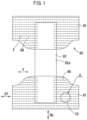
- a wearable article 90 includes an absorbent body 92, and a pair of front and rear around-torso members 91, 91.
- the absorbent body 92 is extended between the pair of around-torso members 91, 91 to form a crotch part 92a.
- the wearable article 90 is worn in the state where the crotch part 92a is folded in half along a virtual line parallel to the around-torso direction X. In this manner, ends in the around-torso direction X of the around-torso members 91, 91 overlap each other.
- Each of the front and rear around-torso members 91 includes the stretchable laminate 10 illustrated clearly in FIG. 2A and FIG. 2B .
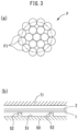
- the stretchable laminate 10 is a sheet-form member in which the elastic member F, and the first and second sheets 1, 2 are laminated on one another.
- the first sheet 1 and the second sheet 2 are formed of a breathable nonwoven fabric.
- the elastic member F is sandwiched between the first sheet 1 and the second sheet 2, and is stretchable in the around-torso direction X.
- the stretchable laminate 10 of the wearable article 90 ( FIG. 1 ) includes a skin surface 11 ( FIG. 2B ) to be in contact with the skin of a wearer and a non-skin surface 12 on the opposite side.
- first surfaces 1f, 2f face each other or are in contact with each other.
- the plurality of elastic members F are disposed between the first surfaces 1f, 2f of the pair of sheets 1, 2, and spaced away from each other, as illustrated by broken lines in FIG. 2A .
- the pair of sheets 1, 2 are jointed to each other at a plurality of joint portions 3 by fusion bonding without an adhesive.
- the pair of sheets 1, 2 are fused to the elastic members F at fixing parts 3f (fusing structure), whereby each of the elastic members F are fixed to the pair of sheets 1, 2 at the fixing parts 3f.
- Each of the joint portions 3 is formed by the pair of sheets 1, 2 fused mutually on the first surfaces 1f, 2f of the pair of sheets 1, 2 in FIG. 2B .
- the joint portions 3 extend in a direction Dp crossing (e.g., orthogonal to) the stretching direction Df of the elastic member F in FIG. 2A , and are spaced from each other in the stretching direction Df.
- each of the joint portions 3 includes a plurality of pairs of first joint portions 31, second joint portions 32, and fixing parts 3f. Between the first joint portion 31 and the second joint portion 32, there is provided a non-joint portion 33 in which the pair of sheets 1, 2 are not jointed to each other.
- the elastic member F may be linear or of rope form.
- the elastic member F may be a multi-strand in which a plurality of rubber threads (fibrous elastic body) F1 are gathered in a bundle.
- the material of the rubber threads F1 may be polyurethane, for example.
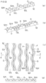
- the stretchable laminate 10 forms a number of pleats P by a shrinkage force of the elastic members F, as illustrated in FIG. 4B .
- the following will describe the stretchable laminate 10 in the state where the elastic members F are shrunk.
- the sheets 1, 2 may be thermoplastic nonwoven fabrics in which a number of thermoplastic fibers are laminated.
- the pleats P of FIG. 4B are formed by the pair of sheets 1, 2 projecting in the direction Dp as in FIG. 4B in the state where the elastic members F of FIG. 2A are shrunk.
- FIG. 2A illustrates the first and second joint portions 31, 32 with diagonal lines.
- the pair of first joint portions 31 are disposed on both sides in the crossing direction Dp of each of the elastic members F.
- the second joint portion 32 is disposed between adjacent elastic members F of the elastic members F and between a pair of first joint portions 31 and another pair of first joint portions 31 adjacent to the pair in the crossing direction Dp.
- one second joint portion 32 is provided between a pair of joint portions 31 and another pair of first joint portions 31.
- the jointing force of the pair of sheets 1, 2 at the second joint portion 32 may be smaller or larger than the jointing force of the pair of sheets 1, 2 at the first joint portion 31.
- the fixing part 3f illustrated by a blank between the pair of first joint portions 31 may have a smaller or larger jointing force than the first joint portion 31.
- the fixing part 3f may have a smaller or larger jointing force than the second joint portion 32. This is because it is sufficient if the elastic member F is fixed to the sheets 1, 2.
- each of the sheets 1, 2 may be fused to the elastic members F, or a part or all of fibers of the nonwoven fabric may be entangled with the elastic members F and fixed thereto.
- the joint portions 31, 32 are provided intermittently in the crossing direction Dp. Therefore, between the joint portions 31, 32 adjacent to each other, there are provided intermittently the non-joint portions 33 where the first and second sheets 1, 2 are not jointed to each other.
- the production device of FIG. 4A includes the anvil roll 50, an introducing device 60, a fusion device 70, and the like.
- the introducing device 60 guides and introduces the elastic member F to the anvil roll 50. Moreover, the first sheet 1 is introduced to the anvil roll 50 at a point further upstream than the elastic member F, and the second sheet 2 is introduced to the anvil roll 50 at a point further downstream than the elastic member F.
- the anvil roll 50 carries the pair of sheets 1, 2 and the elastic member F so that the elastic member F is disposed between the pair of sheets 1, 2.
- the fusion device 70 In cooperation with the anvil roll 50, the fusion device 70 fuses the pair of sheets 1, 2 mutually and fuses the sheets 1, 2 to the elastic member F so that the sheets 1, 2 hold the elastic member F.
- the fusion device 70 is an ultrasonic fusion device performing the fusion bonding by ultrasonic energy.
- the fusion device 70 provides vibrational energy at a plurality of joint portions 3 ( FIG. 2A ) of the two nonwoven fabric sheets 1, 2 in the stretchable laminate 10 of FIG. 2B , so as to fuse the two nonwoven fabric sheets 1, 2 and the elastic member F.
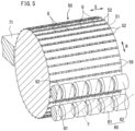
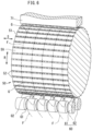
- the anvil roll 50 of FIG. 5 has a number of ridges (projection strips) 52 on an outer peripheral surface 51.
- the ridge 52 extends in the width direction S of the anvil roll 50. That is, the ridge 52 extends along a generatrix parallel to the axis direction of the anvil roll 50.
- the plurality of ridges 52 are spaced from each other in the circumferential direction R of the anvil roll 50, and ridges 52 adjacent to each other among the plurality of ridges 52 define a recessed groove 59 extending in the width direction S.
- Each of the ridges 52 has the plurality of first projections 52H provided intermittently in the width direction S, with each first projection 52H including the carrying groove G.
- the first projections 52H are provided in a matrix form in the circumferential direction R and the width direction S of the roll 50
- the carrying grooves G are provided in a matrix form in the circumferential direction R and the width direction S of the roll 50.
- the fusion device 70 of FIG. 4A includes a horn 71.
- the horn 71 is provided with ultrasonic energy, and faces the ridge 52 of FIG. 4C through the pair of sheets 1, 2 and the elastic member F.
- a width W1 of the horn 71 along the flow direction of the sheets 1, 2 may be larger than a width W2 of the ridge 52.
- the anvil roll 50 has a plurality of carrying grooves G.
- Each of the carrying grooves G is formed by a V-shaped or U-shaped notch formed on each of the plurality of ridges 52, extends in the circumferential direction R of the anvil roll 50 to cross each of the ridges 52, and carries the elastic member F in the state where the elastic member F has entered in.
- the carrying groove G is recessed toward the center in the radial direction of the anvil roll 50.
- the size of the carrying groove G may be set so that a part of the elastic member F is housed in the groove and the remaining part is protruded from the groove.
- the section area of the carrying groove G may be smaller than the section area of the elastic member F of a natural length.
- FIG. 5 to FIG. 8C do not illustrate the sheets 1, 2, the sheets 1, 2 are disposed to sandwich the elastic member F, as illustrated schematically in FIG. 9 .
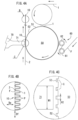
- the introducing device 60 of FIG. 4A includes a first roll (regulation roll) 61 and a second roll (guide roll) 62.
- Each of the first and second rolls 61, 62 of FIG. 5 may have a plurality of first and second guide grooves G1, G2.
- Each of the elastic members F is wound on each of the first guide grooves G1 to guide each of the elastic members F.
- Each of the elastic members F delivered from each of the first guide grooves G1 of the first roll 61 is wound on each of the second guide grooves G2 of FIG. 6 to guide each of the elastic members F to each of the carrying grooves G of the anvil roll 50.
- the first and second rolls 61, 62 may be free rollers, and may be driven to rotate in synchronization with the anvil roll 50. Moreover, the first and second rolls may not be provided.
- each of the ridges 52 has the plurality of carrying grooves G, receiving parts 52L and projections 52H, 52S. That is, each of the ridges 52 includes a plurality of first projections 52H for generating the first joint portions 31, a plurality of second projections 52S for generating the second joint portions 32, and receiving parts 52L for forming the non-joint portions 33.
- FIG. 7 , FIG. 8B , FIG. 8C , and FIG. 9 illustrate the heights of the projections 52L, 52H and the depth of the carrying groove G in an exaggerated manner.
- the first and second projections 52H, 52S, and the receiving parts 52L are provided intermittently along the width direction S of the anvil roll 50, that is, while being spaced in the width direction S.
- the height H1 of the receiving part 52L of FIG. 8B (height from the surface of the recessed groove 59) is smaller than the largest height H2 of the first and second projections 52H, 52S.
- the height H1 of the receiving part 52L is smaller by 70 to 200 ⁇ m, for example, than the height H2 of the projection 52H (height from the surface of the recessed groove 59).
- the carrying groove G is defined by the notch formed in the first projection 52H.
- the lowest surface of the notch of the first projection 52H is set to a height projecting in the radial direction of the roll 50 relative to the bottom surface of the recessed groove 59 illustrated by a broken line.
- the surface of the receiving part 52L is set to a height projecting in the radial direction relative to the lowest surface of the notch, the height retreating (lowering) in the radial direction relative to the top projection surface of the first projection 52H.
- the carrying groove G is defined by (a pair of) regions on both sides in the width direction S of the first projection 52H and the region of the first projection 52H on the lower side of the carrying groove G. That is, the regions on the both sides of the first projection 52H and the region on the lower side of the same first projection 52H define the bottom surface of the carrying groove G.
- a part of the first projection 52H is shaved in a V-shape form, and the carrying groove G is formed to be surrounded by the first projection 52H on the lower side and the both sides in the width direction S.
- a plurality of pairs of first projections 52H are disposed in each of the width direction S and the circumferential direction R of the anvil roll 50. Between the pair of first projections 52H and another pair of first projections 52H that are adjacent to each other in the width direction S, there is disposed the above-described at least one receiving part 52L to receive the pair of sheets 1, 2.
- two receiving parts 52L are provided between the pair of first projections 52H and the another pair of first projections 52H. Between the two receiving parts 52L, there is provided the second projection 52S for generating the second joint portion 32 ( FIG. 2A ) jointing the pair of sheets 1, 2 to each other.
- the first sheet 1 is introduced to the upstream part of the anvil roll 50.
- a plurality of elastic members F are introduced from the introducing device 60 onto the first sheet 1 introduced to the anvil roll 50.
- Each of the elastic members F is introduced, in the state of having entered in the carrying groove G of FIG. 4C , together with the first sheet ( FIG. 4A ).
- the first sheet 1 and the elastic member F are carried while the first sheet 1 is received at the receiving parts 52L between a pair of first projections 52H and another pair of first projections 52H as illustrated by two-dot chain lines in FIG. 9 , and each pair of first projections produces (generates) the pair of first joint portions 31, 31 later.
- the second sheet 2 of FIG. 4A is introduced to the region of the anvil roll 50 facing the horn 71 of FIG. 4C . That is, on the anvil roll 50, the second sheet 2 is introduced onto the first sheet 1 so as to sandwich the elastic members F between the first sheet 1 and the second sheet 2.
- the horn 71 is ultrasonically vibrated in the direction toward the anvil roll 50.
- the sheets 1, 2 are fused mutually at the first joint portions 31 and the second joint portions 32 of FIG. 2A , and the sheets 1, 2 are fused to the elastic members F at the fixing parts 3f.
- the stretchable laminate 10 is generated.
- first sheet 1 and the second sheet 2 are not fused at the receiving parts 52L of FIG. 7 and FIG. 8B , and the first sheet 1 and the second sheet 2 are fused on each of the projections 52H, 52S of the anvil roll 50, thus forming the joint portions 3.
- the pair of sheets 1, 2 pass between the first projection 52H or the second projection 52S of the ridge 52 and the horn 71 in the direction orthogonal to a paper surface of the figure.
- each of the projections 52H, 52S of FIG. 9 the horn 71 is in contact with the second sheet 2 with large pressure. Therefore, each of the projections 52H, 52S intermittently generates the first and second joint portions 31, 32 of FIG. 2A in the stretching direction Df of the elastic member F, and the pair of sheets 1, 2 are ultrasonically fused securely there.
- FIG. 10 illustrates a modification
- the shape of the receiving part 52L may be circular or the like, other than rectangular. Moreover, the receiving part 52L may project further in the circumferential direction than each of the first projections 52H or may be shorter in the circumferential direction.
- the receiving part 52L may be continuous to the first projection 52H or may be formed intermittently.
- the surface 52f of the ridge 52 between the first projection 52H and the receiving part 52L and the first projection 52H may meander (be continuous in a zigzag form) relative to the elastic member F of the stretchable laminate 10.
- the width of the receiving part 52L may not be constant.
- the carrying grooves G are provided intermittently in the first projections 52H in the extending direction of the elastic member F. That is, only at the regions where the first projection 52H crosses the elastic member F, the carrying grooves G are provided along the extending direction of the elastic member F.
- FIG. 10(d) illustrates the elastic members F by two-dot chain lines.
- the receiving part 52L may have the same height as the outer peripheral surface of the anvil roll 50. Moreover, although the effect of preventing displacement of the elastic member is not expected in such a case, the receiving parts 52L may be formed at intermittent portions in the circumferential direction of the projections for jointing.
- the roll for introduction is not necessarily provided.
- the fusion bonding may not be ultrasonic but of heat sealing.
- the present invention may be applied to the production of the stretchable laminate that is preferably used for diaper-type and underpants-type disposable wearable articles.
Landscapes
- Engineering & Computer Science (AREA)
- Health & Medical Sciences (AREA)
- Mechanical Engineering (AREA)
- Animal Behavior & Ethology (AREA)
- Public Health (AREA)
- Epidemiology (AREA)
- Biomedical Technology (AREA)
- Heart & Thoracic Surgery (AREA)
- Vascular Medicine (AREA)
- Life Sciences & Earth Sciences (AREA)
- Veterinary Medicine (AREA)
- General Health & Medical Sciences (AREA)
- Manufacturing & Machinery (AREA)
- Textile Engineering (AREA)
- Physics & Mathematics (AREA)
- Fluid Mechanics (AREA)
- Absorbent Articles And Supports Therefor (AREA)
- Lining Or Joining Of Plastics Or The Like (AREA)
- Supply And Installment Of Electrical Components (AREA)
- Laminated Bodies (AREA)
Claims (5)
- Dispositif de production d'un stratifié extensible pour un article portable, comprenant :un rouleau d'enclume (50) qui porte une paire de première et deuxième feuilles (1, 2) et des éléments élastiques (F) de sorte que les éléments élastiques (F) sont pris en sandwich entre la paire de première et deuxième feuilles (1, 2), et un dispositif de fusion (70) qui, en coopération avec le rouleau d'enclume (50), fusionne la paire de première et deuxième feuilles (1, 2) mutuellement et fait en sorte que la paire de première et deuxième feuilles (1, 2) maintienne les éléments élastiques (F), dans lequelune surface périphérique extérieure (51) du rouleau d'enclume (50) comprend une pluralité de premières saillies (52H) pour produire des premières parties de joint (31) avec la paire de première et deuxième feuilles (1, 2) jointes l'une à l'autre, les premières saillies étant fournies le long d'une direction de largeur S du rouleau d'enclume (50) et espacées l'une de l'autre dans la direction de largeur S,chacune des premières saillies (52H) définit et comprend une rainure de transport (G) s'étendant dans une direction circonférentielle R du rouleau d'enclume (50) et transportant chacun des éléments élastiques (F) lorsque chacun des éléments élastiques (F) est entré dans la rainure (G), etau moins une partie de réception (52L) pour recevoir la paire de première et deuxième feuilles (1, 2) est disposée entre une première saillie (52H) et une autre première saillie (52H) adjacentes l'une à l'autre dans la direction de la largeur S, parmi la pluralité de premières saillies (52H) comprenant chacune la rainure de transport (G) ;dans laquellel'au moins une partie de réception comprend au moins deux parties de réception (52L) placées entre la première saillie (52H) et l'autre première saillie (52H), etune deuxième saillie (52S) destinée à produire une deuxième partie de joint (32) avec la paire de première et deuxième feuilles (1, 2) jointes l'une à l'autre est prévue entre les au moins deux parties de réception (52L).
- Dispositif de production d'un stratifié étirable selon la revendication 1, dans lequel une hauteur de la au moins une partie réceptrice (52L) est inférieure à une hauteur des premières saillies (52H) de 51 à 300 µm.
- Le dispositif de production d'un laminé étirable selon la revendication 1, dans lequella surface périphérique extérieure (51) du rouleau d'enclume (50) comprend une pluralité de stries (52) s'étendant le long de la direction de la largeur S du rouleau d'enclume (50) et espacées les unes des autres dans la direction circonférentielle R du rouleau d'enclume (50),les crêtes (52) adjacentes les unes aux autres parmi la pluralité de crêtes (52) définissent une rainure en retrait (59) s'étendant dans la direction de la largeur S,chacune des nervures (52) comprend la pluralité de premières saillies (52H) comportant chacune la rainure de transport (G), les premières saillies (52H) étant fournies de manière intermittente dans la direction de la largeur S, etles crêtes (52) et les rainures en retrait (59) sont formées de telle sorte queles premières saillies (52H) sont fournies sous forme de matrice dans la direction circonférentielle R et la direction de la largeur S du rouleau d'enclume (50), etles rainures de transport (G) sont fournies sous forme de matrice dans la direction circonférentielle R et dans la direction de la largeur du rouleau d'enclume (50).
- Méthode de production d'un laminé extensible (10) pour un article portable,le laminé étirable (10) comprend plusieurs éléments élastiques (F) espacés les uns des autres et pris en sandwich par une première feuille (1) et une deuxième feuille (2), la première et la deuxième feuilles (1, 2) étant jointes l'une à l'autre à chacune des premières parties de joint (31), les premières parties de joint (31) étant disposées en colonnes dans une direction d'étirement Df des éléments élastiques (F) et disposées en rangées dans une direction Dp croisant la direction d'étirement Df,le procédé comprenantune étape d'introduction de la première feuille (1) sur un rouleau enclume (50) ;une étape d'introduction des éléments élastiques (F) sur la première feuille (1) sur le rouleau d'enclume (50) et d'introduction des éléments élastiques (F) de sorte que chacun des éléments élastiques (F) entre dans chacune des rainures porteuses (G) du rouleau d'enclume (50) ;une étape consistant à transporter la première feuille (1) et les éléments élastiques (F) tout en recevant la première feuille (1) dans une partie de réception (52L) entre une première saillie (52H) et une autre première saillie (52H), chacune comprenant les rainures de transport respectives (G), de manière à supprimer le retrait de la première feuille (1) dans une direction radiale du rouleau d'enclume (50) ;une étape d'introduction, sur le rouleau enclume (50), de la deuxième feuille (2) sur la première feuille (1) de manière à prendre en sandwich les éléments élastiques (F) entre la première feuille (1) et la deuxième feuille (2) ; etune étape de formation des premières portions de joint (31) par fusion de la première feuille (1) et de la seconde feuille (2) sur l'une et l'autre des premières saillies (52H) du rouleau d'enclume (50) sans fusion de la première feuille (1) et de la seconde feuille (2) au niveau de la partie réceptrice (52L).
- Procédé de fabrication d'un laminé étirable selon la revendication 4, dans lequel
lors de l'étape de transport de la première feuille (1) et des éléments élastiques (F), la partie de réception (52L) reçoit la première feuille (1), la hauteur de la partie de réception (52L) étant inférieure de 51 à 300 µm à la hauteur de la première saillie (52H).
Applications Claiming Priority (2)
| Application Number | Priority Date | Filing Date | Title |
|---|---|---|---|
| JP2017127603 | 2017-06-29 | ||
| PCT/JP2018/022518 WO2019003908A1 (fr) | 2017-06-29 | 2018-06-13 | Dispositif et procédé de production de stratifié étirable pour article vestimentaire |
Publications (4)
| Publication Number | Publication Date |
|---|---|
| EP3646830A1 EP3646830A1 (fr) | 2020-05-06 |
| EP3646830A4 EP3646830A4 (fr) | 2021-03-24 |
| EP3646830B1 true EP3646830B1 (fr) | 2025-05-21 |
| EP3646830C0 EP3646830C0 (fr) | 2025-05-21 |
Family
ID=64741528
Family Applications (1)
| Application Number | Title | Priority Date | Filing Date |
|---|---|---|---|
| EP18823118.7A Active EP3646830B1 (fr) | 2017-06-29 | 2018-06-13 | Dispositif et procédé de production de stratifié étirable pour article vestimentaire |
Country Status (7)
| Country | Link |
|---|---|
| US (1) | US11191676B2 (fr) |
| EP (1) | EP3646830B1 (fr) |
| JP (1) | JP7077318B2 (fr) |
| KR (1) | KR102475149B1 (fr) |
| CN (1) | CN110650715B (fr) |
| MX (1) | MX2019013401A (fr) |
| WO (1) | WO2019003908A1 (fr) |
Families Citing this family (12)
| Publication number | Priority date | Publication date | Assignee | Title |
|---|---|---|---|---|
| US10792194B2 (en) | 2014-08-26 | 2020-10-06 | Curt G. Joa, Inc. | Apparatus and methods for securing elastic to a carrier web |
| EP3558189B1 (fr) * | 2016-12-20 | 2021-06-23 | The Procter & Gamble Company | Procédés et appareils pour fabriquer des stratifiés élastomères avec des brins élastiques dotés d'une finition de filage |
| CA3088550A1 (fr) | 2018-01-29 | 2019-08-01 | Curt G. Joa, Inc. | Appareil et procede de fabrication d'une structure composite elastique pour un produit hygienique absorbant |
| US11925538B2 (en) * | 2019-01-07 | 2024-03-12 | Curt G. Joa, Inc. | Apparatus and method of manufacturing an elastic composite structure for an absorbent sanitary product |
| WO2020230479A1 (fr) * | 2019-05-13 | 2020-11-19 | 株式会社瑞光 | Appareil de fabrication d'élément étirable composite |
| WO2020246398A1 (fr) * | 2019-06-04 | 2020-12-10 | 花王株式会社 | Feuille étirable et article absorbant pourvu de ladite feuille |
| JP7545230B2 (ja) * | 2019-06-04 | 2024-09-04 | 花王株式会社 | 伸縮性シート、及び該伸縮性シートを備えた吸収性物品 |
| US12433797B2 (en) | 2019-09-04 | 2025-10-07 | Curt G. Joa, Inc. | Elastic entrapment with waist cap bonding |
| US11173072B2 (en) * | 2019-09-05 | 2021-11-16 | Curt G. Joa, Inc. | Curved elastic with entrapment |
| EP4106699B1 (fr) | 2020-02-17 | 2025-10-15 | Curt G. Joa, Inc. | Structure composite élastique pour produit sanitaire absorbant et appareil et procédé de fabrication de ladite structure composite élastique |
| JP7505965B2 (ja) * | 2020-11-04 | 2024-06-25 | 花王株式会社 | 伸縮性複合シートの製造方法及び製造装置 |
| WO2025080902A1 (fr) | 2023-10-11 | 2025-04-17 | Dukane Ias, Llc | Appareil et procédé pour piéger un matériau élastomère avec des régions élastomères à ajustement de forme |
Family Cites Families (12)
| Publication number | Priority date | Publication date | Assignee | Title |
|---|---|---|---|---|
| US4915767A (en) * | 1988-11-17 | 1990-04-10 | Kimberly-Clark Corporation | Apparatus for applying an elastic in a curved pattern to a moving web |
| JP4322140B2 (ja) | 2004-01-30 | 2009-08-26 | 花王株式会社 | 複合伸縮部材及びその製造方法 |
| EP1666178B1 (fr) * | 2003-09-08 | 2017-05-24 | Kao Corporation | Élément composite extensible et procédé de fabrication associé |
| JP5367961B2 (ja) | 2006-07-07 | 2013-12-11 | ユニ・チャーム株式会社 | 使い捨ておむつ、シート部材およびプリーツシートの製造方法 |
| JP5256114B2 (ja) | 2009-05-11 | 2013-08-07 | 花王株式会社 | 複合伸縮部材の製造方法およびその製造装置 |
| JP6012378B2 (ja) | 2012-09-28 | 2016-10-25 | ユニ・チャーム株式会社 | 使い捨てオムツ |
| JP5857087B2 (ja) | 2014-04-28 | 2016-02-10 | ユニ・チャーム株式会社 | 吸収性物品に係る複数のシートの固定装置、及び固定方法 |
| JP6281465B2 (ja) | 2014-10-17 | 2018-02-21 | 王子ホールディングス株式会社 | 伸縮シートの製造方法及び製造装置 |
| JP5984156B2 (ja) * | 2014-11-19 | 2016-09-06 | 大王製紙株式会社 | 吸収性物品の製造方法及び吸収性物品 |
| US10786398B2 (en) | 2015-06-22 | 2020-09-29 | Zuiko Corporation | Production device and production method for composite stretchable member |
| JP6625126B2 (ja) * | 2015-06-22 | 2019-12-25 | 株式会社瑞光 | 複合伸縮部材、着用物品および着用物品の製造方法 |
| KR102499641B1 (ko) | 2016-10-14 | 2023-02-15 | 가부시키가이샤 즈이코 | 신축 시트, 그것을 사용한 착용 물품 및 신축 시트의 제조 장치 |
-
2018
- 2018-06-13 KR KR1020197032883A patent/KR102475149B1/ko active Active
- 2018-06-13 CN CN201880033468.7A patent/CN110650715B/zh active Active
- 2018-06-13 MX MX2019013401A patent/MX2019013401A/es unknown
- 2018-06-13 JP JP2019526782A patent/JP7077318B2/ja active Active
- 2018-06-13 WO PCT/JP2018/022518 patent/WO2019003908A1/fr not_active Ceased
- 2018-06-13 US US16/614,736 patent/US11191676B2/en active Active
- 2018-06-13 EP EP18823118.7A patent/EP3646830B1/fr active Active
Also Published As
| Publication number | Publication date |
|---|---|
| KR102475149B1 (ko) | 2022-12-07 |
| JPWO2019003908A1 (ja) | 2020-04-30 |
| KR20200023605A (ko) | 2020-03-05 |
| CN110650715B (zh) | 2021-09-14 |
| BR112019025368A2 (pt) | 2020-08-18 |
| WO2019003908A1 (fr) | 2019-01-03 |
| US11191676B2 (en) | 2021-12-07 |
| JP7077318B2 (ja) | 2022-05-30 |
| EP3646830A4 (fr) | 2021-03-24 |
| US20200179180A1 (en) | 2020-06-11 |
| MX2019013401A (es) | 2020-02-07 |
| EP3646830A1 (fr) | 2020-05-06 |
| EP3646830C0 (fr) | 2025-05-21 |
| CN110650715A (zh) | 2020-01-03 |
Similar Documents
| Publication | Publication Date | Title |
|---|---|---|
| EP3646830B1 (fr) | Dispositif et procédé de production de stratifié étirable pour article vestimentaire | |
| EP3527182B1 (fr) | Feuille étirable, article à porter l'utilisant, et dispositif de production de feuille étirable | |
| EP3527181B1 (fr) | Feuille étirable, article à porter l'utilisant, et dispositif de production de feuille étirable | |
| EP3296100B1 (fr) | Élément composite étirable, article vestimentaire et procédé de fabrication de l'article | |
| JP5028654B2 (ja) | 積層伸縮シートおよびその製造方法 | |
| EP1938777B1 (fr) | Procédé pour la fabrication d'un article usagé jetable | |
| JP4934835B2 (ja) | 積層伸縮シートの製造方法 | |
| EP3788997B1 (fr) | Piégeage élastique avec une liaison de capuchon à la taille | |
| CN106456383B (zh) | 吸收性物品的多个片材的固定装置以及固定方法 | |
| EP3977970B1 (fr) | Procede de fabrication d'article a porter | |
| KR102860917B1 (ko) | 신축 적층 시트, 일회용 착용 물품, 신축 적층 시트의 제조 방법 및 제조 장치 | |
| WO2024215737A1 (fr) | Produits de culotte et système et leur procédé de formation | |
| BR112019025368B1 (pt) | Dispositivo e método para produção de laminado dilatável para artigo próprio para ser usado |
Legal Events
| Date | Code | Title | Description |
|---|---|---|---|
| STAA | Information on the status of an ep patent application or granted ep patent |
Free format text: STATUS: THE INTERNATIONAL PUBLICATION HAS BEEN MADE |
|
| PUAI | Public reference made under article 153(3) epc to a published international application that has entered the european phase |
Free format text: ORIGINAL CODE: 0009012 |
|
| STAA | Information on the status of an ep patent application or granted ep patent |
Free format text: STATUS: REQUEST FOR EXAMINATION WAS MADE |
|
| 17P | Request for examination filed |
Effective date: 20191106 |
|
| AK | Designated contracting states |
Kind code of ref document: A1 Designated state(s): AL AT BE BG CH CY CZ DE DK EE ES FI FR GB GR HR HU IE IS IT LI LT LU LV MC MK MT NL NO PL PT RO RS SE SI SK SM TR |
|
| AX | Request for extension of the european patent |
Extension state: BA ME |
|
| DAV | Request for validation of the european patent (deleted) | ||
| DAX | Request for extension of the european patent (deleted) | ||
| REG | Reference to a national code |
Ref country code: DE Ref legal event code: R079 Ref document number: 602018082145 Country of ref document: DE Free format text: PREVIOUS MAIN CLASS: A61F0013150000 Ipc: B29C0065080000 |
|
| RIC1 | Information provided on ipc code assigned before grant |
Ipc: B29C 65/02 20060101AFI20210205BHEP |
|
| A4 | Supplementary search report drawn up and despatched |
Effective date: 20210224 |
|
| RIC1 | Information provided on ipc code assigned before grant |
Ipc: B29L 31/48 20060101ALN20210218BHEP Ipc: B29C 65/08 20060101AFI20210218BHEP Ipc: A61F 13/49 20060101ALN20210218BHEP |
|
| STAA | Information on the status of an ep patent application or granted ep patent |
Free format text: STATUS: EXAMINATION IS IN PROGRESS |
|
| 17Q | First examination report despatched |
Effective date: 20230620 |
|
| GRAP | Despatch of communication of intention to grant a patent |
Free format text: ORIGINAL CODE: EPIDOSNIGR1 |
|
| STAA | Information on the status of an ep patent application or granted ep patent |
Free format text: STATUS: GRANT OF PATENT IS INTENDED |
|
| INTG | Intention to grant announced |
Effective date: 20241217 |
|
| RIC1 | Information provided on ipc code assigned before grant |
Ipc: B29L 31/48 20060101ALN20241209BHEP Ipc: A61F 13/49 20060101ALN20241209BHEP Ipc: B29C 65/08 20060101AFI20241209BHEP |
|
| GRAS | Grant fee paid |
Free format text: ORIGINAL CODE: EPIDOSNIGR3 |
|
| GRAA | (expected) grant |
Free format text: ORIGINAL CODE: 0009210 |
|
| STAA | Information on the status of an ep patent application or granted ep patent |
Free format text: STATUS: THE PATENT HAS BEEN GRANTED |
|
| AK | Designated contracting states |
Kind code of ref document: B1 Designated state(s): AL AT BE BG CH CY CZ DE DK EE ES FI FR GB GR HR HU IE IS IT LI LT LU LV MC MK MT NL NO PL PT RO RS SE SI SK SM TR |
|
| REG | Reference to a national code |
Ref country code: GB Ref legal event code: FG4D |
|
| REG | Reference to a national code |
Ref country code: CH Ref legal event code: EP |
|
| REG | Reference to a national code |
Ref country code: DE Ref legal event code: R096 Ref document number: 602018082145 Country of ref document: DE |
|
| REG | Reference to a national code |
Ref country code: IE Ref legal event code: FG4D |
|
| U01 | Request for unitary effect filed |
Effective date: 20250612 |
|
| U07 | Unitary effect registered |
Designated state(s): AT BE BG DE DK EE FI FR IT LT LU LV MT NL PT RO SE SI Effective date: 20250623 |
|
| U20 | Renewal fee for the european patent with unitary effect paid |
Year of fee payment: 8 Effective date: 20250728 |
|
| PG25 | Lapsed in a contracting state [announced via postgrant information from national office to epo] |
Ref country code: ES Free format text: LAPSE BECAUSE OF FAILURE TO SUBMIT A TRANSLATION OF THE DESCRIPTION OR TO PAY THE FEE WITHIN THE PRESCRIBED TIME-LIMIT Effective date: 20250521 |
|
| PG25 | Lapsed in a contracting state [announced via postgrant information from national office to epo] |
Ref country code: NO Free format text: LAPSE BECAUSE OF FAILURE TO SUBMIT A TRANSLATION OF THE DESCRIPTION OR TO PAY THE FEE WITHIN THE PRESCRIBED TIME-LIMIT Effective date: 20250821 Ref country code: GR Free format text: LAPSE BECAUSE OF FAILURE TO SUBMIT A TRANSLATION OF THE DESCRIPTION OR TO PAY THE FEE WITHIN THE PRESCRIBED TIME-LIMIT Effective date: 20250822 |
|
| PG25 | Lapsed in a contracting state [announced via postgrant information from national office to epo] |
Ref country code: PL Free format text: LAPSE BECAUSE OF FAILURE TO SUBMIT A TRANSLATION OF THE DESCRIPTION OR TO PAY THE FEE WITHIN THE PRESCRIBED TIME-LIMIT Effective date: 20250521 |
|
| PG25 | Lapsed in a contracting state [announced via postgrant information from national office to epo] |
Ref country code: HR Free format text: LAPSE BECAUSE OF FAILURE TO SUBMIT A TRANSLATION OF THE DESCRIPTION OR TO PAY THE FEE WITHIN THE PRESCRIBED TIME-LIMIT Effective date: 20250521 |
|
| PG25 | Lapsed in a contracting state [announced via postgrant information from national office to epo] |
Ref country code: RS Free format text: LAPSE BECAUSE OF FAILURE TO SUBMIT A TRANSLATION OF THE DESCRIPTION OR TO PAY THE FEE WITHIN THE PRESCRIBED TIME-LIMIT Effective date: 20250821 |
|
| PG25 | Lapsed in a contracting state [announced via postgrant information from national office to epo] |
Ref country code: IS Free format text: LAPSE BECAUSE OF FAILURE TO SUBMIT A TRANSLATION OF THE DESCRIPTION OR TO PAY THE FEE WITHIN THE PRESCRIBED TIME-LIMIT Effective date: 20250921 |