EP3645989B1 - System und verfahren zur berechnung der um den strahlungsfehler korrigierten temperatur einer externen umgebung sowie sensorvorrichtung zur verwendung in einem solchen system - Google Patents
System und verfahren zur berechnung der um den strahlungsfehler korrigierten temperatur einer externen umgebung sowie sensorvorrichtung zur verwendung in einem solchen system Download PDFInfo
- Publication number
- EP3645989B1 EP3645989B1 EP18747012.5A EP18747012A EP3645989B1 EP 3645989 B1 EP3645989 B1 EP 3645989B1 EP 18747012 A EP18747012 A EP 18747012A EP 3645989 B1 EP3645989 B1 EP 3645989B1
- Authority
- EP
- European Patent Office
- Prior art keywords
- temperature
- speed
- ratio
- seat
- sensor
- Prior art date
- Legal status (The legal status is an assumption and is not a legal conclusion. Google has not performed a legal analysis and makes no representation as to the accuracy of the status listed.)
- Active
Links
Images


Classifications
-
- G—PHYSICS
- G01—MEASURING; TESTING
- G01K—MEASURING TEMPERATURE; MEASURING QUANTITY OF HEAT; THERMALLY-SENSITIVE ELEMENTS NOT OTHERWISE PROVIDED FOR
- G01K1/00—Details of thermometers not specially adapted for particular types of thermometer
- G01K1/20—Compensating for effects of temperature changes other than those to be measured, e.g. changes in ambient temperature
-
- G—PHYSICS
- G01—MEASURING; TESTING
- G01K—MEASURING TEMPERATURE; MEASURING QUANTITY OF HEAT; THERMALLY-SENSITIVE ELEMENTS NOT OTHERWISE PROVIDED FOR
- G01K13/00—Thermometers specially adapted for specific purposes
- G01K13/02—Thermometers specially adapted for specific purposes for measuring temperature of moving fluids or granular materials capable of flow
-
- B—PERFORMING OPERATIONS; TRANSPORTING
- B60—VEHICLES IN GENERAL
- B60H—ARRANGEMENTS OF HEATING, COOLING, VENTILATING OR OTHER AIR-TREATING DEVICES SPECIALLY ADAPTED FOR PASSENGER OR GOODS SPACES OF VEHICLES
- B60H1/00—Heating, cooling or ventilating [HVAC] devices
- B60H1/00642—Control systems or circuits; Control members or indication devices for heating, cooling or ventilating devices
- B60H1/00735—Control systems or circuits characterised by their input, i.e. by the detection, measurement or calculation of particular conditions, e.g. signal treatment, dynamic models
- B60H1/00807—Control systems or circuits characterised by their input, i.e. by the detection, measurement or calculation of particular conditions, e.g. signal treatment, dynamic models the input being a specific way of measuring or calculating an air or coolant temperature
-
- G—PHYSICS
- G01—MEASURING; TESTING
- G01K—MEASURING TEMPERATURE; MEASURING QUANTITY OF HEAT; THERMALLY-SENSITIVE ELEMENTS NOT OTHERWISE PROVIDED FOR
- G01K13/00—Thermometers specially adapted for specific purposes
- G01K13/02—Thermometers specially adapted for specific purposes for measuring temperature of moving fluids or granular materials capable of flow
- G01K13/024—Thermometers specially adapted for specific purposes for measuring temperature of moving fluids or granular materials capable of flow of moving gases
-
- G—PHYSICS
- G01—MEASURING; TESTING
- G01K—MEASURING TEMPERATURE; MEASURING QUANTITY OF HEAT; THERMALLY-SENSITIVE ELEMENTS NOT OTHERWISE PROVIDED FOR
- G01K2201/00—Application of thermometers in air-conditioning systems
- G01K2201/02—Application of thermometers in air-conditioning systems in vehicles
-
- G—PHYSICS
- G01—MEASURING; TESTING
- G01K—MEASURING TEMPERATURE; MEASURING QUANTITY OF HEAT; THERMALLY-SENSITIVE ELEMENTS NOT OTHERWISE PROVIDED FOR
- G01K7/00—Measuring temperature based on the use of electric or magnetic elements directly sensitive to heat ; Power supply therefor, e.g. using thermoelectric elements
- G01K7/02—Measuring temperature based on the use of electric or magnetic elements directly sensitive to heat ; Power supply therefor, e.g. using thermoelectric elements using thermoelectric elements, e.g. thermocouples
-
- G—PHYSICS
- G01—MEASURING; TESTING
- G01K—MEASURING TEMPERATURE; MEASURING QUANTITY OF HEAT; THERMALLY-SENSITIVE ELEMENTS NOT OTHERWISE PROVIDED FOR
- G01K7/00—Measuring temperature based on the use of electric or magnetic elements directly sensitive to heat ; Power supply therefor, e.g. using thermoelectric elements
- G01K7/16—Measuring temperature based on the use of electric or magnetic elements directly sensitive to heat ; Power supply therefor, e.g. using thermoelectric elements using resistive elements
-
- G—PHYSICS
- G01—MEASURING; TESTING
- G01K—MEASURING TEMPERATURE; MEASURING QUANTITY OF HEAT; THERMALLY-SENSITIVE ELEMENTS NOT OTHERWISE PROVIDED FOR
- G01K7/00—Measuring temperature based on the use of electric or magnetic elements directly sensitive to heat ; Power supply therefor, e.g. using thermoelectric elements
- G01K7/42—Circuits effecting compensation of thermal inertia; Circuits for predicting the stationary value of a temperature
Definitions
- the present invention generally applies to the field of meteorology, and in particular it regards a system and a method for calculating the air temperature of an external environment corrected from the radiative error.
- the invention also regards a sensor device that can be used in such system.
- Air temperature detection devices designated to be positioned in an outdoor environment generally comprising at least one temperature measuring sensor are known.
- the prior art devices provide for a box-shaped body for screening the sensor at least partly.
- the box-shaped body In order for the screening to have significant effect on the reduction of the radiative error, it is necessary for the box-shaped body to have a particular configuration, enable the through-flow of air and have considerable dimensions.
- An object of the present invention is to at least partly overcome the drawbacks illustrated above, by providing a sensor device, a method and/or a system for calculating the air temperature corrected from the radiative error that is highly functional and inexpensive.
- Another object of the invention is to provide a sensor device, a system and/or a method for calculating the air temperature with an extremely short response time.
- a further object of the invention is to provide a sensor device to calculate the air temperature of small dimensions.
- Another object of the invention is to provide a system and/or a method for calculating the air temperature in a precise and inexpensive manner.
- a system 1 for calculating the air temperature T of an external environment E in particular an external environment E subjected to thermal radiation, for example solar radiation.
- the system 1 may comprise at least one sensor device 10 positioned in the external environment E and at least one data processing logic unit 50 operatively connected with the sensor device 10 for processing the data detected by the sensor device 10 and calculating the air temperature T .
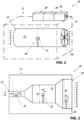
- the device 10 may be positioned fixed in an external environment, for example a garden, a terrace or the like or it may be positioned on a mobile device, a vehicle for example.
- the data processing logic unit 50 may be arranged in proximity of the sensor device 10 or it may be spaced from the latter and remote-connected for example by means of wireless connection.
- the sensor device 10 may detect one of more temperature values Ts1 , Ts2 , Ts3 , preferably at least two temperature values Ts1 , Ts2 , while the data processing logic unit 50 may calculate the air temperature T starting from such values Ts1 , Ts2 and possibly Ts3 and from other values, as better specified hereinafter.
- the sensor device 10 may comprise a support structure 11 with a seat 12 designated to be traversed by the air of the external environment E .
- the seat 12 may have an air inlet 13 and an air outlet 14 .
- the support structure 11 may be substantially cylindrical or parallelepiped-shaped, while the seat 12 may have a substantially longitudinal extension.
- the geometry of the seat 12 be such to minimise the air turbulence of the external environment E which traverses it, i.e. in other words that the motion of the latter be of the laminar type as much as possible.
- the sensor device 10 may suitably comprise sensor means 20 arranged inside the seat 12 to detect the temperature values Ts1 , Ts2 and possibly Ts3 of the air that traverses the seat 12 .
- each temperature value Ts1 , Ts2 and possibly Ts3 of the air may be detected at a corresponding air speed V1 , V2 and possibly V3 .
- Such speeds V1 , V2 and possibly V3 are different from each other.
- the sensor means 20 may comprise at least one temperature sensor 21 in at least one predetermined position.
- the sensor means 20 may comprise only one temperature sensor 21 .
- the sensor device 10 may comprise means 30 for varying the air speed in the seat 12 , in particular at the predetermined position of the sensor 21 .
- the means 30 may include a ventilator, a fan or the like which may be arranged at the inlet 13 and/or at the outlet 14 of the seat 12 .
- Adjustment means 40 acting on the air speed variation means 30 so as to enable the adjustment of the air speed may be suitably provided for.
- the sensor 21 may detect the temperature value Ts1 at speed V1 and the temperature value Ts2 at speed V2 . Furthermore, the sensor 21 may also detect the temperature value Ts3 at speed V3 .
- the sensor means 20 may comprise a plurality of sensors 21 , 22 , 23 each arranged in a respective predetermined position in the seat 12 to detect a respective temperature value Ts1 , Ts2 , Ts3 of the air having a respective speed V1 , V2 , V3 .
- the support structure 11 may be configured so that the sensors 21 , 22 , 23 are all substantially exposed to the same thermal radiation.
- the radiant power Prad may be substantially equal for all sensors 21 , 22 , 23 .
- the support structure 11 may be entirely made of the same material, while the seat 12 may have a substantially continuous lateral surface.
- the radiant power Prad that impacts the sensors may be different but predetermined in any case, as better outlined hereinafter.
- the sensors 21 , 22 , 23 may be of any type, for example thermocouples or resistance thermometers (RTD: Resistance Temperature Detector) and they may be particularly small in size.
- thermocouples or resistance thermometers (RTD: Resistance Temperature Detector) and they may be particularly small in size.
- the sensors 21 , 22 , 23 may preferably be all identical to each other.
- the sensors 21 , 22 , 23 may be mounted on a printed circuit board (PCB) or on any other similar device.
- PCB printed circuit board
- the seat 12 may suitably be configured so that the air speed V1 , V2 , V3 at the respective sensors 21, 22, 23 are different from each other when detecting the temperature Ts1 , Ts2 , Ts3 .
- the seat 12 may be substantially cylindrical-shaped and it may have section variations at the position of the sensors 21 , 22 , 23 .
- the seat 12 may have sections S1 , S2 , S3 different from each other so that the air has a respective speed V1 , V2 , V3 at the respective sensor 21 , 22 , 23 .
- the seat 12 may possibly have a geometric configuration such to enable the known "Venturi effect" and the sensors 21 , 22 may be positioned so that the air impacts them with speeds V1 , V2 different from each other, possibly with a predetermined and constant ratio between the speeds V1 , V2 .
- the movement of air in the seat 12 may be promoted by the aforementioned means 30 , or the sensor device 10 may be impacted by the wind or it may be mounted on a mobile device, a vehicle for example.
- the geometry of the seat 12 will enable to predetermine the values of the ratios V1/V2 , V1/V3 , V2/V3 from among the speeds that impact the sensors 21 , 22 and 23 .
- the geometry of the seat 12 may enable to predetermine the ratio values H1/H2 , H1/H3 , H2/H3 between the heat transfer coefficients of the sensors 21 , 22 and 23 starting from the predetermination of speed ratios, as better outlined hereinafter.
- the configuration of the seat 12 may enable to predetermine the ratio values PRad2/PRad1 , PRad3/PRad1 , PRad3/PRad2 between the radiant powers that impact the sensors 21 , 22 and 23 .
- the seat 12 may have a differentiated thickness or it may have the configuration of FIG. 5 , as outlined hereinafter.
- the data processing logic unit 50 may calculate the temperature T of the air of the external environment E which traverses the seat 12 of the sensor device 10 corrected from the radiative error starting from such detected temperature values Ts1 and Ts2 , from the ratio PRad2/PRad1 and from the ratio V1/V2 of from the ratio H1/H2.
- the system 1 may comprise a storage unit 60 operatively connected with the data processing logic unit 50.
- the storage unit 60 may be arranged in proximity of the support structure 11 or it may be remote and connected with the data processing logic unit 50 by means of wireless connection.
- the speeds V1 , V2 may be possibly stored in the storage unit 60 so as to rapidly calculate such ratio V1/V2.
- the ratio V1/V2 and not the single speeds V1 , V2 may be preferably stored in the storage unit 60.
- the temperature values Ts1 , Ts2 and possibly Ts3 may be detected by the same sensor 21 or by different sensors 21 , 22 .
- the temperature seen from the sensor T ir is the temperature of the external bodies which irradiate on the sensor.
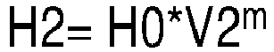
- parameter H0 depends on the geometric and thermodynamic characteristics of the sensor which does not have to be known due to the fact that the formulae use H1/H2
- parameter m depends on the geometric and thermodynamic characteristics of the sensor and it may be predetermined by means of a simple calibration procedure, as explained hereinafter.
- the calibration procedure for determining parameter m may consist in subjecting the sensor to be characterised to constant thermal radiation in an environment with controlled temperature (known and constant) by carrying out two temperature detections Ts1 , Ts2 at two different speeds whose ratio is known.
- the first two formulae (1) and (2) show the equations of the thermal balance for the sensors 21 and 22 , while the formula (3) shows the relationship between the ratio of the transfer coefficients H1/H2 and the ratio V1/V2.
- the parameter m may be stored in the storage unit 60.
- the ratio H1/H2 may be possibly stored in the storage unit 60 so as to calculate the air temperature T by means of the correlations outlined above.
- the data processing logic unit 50 may calculate the temperatures T that are known V1 , V2 , m , Ts1 and Ts2.
- the respective output radiation IRout1 , IRout2 may be substantially negligible as compared to the other terms of the correlations.
- the correlations (3), (4) show the dependence of the temperature T on the ratio of the convective heat transfer coefficients H1/H2 and the dependence of the latter on the ratios of the speeds V and on the parameter m.
- the latter parameter may be stored in the storage unit 60 once predetermined in a manner similar to the one described above.
- the data processing logic unit 50 may calculate the temperatures T that are known V1 , V2 , m, Ts1 and Ts2.
- the air temperature T may be calculated by means of a limited number of detected parameters ( Ts1 , Ts2 , Ts3 ) and stored and/or predetermined parameters ( m and the ratios between the speeds V1 , V2 and V3 ). Furthermore, the latter may be easily pre-determinable, as described above.
- the sensor device 10 may be positioned in a controlled environment with known air temperature, so that the sensors 21 , 22 and possibly 23 detect a respective temperature Ts1 , Ts2 and possibly Ts3 at a respective known test speed (or at ratios between the speeds V1 , V2 and possibly V3 known).
- the seat 12 may be possibly configured so that the ratio H1/H2 between the convective heat transfer coefficients is constant, substantially equivalent to 1, i.e. the convective heat transfer coefficients H1 , H2 may be substantially equal to each other, irrespective of the air inflow speed into the seat 12 .
- the seat 12 may be substantially cylindrical-shaped with constant section.
- the parameter Kr or Krh may be stored in the storage unit 60 and/or it may be predetermined by means of procedures of the per se known type.
- Such ratio PRad2/PRad1 may suitable be constant irrespective of the radiant power PRad that impacts the sensor device 10 .
- the ratio between the radiant powers PRad may be known and/or stored in the special unit 60 and it may be predetermined, as mentioned above.
- the seat 12 may be configured so that the ratio between the radiant power PRad1 that impacts the sensor 21 and the radiant power PRad2 that impacts the sensor 22 , i.e. the ratio PRad2/PRad1 , is predetermined.
- the seat 12 may have a drilled shielding structure with a zone 15 comprising a plurality of holes 15'and a zone 16 comprising a plurality of holes 16' .
- the holes 15' , 16' at the respective zones 15 , 16 may be in a predetermined number different from each other.
- the sensors 21 and 22 may suitable be arranged respectively at the zone 15 and 16 of the seat 12.
- each zone 15 , 16 may have a through-flow area defined by the sum of the area of the respective holes 15' , 16' . More in detail, each zone 15 , 16 may have a respective surface density D , i.e. a ratio between an empty surface, i.e. the aforementioned through-flow area, and the solid surface. In particular, the ratio between the surface density D of the zone 15 and the surface density D of the zone 16 may be predetermined and may be substantially equal to the ratio between the respective radiant powers PRad.
- such ratio may be substantially equal to the ratio between the number of holes 15', 16' of the respective zones 15, 16.
- the ration D1/D2 between the surface densities D may be calculated initially and then the ratio PRad2/PRad1 may be calculated by means of the correlation (10), and the temperature T may be calculated by means of the correlation (8).
- the ratio between the radiant powers PRad2/PRad1 may be predetermined differently.
- the sensor device 10 may comprise per se known structures suitable to predetermine constant ratios of radiant powers PRad , for example zones 15 and 16 characterised by the same drilling density but with holes of different diameter and/or a different degree of transmittance and/or reflectance and/or absorbance, (for example made of different materials and/or thicknesses different from each other.
- the temperature T may be equally determined in a manner similar to the one described above using one or more of the correlations illustrated above.
Landscapes
- Physics & Mathematics (AREA)
- General Physics & Mathematics (AREA)
- Measuring Temperature Or Quantity Of Heat (AREA)
- Radiation Pyrometers (AREA)
Claims (15)
- Sensorvorrichtung, die in einer äußeren Umgebung (E), die Wärmestrahlung, beispielsweise Sonnenstrahlung, ausgesetzt ist, positionierbar ist, so dass sie von deren Luft durchströmt wird, wobei die Sensorvorrichtung mit mindestens einer Datenverarbeitungs-Logikeinheit (50) verwendbar ist, die zur Berechnung der korrekten Lufttemperatur (T) der externen Umgebung (E) programmiert ist, ausgehend von der Erfassung mindestens eines ersten und mindestens eines zweiten Temperaturwerts (Ts1, Ts2) durch die Sensorvorrichtung und die anschließende Korrektur des Strahlungsfehlers einer solchen Erfassung, wobei die Sensorvorrichtung (10) Folgendes umfasst:- eine Trägerstruktur (11) mit mindestens einem Sitz (12), der dazu bestimmt ist, von der Luft der äußeren Umgebung (E) durchströmt zu werden, wobei der mindestens eine Sitz (12) einen Lufteinlass (13) und einen Luftauslass (14) aufweist;- Sensormittel (20), die innerhalb des Sitzes (12) angeordnet sind, um den mindestens einen ersten Wert (Ts1) und mindestens einen zweiten Wert (Ts2) der erfassten Temperatur der Luft der externe Umgebung (E), die sie durchströmt, zu erfassen;wobei der Sitz (12) so konfiguriert ist, dass beim Erfassen des mindestens einen ersten Wertes (Ts1) und des mindestens einen zweiten Wertes (Ts2) der erfassten Temperatur der Luft der äußeren Umgebung (E), diese jeweils mit einer ersten Geschwindigkeit (V1) und mit einer zweiten Geschwindigkeit (V2) hindurchtritt;
wobei
der Sitz (12) eine vorbestimmte Konfiguration derart aufweist, dass die Sensormittel (20) mit einer ersten und einer zweiten Strahlungsleistung (PRad1, PRad2) beaufschlagt werden, wobei das Verhältnis, das als drittes Verhältnis (PRad2/PRad1) bezeichnet wird, vorbestimmt ist;dadurch gekennzeichnet, dass der Sitz (12) eine Geometrie aufweist, die so ausgebildet ist, dass die Turbulenz der diesen durchströmenden Luft der äußeren Umgebung (E) minimiert wird, so dass die Bewegung der Letzteren laminar ist, derart dass das erste Verhältnis (V1/V2) zwischen der ersten Geschwindigkeit (V1) und der zweiten Geschwindigkeit (V2) vorgegeben ist;so dass die Datenverarbeitungs-Logikeinheit (50) so programmiert ist, dass sie die richtige Lufttemperatur berechnet(T) der äußeren Umgebung (E), die der Wärmestrahlung ausgesetzt ist, die den genannten Sitz (12) durchquert, ausgehend von:- dem mindestens einen ersten erfassten Temperaturwert (Ts1) und mindestens einem zweiten erfassten Temperaturwert (Ts2); und von- dem dritten vorbestimmten Verhältnis (PRad2/PRad1) zwischen der ersten Strahlungsleistung (PRad1) und der zweiten Strahlungsleistung (PRad2); und von- dem ersten vorbestimmte Verhältnis (V1/V2) zwischen der ersten Geschwindigkeit (V1) und der zweiten Geschwindigkeit (V2). - Sensorvorrichtung nach Anspruch 1, wobei die Sensormittel (20) mindestens einen Temperatursensor (21) umfassen, wobei die Sensorvorrichtung (10) Mittel zum Variieren der Luftgeschwindigkeit (30) in dem Sitz (12) umfasst, so dass der mindestens eine Temperatursensor (21) den mindestens einen Temperaturwert (Ts1) bei der ersten Geschwindigkeit (V1) und den mindestens einen zweiten Temperaturwert (Ts2) bei der zweiten Geschwindigkeit (V2) erfasst.
- Sensorvorrichtung nach dem vorhergehenden Anspruch, umfassend Einstellmittel, die auf die Mittel zur Veränderung der Luftgeschwindigkeit (30) wirken, um die Einstellung der Luftgeschwindigkeit zu ermöglichen.
- Sensorvorrichtung nach Anspruch 2 oder 3, wobei die Mittel zur Veränderung der Luftgeschwindigkeit (30) einen Ventilator oder ein Gebläse umfassen, der an dem Einlass (13) und/oder dem Auslass (14) des Sitzes angeordnet ist.
- Sensorvorrichtung nach einem der vorhergehenden Ansprüche, wobei der mindestens eine erste Temperatursensor (21) in einer ersten vorbestimmten Position angeordnet ist, um den mindestens einen ersten Temperaturwert (Ts1) zu erfassen, wobei die Sensoreinrichtung (20) weiterhin mindestens einen zweiten Temperatursensor (22) umfasst, der in einer zweiten vorbestimmten Position angeordnet ist, um den wenigstens einen zweiten Temperaturwert (Ts2) zu erfassen.
- Sensorvorrichtung nach dem vorhergehenden Anspruch, wobei die Sensormittel (20) mindestens einen dritten Temperatursensor (23) umfassen, der in dem Sitz (12) in einer dritten vorbestimmten Position angeordnet ist, um mindestens einen dritten Wert (Ts3) der Lufttemperatur bei einer dritten Geschwindigkeit (V3) zu erfassen, wobei der Sitz (12) eine solche Geometrie aufweist, dass das Verhältnis (V1/V3) zwischen der ersten Geschwindigkeit (V1) und der dritten Geschwindigkeit (V3) und/oder das Verhältnis (V2/V3) zwischen der ersten Geschwindigkeit (V1) und der dritten Geschwindigkeit (V3) vorgegeben sind.
- Sensoreinrichtung nach dem vorhergehenden Anspruch, wobei der mindestens eine erste Temperatursensor (21) und der mindestens eine zweite Temperatursensor (22) oder der mindestens eine erste Temperatursensor (21), der mindestens eine zweite Temperatursensor (22) und der mindestens eine dritte Temperatursensor (23) zueinander identisch sind.
- Sensorvorrichtung nach einem der Ansprüche 5, 6 oder 7, bei der der Sitz (12) - an der ersten und an der zweiten vorbestimmten Position oder an der ersten, zweiten und dritten vorbestimmten Position - einen jeweiligen ersten und zweiten Durchströmungsabschnitt (S1, S2) oder einen jeweiligen ersten, zweiten und dritten Durchströmungsabschnitt (S1, S2, S3) aufweist, wobei die letzteren voneinander verschieden sind, so dass die Luft dort jeweils die erste und zweite Durchströmungsgeschwindigkeit (V1, V2) oder die erste, zweite und dritte Durchströmungsgeschwindigkeit (V1, V2, V3) hat.
- Sensorvorrichtung nach einem der Ansprüche 5 bis 7, wobei die Sensormittel (20) einen jeweiligen ersten und zweiten Wärmeübergangskoeffizienten (H1; H2) aufweisen, wobei der Sitz (12) einen konstanten Querschnitt aufweist, so dass das zweite Verhältnis (H1/H2) zwischen dem ersten Wärmeübergangskoeffizienten (H1) und dem zweiten Wärmeübergangskoeffizienten (H2) im Wesentlichen gleich 1 ist, und wobei der Sitz so konfiguriert ist, dass er ein von 1 verschiedenes Verhältnis Kr = PRad2/PRad1 vorbestimmt.
- Sensorvorrichtung nach einem der Ansprüche 5 bis 7, wobei der Sitz (12) einen ersten Bereich aufweist (15) umfassend einer Vielzahl von Löchern (15'), die einen ersten Durchflussbereich definieren, und eine zweite Zone (16) mit einer zweiten Vielzahl von Löchern (16'), die einen zweiten Durchflussbereich definieren, wobei der mindestens eine erste und eine zweiter Sensor (21, 22) jeweils in der ersten Zone (15) und der zweiten Zone (16) des Sitzes (12) angeordnet sind, wobei das Verhältnis zwischen dem ersten Durchflussbereich und dem zweiten Durchflussbereich das dritte Verhältnis (PRad2/PRad1) zwischen der ersten Strahlungsleistung (PRad1) und der zweiten Strahlungsleistung (PRad2) definiert.
- Sensorvorrichtung nach einem der Ansprüche 5 bis 7, wobei der Sitz (12) einen ersten Bereich (15) aus einem ersten Material und einen zweiten Bereich (16) aus einem zweiten, vom ersten verschiedenen Material aufweist, wobei das Verhältnis zwischen den Durchlässigkeiten des ersten und des zweiten Materials das dritte Verhältnis (PRad2/PRad1) zwischen der ersten Strahlungsleistung (PRad1) und der zweiten Strahlungsleistung (PRad2) definiert.
- Sensorvorrichtung nach einem der Ansprüche 5 bis 7, wobei der Sitz (12) einen ersten Bereich (15) mit einer ersten Dicke und einen zweiten Bereich mit einer anderen Dicke als der ersten aufweist, wobei das Verhältnis zwischen der ersten und der zweiten Dicke das dritte Verhältnis (PRad2/PRad1) zwischen der ersten Strahlungsleistung (PRad1) und der zweiten Strahlungsleistung (PRad2) definiert.
- System zur Berechnung der korrekten Lufttemperatur (T) einer äußeren Umgebung (E), die einer Wärmestrahlung, z. B. Sonnenstrahlung, ausgesetzt ist, berichtigt um den Strahlungsfehler, umfassend:- mindestens eine Sensoreinrichtung (10) nach einem der vorhergehenden Ansprüche, wobei die Sensoreinrichtung (10) in der äußeren Umgebung (E) so positionierbar ist, dass ihr Sitz (12) von der Luft der äußeren Umgebung (E) durchströmt wird, um mindestens einen ersten und mindestens einen zweiten Temperaturwert (Ts1, Ts2) der Letzteren zu erfassen;- mindestens eine Datenverarbeitungs-Logikeinheit (50), die operativ mit der mindestens einen Sensorvorrichtung (10) verbunden oder verbindbar ist, um die korrekte Lufttemperatur (T) der äußeren Umgebung (E) zu berechnen, indem der Strahlungsfehler der Erfassung des mindestens einen ersten und des mindestens einen zweiten Temperaturwerts (Ts1, Ts2), die von der mindestens einen Sensorvorrichtung erfasst werden, berichtigt wird;wobei die Datenverarbeitungs-Logikeinheit (50) programmiert oder programmierbar ist, um die korrekte Lufttemperatur (T) der äußeren Umgebung (E) zu berechnen, ausgehend von:- dem mindestens einen ersten erfassten Temperaturwert (Ts1) und mindestens einen zweiten erfassten Temperaturwert (Ts2); und von- dem dritten vorbestimmten Verhältnis (PRad2/PRad1) zwischen der ersten Strahlungsleistung (PRad1) und der zweiten Strahlungsleistung (PRad2); und von- dem ersten vorbestimmten Verhältnis (V1/V2) zwischen der ersten Geschwindigkeit (V1) und der zweiten Geschwindigkeit (V2).
- System nach Anspruch 13, wobei:- wenn die Sensoren (21, 22) im Wesentlichen demselben einfließenden Strahlungsstrom ausgesetzt sind, die Datenverarbeitungs-Logikeinheit (50) die Temperatur (T) mit Hilfe folgender Korrelationen berechnet:


 HI, H2 = konvektiver Wärmeübergangskoeffizient;ε = Emissionsgrad der Sensoroberfläche;= Konstante von Stefan-Boltzmann;
 Tir = vom Sensor gesehene Temperatur;Ts1, Ts2 = von den Sensoren erfasste Temperaturwerte;m = Parameter;G = Absorptionskoeffizient der Sensoroberfläche für Sonnenstrahlung;S = Leistungsdichte der Sonnenstrahlung;und wobei, wenn die erste und zweite Geschwindigkeit (V1, V2) größer sind als ein vorbestimmter Schwellenwert, zum Beispiel V1 > 0,5 m/s e V2 > 0,5 m/s, die Datenverarbeitungs-Logikeinheit (50) die Temperatur (T) anhand der Korrelationen berechnet:


 - wenn der Sitz (12) so konfiguriert ist, dass das zweite Verhältnis (H1/H2) gleich 1 ist und dass das dritte Verhältnis (PRad2/PRad1) von 1 verschieden ist, die erste und zweite Geschwindigkeit (V1, V2) größer als ein vorbestimmter Schwellenwert ist, zum Beispiel V1 > 0,5 m/s und V2 > 0,5 m/s, wobei die Datenverarbeitungs-Logikeinheit (50) die Temperatur (T) berechnet mit Hilfe der Korrelation:


- Verfahren zur Berechnung der Lufttemperatur (T) einer äußeren Umgebung (E) unter Berücksichtigung von Wärmestrahlung, zum Beispiel Sonnenstrahlung, korrigiert um den Strahlungsfehler, folgende Schritte umfassend:- Bereitstellen mindestens einer Sensoreinrichtung (10) nach einem der Ansprüche 1 bis 12;- Erfassen mindestens eines ersten Lufttemperaturwerts (Ts1) und mindestens eines zweiten Lufttemperaturwerts (Ts2) der äußeren Umgebung (E) jeweils bei einer ersten Geschwindigkeit (V1) und einer zweiten Geschwindigkeit (V2);- Berechnen der korrekten Lufttemperatur (T) der äußeren Umgebung (E), die den Sitz (12) durchquert, ausgehend von mindestens einem ersten erfassten Temperaturwert (Ts1) und mindestens einem zweiten erfassten Temperaturwert (Ts2), aus dem dritten Verhältnis (PRad2/PRad1) zwischen der ersten Strahlungsleistung (PRad1) und der zweiten Strahlungsleistung (PRad2) sowie aus dem ersten Verhältnis (V1/V2) zwischen der ersten Geschwindigkeit (V1) und der zweiten Geschwindigkeit (V2), wobei der Berechnungsschritt vorzugsweise mit Hilfe der Datenverarbeitungs-Logikeinheit (50) nach Anspruch 13 oder 14 durchgeführt wird.
Applications Claiming Priority (2)
| Application Number | Priority Date | Filing Date | Title |
|---|---|---|---|
| IT102017000072339A IT201700072339A1 (it) | 2017-06-28 | 2017-06-28 | Dispositivo sensore, sistema comprendente tale dispositivo sensore e metodo per determinare la temperatura dell’aria |
| PCT/IB2018/054795 WO2019003169A1 (en) | 2017-06-28 | 2018-06-28 | SYSTEM AND METHOD FOR CALCULATING THE TEMPERATURE OF AN OUTDOOR AMBIENT AIR CORRECTED FROM THE RADIATION ERROR, AND SENSOR DEVICE USED IN SUCH A SYSTEM |
Publications (3)
| Publication Number | Publication Date |
|---|---|
| EP3645989A1 EP3645989A1 (de) | 2020-05-06 |
| EP3645989B1 true EP3645989B1 (de) | 2023-06-07 |
| EP3645989C0 EP3645989C0 (de) | 2023-06-07 |
Family
ID=60627991
Family Applications (1)
| Application Number | Title | Priority Date | Filing Date |
|---|---|---|---|
| EP18747012.5A Active EP3645989B1 (de) | 2017-06-28 | 2018-06-28 | System und verfahren zur berechnung der um den strahlungsfehler korrigierten temperatur einer externen umgebung sowie sensorvorrichtung zur verwendung in einem solchen system |
Country Status (6)
| Country | Link |
|---|---|
| US (1) | US11525745B2 (de) |
| EP (1) | EP3645989B1 (de) |
| JP (1) | JP7198510B2 (de) |
| CN (1) | CN110959105A (de) |
| IT (1) | IT201700072339A1 (de) |
| WO (1) | WO2019003169A1 (de) |
Families Citing this family (2)
| Publication number | Priority date | Publication date | Assignee | Title |
|---|---|---|---|---|
| IT202000029837A1 (it) * | 2020-12-04 | 2022-06-04 | Iotopon Srl | Dispositivo, sistema e metodo per determinare la temperatura corretta dell’aria in modo accurato |
| CN115585543A (zh) * | 2022-10-12 | 2023-01-10 | 青岛海尔空调器有限总公司 | 温度处理方法、装置、设备和计算机存储介质 |
Family Cites Families (20)
| Publication number | Priority date | Publication date | Assignee | Title |
|---|---|---|---|---|
| US2970475A (en) * | 1956-10-08 | 1961-02-07 | Rosemount Eng Co Ltd | Gas temperature probe |
| JPS5964954U (ja) * | 1982-10-20 | 1984-04-28 | 住友金属工業株式会社 | 高炉内ガス温度測定装置 |
| JPH0623777B2 (ja) * | 1986-06-13 | 1994-03-30 | 株式会社日立製作所 | 流体温度、速度の同時測定方法 |
| SE513482C2 (sv) * | 1999-10-29 | 2000-09-18 | Scania Cv Ab | Anordning för att beräkna temperaturen i ett förarutrymme hos ett fordon |
| DE10121192A1 (de) * | 2000-05-09 | 2001-11-15 | Denso Corp | Klimaanlage mit kontaktfreiem Temperatursensor |
| FR2811756B1 (fr) * | 2000-07-11 | 2002-10-25 | Peugeot Citroen Automobiles Sa | Procede et dispositif de mesure de la temperature de l'air dans un local et en particulier dans un habitacle de vehicule automobile |
| AU2003219737A1 (en) * | 2002-02-12 | 2003-09-04 | Massachusetts Institute Of Technology | Method and apparatus for characterization of devices and circuits |
| FR2840985B1 (fr) * | 2002-06-14 | 2004-09-10 | Thales Sa | Sonde de temperature totale et procede de determination de temperature au moyen d'une telle sonde |
| US7014357B2 (en) * | 2002-11-19 | 2006-03-21 | Rosemount Aerospace Inc. | Thermal icing conditions detector |
| US6809648B1 (en) * | 2002-11-26 | 2004-10-26 | University Corporation For Atmospheric Research | Aerial sampler system |
| US7031871B2 (en) * | 2004-06-04 | 2006-04-18 | Rosemount Aerospace, Inc. | Sensor assembly for determining total temperature, static temperature and Mach number |
| US7156552B2 (en) * | 2004-09-07 | 2007-01-02 | University Corporation For Atmospheric Research | Temperature sensor system for mobile platforms |
| US8182143B2 (en) * | 2006-08-09 | 2012-05-22 | Spectrasensors, Inc. | Mobile temperature sensor |
| US8280673B2 (en) * | 2007-12-04 | 2012-10-02 | Honeywell International Inc. | System for determining ambient temperature |
| US7933737B2 (en) * | 2008-07-25 | 2011-04-26 | Oracle America, Inc. | Estimating the ambient temperature of air outside of a computer system |
| JP2013024810A (ja) * | 2011-07-25 | 2013-02-04 | Toshiba Corp | 温度計測システムおよびその製造方法 |
| US9435694B2 (en) * | 2013-03-14 | 2016-09-06 | Kelsey-Hayes Company | Outside air temperature measurement device and method |
| BR102014024047B1 (pt) * | 2013-09-30 | 2021-03-02 | Rosemount Aerospace, Inc | sensor de temperatura total do ar |
| DE102014200142A1 (de) * | 2014-01-08 | 2015-07-09 | Bayerische Motoren Werke Aktiengesellschaft | Temperaturmesseinrichtung und Verfahren zur Temperaturmessung der Umgebungsluft eines Fahrzeugs |
| JP6112518B1 (ja) * | 2015-10-07 | 2017-04-12 | 国立研究開発法人農業・食品産業技術総合研究機構 | 温度測定装置及び温度測定方法 |
-
2017
- 2017-06-28 IT IT102017000072339A patent/IT201700072339A1/it unknown
-
2018
- 2018-06-28 WO PCT/IB2018/054795 patent/WO2019003169A1/en not_active Ceased
- 2018-06-28 CN CN201880047725.2A patent/CN110959105A/zh active Pending
- 2018-06-28 JP JP2019569811A patent/JP7198510B2/ja active Active
- 2018-06-28 US US16/621,747 patent/US11525745B2/en active Active
- 2018-06-28 EP EP18747012.5A patent/EP3645989B1/de active Active
Also Published As
| Publication number | Publication date |
|---|---|
| US11525745B2 (en) | 2022-12-13 |
| US20200141815A1 (en) | 2020-05-07 |
| WO2019003169A1 (en) | 2019-01-03 |
| JP2020525764A (ja) | 2020-08-27 |
| CN110959105A (zh) | 2020-04-03 |
| EP3645989A1 (de) | 2020-05-06 |
| IT201700072339A1 (it) | 2018-12-28 |
| EP3645989C0 (de) | 2023-06-07 |
| JP7198510B2 (ja) | 2023-01-04 |
Similar Documents
| Publication | Publication Date | Title |
|---|---|---|
| EP3645989B1 (de) | System und verfahren zur berechnung der um den strahlungsfehler korrigierten temperatur einer externen umgebung sowie sensorvorrichtung zur verwendung in einem solchen system | |
| CN102052979B (zh) | 用于减小除冰/防冰加热误差的总空气温度探测器及方法 | |
| US7131398B2 (en) | Air flow sensing and control for animal confinement system | |
| EP2659245B1 (de) | Infrarotsensor und verfahren für elektrische überwachung | |
| Bugbee et al. | Evaluation and modification of commercial infra-red transducers for leaf temperature measurement | |
| US20210181026A1 (en) | Device and Method For Process Control For Surfaces With A Low, Unknown, And/Or Variable Emissivity | |
| CN110045755A (zh) | 校准数据制作装置、校准数据制作方法和流量控制装置 | |
| Inagaki et al. | Thermal image velocimetry | |
| US8569701B2 (en) | Absolute cavity pyrgeometer | |
| US20030012252A1 (en) | Fast response optical power meter | |
| US7490980B2 (en) | Method for calibrating infrared thermometer | |
| Kinsey et al. | Measurement of Heat Flux on a 3D printed Hemisphere with IR Thermography | |
| WO2008015658A3 (en) | Method and apparatus for determining measurement values | |
| US20030130815A1 (en) | Air flow sensing and control for animal confinement system | |
| Jung et al. | In-situ measurement of thermal transmittance of building walls: Evaluation of stored heat flux in heavy-weight walls during the cooling season | |
| Holmberg et al. | Performance and modeling of heat flux sensors in different environments | |
| JPH0682282A (ja) | 流量計測装置 | |
| JP3813057B2 (ja) | 温度検出装置及びそれを用いた空気調和機 | |
| CN109891249A (zh) | 辐射热计流体流动和温度传感器 | |
| US20170276524A1 (en) | Flow rate detecting device | |
| Feijt et al. | The effect of emissivity variation on surface temperature determined by infrared radiometry | |
| EP2100105A1 (de) | Fluidströmungsmesser mit thermischen tracern | |
| Zyla | A Calibrated Blackbody Source for Testing Next-Generation Wavefront Actuators | |
| EP4495563A1 (de) | Verfahren zur bestimmung eines unsicherheitsbereichs für einen messwert eines modellbasierten messgeräts | |
| Atmane et al. | Evidence for complete and partial surface renewal at an air-water interface |
Legal Events
| Date | Code | Title | Description |
|---|---|---|---|
| STAA | Information on the status of an ep patent application or granted ep patent |
Free format text: STATUS: UNKNOWN |
|
| STAA | Information on the status of an ep patent application or granted ep patent |
Free format text: STATUS: THE INTERNATIONAL PUBLICATION HAS BEEN MADE |
|
| PUAI | Public reference made under article 153(3) epc to a published international application that has entered the european phase |
Free format text: ORIGINAL CODE: 0009012 |
|
| STAA | Information on the status of an ep patent application or granted ep patent |
Free format text: STATUS: REQUEST FOR EXAMINATION WAS MADE |
|
| 17P | Request for examination filed |
Effective date: 20200123 |
|
| AK | Designated contracting states |
Kind code of ref document: A1 Designated state(s): AL AT BE BG CH CY CZ DE DK EE ES FI FR GB GR HR HU IE IS IT LI LT LU LV MC MK MT NL NO PL PT RO RS SE SI SK SM TR |
|
| AX | Request for extension of the european patent |
Extension state: BA ME |
|
| DAV | Request for validation of the european patent (deleted) | ||
| DAX | Request for extension of the european patent (deleted) | ||
| STAA | Information on the status of an ep patent application or granted ep patent |
Free format text: STATUS: EXAMINATION IS IN PROGRESS |
|
| 17Q | First examination report despatched |
Effective date: 20210608 |
|
| RIC1 | Information provided on ipc code assigned before grant |
Ipc: G01K 13/024 20210101ALI20220829BHEP Ipc: B60H 1/00 20060101ALI20220829BHEP Ipc: G01K 1/20 20060101ALI20220829BHEP Ipc: G01K 13/02 20060101ALI20220829BHEP Ipc: G01K 7/42 20060101AFI20220829BHEP |
|
| GRAP | Despatch of communication of intention to grant a patent |
Free format text: ORIGINAL CODE: EPIDOSNIGR1 |
|
| STAA | Information on the status of an ep patent application or granted ep patent |
Free format text: STATUS: GRANT OF PATENT IS INTENDED |
|
| INTG | Intention to grant announced |
Effective date: 20221011 |
|
| GRAS | Grant fee paid |
Free format text: ORIGINAL CODE: EPIDOSNIGR3 |
|
| GRAA | (expected) grant |
Free format text: ORIGINAL CODE: 0009210 |
|
| STAA | Information on the status of an ep patent application or granted ep patent |
Free format text: STATUS: THE PATENT HAS BEEN GRANTED |
|
| AK | Designated contracting states |
Kind code of ref document: B1 Designated state(s): AL AT BE BG CH CY CZ DE DK EE ES FI FR GB GR HR HU IE IS IT LI LT LU LV MC MK MT NL NO PL PT RO RS SE SI SK SM TR |
|
| REG | Reference to a national code |
Ref country code: GB Ref legal event code: FG4D |
|
| REG | Reference to a national code |
Ref country code: CH Ref legal event code: EP Ref country code: AT Ref legal event code: REF Ref document number: 1576443 Country of ref document: AT Kind code of ref document: T Effective date: 20230615 Ref country code: DE Ref legal event code: R096 Ref document number: 602018051084 Country of ref document: DE |
|
| REG | Reference to a national code |
Ref country code: CH Ref legal event code: PK Free format text: BERICHTIGUNGEN |
|
| RIN2 | Information on inventor provided after grant (corrected) |
Inventor name: GALIA, TIMOTEO Inventor name: IURATO, JURI |
|
| U01 | Request for unitary effect filed |
Effective date: 20230705 |
|
| U07 | Unitary effect registered |
Designated state(s): AT BE BG DE DK EE FI FR IT LT LU LV MT NL PT SE SI Effective date: 20230717 |
|
| REG | Reference to a national code |
Ref country code: LT Ref legal event code: MG9D |
|
| U20 | Renewal fee for the european patent with unitary effect paid |
Year of fee payment: 6 Effective date: 20230907 |
|
| PG25 | Lapsed in a contracting state [announced via postgrant information from national office to epo] |
Ref country code: NO Free format text: LAPSE BECAUSE OF FAILURE TO SUBMIT A TRANSLATION OF THE DESCRIPTION OR TO PAY THE FEE WITHIN THE PRESCRIBED TIME-LIMIT Effective date: 20230907 Ref country code: ES Free format text: LAPSE BECAUSE OF FAILURE TO SUBMIT A TRANSLATION OF THE DESCRIPTION OR TO PAY THE FEE WITHIN THE PRESCRIBED TIME-LIMIT Effective date: 20230607 |
|
| PG25 | Lapsed in a contracting state [announced via postgrant information from national office to epo] |
Ref country code: RS Free format text: LAPSE BECAUSE OF FAILURE TO SUBMIT A TRANSLATION OF THE DESCRIPTION OR TO PAY THE FEE WITHIN THE PRESCRIBED TIME-LIMIT Effective date: 20230607 Ref country code: HR Free format text: LAPSE BECAUSE OF FAILURE TO SUBMIT A TRANSLATION OF THE DESCRIPTION OR TO PAY THE FEE WITHIN THE PRESCRIBED TIME-LIMIT Effective date: 20230607 Ref country code: GR Free format text: LAPSE BECAUSE OF FAILURE TO SUBMIT A TRANSLATION OF THE DESCRIPTION OR TO PAY THE FEE WITHIN THE PRESCRIBED TIME-LIMIT Effective date: 20230908 |
|
| PG25 | Lapsed in a contracting state [announced via postgrant information from national office to epo] |
Ref country code: SK Free format text: LAPSE BECAUSE OF FAILURE TO SUBMIT A TRANSLATION OF THE DESCRIPTION OR TO PAY THE FEE WITHIN THE PRESCRIBED TIME-LIMIT Effective date: 20230607 |
|
| PG25 | Lapsed in a contracting state [announced via postgrant information from national office to epo] |
Ref country code: IS Free format text: LAPSE BECAUSE OF FAILURE TO SUBMIT A TRANSLATION OF THE DESCRIPTION OR TO PAY THE FEE WITHIN THE PRESCRIBED TIME-LIMIT Effective date: 20231007 |
|
| PG25 | Lapsed in a contracting state [announced via postgrant information from national office to epo] |
Ref country code: SM Free format text: LAPSE BECAUSE OF FAILURE TO SUBMIT A TRANSLATION OF THE DESCRIPTION OR TO PAY THE FEE WITHIN THE PRESCRIBED TIME-LIMIT Effective date: 20230607 Ref country code: SK Free format text: LAPSE BECAUSE OF FAILURE TO SUBMIT A TRANSLATION OF THE DESCRIPTION OR TO PAY THE FEE WITHIN THE PRESCRIBED TIME-LIMIT Effective date: 20230607 Ref country code: RO Free format text: LAPSE BECAUSE OF FAILURE TO SUBMIT A TRANSLATION OF THE DESCRIPTION OR TO PAY THE FEE WITHIN THE PRESCRIBED TIME-LIMIT Effective date: 20230607 Ref country code: IS Free format text: LAPSE BECAUSE OF FAILURE TO SUBMIT A TRANSLATION OF THE DESCRIPTION OR TO PAY THE FEE WITHIN THE PRESCRIBED TIME-LIMIT Effective date: 20231007 Ref country code: CZ Free format text: LAPSE BECAUSE OF FAILURE TO SUBMIT A TRANSLATION OF THE DESCRIPTION OR TO PAY THE FEE WITHIN THE PRESCRIBED TIME-LIMIT Effective date: 20230607 |
|
| REG | Reference to a national code |
Ref country code: CH Ref legal event code: PL |
|
| PG25 | Lapsed in a contracting state [announced via postgrant information from national office to epo] |
Ref country code: PL Free format text: LAPSE BECAUSE OF FAILURE TO SUBMIT A TRANSLATION OF THE DESCRIPTION OR TO PAY THE FEE WITHIN THE PRESCRIBED TIME-LIMIT Effective date: 20230607 |
|
| REG | Reference to a national code |
Ref country code: DE Ref legal event code: R097 Ref document number: 602018051084 Country of ref document: DE |
|
| PG25 | Lapsed in a contracting state [announced via postgrant information from national office to epo] |
Ref country code: MC Free format text: LAPSE BECAUSE OF FAILURE TO SUBMIT A TRANSLATION OF THE DESCRIPTION OR TO PAY THE FEE WITHIN THE PRESCRIBED TIME-LIMIT Effective date: 20230607 |
|
| REG | Reference to a national code |
Ref country code: IE Ref legal event code: MM4A |
|
| PG25 | Lapsed in a contracting state [announced via postgrant information from national office to epo] |
Ref country code: MC Free format text: LAPSE BECAUSE OF FAILURE TO SUBMIT A TRANSLATION OF THE DESCRIPTION OR TO PAY THE FEE WITHIN THE PRESCRIBED TIME-LIMIT Effective date: 20230607 |
|
| PLBE | No opposition filed within time limit |
Free format text: ORIGINAL CODE: 0009261 |
|
| STAA | Information on the status of an ep patent application or granted ep patent |
Free format text: STATUS: NO OPPOSITION FILED WITHIN TIME LIMIT |
|
| PG25 | Lapsed in a contracting state [announced via postgrant information from national office to epo] |
Ref country code: IE Free format text: LAPSE BECAUSE OF NON-PAYMENT OF DUE FEES Effective date: 20230628 |
|
| PG25 | Lapsed in a contracting state [announced via postgrant information from national office to epo] |
Ref country code: IE Free format text: LAPSE BECAUSE OF NON-PAYMENT OF DUE FEES Effective date: 20230628 Ref country code: CH Free format text: LAPSE BECAUSE OF NON-PAYMENT OF DUE FEES Effective date: 20230630 |
|
| 26N | No opposition filed |
Effective date: 20240308 |
|
| GBPC | Gb: european patent ceased through non-payment of renewal fee |
Effective date: 20230907 |
|
| PG25 | Lapsed in a contracting state [announced via postgrant information from national office to epo] |
Ref country code: GB Free format text: LAPSE BECAUSE OF NON-PAYMENT OF DUE FEES Effective date: 20230907 |
|
| PG25 | Lapsed in a contracting state [announced via postgrant information from national office to epo] |
Ref country code: GB Free format text: LAPSE BECAUSE OF NON-PAYMENT OF DUE FEES Effective date: 20230907 |
|
| U20 | Renewal fee for the european patent with unitary effect paid |
Year of fee payment: 7 Effective date: 20240625 |
|
| U20 | Renewal fee for the european patent with unitary effect paid |
Year of fee payment: 8 Effective date: 20250619 |
|
| PG25 | Lapsed in a contracting state [announced via postgrant information from national office to epo] |
Ref country code: CY Free format text: LAPSE BECAUSE OF FAILURE TO SUBMIT A TRANSLATION OF THE DESCRIPTION OR TO PAY THE FEE WITHIN THE PRESCRIBED TIME-LIMIT; INVALID AB INITIO Effective date: 20180628 |
|
| PG25 | Lapsed in a contracting state [announced via postgrant information from national office to epo] |
Ref country code: HU Free format text: LAPSE BECAUSE OF FAILURE TO SUBMIT A TRANSLATION OF THE DESCRIPTION OR TO PAY THE FEE WITHIN THE PRESCRIBED TIME-LIMIT; INVALID AB INITIO Effective date: 20180628 |
|
| PG25 | Lapsed in a contracting state [announced via postgrant information from national office to epo] |
Ref country code: TR Free format text: LAPSE BECAUSE OF FAILURE TO SUBMIT A TRANSLATION OF THE DESCRIPTION OR TO PAY THE FEE WITHIN THE PRESCRIBED TIME-LIMIT Effective date: 20230607 |