EP3645903B1 - Ensemble d'entrainement d'une machine electrique tournante pour un vehicule automobile - Google Patents
Ensemble d'entrainement d'une machine electrique tournante pour un vehicule automobile Download PDFInfo
- Publication number
- EP3645903B1 EP3645903B1 EP18740118.7A EP18740118A EP3645903B1 EP 3645903 B1 EP3645903 B1 EP 3645903B1 EP 18740118 A EP18740118 A EP 18740118A EP 3645903 B1 EP3645903 B1 EP 3645903B1
- Authority
- EP
- European Patent Office
- Prior art keywords
- rotor shaft
- wall
- diameter
- bore
- knurling
- Prior art date
- Legal status (The legal status is an assumption and is not a legal conclusion. Google has not performed a legal analysis and makes no representation as to the accuracy of the status listed.)
- Active
Links
Images

Classifications
-
- F—MECHANICAL ENGINEERING; LIGHTING; HEATING; WEAPONS; BLASTING
- F16—ENGINEERING ELEMENTS AND UNITS; GENERAL MEASURES FOR PRODUCING AND MAINTAINING EFFECTIVE FUNCTIONING OF MACHINES OR INSTALLATIONS; THERMAL INSULATION IN GENERAL
- F16D—COUPLINGS FOR TRANSMITTING ROTATION; CLUTCHES; BRAKES
- F16D1/00—Couplings for rigidly connecting two coaxial shafts or other movable machine elements
- F16D1/06—Couplings for rigidly connecting two coaxial shafts or other movable machine elements for attachment of a member on a shaft or on a shaft-end
- F16D1/064—Couplings for rigidly connecting two coaxial shafts or other movable machine elements for attachment of a member on a shaft or on a shaft-end non-disconnectable
- F16D1/072—Couplings for rigidly connecting two coaxial shafts or other movable machine elements for attachment of a member on a shaft or on a shaft-end non-disconnectable involving plastic deformation
-
- F—MECHANICAL ENGINEERING; LIGHTING; HEATING; WEAPONS; BLASTING
- F16—ENGINEERING ELEMENTS AND UNITS; GENERAL MEASURES FOR PRODUCING AND MAINTAINING EFFECTIVE FUNCTIONING OF MACHINES OR INSTALLATIONS; THERMAL INSULATION IN GENERAL
- F16D—COUPLINGS FOR TRANSMITTING ROTATION; CLUTCHES; BRAKES
- F16D1/00—Couplings for rigidly connecting two coaxial shafts or other movable machine elements
- F16D1/06—Couplings for rigidly connecting two coaxial shafts or other movable machine elements for attachment of a member on a shaft or on a shaft-end
- F16D1/08—Couplings for rigidly connecting two coaxial shafts or other movable machine elements for attachment of a member on a shaft or on a shaft-end with clamping hub; with hub and longitudinal key
- F16D1/0852—Couplings for rigidly connecting two coaxial shafts or other movable machine elements for attachment of a member on a shaft or on a shaft-end with clamping hub; with hub and longitudinal key with radial clamping between the mating surfaces of the hub and shaft
- F16D1/0858—Couplings for rigidly connecting two coaxial shafts or other movable machine elements for attachment of a member on a shaft or on a shaft-end with clamping hub; with hub and longitudinal key with radial clamping between the mating surfaces of the hub and shaft due to the elasticity of the hub (including shrink fits)
-
- F—MECHANICAL ENGINEERING; LIGHTING; HEATING; WEAPONS; BLASTING
- F16—ENGINEERING ELEMENTS AND UNITS; GENERAL MEASURES FOR PRODUCING AND MAINTAINING EFFECTIVE FUNCTIONING OF MACHINES OR INSTALLATIONS; THERMAL INSULATION IN GENERAL
- F16H—GEARING
- F16H55/00—Elements with teeth or friction surfaces for conveying motion; Worms, pulleys or sheaves for gearing mechanisms
- F16H55/32—Friction members
- F16H55/36—Pulleys
-
- F—MECHANICAL ENGINEERING; LIGHTING; HEATING; WEAPONS; BLASTING
- F02—COMBUSTION ENGINES; HOT-GAS OR COMBUSTION-PRODUCT ENGINE PLANTS
- F02B—INTERNAL-COMBUSTION PISTON ENGINES; COMBUSTION ENGINES IN GENERAL
- F02B63/00—Adaptations of engines for driving pumps, hand-held tools or electric generators; Portable combinations of engines with engine-driven devices
- F02B63/04—Adaptations of engines for driving pumps, hand-held tools or electric generators; Portable combinations of engines with engine-driven devices for electric generators
- F02B63/042—Rotating electric generators
-
- F—MECHANICAL ENGINEERING; LIGHTING; HEATING; WEAPONS; BLASTING
- F16—ENGINEERING ELEMENTS AND UNITS; GENERAL MEASURES FOR PRODUCING AND MAINTAINING EFFECTIVE FUNCTIONING OF MACHINES OR INSTALLATIONS; THERMAL INSULATION IN GENERAL
- F16D—COUPLINGS FOR TRANSMITTING ROTATION; CLUTCHES; BRAKES
- F16D1/00—Couplings for rigidly connecting two coaxial shafts or other movable machine elements
- F16D1/10—Quick-acting couplings in which the parts are connected by simply bringing them together axially
- F16D2001/103—Quick-acting couplings in which the parts are connected by simply bringing them together axially the torque is transmitted via splined connections
Definitions
- the technical field of the invention is that of rotating electrical machines, such as an alternator or an alternator-starter, fitted to motor vehicles with thermal engines.
- the invention relates to a drive assembly for a rotating electrical machine comprising a rotor shaft and a connecting part (for example, a pulley or a pinion) allowing a connection between the shaft and the torque transmission system (for example, a belt or chain).
- a connecting part for example, a pulley or a pinion
- a motor vehicle with a thermal engine is equipped with an alternator whose function is to transform mechanical energy coming from the engine into electrical energy with the aim in particular of recharging the vehicle battery and electrically supplying the vehicle's on-board network. .
- the alternator is a rotating electrical machine comprising a shaft on which a pulley is mounted. This pulley is connected by a belt to another pulley mounted on the engine crankshaft. The belt transmits the rotational movement of the crankshaft to the alternator shaft.
- the invention proposes a solution for improving the maintenance of a connecting part (for example, a pulley or a pinion) allowing a connection between the shaft and the torque transmission system (for example, a belt or a chain) , said connecting part being mounted integrally in rotation and in translation on a shaft.
- a connecting part for example, a pulley or a pinion
- the torque transmission system for example, a belt or a chain
- the invention relates to a drive assembly for a rotating electric machine for a motor vehicle according to claim 1.
- the drive assembly according to the first aspect of the invention may also include one or more characteristics according to the dependent claims.
- a second aspect of the invention relates to a rotating electric machine comprising a drive assembly according to the invention.
- the alternator is a rotating electrical machine configured to transform mechanical energy coming from a motor vehicle heat engine into electrical energy.
- the rotating electric machine can be an alternator-starter.
- the alternator 100 comprises a drive assembly comprising a rotor shaft 2 extending along a longitudinal axis translation on a front end of shaft 2.
- This connecting part is formed in the example illustrated by a pulley.
- the torque transmission system is formed by a belt.
- this connecting part can be formed by a pinion.
- the torque transmission system is formed by a chain.
- the example chosen is that of a pulley. But it is understood that this pulley could be replaced by a pinion.
- front and rear are used to characterize relative positions in the frame of reference of the alternator 100, the front of the alternator 100 corresponding to the end of shaft 2 provided with pulley 4.
- the alternator 100 also comprises a rotor 6 mounted integrally in rotation on the shaft 2, and a stator (not shown) surrounding the rotor 6.
- the stator is carried by a casing (not shown) mounted to rotate relative to the shaft 2 by means of a front ball bearing 71 and a rear ball bearing 72 arranged on either side of the rotor 6.
- the shaft 2 includes a stop 25 disposed between the rotor 6 and the front bearing 71.
- the front bearing 71 includes an internal raceway 71a in contact with the shaft 2 and an external raceway 71b.
- the internal track 71a of the front bearing 71 rests on the stop 25 and the pulley 4 is held tight against the internal track 71a by means of a tightening nut 8.
- the front end of the shaft 2 has a recess 9 intended to receive a key making it possible to block the shaft 2 from rotating during the assembly of the pulley 4.
- the heat engine comprises a crankshaft driven by a rotational movement.
- the pulley 4 is intended to be rotated by a belt mechanically connecting the pulley 4 of the alternator 100 to a pulley mounted integrally in rotation on the crankshaft.
- the rotational movement of the crankshaft is transmitted to the pulley 4, to the shaft 2 and to the rotor 6, these elements being mounted integrally in rotation.
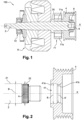
- FIG. 2 shows a partial exploded schematic view of a first embodiment of the drive assembly of the alternator 100.
- the pulley 4 has a bore 41 for the passage of the rotor shaft 2.
- the bore 41 comprises a first wall 41a and a second wall 41b which extend axially in the extension of one another.
- the second wall 41b is cylindrical in shape.
- the rotor shaft 2 comprises a first surface 21 and a second surface 22 which extend axially in the extension of one another.
- the second surface 22 extends over the entire circumference of the shaft 2 and has a general shape complementary to that of the second wall 41b of the bore 41.
- the second surface 22 is cylindrical in shape.
- the second surface 22 is provided with a knurling having a diameter A substantially greater than the diameter A' of the second wall 41b of the bore 41.
- the pulley 4 is forcefully mounted on the rotor shaft 2 by means of the knurling .
- the knurling contributes to blocking the pulley 4 in rotation and in translation on the shaft 2.
- the diameter A of the knurling is preferably between 1 and 1.1 times the diameter A' of the second wall 41b of the bore 41.
- the first surface 21 cooperates with the first wall 41a of the bore to center the pulley around the shaft 2.
- knurling alone does not allow appropriately align the center of the pulley 4 with the longitudinal axis is confused with that of shaft 2 and pulley 4 then has no unbalance.
- the first surface 21 of the shaft 2 and the first wall 41a of the bore 41 have a cylindrical shape of the same diameter B.
- the first surface 21 of the shaft 2 and the first wall 41a of the bore 41 can both have one or more flats formed parallel to the longitudinal axis X and arranged circumferentially.
- the first surface 21 of the shaft 2 and the first wall 41a of the bore 41 have a longitudinally truncated cylindrical shape, which makes it possible to improve the locking in rotation of the pulley 4 on the rotor shaft 2.
- the first centering surface 21 extends over a length preferably between 1 and 3 times the length of the surface 22. It should be noted that the surface 21 forms a functional guiding zone between the shaft and the pulley.
- the knurling extends over a length preferably between 0.1 and 1 time the diameter of the shaft 2.
- the diameter B of the first surface 21 of the shaft 2 is greater than the diameter A of the knurling.
- the diameter B of the first surface 21 of the rotor shaft is then preferably between 1 and 2 times the diameter B of the knurling.
- the knurling is placed in front of the first surface 21.
- the second wall 41b of the bore 41 is placed in front of the first wall 41a of the bore 41.
- FIG. 3 shows a second embodiment, which is not part of the invention, in which the diameter B of the first surface 21 of the shaft 2 is less than the diameter A of the knurling.
- the diameter A of the first surface of the rotor shaft is then preferably between 0.5 and 1 times the diameter B of the knurling.
- the knurling is arranged behind the first surface 21.
- the second wall 41b of the bore 41 is arranged behind the first wall 41a of the bore 41.
- the first surface 21 of the rotor shaft 2 and the first wall 41a of the bore 41 each have a surface condition comprising asperities having dimensions less than a characteristic dimension.
- the first surface 21 and the first wall 41a are visually devoid of roughness.
- the first surface 21 and the first wall 41a are homogeneous to the touch.
- the first surface 21 of the rotor shaft 2 and the first wall 41a of the bore 41 are configured to be substantially smooth so as to facilitate the centering of the pulley 4 on the shaft 2.
- the first surface 21 of the shaft allowing the centering of the pulley 4 may in particular comprise a first part and a second part arranged on either side of the knurling.
- the pulley could also be replaced by a sprocket and the torque transmission system, for example a chain.
Landscapes
- Engineering & Computer Science (AREA)
- General Engineering & Computer Science (AREA)
- Mechanical Engineering (AREA)
- Connection Of Motors, Electrical Generators, Mechanical Devices, And The Like (AREA)
- Iron Core Of Rotating Electric Machines (AREA)
Description
- Le domaine technique de l'invention est celui des machines électriques tournantes, telles qu'un alternateur ou un alterno-démarreur, équipant des véhicules automobiles à moteur thermique.
- L'invention concerne un ensemble d'entraînement d'une machine électrique tournante comportant un arbre de rotor et une pièce de liaison (par exemple, une poulie ou un pignon) permettant une liaison entre l'arbre et le système de transmission du couple (par exemple, une courroie ou une chaîne).
- Un véhicule automobile à moteur thermique est équipé d'un alternateur qui a pour fonction de transformer de l'énergie mécanique provenant du moteur en énergie électrique dans le but notamment de recharger la batterie du véhicule et d'alimenter électriquement le réseau de bord du véhicule.
- L'alternateur est une machine électrique tournante comprenant un arbre sur lequel est montée une poulie. Cette poulie est reliée par une courroie à une autre poulie montée sur le vilebrequin du moteur. La courroie transmet le mouvement de rotation du vilebrequin à l'arbre de l'alternateur.
- Il est connu de bloquer la poulie en rotation autour de l'arbre au moyen d'un écrou de serrage. Cependant, l'effort de serrage produit par ce moyen de fixation peut ne pas être suffisant pour maintenir la poulie solidaire de l'arbre. En effet, lorsque l'alternateur est en fonctionnement, l'écrou est susceptible de se desserrer, en particulier lorsque la poulie est soumise à un couple élevé.
- Il apparaît donc un besoin d'améliorer le blocage en rotation de la poulie autour de l'arbre.
- Des exemples sont divulgués dans :
FR2898068 WO03081063 EP14834936 JP2004336965 JP2000283264 - L'invention propose une solution pour améliorer le maintien d'une pièce de liaison (par exemple, une poulie ou un pignon) permettant une liaison entre l'arbre et le système de transmission du couple (par exemple, une courroie ou une chaîne), ladite pièce de liaison étant montée solidaire en rotation et en translation sur un arbre.
- L'invention concerne un ensemble d'entraînement d'une machine électrique tournante pour un véhicule automobile selon la revendication 1.
- Ainsi, grâce à l'invention, il est possible d'assurer le blocage en rotation de la pièce de liaison sur l'arbre par l'intermédiaire du moletage tout en garantissant que la pièce de liaison soit montée de manière centrée.
- L'ensemble d'entraînement selon le premier aspect de l'invention peut également comporter une ou plusieurs caractéristiques selon les revendications dépendantes.
- Un deuxième aspect de l'invention concerne une machine électrique tournante comprenant un ensemble d'entraînement selon l'invention.
- L'invention et ses différentes applications seront mieux comprises à la lecture de la description qui suit et à l'examen des figures qui l'accompagnent, parmi lesquelles :
- la
figure 1 est une vue schématique partielle en coupe longitudinale d'un mode de réalisation d'un alternateur qui ne fait pas partie de l'invention; - la
figure 2 est une vue schématique partielle éclaté de l'invention; - la
figure 3 est une vue schématique partielle éclaté d'un deuxième mode de réalisation de l'ensemble d'entraînement qui ne fait pas partie de l'invention; - Les figures ne sont présentées qu'à titre indicatif et nullement limitatif de l'invention.
- Pour plus de clarté, les éléments identiques ou similaires sont repérés par des signes de référence identiques sur toutes les figures.
- Un alternateur 100 va maintenant être décrit, en référence à la
figure 1 . L'alternateur est une machine électrique tournante configurée pour transformer de l'énergie mécanique provenant d'un moteur thermique de véhicule automobile en énergie électrique. Selon un autre mode de réalisation de l'invention, la machine électrique tournante peut être un alterno-démarreur. - L'alternateur 100 comporte un ensemble d'entraînement comprenant un arbre de rotor 2 s'étendant selon un axe longitudinal X et une pièce de liaison permettant une liaison entre l'arbre et le système de transmission du couple 4 montée solidaire en rotation et en translation sur une extrémité avant de l'arbre 2.
- Cette pièce de liaison est formée dans l'exemple illustré par une poulie. Dans ce cas, le système de transmission du couple est formé par une courroie.
- Dans une mise en oeuvre différente non illustrée, cette pièce de liaison peut être formée par un pignon. Dans ce cas, le système de transmission du couple est formé par une chaine. Pour la suite de la description, l'exemple choisi est celui d'une poulie. Mais il est entendu, que cette poulie pourrait être remplacée par un pignon.
- Dans l'ensemble de la description et dans les revendications, les termes « avant », « arrière », « devant » et « derrière » sont utilisés pour caractériser des positions relatives dans le référentiel de l'alternateur 100, l'avant de l'alternateur 100 correspondant à l'extrémité de l'arbre 2 munie de la poulie 4.
- L'alternateur 100 comporte également un rotor 6 monté solidaire en rotation sur l'arbre 2, et un stator (non représenté) entourant le rotor 6. Le stator est porté par un carter (non représenté) monté à rotation par rapport à l'arbre 2 au moyen d'un roulement à billes avant 71 et d'un roulement à billes arrière 72 disposés de part et d'autre du rotor 6.
- L'arbre 2 comporte une butée 25 disposée entre le rotor 6 et le roulement avant 71. Le roulement avant 71 comporte une piste de roulement interne 71a en contact avec l'arbre 2 et une piste de roulement externe 71b. La piste interne 71a du roulement avant 71 est en appui sur la butée 25 et la poulie 4 est maintenu serrée contre la piste interne 71a au moyen d'un écrou de serrage 8. L'extrémité avant de l'arbre 2 comporte une empreinte 9 destinée à recevoir une clé permettant de bloquer l'arbre 2 en rotation lors de l'assemblage de la poulie 4.
- Le moteur thermique comporte un vilebrequin animé d'un mouvement de rotation. La poulie 4 est destinée à être entraînée en rotation par une courroie reliant mécaniquement la poulie 4 de l'alternateur 100 à une poulie montée solidaire en rotation sur le vilebrequin. Le mouvement de rotation du vilebrequin est transmis à la poulie 4, à l'arbre 2 et au rotor 6, ces éléments étant montés solidaire en rotation.
- La
figure 2 montre une vue schématique partielle éclatée d'un premier mode de réalisation de l'ensemble d'entraînement de l'alternateur 100. La poulie 4 comporte un alésage 41 pour le passage de l'arbre de rotor 2. L'alésage 41 comporte une première paroi 41a et une deuxième paroi 41b qui s'étendent axialement dans le prolongement l'une de l'autre. La deuxième paroi 41b est de forme cylindrique. - L'arbre de rotor 2 comporte une première surface 21 et une deuxième surface 22 qui s'étendent axialement dans le prolongement l'une de l'autre. La deuxième surface 22 s'étend sur toute la circonférence de l'arbre 2 et présente une forme générale complémentaire à celle de la deuxième paroi 41b de l'alésage 41. La deuxième surface 22 est de forme cylindrique.
- Comme illustré sur la
figure 2 , la deuxième surface 22 est munie d'un moletage présentant un diamètre A sensiblement supérieur au diamètre A' de la deuxième paroi 41b de l'alésage 41. La poulie 4 est montée en force sur l'arbre de rotor 2 au moyen du moletage. En complément de l'écrou de serrage 8, le moletage contribue à bloquer en rotation et en translation la poulie 4 sur l'arbre 2. Le diamètre A du moletage est de préférence compris entre 1 et 1,1 fois le diamètre A' de la deuxième paroi 41b de l'alésage 41. - Lors de l'assemblage de la poulie 4 sur l'arbre 2, la première surface 21 coopère avec la première paroi 41a de l'alésage pour centrer la poulie autour de l'arbre 2. En effet, le moletage seul ne permet pas d'aligner de manière appropriée le centre de la poulie 4 avec l'axe longitudinal X qui correspond à l'axe de rotation de l'arbre 2. Grâce à la coopération de ces surfaces de centrage, l'axe de rotation de la poulie 4 est confondu avec celui de l'arbre 2 et la poulie 4 n'a alors pas de balourd.
- Dans le mode de réalisation de la
figure 2 , la première surface 21 de l'arbre 2 et la première paroi 41a de l'alésage 41 ont une forme cylindrique de même diamètre B. Dans une alternative, qui ne fait pas partie de l'invention, la première surface 21 de l'arbre 2 et la première paroi 41a de l'alésage 41 peuvent toutes les deux présenter un ou plusieurs méplats formés parallèlement à l'axe longitudinal X et disposés de manière circonférentielle. Dans ce cas, la première surface 21 de l'arbre 2 et la première paroi 41a de l'alésage 41 ont une forme cylindrique tronquée longitudinalement, ce qui permet d'améliorer le blocage en rotation de la poulie 4 sur l'arbre de rotor 2. - La première surface 21 de centrage s'étend sur une longueur de préférence comprise entre 1 et 3 fois la longueur de la surface 22. Il convient de noter que la surface 21 forme une zone fonctionnelle de guidage entre l'arbre et la poulie.
- Le moletage s'étend sur une longueur de préférence comprise entre 0,1 et 1 fois le diamètre de l'arbre 2.
- Dans le mode de réalisation de la
figure 2 , le diamètre B de la première surface 21 de l'arbre 2 est supérieur au diamètre A du moletage. Le diamètre B de la première surface 21 de l'arbre de rotor est alors de préférence compris entre 1 et 2 fois le diamètre B du moletage. Dans ce cas, le moletage est disposé devant la première surface 21. De manière complémentaire, la deuxième paroi 41b de l'alésage 41 est disposée devant la première paroi 41a de l'alésage 41. - La
figure 3 montre un deuxième mode de réalisation, qui ne fait pas partie de l'invention, dans lequel le diamètre B de la première surface 21 de l'arbre 2 est inférieur au diamètre A du moletage. Le diamètre A de la première surface de l'arbre de rotor est alors de préférence compris entre 0,5 et 1 fois le diamètre B du moletage Dans ce cas, le moletage est disposé derrière la première surface 21. De manière complémentaire, la deuxième paroi 41b de l'alésage 41 est disposée derrière la première paroi 41a de l'alésage 41. - Avantageusement, la première surface 21 de l'arbre de rotor 2 et la première paroi 41a de l'alésage 41 présentent chacune un état de surface comportant des aspérités ayant des dimensions inférieures à une dimension caractéristique. Selon un mode de réalisation, la première surface 21 et la première paroi 41a sont visuellement dépourvues d'aspérités. Selon un autre mode de réalisation, la première surface 21 et la première paroi 41a sont homogènes au toucher.
- Selon l'invention, la première surface 21 de l'arbre de rotor 2 et la première paroi 41a de l'alésage 41 sont configurées pour être sensiblement lisses de manière à faciliter le centrage de la poulie 4 sur l'arbre 2.
- Naturellement, l'invention n'est pas limitée aux modes de réalisations décrits en référence à la
figure 2 et des variantes pourraient être envisagées sans sortir du cadre de l'étendue de la protection définie par les revendications. - La première surface 21 de l'arbre permettant le centrage de la poulie 4 peut notamment comporter une première partie et une deuxième partie disposées de part et d'autre du moletage. En outre, la poulie pourrait également être remplacée par un pignon et le système de transmission du couple, par exemple une chaîne.
Claims (5)
- Ensemble d'entraînement d'une machine électrique tournante (100) pour un véhicule automobile, l'ensemble d'entraînement comportant un arbre de rotor (2) s'étendant selon un axe longitudinal (X) et une pièce de liaison (4) permettant une liaison entre l'arbre de rotor (2) et le système de transmission du couple comportant un alésage (41) pour le passage de l'arbre de rotor (2), l'alésage (41) comportant une première paroi (41a) s'étendant axialement et une deuxième paroi (41b) cylindrique s'étendant axialement dans le prolongement de la première paroi (41a), et l'arbre de rotor (2) comportant:- une première surface (21) s'étendant axialement et coopérant avec la première paroi (41a) de l'alésage (41) pour le centrage de la pièce de liaison (4) autour de l'arbre de rotor (2); et- une deuxième surface (22) cylindrique s'étendant axialement et munie d'un moletage présentant un diamètre (A) supérieur au diamètre (A') de la deuxième paroi (41b) de l'alésage (41), la pièce de liaison (4) étant montée en force sur l'arbre de roto (2) au moyen du moletageen ce que la première surface (21) de l'arbre de rotor (2) et la première paroi (41a) de l'alésage (41) sont des surfaces cylindriques présentant un même diamètre (B),en ce que la pièce de liaison (4) est montée au niveau d'une première extrémité de l'arbre de rotor (2),en ce que la première surface (21) de l'arbre de rotor (2) et la première paroi (41a) de l'alésage (41) sont configurées pour être sensiblement lisses de manière à faciliter le centrage de la pièce de liaison (4) sur l'arbre de rotor (2),l'ensable d'entraînement étant caractériseen ce que le diamètre (B) de la première surface (21) de l'arbre de rotor (2) est supérieurau diamètre (A) du moletage, le moletage étant disposé entre la première surface (21) etla première extrémité de l'arbre de rotor (2) et,en ce que le moletage est constitué d'une multitude de saillies qui viennent creuser des sillons dans la deuxième paroi (41b) de l'alésage (41) lorsque la pièce de liaison (4) est emmanchée en force sur l'arbre de rotor (2).
- Ensemble selon la revendication précédente, caractérisé en ce que le diamètre (B) de la première surface (21) de l'arbre de rotor (2) est compris entre 1 et 2 fois le diamètre (A) du moletage.
- Ensemble selon l'une quelconque des revendications précédentes selon lequel la première surface (21) de centrage s'étend sur une longueur de préférence comprise entre 1 et 3 fois la longueur de la deuxième surface (22).
- Ensemble selon l'une quelconque des revendications précédentes selon lequel le moletage s'étend sur une longueur de préférence comprise entre 0,1 et 1 fois le diamètre de l'arbre de rotor (2).
- Machine électrique tournante (100) caractérisée en ce qu'elle comporte un ensemble d'entraînement selon l'une quelconque des revendications 1 à 4.
Applications Claiming Priority (2)
| Application Number | Priority Date | Filing Date | Title |
|---|---|---|---|
| FR1755923A FR3068408B1 (fr) | 2017-06-28 | 2017-06-28 | Ensemble d'entrainement d'une machine electrique tournante pour un vehicule automobile |
| PCT/EP2018/067312 WO2019002402A1 (fr) | 2017-06-28 | 2018-06-27 | Ensemble d'entrainement d'une machine electrique tournante pour un vehicule automobile |
Publications (2)
| Publication Number | Publication Date |
|---|---|
| EP3645903A1 EP3645903A1 (fr) | 2020-05-06 |
| EP3645903B1 true EP3645903B1 (fr) | 2024-01-10 |
Family
ID=59859282
Family Applications (1)
| Application Number | Title | Priority Date | Filing Date |
|---|---|---|---|
| EP18740118.7A Active EP3645903B1 (fr) | 2017-06-28 | 2018-06-27 | Ensemble d'entrainement d'une machine electrique tournante pour un vehicule automobile |
Country Status (7)
| Country | Link |
|---|---|
| US (1) | US11353064B2 (fr) |
| EP (1) | EP3645903B1 (fr) |
| JP (2) | JP2020525739A (fr) |
| KR (1) | KR102326798B1 (fr) |
| CN (1) | CN110869630B (fr) |
| FR (1) | FR3068408B1 (fr) |
| WO (1) | WO2019002402A1 (fr) |
Families Citing this family (9)
| Publication number | Priority date | Publication date | Assignee | Title |
|---|---|---|---|---|
| JP7149034B2 (ja) | 2018-01-17 | 2022-10-06 | 三菱電機株式会社 | 回転電機 |
| EP3824198B1 (fr) * | 2018-07-17 | 2025-04-09 | Sew-Eurodrive GmbH & Co. KG | Liaison arbre-moyeu et procédè de réalisation d'une liaison arbre-moyeu |
| WO2020225582A1 (fr) * | 2019-05-07 | 2020-11-12 | 日産自動車株式会社 | Machine dynamoélectrique |
| DE102020111679A1 (de) * | 2020-04-29 | 2021-11-04 | Valeo Siemens Eautomotive Germany Gmbh | Welle, Umformwerkzeug, Herstellungsverfahren und Rotor für eine elektrische Maschine |
| US12498021B2 (en) * | 2022-08-04 | 2025-12-16 | Bpb Mediterranea S.A. | Tensioning sprocket to be applied to the row of a corn header |
| US12146561B2 (en) * | 2022-10-19 | 2024-11-19 | Todd C Chalmers | Electric motor and belt transmission shaft system |
| FR3157486B1 (fr) * | 2023-12-20 | 2026-03-06 | Valeo Embrayages | Machine électrique pour engin de mobilité |
| FR3157494B1 (fr) * | 2023-12-20 | 2025-11-07 | Valeo Embrayages | Arbre de sortie de machine électrique |
| DE102024122547A1 (de) * | 2024-08-07 | 2026-02-12 | Bayerische Motoren Werke Aktiengesellschaft | Verfahren zum Herstellen einer Befestigungsanordnung, Befestigungsanordnung sowie Kraftfahrzeugbaugruppe mit der Befestigungsanordnung und Kraftfahrzeug |
Citations (4)
| Publication number | Priority date | Publication date | Assignee | Title |
|---|---|---|---|---|
| JP2000283264A (ja) * | 1999-01-28 | 2000-10-13 | Seiko Epson Corp | 歯車および歯車装置 |
| WO2003081063A2 (fr) * | 2002-03-22 | 2003-10-02 | Valeo Equipements Electriques Moteur | Procede d'assemblage d'une poulie d'alternateur de vehicule automobile et alternateur de vehicule automobile comportant un tel assemblage |
| JP2004336965A (ja) * | 2003-05-12 | 2004-11-25 | Denso Corp | 回転電機の回転子および磁石式交流発電機の回転子 |
| EP3032102A1 (fr) * | 2013-08-09 | 2016-06-15 | Aisin Seiki Kabushiki Kaisha | Rotor interne de pompe hydraulique |
Family Cites Families (14)
| Publication number | Priority date | Publication date | Assignee | Title |
|---|---|---|---|---|
| JPH0229262Y2 (fr) * | 1986-09-30 | 1990-08-06 | ||
| DE3738924A1 (de) | 1987-11-17 | 1989-06-01 | Swf Auto Electric Gmbh | Getriebeteil fuer eine wischanlage von kraftfahrzeugen und verfahren zu dessen herstellen |
| US5275577A (en) * | 1992-08-10 | 1994-01-04 | Emerson Electric Co. | Pulley retention mechanism |
| DE4345099A1 (de) * | 1993-12-31 | 1995-07-06 | Alpha Getriebebau Gmbh | Wellen-Befestigung |
| DE10137025C1 (de) * | 2001-07-30 | 2002-12-05 | Sew Eurodrive Gmbh & Co | Baureihe von Wellen und Verfahren zur Fertigung |
| JP2003061307A (ja) * | 2001-08-17 | 2003-02-28 | Mitsubishi Electric Corp | 回転電機 |
| DE10316155B4 (de) * | 2002-05-24 | 2006-04-20 | Sew-Eurodrive Gmbh & Co. Kg | Welle, Baureihe von Wellen und Verfahren zur Fertigung |
| FR2898068B1 (fr) | 2006-03-01 | 2009-01-16 | Valeo Equip Electr Moteur | Dispositif d'assemblage d'un organe d'entrainement avec un arbre accouple au rotor d'une machine electrique tournante |
| JP4179516B2 (ja) | 2006-08-01 | 2008-11-12 | 株式会社ハーモニック・エイディ | 歯車の締結方法および締結構造 |
| JP5067416B2 (ja) | 2009-12-03 | 2012-11-07 | 三菱電機株式会社 | 回転電機 |
| JP5111563B2 (ja) | 2010-06-01 | 2013-01-09 | 三菱電機株式会社 | 回転電機 |
| CN103836083A (zh) | 2012-11-21 | 2014-06-04 | 天津轻工职业技术学院 | 一种新型对数螺线型面无键联接孔的设计 |
| KR20150057784A (ko) * | 2013-11-20 | 2015-05-28 | 엘지이노텍 주식회사 | 벨트 구동형 시동 발전기 |
| CN106567918A (zh) * | 2016-10-20 | 2017-04-19 | 安徽江淮汽车集团股份有限公司 | 齿轮及其加工方法、齿轮轴、齿轮传动结构和装配方法 |
-
2017
- 2017-06-28 FR FR1755923A patent/FR3068408B1/fr active Active
-
2018
- 2018-06-27 JP JP2019572614A patent/JP2020525739A/ja active Pending
- 2018-06-27 CN CN201880043947.7A patent/CN110869630B/zh active Active
- 2018-06-27 KR KR1020197038410A patent/KR102326798B1/ko active Active
- 2018-06-27 US US16/625,062 patent/US11353064B2/en active Active
- 2018-06-27 WO PCT/EP2018/067312 patent/WO2019002402A1/fr not_active Ceased
- 2018-06-27 EP EP18740118.7A patent/EP3645903B1/fr active Active
-
2023
- 2023-02-08 JP JP2023017523A patent/JP2023055928A/ja active Pending
Patent Citations (4)
| Publication number | Priority date | Publication date | Assignee | Title |
|---|---|---|---|---|
| JP2000283264A (ja) * | 1999-01-28 | 2000-10-13 | Seiko Epson Corp | 歯車および歯車装置 |
| WO2003081063A2 (fr) * | 2002-03-22 | 2003-10-02 | Valeo Equipements Electriques Moteur | Procede d'assemblage d'une poulie d'alternateur de vehicule automobile et alternateur de vehicule automobile comportant un tel assemblage |
| JP2004336965A (ja) * | 2003-05-12 | 2004-11-25 | Denso Corp | 回転電機の回転子および磁石式交流発電機の回転子 |
| EP3032102A1 (fr) * | 2013-08-09 | 2016-06-15 | Aisin Seiki Kabushiki Kaisha | Rotor interne de pompe hydraulique |
Also Published As
| Publication number | Publication date |
|---|---|
| CN110869630B (zh) | 2023-01-10 |
| FR3068408A1 (fr) | 2019-01-04 |
| WO2019002402A1 (fr) | 2019-01-03 |
| EP3645903A1 (fr) | 2020-05-06 |
| KR20200014819A (ko) | 2020-02-11 |
| JP2020525739A (ja) | 2020-08-27 |
| JP2023055928A (ja) | 2023-04-18 |
| US20200149591A1 (en) | 2020-05-14 |
| KR102326798B1 (ko) | 2021-11-15 |
| CN110869630A (zh) | 2020-03-06 |
| FR3068408B1 (fr) | 2021-03-19 |
| US11353064B2 (en) | 2022-06-07 |
Similar Documents
| Publication | Publication Date | Title |
|---|---|---|
| EP3645903B1 (fr) | Ensemble d'entrainement d'une machine electrique tournante pour un vehicule automobile | |
| FR2929889A1 (fr) | Moyeu motorise pour un vehicule automobile a traction electrique | |
| FR2884068A1 (fr) | Rotor de machine electrique tournante comportant un manchon intermediaire interpose entre l'arbre et les roues polaires et procede de realisation du rotor. | |
| EP4384726B1 (fr) | Accouplement d'arbres rotatifs permettant un déplacement axial au moyen d'éléments roulants | |
| FR2929462A1 (fr) | Arbre de rotor destine a assurer une liaison mecanique avec un reducteur de vitesses d'une machine electrique tournante | |
| EP3836368A1 (fr) | Machine électrique tournante comportant un organe élastique | |
| FR2887377A1 (fr) | Demarreur de moteur a combustion interne d'automobile et machine electrique tournante concus pour resister aux effets de vibrations | |
| FR2986674A1 (fr) | Machine electrique et son procede de montage | |
| FR2979039A1 (fr) | Machine electrique et son procede de montage | |
| WO2017134376A1 (fr) | Ensemble poulie pour une machine electrique tournante | |
| FR3068540A1 (fr) | Flasque de protection destine a etre assemble sur une poulie d'une machine electrique tournante | |
| FR3082572A1 (fr) | Dispositif d'arret axial entre deux pieces | |
| FR3157287A1 (fr) | Agencement pour véhicule automobile à motorisation électrique ou hybride | |
| FR3076334B1 (fr) | Ensemble poulie a embrayage a limitation de choc ameliore | |
| FR3076335B1 (fr) | Ensemble poulie a limitation de choc a frottement ameliore | |
| FR2898654A1 (fr) | Organe d'entrainement visse pour machine electrique tournante et son outil de vissage associe | |
| FR3154559A1 (fr) | Motoréducteur et procédé d’assemblage associé | |
| WO2024235693A1 (fr) | Ensemble d'elements d'un groupe motopropulseur | |
| FR3156260A1 (fr) | Organe de transfert de couple d'une machine rotative | |
| EP3464950A1 (fr) | Démarreur muni d'un pignon ayant au moins une dent profilée | |
| WO2025099087A1 (fr) | Agencement pour véhicule automobile à motorisation électrique ou hybride et moteur électrique pour un tel agencement | |
| FR3124036A1 (fr) | Machine électrique tournante à flux axial multiple ayant une configuration creuse | |
| WO2024074653A1 (fr) | Frein de stationnement et machine electrique comportant un tel frein | |
| WO2006111657A1 (fr) | Alternateur comprenant un roulement à bride de fixation | |
| FR2951883A1 (fr) | Moteur d'essuie-glace |
Legal Events
| Date | Code | Title | Description |
|---|---|---|---|
| STAA | Information on the status of an ep patent application or granted ep patent |
Free format text: STATUS: UNKNOWN |
|
| STAA | Information on the status of an ep patent application or granted ep patent |
Free format text: STATUS: THE INTERNATIONAL PUBLICATION HAS BEEN MADE |
|
| PUAI | Public reference made under article 153(3) epc to a published international application that has entered the european phase |
Free format text: ORIGINAL CODE: 0009012 |
|
| STAA | Information on the status of an ep patent application or granted ep patent |
Free format text: STATUS: REQUEST FOR EXAMINATION WAS MADE |
|
| 17P | Request for examination filed |
Effective date: 20191202 |
|
| AK | Designated contracting states |
Kind code of ref document: A1 Designated state(s): AL AT BE BG CH CY CZ DE DK EE ES FI FR GB GR HR HU IE IS IT LI LT LU LV MC MK MT NL NO PL PT RO RS SE SI SK SM TR |
|
| AX | Request for extension of the european patent |
Extension state: BA ME |
|
| DAV | Request for validation of the european patent (deleted) | ||
| DAX | Request for extension of the european patent (deleted) | ||
| STAA | Information on the status of an ep patent application or granted ep patent |
Free format text: STATUS: EXAMINATION IS IN PROGRESS |
|
| 17Q | First examination report despatched |
Effective date: 20201126 |
|
| GRAP | Despatch of communication of intention to grant a patent |
Free format text: ORIGINAL CODE: EPIDOSNIGR1 |
|
| STAA | Information on the status of an ep patent application or granted ep patent |
Free format text: STATUS: GRANT OF PATENT IS INTENDED |
|
| INTG | Intention to grant announced |
Effective date: 20230306 |
|
| P01 | Opt-out of the competence of the unified patent court (upc) registered |
Effective date: 20230528 |
|
| GRAJ | Information related to disapproval of communication of intention to grant by the applicant or resumption of examination proceedings by the epo deleted |
Free format text: ORIGINAL CODE: EPIDOSDIGR1 |
|
| STAA | Information on the status of an ep patent application or granted ep patent |
Free format text: STATUS: EXAMINATION IS IN PROGRESS |
|
| GRAP | Despatch of communication of intention to grant a patent |
Free format text: ORIGINAL CODE: EPIDOSNIGR1 |
|
| STAA | Information on the status of an ep patent application or granted ep patent |
Free format text: STATUS: GRANT OF PATENT IS INTENDED |
|
| INTC | Intention to grant announced (deleted) | ||
| INTG | Intention to grant announced |
Effective date: 20230810 |
|
| GRAS | Grant fee paid |
Free format text: ORIGINAL CODE: EPIDOSNIGR3 |
|
| GRAA | (expected) grant |
Free format text: ORIGINAL CODE: 0009210 |
|
| STAA | Information on the status of an ep patent application or granted ep patent |
Free format text: STATUS: THE PATENT HAS BEEN GRANTED |
|
| AK | Designated contracting states |
Kind code of ref document: B1 Designated state(s): AL AT BE BG CH CY CZ DE DK EE ES FI FR GB GR HR HU IE IS IT LI LT LU LV MC MK MT NL NO PL PT RO RS SE SI SK SM TR |
|
| REG | Reference to a national code |
Ref country code: GB Ref legal event code: FG4D Free format text: NOT ENGLISH |
|
| REG | Reference to a national code |
Ref country code: CH Ref legal event code: EP |
|
| REG | Reference to a national code |
Ref country code: DE Ref legal event code: R096 Ref document number: 602018063967 Country of ref document: DE |
|
| REG | Reference to a national code |
Ref country code: IE Ref legal event code: FG4D Free format text: LANGUAGE OF EP DOCUMENT: FRENCH |
|
| REG | Reference to a national code |
Ref country code: LT Ref legal event code: MG9D |
|
| REG | Reference to a national code |
Ref country code: NL Ref legal event code: MP Effective date: 20240110 |
|
| REG | Reference to a national code |
Ref country code: AT Ref legal event code: MK05 Ref document number: 1649108 Country of ref document: AT Kind code of ref document: T Effective date: 20240110 |
|
| PG25 | Lapsed in a contracting state [announced via postgrant information from national office to epo] |
Ref country code: NL Free format text: LAPSE BECAUSE OF FAILURE TO SUBMIT A TRANSLATION OF THE DESCRIPTION OR TO PAY THE FEE WITHIN THE PRESCRIBED TIME-LIMIT Effective date: 20240110 |
|
| PG25 | Lapsed in a contracting state [announced via postgrant information from national office to epo] |
Ref country code: NL Free format text: LAPSE BECAUSE OF FAILURE TO SUBMIT A TRANSLATION OF THE DESCRIPTION OR TO PAY THE FEE WITHIN THE PRESCRIBED TIME-LIMIT Effective date: 20240110 |
|
| PG25 | Lapsed in a contracting state [announced via postgrant information from national office to epo] |
Ref country code: IS Free format text: LAPSE BECAUSE OF FAILURE TO SUBMIT A TRANSLATION OF THE DESCRIPTION OR TO PAY THE FEE WITHIN THE PRESCRIBED TIME-LIMIT Effective date: 20240510 |
|
| PG25 | Lapsed in a contracting state [announced via postgrant information from national office to epo] |
Ref country code: LT Free format text: LAPSE BECAUSE OF FAILURE TO SUBMIT A TRANSLATION OF THE DESCRIPTION OR TO PAY THE FEE WITHIN THE PRESCRIBED TIME-LIMIT Effective date: 20240110 |
|
| PG25 | Lapsed in a contracting state [announced via postgrant information from national office to epo] |
Ref country code: GR Free format text: LAPSE BECAUSE OF FAILURE TO SUBMIT A TRANSLATION OF THE DESCRIPTION OR TO PAY THE FEE WITHIN THE PRESCRIBED TIME-LIMIT Effective date: 20240411 |
|
| PG25 | Lapsed in a contracting state [announced via postgrant information from national office to epo] |
Ref country code: HR Free format text: LAPSE BECAUSE OF FAILURE TO SUBMIT A TRANSLATION OF THE DESCRIPTION OR TO PAY THE FEE WITHIN THE PRESCRIBED TIME-LIMIT Effective date: 20240110 Ref country code: RS Free format text: LAPSE BECAUSE OF FAILURE TO SUBMIT A TRANSLATION OF THE DESCRIPTION OR TO PAY THE FEE WITHIN THE PRESCRIBED TIME-LIMIT Effective date: 20240410 |
|
| PG25 | Lapsed in a contracting state [announced via postgrant information from national office to epo] |
Ref country code: ES Free format text: LAPSE BECAUSE OF FAILURE TO SUBMIT A TRANSLATION OF THE DESCRIPTION OR TO PAY THE FEE WITHIN THE PRESCRIBED TIME-LIMIT Effective date: 20240110 |
|
| PG25 | Lapsed in a contracting state [announced via postgrant information from national office to epo] |
Ref country code: AT Free format text: LAPSE BECAUSE OF FAILURE TO SUBMIT A TRANSLATION OF THE DESCRIPTION OR TO PAY THE FEE WITHIN THE PRESCRIBED TIME-LIMIT Effective date: 20240110 |
|
| PG25 | Lapsed in a contracting state [announced via postgrant information from national office to epo] |
Ref country code: RS Free format text: LAPSE BECAUSE OF FAILURE TO SUBMIT A TRANSLATION OF THE DESCRIPTION OR TO PAY THE FEE WITHIN THE PRESCRIBED TIME-LIMIT Effective date: 20240410 Ref country code: NO Free format text: LAPSE BECAUSE OF FAILURE TO SUBMIT A TRANSLATION OF THE DESCRIPTION OR TO PAY THE FEE WITHIN THE PRESCRIBED TIME-LIMIT Effective date: 20240410 Ref country code: LT Free format text: LAPSE BECAUSE OF FAILURE TO SUBMIT A TRANSLATION OF THE DESCRIPTION OR TO PAY THE FEE WITHIN THE PRESCRIBED TIME-LIMIT Effective date: 20240110 Ref country code: IS Free format text: LAPSE BECAUSE OF FAILURE TO SUBMIT A TRANSLATION OF THE DESCRIPTION OR TO PAY THE FEE WITHIN THE PRESCRIBED TIME-LIMIT Effective date: 20240510 Ref country code: HR Free format text: LAPSE BECAUSE OF FAILURE TO SUBMIT A TRANSLATION OF THE DESCRIPTION OR TO PAY THE FEE WITHIN THE PRESCRIBED TIME-LIMIT Effective date: 20240110 Ref country code: GR Free format text: LAPSE BECAUSE OF FAILURE TO SUBMIT A TRANSLATION OF THE DESCRIPTION OR TO PAY THE FEE WITHIN THE PRESCRIBED TIME-LIMIT Effective date: 20240411 Ref country code: ES Free format text: LAPSE BECAUSE OF FAILURE TO SUBMIT A TRANSLATION OF THE DESCRIPTION OR TO PAY THE FEE WITHIN THE PRESCRIBED TIME-LIMIT Effective date: 20240110 Ref country code: BG Free format text: LAPSE BECAUSE OF FAILURE TO SUBMIT A TRANSLATION OF THE DESCRIPTION OR TO PAY THE FEE WITHIN THE PRESCRIBED TIME-LIMIT Effective date: 20240110 Ref country code: AT Free format text: LAPSE BECAUSE OF FAILURE TO SUBMIT A TRANSLATION OF THE DESCRIPTION OR TO PAY THE FEE WITHIN THE PRESCRIBED TIME-LIMIT Effective date: 20240110 |
|
| RAP2 | Party data changed (patent owner data changed or rights of a patent transferred) |
Owner name: VALEO ELECTRIFICATION |
|
| PG25 | Lapsed in a contracting state [announced via postgrant information from national office to epo] |
Ref country code: PL Free format text: LAPSE BECAUSE OF FAILURE TO SUBMIT A TRANSLATION OF THE DESCRIPTION OR TO PAY THE FEE WITHIN THE PRESCRIBED TIME-LIMIT Effective date: 20240110 Ref country code: PT Free format text: LAPSE BECAUSE OF FAILURE TO SUBMIT A TRANSLATION OF THE DESCRIPTION OR TO PAY THE FEE WITHIN THE PRESCRIBED TIME-LIMIT Effective date: 20240510 |
|
| PG25 | Lapsed in a contracting state [announced via postgrant information from national office to epo] |
Ref country code: SE Free format text: LAPSE BECAUSE OF FAILURE TO SUBMIT A TRANSLATION OF THE DESCRIPTION OR TO PAY THE FEE WITHIN THE PRESCRIBED TIME-LIMIT Effective date: 20240110 Ref country code: PT Free format text: LAPSE BECAUSE OF FAILURE TO SUBMIT A TRANSLATION OF THE DESCRIPTION OR TO PAY THE FEE WITHIN THE PRESCRIBED TIME-LIMIT Effective date: 20240510 Ref country code: PL Free format text: LAPSE BECAUSE OF FAILURE TO SUBMIT A TRANSLATION OF THE DESCRIPTION OR TO PAY THE FEE WITHIN THE PRESCRIBED TIME-LIMIT Effective date: 20240110 Ref country code: LV Free format text: LAPSE BECAUSE OF FAILURE TO SUBMIT A TRANSLATION OF THE DESCRIPTION OR TO PAY THE FEE WITHIN THE PRESCRIBED TIME-LIMIT Effective date: 20240110 |
|
| PG25 | Lapsed in a contracting state [announced via postgrant information from national office to epo] |
Ref country code: DK Free format text: LAPSE BECAUSE OF FAILURE TO SUBMIT A TRANSLATION OF THE DESCRIPTION OR TO PAY THE FEE WITHIN THE PRESCRIBED TIME-LIMIT Effective date: 20240110 |
|
| REG | Reference to a national code |
Ref country code: DE Ref legal event code: R097 Ref document number: 602018063967 Country of ref document: DE |
|
| PG25 | Lapsed in a contracting state [announced via postgrant information from national office to epo] |
Ref country code: SM Free format text: LAPSE BECAUSE OF FAILURE TO SUBMIT A TRANSLATION OF THE DESCRIPTION OR TO PAY THE FEE WITHIN THE PRESCRIBED TIME-LIMIT Effective date: 20240110 |
|
| PG25 | Lapsed in a contracting state [announced via postgrant information from national office to epo] |
Ref country code: CZ Free format text: LAPSE BECAUSE OF FAILURE TO SUBMIT A TRANSLATION OF THE DESCRIPTION OR TO PAY THE FEE WITHIN THE PRESCRIBED TIME-LIMIT Effective date: 20240110 Ref country code: EE Free format text: LAPSE BECAUSE OF FAILURE TO SUBMIT A TRANSLATION OF THE DESCRIPTION OR TO PAY THE FEE WITHIN THE PRESCRIBED TIME-LIMIT Effective date: 20240110 |
|
| PG25 | Lapsed in a contracting state [announced via postgrant information from national office to epo] |
Ref country code: SK Free format text: LAPSE BECAUSE OF FAILURE TO SUBMIT A TRANSLATION OF THE DESCRIPTION OR TO PAY THE FEE WITHIN THE PRESCRIBED TIME-LIMIT Effective date: 20240110 |
|
| PG25 | Lapsed in a contracting state [announced via postgrant information from national office to epo] |
Ref country code: SM Free format text: LAPSE BECAUSE OF FAILURE TO SUBMIT A TRANSLATION OF THE DESCRIPTION OR TO PAY THE FEE WITHIN THE PRESCRIBED TIME-LIMIT Effective date: 20240110 Ref country code: SK Free format text: LAPSE BECAUSE OF FAILURE TO SUBMIT A TRANSLATION OF THE DESCRIPTION OR TO PAY THE FEE WITHIN THE PRESCRIBED TIME-LIMIT Effective date: 20240110 Ref country code: RO Free format text: LAPSE BECAUSE OF FAILURE TO SUBMIT A TRANSLATION OF THE DESCRIPTION OR TO PAY THE FEE WITHIN THE PRESCRIBED TIME-LIMIT Effective date: 20240110 Ref country code: EE Free format text: LAPSE BECAUSE OF FAILURE TO SUBMIT A TRANSLATION OF THE DESCRIPTION OR TO PAY THE FEE WITHIN THE PRESCRIBED TIME-LIMIT Effective date: 20240110 Ref country code: DK Free format text: LAPSE BECAUSE OF FAILURE TO SUBMIT A TRANSLATION OF THE DESCRIPTION OR TO PAY THE FEE WITHIN THE PRESCRIBED TIME-LIMIT Effective date: 20240110 Ref country code: CZ Free format text: LAPSE BECAUSE OF FAILURE TO SUBMIT A TRANSLATION OF THE DESCRIPTION OR TO PAY THE FEE WITHIN THE PRESCRIBED TIME-LIMIT Effective date: 20240110 |
|
| PLBE | No opposition filed within time limit |
Free format text: ORIGINAL CODE: 0009261 |
|
| STAA | Information on the status of an ep patent application or granted ep patent |
Free format text: STATUS: NO OPPOSITION FILED WITHIN TIME LIMIT |
|
| PG25 | Lapsed in a contracting state [announced via postgrant information from national office to epo] |
Ref country code: IT Free format text: LAPSE BECAUSE OF FAILURE TO SUBMIT A TRANSLATION OF THE DESCRIPTION OR TO PAY THE FEE WITHIN THE PRESCRIBED TIME-LIMIT Effective date: 20240110 |
|
| 26N | No opposition filed |
Effective date: 20241011 |
|
| PG25 | Lapsed in a contracting state [announced via postgrant information from national office to epo] |
Ref country code: IT Free format text: LAPSE BECAUSE OF FAILURE TO SUBMIT A TRANSLATION OF THE DESCRIPTION OR TO PAY THE FEE WITHIN THE PRESCRIBED TIME-LIMIT Effective date: 20240110 |
|
| PG25 | Lapsed in a contracting state [announced via postgrant information from national office to epo] |
Ref country code: MC Free format text: LAPSE BECAUSE OF FAILURE TO SUBMIT A TRANSLATION OF THE DESCRIPTION OR TO PAY THE FEE WITHIN THE PRESCRIBED TIME-LIMIT Effective date: 20240110 |
|
| REG | Reference to a national code |
Ref country code: CH Ref legal event code: PL |
|
| PG25 | Lapsed in a contracting state [announced via postgrant information from national office to epo] |
Ref country code: LU Free format text: LAPSE BECAUSE OF NON-PAYMENT OF DUE FEES Effective date: 20240627 |
|
| GBPC | Gb: european patent ceased through non-payment of renewal fee |
Effective date: 20240627 |
|
| PG25 | Lapsed in a contracting state [announced via postgrant information from national office to epo] |
Ref country code: IE Free format text: LAPSE BECAUSE OF NON-PAYMENT OF DUE FEES Effective date: 20240627 |
|
| PG25 | Lapsed in a contracting state [announced via postgrant information from national office to epo] |
Ref country code: SI Free format text: LAPSE BECAUSE OF FAILURE TO SUBMIT A TRANSLATION OF THE DESCRIPTION OR TO PAY THE FEE WITHIN THE PRESCRIBED TIME-LIMIT Effective date: 20240110 Ref country code: BE Free format text: LAPSE BECAUSE OF NON-PAYMENT OF DUE FEES Effective date: 20240630 Ref country code: CH Free format text: LAPSE BECAUSE OF NON-PAYMENT OF DUE FEES Effective date: 20240630 |
|
| PG25 | Lapsed in a contracting state [announced via postgrant information from national office to epo] |
Ref country code: GB Free format text: LAPSE BECAUSE OF NON-PAYMENT OF DUE FEES Effective date: 20240627 |
|
| REG | Reference to a national code |
Ref country code: BE Ref legal event code: MM Effective date: 20240630 |
|
| PGFP | Annual fee paid to national office [announced via postgrant information from national office to epo] |
Ref country code: DE Payment date: 20250617 Year of fee payment: 8 |
|
| PGFP | Annual fee paid to national office [announced via postgrant information from national office to epo] |
Ref country code: FR Payment date: 20250630 Year of fee payment: 8 |
|
| PG25 | Lapsed in a contracting state [announced via postgrant information from national office to epo] |
Ref country code: FI Free format text: LAPSE BECAUSE OF FAILURE TO SUBMIT A TRANSLATION OF THE DESCRIPTION OR TO PAY THE FEE WITHIN THE PRESCRIBED TIME-LIMIT Effective date: 20240110 |
|
| PG25 | Lapsed in a contracting state [announced via postgrant information from national office to epo] |
Ref country code: CY Free format text: LAPSE BECAUSE OF FAILURE TO SUBMIT A TRANSLATION OF THE DESCRIPTION OR TO PAY THE FEE WITHIN THE PRESCRIBED TIME-LIMIT; INVALID AB INITIO Effective date: 20180627 |
|
| PG25 | Lapsed in a contracting state [announced via postgrant information from national office to epo] |
Ref country code: HU Free format text: LAPSE BECAUSE OF FAILURE TO SUBMIT A TRANSLATION OF THE DESCRIPTION OR TO PAY THE FEE WITHIN THE PRESCRIBED TIME-LIMIT; INVALID AB INITIO Effective date: 20180627 |
|
| REG | Reference to a national code |
Ref country code: DE Ref legal event code: R081 Ref document number: 602018063967 Country of ref document: DE Owner name: VALEO ELECTRIFICATION, FR Free format text: FORMER OWNER: VALEO EQUIPEMENTS ELECTRIQUES MOTEUR, CRETEIL, FR |
|
| PLCP | Request for limitation filed |
Free format text: ORIGINAL CODE: EPIDOSNLIM1 |
|
| PLCQ | Request for limitation of patent found admissible |
Free format text: ORIGINAL CODE: 0009231 |