EP3643854A1 - Lastaufnahmevorrichtung - Google Patents
Lastaufnahmevorrichtung Download PDFInfo
- Publication number
- EP3643854A1 EP3643854A1 EP18201701.2A EP18201701A EP3643854A1 EP 3643854 A1 EP3643854 A1 EP 3643854A1 EP 18201701 A EP18201701 A EP 18201701A EP 3643854 A1 EP3643854 A1 EP 3643854A1
- Authority
- EP
- European Patent Office
- Prior art keywords
- load
- suspension device
- locking
- load suspension
- locking element
- Prior art date
- Legal status (The legal status is an assumption and is not a legal conclusion. Google has not performed a legal analysis and makes no representation as to the accuracy of the status listed.)
- Granted
Links
Images

Classifications
-
- E—FIXED CONSTRUCTIONS
- E04—BUILDING
- E04G—SCAFFOLDING; FORMS; SHUTTERING; BUILDING IMPLEMENTS OR AIDS, OR THEIR USE; HANDLING BUILDING MATERIALS ON THE SITE; REPAIRING, BREAKING-UP OR OTHER WORK ON EXISTING BUILDINGS
- E04G21/00—Preparing, conveying, or working-up building materials or building elements in situ; Other devices or measures for constructional work
- E04G21/14—Conveying or assembling building elements
- E04G21/142—Means in or on the elements for connecting same to handling apparatus
-
- B—PERFORMING OPERATIONS; TRANSPORTING
- B66—HOISTING; LIFTING; HAULING
- B66B—ELEVATORS; ESCALATORS OR MOVING WALKWAYS
- B66B11/00—Main component parts of lifts in, or associated with, buildings or other structures
- B66B11/0005—Constructional features of hoistways
-
- B—PERFORMING OPERATIONS; TRANSPORTING
- B66—HOISTING; LIFTING; HAULING
- B66C—CRANES; LOAD-ENGAGING ELEMENTS OR DEVICES FOR CRANES, CAPSTANS, WINCHES, OR TACKLES
- B66C1/00—Load-engaging elements or devices attached to lifting or lowering gear of cranes or adapted for connection therewith for transmitting lifting forces to articles or groups of articles
- B66C1/10—Load-engaging elements or devices attached to lifting or lowering gear of cranes or adapted for connection therewith for transmitting lifting forces to articles or groups of articles by mechanical means
- B66C1/62—Load-engaging elements or devices attached to lifting or lowering gear of cranes or adapted for connection therewith for transmitting lifting forces to articles or groups of articles by mechanical means comprising article-engaging members of a shape complementary to that of the articles to be handled
- B66C1/66—Load-engaging elements or devices attached to lifting or lowering gear of cranes or adapted for connection therewith for transmitting lifting forces to articles or groups of articles by mechanical means comprising article-engaging members of a shape complementary to that of the articles to be handled for engaging holes, recesses, or abutments on articles specially provided for facilitating handling thereof
-
- E—FIXED CONSTRUCTIONS
- E04—BUILDING
- E04B—GENERAL BUILDING CONSTRUCTIONS; WALLS, e.g. PARTITIONS; ROOFS; FLOORS; CEILINGS; INSULATION OR OTHER PROTECTION OF BUILDINGS
- E04B1/00—Constructions in general; Structures which are not restricted either to walls, e.g. partitions, or floors or ceilings or roofs
- E04B1/38—Connections for building structures in general
- E04B1/41—Connecting devices specially adapted for embedding in concrete or masonry
- E04B1/4114—Elements with sockets
- E04B1/4142—Elements with sockets with transverse hook- or loop-receiving parts
-
- E—FIXED CONSTRUCTIONS
- E04—BUILDING
- E04B—GENERAL BUILDING CONSTRUCTIONS; WALLS, e.g. PARTITIONS; ROOFS; FLOORS; CEILINGS; INSULATION OR OTHER PROTECTION OF BUILDINGS
- E04B1/00—Constructions in general; Structures which are not restricted either to walls, e.g. partitions, or floors or ceilings or roofs
- E04B1/38—Connections for building structures in general
- E04B1/41—Connecting devices specially adapted for embedding in concrete or masonry
- E04B1/4114—Elements with sockets
- E04B1/415—Elements with sockets with captive and extendable anchoring parts, e.g. spring-loaded bolts, hanging rings
Definitions
- the invention relates to a load suspension device of the type specified in the preamble of claim 1.
- Load suspension devices for embedding in concrete are used, for example, for scaffolding-free elevator assembly.
- the elevator cage serves as a working platform and hangs on one or more load suspension devices that are concreted in the ceiling of the elevator shaft.
- a load suspension device namely a load loop box.
- a load loop box Serve as load-bearing elements in the WO 2013/064497 A1 flexible load straps.
- the rope loop can move sideways and thus make it difficult to attach.
- a divergence of the rope loop can be observed in particular if the eyelet hook has a spring lock which has to be overcome when the eyelet hook is attached, so that a comparatively large force has to be exerted on the eyelet hook for attaching the eyelet hook.
- rope loops are designed with a comparatively high rigidity in order to also allow eyelet hooks with a spring lock to be hooked in, then the rope loops are more difficult to pivot back into the storage box after the rope loops have been used.
- the invention has for its object to provide a load suspension device of the generic type, in which a hooking in of an eye hook from a distance is possible in a simple manner.
- a locking element which secures the at least one load-bearing element in the unfolded position against pivoting into the folded position.
- the additional locking element makes it easy to ensure that the load-bearing element is not accidentally pivoted back into the folded position and that fastening elements such as eyelet hooks or the like can be hooked on to the load-bearing element from a distance in a simple manner.
- the locking element can be made small, since it is only necessary to prevent the load-bearing element from folding into the folded position. As a result, the installation space of the load suspension device is influenced only insignificantly by the locking element. A compact and simple arrangement is achieved which is easy to use. After releasing the locking element, the load-bearing element can easily be pivoted back into the storage box.
- the locking element advantageously has a locking position in which the locking element secures the load-bearing element and an unlocking position in which the load-bearing element can be pivoted about a pivot axis.
- the load-bearing element is preferably freely pivotable. In the unlocked position of the locking element, the load-bearing element can thus be pivoted from the unfolded position easily and with little effort back into the folded-in position, i.e. into the storage box, so that the load-bearing element does not protrude into the work area, in particular the elevator shaft, and the like after use of the load-bearing device Working height reduced.
- the locking element is spring-loaded in the direction of its locking position. This ensures that the locking position is reached safely, and inadvertent displacement of the locking element into the unlocking position is prevented.
- the locking element is not spring-mounted.
- the locking element preferably falls into its locking position due to the force of gravity when the load-bearing element is moved into the unfolded position.
- an automatic locking is achieved when adjusting the load-bearing element in the unfolded position.
- the adjustment to the unfolded position takes place in particular when a cover of the storage box is removed.
- the load-bearing element preferably falls into the unfolded position due to gravity, and the locking element falls into the locking position with or without the support of a spring.
- the locking element is advantageously acted upon by a spring which is designed as a compression spring and is supported with one end relative to the storage box and with the other end relative to the locking element.
- a spring which is designed as a compression spring and is supported with one end relative to the storage box and with the other end relative to the locking element.
- a simple construction results if the locking element is mounted so that it can be moved transversely, in particular perpendicularly to the pivot axis of the load-bearing element. As a result, the locking element can easily lock the load-bearing element with a short actuation path.
- the locking element is preferably arranged vertically above the pivot axis of the load-bearing element and falls downward during the adjustment into the locking position due to the force of gravity.
- a simple structure of the load suspension device with a few individual parts is obtained if the load suspension device has an eye screw, the load suspension element being pivotably mounted in one eye of the eye screw.
- the locking element is advantageously slidably mounted on a shaft of the eyebolt.
- a guide element is advantageously provided with which the locking element is mounted on the eyebolt. The guide element allows good guidance of the locking element.
- the guide element preferably forms a stop for the position of the locking element in the locking position.
- the guide element can also be mounted directly on the eye screw.
- the storage box advantageously has at least one anchor for anchoring in the concrete.
- exactly one anchor is provided. This allows the storage box to be easily fitted into an existing reinforcement for the concrete ceiling.
- a stable anchoring in the surrounding concrete is achieved via the anchor.
- a simple construction of the anchor is achieved if the anchor comprises a washer and a nut. The washer is in particular arranged on the eyebolt and secured with the nut against the eyebolt. The eyebolt thereby forms both a functional element for fixing the armature and a guide element for the locking element and the bearing element for the load-bearing element.
- a simple construction of the load suspension device with a small number of individual parts can thereby be achieved.
- a spacer element is provided which is supported with respect to the storage box and the pane and thereby determines the position of the washer on the eyebolt.
- the eyebolt is preferably fixed to the storage box via the nut. A simple structure is thereby achieved.
- Another design and fixation of anchor and bearing elements for the load-bearing element can, however, also be advantageous.
- the load-bearing element is preferably rigid. As a result, an eyelet or the like can be easily attached to the load-bearing element, in particular from a greater distance.
- the load-bearing element is a rigid ring, for example a chain link.
- a different design of the load-bearing element can also be advantageous.
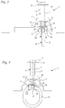
- Fig. 1 shows a load suspension device 1, which is embedded in concrete 2.
- the load suspension device 1 ends flush with a ceiling surface 28 that delimits the space underneath.
- the ceiling surface 28 is in particular the ceiling surface of an elevator shaft.
- the load suspension device 1 has a storage box 3, on which an anchor 6 is fixed.
- the armature 6 protrudes from the storage box 3 in the direction of the side facing away from the ceiling surface 28.
- the storage box 3 has an interior 4, which is closed to the outside by a removable cover 5.
- the cover 5 has latching elements 15 which are latched onto latching projections 25 of the storage box 3. Another detachable one Fixing the lid 5 to the storage box 3 can be advantageous.
- the outside of the cover 5 is flush with the cover surface 28.
- a load-bearing element 11 is arranged in the interior 4 of the storage box 3.
- the load-bearing element 11 is designed as a rigid ring, for example as a chain link.
- the load-bearing element 11 is freely pivotable about a pivot axis 19. If the cover 5 is removed, the load-bearing element 11 pivots downward about the pivot axis 19 in the direction of an arrow 24 until the load-bearing element 11 hangs down approximately vertically.
- 1 and 2 show the load-carrying device 11 in its folded-in position 30. The downwardly pivoted, folded-out position is in the FIGS 3 and 4 shown.
- the load suspension device 11 is pivotally mounted in the embodiment in an eye 23 of an eye screw 7.
- the eyebolt 7 forms both the bearing for the load-bearing element 11 and the fastening means for the armature 6.
- the armature 6 has a spacer sleeve 8, a washer 9 and a nut 10.
- the spacer sleeve 8 extends from the rear of the storage box 3 to the disk 9.
- the eye 23 of the eye screw 7 is arranged in the interior 4 of the storage box 3.
- the eyebolt 7 has a shaft 27 which extends through the wall of the storage box 3 to the outside of the storage box 3. The shaft 27 projects through the spacer sleeve 8 and the disk 9 and is screwed into the nut 10.
- the nut 10 thereby secures the spacer sleeve 8 and the washer 9 on the shaft 27 of the eyebolt 7.
- the spacer sleeve 8 defines the position of the washer 9 on the shaft 27. Because the eyebolt 7 forms both the bearing for the load-bearing element 11 and part of the armature 6, a simple construction with few individual parts is achieved.
- a locking element 12 is provided which, in its unfolded position 31 ( 3 and 4 ) secures.
- the locking element 12 in its unlocked position 18.
- the locking element 12 is movably mounted on a guide element 13 in the direction of a longitudinal central axis 16 of the eye screw 7.
- the longitudinal central axis 16 is advantageously oriented vertically in the installed state.
- the longitudinal central axis 16 preferably coincides with the longitudinal central axis of the armature 6.
- the locking element 12 is mounted on the guide element 13 with a bearing section 21.
- the guide element 13 forms a stop for the locking element 12.
- the guide element 13 has a stop section 26 which interacts with the bearing section 21 of the locking element 12.
- the storage portion 21 to the stop portion 26 a distance a.
- the locking element 12 is acted upon by a spring 14.
- the spring 14 is designed as a compression spring and is supported at one end on the storage box 3 and at the other end on the locking element 12.
- the locking element 12 is provided with four claws 22 in the embodiment.
- the claws 22 are arranged uniformly about the longitudinal central axis 16 and project downwards on both sides of the eye 23.
- two of the four claws 22 are acted upon by the load-bearing element 11.
- the locking element 12 is held in the unlocking position 18, although the locking element 12 is pressed by the spring 14 in the direction of the locking position 17.
- the 3 and 4 show the arrangement with the locking element 12 in its locking position 17 and the load-bearing element 11 in the extended position 31.
- the claws 22 extend on both sides of the pivot axis 19 on the end faces of the load-carrying means 11.
- the sides of the claws 22 facing the load-carrying means 11 form locking contours 20 which are shown in FIGS Projecting pivot path of the load suspension means 11 and thereby pivoting the load suspension element 11 in the in the 1 and 2 prevent unlocking position 18 shown.
- the spring 14 holds the locking element 12 in its locking position 17.
- the bearing section 21 of the locking element 12 lies against the stop section 26 of the guide element 13. As a result, the locking element 12 is secured in its position.
- the eye 23 of the eye screw 7 extends between the claws 22.
- the claws 22 can have recesses in the area of the eye 23. In the locked position 17, the claws 22 extend in pairs on opposite sides of the pivot axis 19. This prevents the load-carrying means 11 from pivoting in both directions.
- the load suspension device 1 is concreted in flush with a ceiling surface 28 in the surrounding concrete.
- the interior 4 of the storage box 3 is closed by the cover 5, and the load-bearing element 11 is in its folded position 30, as in FIGS 1 and 2 shown.
- the cover 5 is removed for the elevator assembly.
- the load-bearing element 11 pivots automatically into its unfolded position 31, specifically because of its weight.
- the locking element 12 is no longer held in its unlocking position 18 by the load-bearing element 11.
- the locking element 12 automatically moves into its locking position 17.
- the spring 14 is provided to assist. If the locking element 12 is of sufficient weight, the spring 14 can also be omitted.
- the locking contours 20 of the claws 22 block pivoting of the load-bearing element 11 about the pivot axis 19.
- an eyelet, a hook or the like can also be easily hooked onto the load-carrying means 11 from a remote location.
- the locking element 12 can be returned to its unlocking position 18 against the force of the spring 14, for example by hand, and then the load-bearing element 11 can be pivoted from the unfolded position 31 into the folded position 30.
- the load-bearing element 11 In the folded-in position 31, the load-bearing element 11 can be secured by the cover 5 or an additional securing means, for example a latch to be fixed to the storage box.
- the locking element 12 is slidably mounted in the vertical direction. In an alternative design, it can also be provided that it can be moved in another direction. If it can be moved in the vertical direction, with the locking element 12 in the locking position 17 being below its position in the unlocking position 18, the locking element 12 can be designed in a simple manner in such a way that the locking element 12 automatically moves into the locking position 17.
- a rigid ring is provided as the load-bearing element 11.
- the load-bearing element 11 is preferably rigid, so that bending of the load-bearing element 11 when hooking in eyes, hooks or the like is prevented.
- the load-bearing element 11 can also be a pivotable cable loop.
Landscapes
- Engineering & Computer Science (AREA)
- Architecture (AREA)
- Civil Engineering (AREA)
- Structural Engineering (AREA)
- Mechanical Engineering (AREA)
- Physics & Mathematics (AREA)
- Electromagnetism (AREA)
- Pivots And Pivotal Connections (AREA)
Abstract
Description
- Die Erfindung betrifft eine Lastaufnahmevorrichtung der im Oberbegriff des Anspruchs 1 angegebenen Gattung.
- Lastaufnahmevorrichtungen zur Einbettung in Beton werden beispielsweise bei der gerüstlosen Aufzugmontage verwendet. Während der Montage des Aufzugs dient der Aufzugskorb als Arbeitsplattform und hängt an einer oder mehreren Lastaufnahmevorrichtungen, die in der Decke des Aufzugsschachts einbetoniert sind.
- Aus der
WO 2013/064497 A1 geht eine Lastaufnahmevorrichtung, nämlich eine Lastschlaufenbox hervor. Als Lastaufnahmeelemente dienen bei derWO 2013/064497 A1 flexible Lastschlaufen. Beim Einhängen eines Ösenhakens an einer solchen Seilschlaufe kann die Seilschlaufe seitlich ausweichen und so das Einhängen erschweren. Ein Ausweichen der Seilschlaufe ist insbesondere zu beobachten, wenn der Ösenhaken eine Federsperre aufweist, die beim Einhängen des Ösenhakens zu überwinden ist, so dass für das Einhängen des Ösenhakens eine vergleichsweise große Kraft auf den Ösenhaken ausgeübt werden muss. - Werden derartige Seilschlaufen mit vergleichsweise großer Steifigkeit ausgebildet, um auch das Einhängen von Ösenhaken mit Federsperre zu erlauben, so ist das Zurückschwenken der Seilschlaufen in den Verwahrkasten nach der Verwendung der Seilschlaufen erschwert.
- Der Erfindung liegt die Aufgabe zugrunde, eine Lastaufnahmevorrichtung der gattungsgemäßen Art zu schaffen, bei der ein Einhängen eines Ösenhakens aus der Ferne auf einfache Weise möglich ist.
- Diese Aufgabe wird durch eine Lastaufnahmevorrichtung mit den Merkmalen des Anspruchs 1 gelöst.
- Erfindungsgemäß ist ein Verriegelungselement vorgesehen, das das mindestens eine Lastaufnahmeelement in der ausgeklappten Stellung gegen ein Verschwenken in die eingeklappte Stellung sichert. Durch das zusätzliche Verriegelungselement kann auf einfache Weise erreicht werden, dass das Lastaufnahmeelement nicht versehentlich zurück in die eingeklappte Stellung verschwenkt wird und Befestigungselemente wie Ösenhaken oder dergleichen auf einfache Weise aus der Ferne an dem Lastaufnahmeelement eingehakt werden können. Das Verriegelungselement kann kleinbauend ausgeführt werden, da lediglich ein Klappen des Lastaufnahmeelements in die eingeklappte Stellung verhindert werden muss. Durch das Verriegelungselement wird dadurch der Bauraum der Lastaufnahmevorrichtung nur unwesentlich beeinflusst. Es wird eine kompakte und einfache Anordnung erreicht, die einfach zu bedienen ist. Nach dem Lösen des Verriegelungselements kann das Lastaufnahmeelement auf einfache Weise zurück in den Verwahrkasten verschwenkt werden.
- Vorteilhaft besitzt das Verriegelungselement eine Verriegelungsstellung, in der das Verriegelungselement das Lastaufnahmeelement sichert und eine Entriegelungsstellung, in der das Lastaufnahmeelement um eine Schwenkachse verschwenkbar ist. Das Lastaufnahmeelement ist dabei vorzugsweise frei schwenkbar. In der Entriegelungsstellung des Verriegelungselements kann das Lastaufnahmeelement dadurch aus der ausgeklappten Stellung einfach und mit geringem Kraftaufwand zurück in die eingeklappte Stellung, also in den Verwahrkasten verschwenkt werden, so dass das Lastaufnahmeelement nach Gebrauch der Lastaufnahmevorrichtung nicht in den Arbeitsraum, insbesondere den Aufzugsschacht ragt und dessen Arbeitshöhe verringert.
- In vorteilhafter Gestaltung ist das Verriegelungselement in Richtung auf seine Verriegelungsstellung gefedert gelagert. Dadurch wird ein sicheres Erreichen der Verriegelungsstellung erreicht, und ein unbeabsichtigtes Verschieben des Verriegelungselements in die Entriegelungsstellung wird verhindert. In alternativer Gestaltung kann jedoch auch vorgesehen sein, dass das Verriegelungselement nicht gefedert gelagert ist. Bevorzugt fällt das Verriegelungselement bei einer Gestaltung ohne Feder aufgrund der Schwerkraft in seine Verriegelungsstellung, wenn das Lastaufnahmeelement in die ausgeklappte Stellung verstellt wird. Dadurch wird eine selbsttätige Verriegelung beim Verstellen des Lastaufnahmeelements in die ausgeklappte Stellung erreicht. Die Verstellung in die ausgeklappte Stellung erfolgt insbesondere dann, wenn ein Deckel des Verwahrkastens abgenommen wird. Bevorzugt fällt das Lastaufnahmeelement beim Abnehmen eines Deckels des Verwahrkastens aufgrund der Schwerkraft in die ausgeklappte Stellung, und das Verriegelungselement fällt mit oder ohne Unterstützung einer Feder in die Verriegelungsstellung.
- Vorteilhaft ist das Verriegelungselement von einer Feder beaufschlagt, die als Druckfeder ausgebildet ist und sich mit einem Ende gegenüber dem Verwahrkasten und mit dem anderen Ende gegenüber dem Verriegelungselement abstützt. Ein einfacher Aufbau ergibt sich, wenn das Verriegelungselement in der eingeklappten Stellung des Lastaufnahmeelements von dem Lastaufnahmeelement in der Entriegelungsstellung gehalten ist. Dadurch kann das Lastaufnahmeelement aus der eingeklappten Stellung selbsttätig in die ausgeklappte Stellung verschwenken, ohne hieran von dem Verriegelungselement gehindert zu werden. Das Verriegelungselement nimmt beim Verstellen des Lastaufnahmeelements in seiner ausgeklappten Stellung die Verriegelungsstellung vorzugsweise selbsttätig ein. Das Einnehmen der Verriegelungsstellung erfolgt dabei vorzugsweise aufgrund der Kraft einer Feder und/oder aufgrund der Gewichtskraft des Verriegelungselements.
- Ein einfacher Aufbau ergibt sich, wenn das Verriegelungselement quer, insbesondere senkrecht zur Schwenkachse des Lastaufnahmeelements verschiebbar gelagert ist. Dadurch kann das Verriegelungselement bei geringem Betätigungsweg eine einfache Verriegelung des Lastaufnahmeelements erreichen. Bevorzugt ist das Verriegelungselement senkrecht oberhalb der Schwenkachse des Lastaufnahmeelements angeordnet und fällt bei der Verstellung in die Verrieglungsstellung aufgrund der Schwerkraft nach unten.
- Ein einfacher Aufbau der Lastaufnahmevorrichtung mit wenigen Einzelteilen ergibt sich, wenn die Lastaufnahmevorrichtung eine Augenschraube aufweist, wobei das Lastaufnahmeelement in einem Auge der Augenschraube schwenkbar gelagert ist. Das Verriegelungselement ist vorteilhaft an einem Schaft der Augenschraube verschiebbar gelagert. Vorteilhaft ist ein Führungselement vorgesehen, mit dem das Verriegelungselement an der Augenschraube gelagert ist. Das Führungselement erlaubt eine gute Führung des Verriegelungselements. Bevorzugt bildet das Führungselement einen Anschlag für die Position des Verriegelungselements in der Verriegelungsstellung. Alternativ kann das Führungselement auch unmittelbar an der Augenschraube gelagert sein.
- Der Verwahrkasten weist vorteilhaft mindestens einen Anker zur Verankerung in dem Beton auf. In bevorzugter Gestaltung ist genau ein Anker vorgesehen. Dadurch kann der Verwahrkasten einfach in eine bestehende Bewehrung für die Betondecke eingepasst werden. Über den Anker wird eine stabile Verankerung im umgebenden Beton erreicht. Ein einfacher Aufbau des Ankers wird erreicht, wenn der Anker eine Scheibe und eine Mutter umfasst. Die Scheibe ist insbesondere an der Augenschraube angeordnet und mit der Mutter gegenüber der Augenschraube gesichert. Die Augenschraube bildet dadurch sowohl ein Funktionselement zur Fixierung des Ankers als auch ein Führungselement für das Verriegelungselement und das Lagerelement für das Lastaufnahmeelement. Dadurch kann ein einfacher Aufbau der Lastaufnahmevorrichtung mit geringer Anzahl von Einzelteilen erreicht werden. In vorteilhafter Gestaltung ist ein Distanzelement vorgesehen, das sich gegenüber dem Verwahrkasten und der Scheibe abstützt und dadurch die Position der Scheibe an der Augenschraube festlegt. Die Augenschraube ist bevorzugt über die Mutter an dem Verwahrkasten fixiert. Dadurch wird ein einfacher Aufbau erreicht. Auch eine andere Gestaltung und Fixierung von Anker und Lagerelementen für das Lastaufnahmeelement kann jedoch vorteilhaft sein.
- Das Lastaufnahmeelement ist bevorzugt starr ausgebildet. Dadurch kann insbesondere aus größerer Entfernung eine Öse oder dergleichen auf einfache Weise an dem Lastaufnahmeelement eingehängt werden. In bevorzugter Gestaltung ist das Lastaufnahmeelement ein starrer Ring, beispielsweise ein Kettenglied. Auch eine andere Gestaltung des Lastaufnahmeelements kann jedoch vorteilhaft sein.
- Ein Ausführungsbeispiel der Erfindung wird im Folgenden anhand der Zeichnung erläutert. Es zeigen:
- Fig. 1 und Fig. 2
- schematische Schnittdarstellungen durch die Lastaufnahmevorrichtung in der eingeklappten Stellung des Lastaufnahmeelements und
- Fig. 3 und Fig. 4
- schematische Schnittdarstellungen der Lastaufnahmevorrichtung in der ausgeklappten Stellung des Lastaufnahmeelements.
-
Fig. 1 zeigt eine Lastaufnahmevorrichtung 1, die in Beton 2 eingebettet ist. Die Lastaufnahmevorrichtung 1 schließt dabei bündig mit einer Deckenfläche 28, die den darunterliegenden Raum begrenzt, ab. Die Deckenfläche 28 ist insbesondere die Deckenfläche eines Aufzugsschachts. Die Lastaufnahmevorrichtung 1 weist einen Verwahrkasten 3 auf, an dem ein Anker 6 festgelegt ist. Der Anker 6 ragt von dem Verwahrkasten 3 in Richtung auf die der Deckenfläche 28 abgewandte Seite. Der Verwahrkasten 3 weist einen Innenraum 4 auf, der nach außen von einem abnehmbaren Deckel 5 verschlossen ist. Im Ausführungsbeispiel weist der Deckel 5 Rastelemente 15 auf, die an Rastvorsprüngen 25 des Verwahrkastens 3 eingerastet sind. Auch eine andere lösbare Fixierung des Deckels 5 am Verwahrkasten 3 kann vorteilhaft sein. Die Außenseite des Deckels 5 schließt im Ausführungsbeispiel bündig mit der Deckenfläche 28 ab. - Im Innenraum 4 des Verwahrkastens 3 ist ein Lastaufnahmeelement 11 angeordnet. Das Lastaufnahmeelement 11 ist im Ausführungsbeispiel als starrer Ring, beispielsweise als Kettenglied ausgeführt. Das Lastaufnahmeelement 11 ist um eine Schwenkachse 19 frei schwenkbar gelagert. Wird der Deckel 5 abgenommen, so verschwenkt das Lastaufnahmeelement 11 um die Schwenkachse 19 in Richtung eines Pfeils 24 nach unten, bis das Lastaufnahmeelement 11 etwa senkrecht nach unten hängt.
Fig. 1 und 2 zeigen das Lastaufnahmemittel 11 in seiner eingeklappten Stellung 30. Die nach unten geschwenkte, ausgeklappte Stellung ist in denFig. 3 und 4 gezeigt. - Wie
Fig. 1 zeigt, ist das Lastaufnahmemittel 11 im Ausführungsbeispiel in einem Auge 23 einer Augenschraube 7 schwenkbar gelagert. Die Augenschraube 7 bildet sowohl das Lager für das Lastaufnahmeelement 11 als auch das Befestigungsmittel für den Anker 6. Der Anker 6 weist im Ausführungsbeispiel eine Distanzhülse 8, eine Scheibe 9 und eine Mutter 10 auf. Die Distanzhülse 8 erstreckt sich von der Rückseite des Verwahrkastens 3 bis zu der Scheibe 9. Das Auge 23 der Augenschraube 7 ist im Innenraum 4 des Verwahrkastens 3 angeordnet. Die Augenschraube 7 besitzt einen Schaft 27, der sich durch die Wand des Verwahrkastens 3 auf die Außenseite des Verwahrkastens 3 erstreckt. Der Schaft 27 ragt durch die Distanzhülse 8 und die Scheibe 9 und ist in die Mutter 10 eingeschraubt. Die Mutter 10 sichert dadurch die Distanzhülse 8 und die Scheibe 9 auf dem Schaft 27 der Augenschraube 7. Die Distanzhülse 8 legt die Position der Scheibe 9 auf dem Schaft 27 fest. Dadurch, dass die Augenschraube 7 sowohl die Lagerung für das Lastaufnahmeelement 11 als auch einen Teil des Ankers 6 bildet, wird ein einfacher Aufbau mit wenigen Einzelteilen erreicht. - Erfindungsgemäß ist ein Verriegelungselement 12 vorgesehen, das das Lastaufnahmeelement 11 in seiner ausgeklappten Stellung 31 (
Fig. 3 und 4 ) sichert. In denFig. 1 und 2 befindet sich das Verriegelungselement 12 in seiner Entriegelungsstellung 18. Im Ausführungsbeispiel ist das Verriegelungselement 12 an einem Führungselement 13 in Richtung einer Längsmittelachse 16 der Augenschraube 7 beweglich gelagert. Die Längsmittelachse 16 ist vorteilhaft im Einbauzustand senkrecht ausgerichtet. Die Längsmittelachse 16 fällt vorzugsweise mit der Längsmittelachse des Ankers 6 zusammen. Das Verriegelungselement 12 ist mit einem Lagerungsabschnitt 21 an dem Führungselement 13 gelagert. Im Ausführungsbeispiel bildet das Führungselement 13 einen Anschlag für das Verriegelungselement 12. Hierzu weist das Führungselement 13 einen Anschlagabschnitt 26 auf, der mit dem Lagerungsabschnitt 21 des Verriegelungselements 12 zusammenwirkt. In der inFig. 1 gezeigten Entriegelungsstellung 18 weist der Lagerungsabschnitt 21 zu dem Anschlagabschnitt 26 einen Abstand a auf. - Wie
Fig. 1 auch zeigt, ist das Verriegelungselement 12 von einer Feder 14 beaufschlagt. Die Feder 14 ist im Ausführungsbeispiel als Druckfeder ausgebildet und stützt sich mit einem Ende am Verwahrkasten 3 und mit dem anderen Ende am Verriegelungselement 12 ab. - Wie die
Fig. 1 und 2 zeigen, ist das Verriegelungselement 12 im Ausführungsbeispiel mit vier Klauen 22 versehen. Die Klauen 22 sind im Ausführungsbeispiel gleichmäßig um die Längsmittelachse 16 angeordnet und ragen beidseitig des Auges 23 nach unten. In der eingeklappten Stellung 30 des Lastaufnahmeelements 11 werden zwei der vier Klauen 22 von dem Lastaufnahmeelement 11 beaufschlagt. Dadurch wird das Verriegelungselement 12 in der Entriegelungsstellung 18 gehalten, obwohl das Verriegelungselement 12 von der Feder 14 in Richtung auf die Verriegelungsstellung 17 gedrückt wird. - Die
Fig. 3 und 4 zeigen die Anordnung mit dem Verriegelungselement 12 in seiner Verriegelungsstellung 17 und dem Lastaufnahmeelement 11 in der ausgeklappten Stellung 31. Wie dieFig. 3 und 4 zeigen, erstrecken sich die Klauen 22 beidseitig der Schwenkachse 19 an den Stirnseiten des Lastaufnahmemittels 11. Die dem Lastaufnahmemittel 11 zugewandten Seiten der Klauen 22 bilden Verriegelungskonturen 20, die in den Verschwenkweg des Lastaufnahmemittels 11 ragen und dadurch ein Verschwenken des Lastaufnahmeelements 11 in die in denFig. 1 und 2 gezeigte Entriegelungsstellung 18 verhindern. Die Feder 14 hält das Verriegelungselement 12 in seiner Verriegelungsstellung 17. Der Lagerungsabschnitt 21 des Verriegelungselements 12 liegt am Anschlagabschnitt 26 des Führungselements 13 an. Dadurch ist das Verriegelungselement 12 in seiner Position gesichert. - Wie
Fig. 4 zeigt, erstreckt sich das Auge 23 der Augenschraube 7 zwischen den Klauen 22. Die Klauen 22 können im Bereich des Auges 23 dabei Aussparungen aufweisen. In der Verriegelungsstellung 17 erstrecken sich die Klauen 22 paarweise auf gegenüberliegenden Seiten der Schwenkachse 19. Dadurch ist ein Verschwenken des Lastaufnahmemittels 11 in beide Richtungen verhindert. - Die Lastaufnahmevorrichtung 1 wird bündig mit einer Deckenfläche 28 im umgebenden Beton einbetoniert. Dabei ist der Innenraum 4 des Verwahrkastens 3 von dem Deckel 5 verschlossen, und das Lastaufnahmeelement 11 befindet sich in seiner eingeklappten Stellung 30, wie in den
Fig. 1 und 2 gezeigt. Zur Aufzugmontage wird der Deckel 5 entfernt. Dadurch verschwenkt das Lastaufnahmeelement 11 selbsttätig in seine ausgeklappte Stellung 31, und zwar aufgrund seiner Gewichtskraft. In der ausgeklappten Stellung 31 ist das Verriegelungselement 12 nicht mehr vom Lastaufnahmeelement 11 in seiner Entriegelungsstellung 18 gehalten. Dadurch verstellt sich das Verriegelungselement 12 selbsttätig in seine Verriegelungsstellung 17. Im Ausführungsbeispiel ist unterstützend die Feder 14 vorgesehen. Bei ausreichendem Gewicht des Verriegelungselements 12 kann die Feder 14 auch entfallen. In der Verriegelungsstellung 17 des Verriegelungselements 12 blockieren die Verriegelungskonturen 20 der Klauen 22 ein Verschwenken des Lastaufnahmeelements 11 um die Schwenkachse 19. Dadurch kann in dieser Position eine Öse, ein Haken oder dergleichen bequem auch von einem entfernt liegenden Ort an dem Lastaufnahmemittel 11 eingehakt werden. Nach Beendigung der Arbeiten kann das Verriegelungselement 12 entgegen der Kraft der Feder 14 in seine Entriegelungsstellung 18 zurückgestellt werden, beispielsweise von Hand, und anschließend das Lastaufnahmeelement 11 aus der ausgeklappten Stellung 31 in die eingeklappte Stellung 30 verschwenkt werden. In der eingeklappten Stellung 31 kann das Lastaufnahmeelement 11 durch den Deckel 5 oder ein zusätzliches Sicherungsmittel, beispielsweise einen am Verwahrkasten zu fixierenden Riegel, gesichert werden. - Im Ausführungsbeispiel ist das Verriegelungselement 12 in senkrechter Richtung verschiebbar gelagert. In alternativer Gestaltung kann auch eine Verschiebbarkeit in eine andere Richtung vorgesehen sein. Bei einer Verschiebbarkeit in senkrechter Richtung, wobei das Verriegelungselement 12 in Verriegelungsstellung 17 unterhalb seiner Position in Entriegelungsstellung 18 liegt, kann das Verriegelungselement 12 auf einfache Weise so gestaltet werden, dass das Verriegelungselement 12 selbsttätig in die Verriegelungsstellung 17 gelangt.
- Im Ausführungsbeispiel ist als Lastaufnahmeelement 11 ein starrer Ring vorgesehen. Auch eine andere Gestaltung des Lastaufnahmeelements 11 kann jedoch vorteilhaft sein. Das Lastaufnahmeelement 11 ist bevorzugt starr ausgebildet, so dass ein Verbiegen des Lastaufnahmeelements 11 beim Einhängen von Ösen, Haken oder dergleichen verhindert ist. In alternativer Gestaltung kann das Lastaufnahmeelement 11 jedoch auch eine schwenkbar gelagerte Seilschlaufe sein.
Claims (15)
- Lastaufnahmevorrichtung umfassend einen Verwahrkasten (3) zur Einbettung in Beton (2) und mindestens ein Lastaufnahmeelement (11), wobei das Lastaufnahmeelement (11) zwischen einer eingeklappten Stellung (30) und einer ausgeklappten Stellung (31) verschwenkbar ist, wobei das Lastaufnahmeelement (11) in der eingeklappten Stellung (30) in einem Innenraum (4) des Verwahrkastens (3) angeordnet ist und in der ausgeklappten Stellung (31) mindestens teilweise aus dem Innenraum (4) ragt,
dadurch gekennzeichnet, dass ein Verriegelungselement (12) vorgesehen ist, das das mindestens eine Lastaufnahmeelement (11) in der ausgeklappten Stellung (31) gegen eine Verschwenkung in die eingeklappte Stellung (30) sichert. - Lastaufnahmevorrichtung nach Anspruch 1,
dadurch gekennzeichnet, dass das Verriegelungselement (12) eine Verriegelungsstellung (17), in der das Verriegelungselement (12) das Lastaufnahmeelement (11) sichert, und eine Entriegelungsstellung (18), in der das Lastaufnahmeelement (11) um eine Schwenkachse (19) verschwenkbar ist, aufweist, - Lastaufnahmevorrichtung nach Anspruch 2,
dadurch gekennzeichnet, dass das Verriegelungselement (12) in Richtung auf seine Verriegelungsstellung (17) gefedert gelagert ist. - Lastaufnahmevorrichtung nach Anspruch 3,
dadurch gekennzeichnet, dass das Verriegelungselement (12) von einer Feder (14) beaufschlagt ist, die als Druckfeder ausgebildet ist und sich mit einem Ende gegenüber dem Verwahrkasten (3) und mit dem anderen Ende gegenüber dem Verriegelungselement (12) abstützt. - Lastaufnahmevorrichtung nach einem der Ansprüche 2 bis 4,
dadurch gekennzeichnet, dass das Verriegelungselement (12) in der eingeklappten Stellung (30) des Lastaufnahmeelements (11) von dem Lastaufnahmeelement (11) in der Entriegelungsstellung (18) gehalten ist. - Lastaufnahmevorrichtung nach einem der Ansprüche 2 bis 5,
dadurch gekennzeichnet, dass das Verriegelungselement (12) beim Verstellen des Lastaufnahmeelements (11) in seine ausgeklappte Stellung (31) selbsttätig die Verriegelungsstellung (17) einnimmt. - Lastaufnahmevorrichtung nach einem der Ansprüche 2 bis 6,
dadurch gekennzeichnet, dass das Verriegelungselement (12) quer, insbesondere senkrecht zur Schwenkachse (19) des Lastaufnahmeelements (11) verschiebbar gelagert ist. - Lastaufnahmevorrichtung nach einem der Ansprüche 1 bis 7,
dadurch gekennzeichnet, dass die Lastaufnahmevorrichtung (1) eine Augenschraube (7) aufweist, wobei das Lastaufnahmeelement (11) in einem Auge (23) der Augenschraube (7) schwenkbar gelagert ist. - Lastaufnahmevorrichtung nach Anspruch 8,
dadurch gekennzeichnet, dass das Verriegelungselement (12) an einem Schaft (17) der Augenschraube (7) verschiebbar gelagert ist. - Lastaufnahmevorrichtung nach Anspruch 9,
dadurch gekennzeichnet, dass ein Führungselement (13) vorgesehen ist, mit dem das Verriegelungselement (12) an der Augenschraube (7) gelagert ist. - Lastaufnahmevorrichtung nach Anspruch 10,
dadurch gekennzeichnet, dass das Führungselement (13) einen Anschlag für die Position des Verriegelungselements (12) in der Verriegelungsstellung (17) bildet. - Lastaufnahmevorrichtung nach einem der Ansprüche 1 bis 11,
dadurch gekennzeichnet, dass der Verwahrkasten (3) mindestens einen Anker (6) zur Verankerung in dem Beton (2) aufweist. - Lastaufnahmevorrichtung nach Anspruch 12,
dadurch gekennzeichnet, dass der Anker (6) eine Scheibe (9) und eine Mutter (10) umfasst, wobei die Scheibe (9) insbesondere an der Augenschraube (7) angeordnet und mit der Mutter (10) gegenüber der Augenschraube (7) gesichert ist. - Lastaufnahmevorrichtung nach Anspruch 13,
dadurch gekennzeichnet, dass die Augenschraube (7) über die Mutter (10) an dem Verwahrkasten (3) fixiert ist. - Lastaufnahmevorrichtung nach einem der Ansprüche 1 bis 14,
dadurch gekennzeichnet, dass das Lastaufnahmeelement (11) starr ausgebildet ist, wobei das Lastaufnahmeelement (11) insbesondere ein starrer Ring ist.
Priority Applications (1)
| Application Number | Priority Date | Filing Date | Title |
|---|---|---|---|
| EP18201701.2A EP3643854B1 (de) | 2018-10-22 | 2018-10-22 | Lastaufnahmevorrichtung |
Applications Claiming Priority (1)
| Application Number | Priority Date | Filing Date | Title |
|---|---|---|---|
| EP18201701.2A EP3643854B1 (de) | 2018-10-22 | 2018-10-22 | Lastaufnahmevorrichtung |
Publications (3)
| Publication Number | Publication Date |
|---|---|
| EP3643854A1 true EP3643854A1 (de) | 2020-04-29 |
| EP3643854B1 EP3643854B1 (de) | 2025-12-03 |
| EP3643854C0 EP3643854C0 (de) | 2025-12-03 |
Family
ID=63965222
Family Applications (1)
| Application Number | Title | Priority Date | Filing Date |
|---|---|---|---|
| EP18201701.2A Active EP3643854B1 (de) | 2018-10-22 | 2018-10-22 | Lastaufnahmevorrichtung |
Country Status (1)
| Country | Link |
|---|---|
| EP (1) | EP3643854B1 (de) |
Cited By (5)
| Publication number | Priority date | Publication date | Assignee | Title |
|---|---|---|---|---|
| DE202023000980U1 (de) | 2023-05-04 | 2023-07-04 | PohlCon GmbH | Lastaufnahmevorrichtung, insbesondere für den Aufzugsbau |
| EP4442918A1 (de) * | 2023-04-05 | 2024-10-09 | Wüest Gebäudetechnik GmbH | Befestigungsvorrichtung zum verbinden eines objekts mit einer struktur und verwendung einer solchen befestigungsvorrichtung |
| DE102023001801A1 (de) | 2023-05-04 | 2024-11-07 | PohlCon GmbH | Lastaufnahmevorrichtung, insbesondere für den Aufzugsbau |
| EP4461691A1 (de) | 2023-05-04 | 2024-11-13 | PohlCon GmbH | Lastaufnahmevorrichtung, insbesondere für den aufzugsbau |
| EP4464640A1 (de) | 2023-05-19 | 2024-11-20 | PohlCon AG (Schweiz) | Lastaufnahmevorrichtung, insbesondere für den aufzugsbau |
Citations (6)
| Publication number | Priority date | Publication date | Assignee | Title |
|---|---|---|---|---|
| DE330106C (de) * | 1920-03-09 | 1920-12-07 | Hermann Dieck | Vorrichtung zum Befestigen von besonders nur voruebergehend zur Aufstellung kommenden Maschinen |
| CH508820A (de) * | 1968-07-11 | 1971-06-15 | Waerner Thor | Montageanker |
| WO1987000823A1 (en) * | 1985-08-07 | 1987-02-12 | Richmond Screw Anchor Co. | Hoist coupling |
| WO2001042601A1 (en) * | 1999-12-10 | 2001-06-14 | Southco, Inc. | Pull with pivoting tie-down hoop |
| US7651305B1 (en) * | 2009-06-10 | 2010-01-26 | The United States Of America As Represented By The Secretary Of The Navy | Retractable fitting |
| WO2013064497A1 (de) | 2011-10-31 | 2013-05-10 | Inventio Ag | Lastschlaufenbox und ankerungsvorrichtung |
-
2018
- 2018-10-22 EP EP18201701.2A patent/EP3643854B1/de active Active
Patent Citations (6)
| Publication number | Priority date | Publication date | Assignee | Title |
|---|---|---|---|---|
| DE330106C (de) * | 1920-03-09 | 1920-12-07 | Hermann Dieck | Vorrichtung zum Befestigen von besonders nur voruebergehend zur Aufstellung kommenden Maschinen |
| CH508820A (de) * | 1968-07-11 | 1971-06-15 | Waerner Thor | Montageanker |
| WO1987000823A1 (en) * | 1985-08-07 | 1987-02-12 | Richmond Screw Anchor Co. | Hoist coupling |
| WO2001042601A1 (en) * | 1999-12-10 | 2001-06-14 | Southco, Inc. | Pull with pivoting tie-down hoop |
| US7651305B1 (en) * | 2009-06-10 | 2010-01-26 | The United States Of America As Represented By The Secretary Of The Navy | Retractable fitting |
| WO2013064497A1 (de) | 2011-10-31 | 2013-05-10 | Inventio Ag | Lastschlaufenbox und ankerungsvorrichtung |
Cited By (5)
| Publication number | Priority date | Publication date | Assignee | Title |
|---|---|---|---|---|
| EP4442918A1 (de) * | 2023-04-05 | 2024-10-09 | Wüest Gebäudetechnik GmbH | Befestigungsvorrichtung zum verbinden eines objekts mit einer struktur und verwendung einer solchen befestigungsvorrichtung |
| DE202023000980U1 (de) | 2023-05-04 | 2023-07-04 | PohlCon GmbH | Lastaufnahmevorrichtung, insbesondere für den Aufzugsbau |
| DE102023001801A1 (de) | 2023-05-04 | 2024-11-07 | PohlCon GmbH | Lastaufnahmevorrichtung, insbesondere für den Aufzugsbau |
| EP4461691A1 (de) | 2023-05-04 | 2024-11-13 | PohlCon GmbH | Lastaufnahmevorrichtung, insbesondere für den aufzugsbau |
| EP4464640A1 (de) | 2023-05-19 | 2024-11-20 | PohlCon AG (Schweiz) | Lastaufnahmevorrichtung, insbesondere für den aufzugsbau |
Also Published As
| Publication number | Publication date |
|---|---|
| EP3643854B1 (de) | 2025-12-03 |
| EP3643854C0 (de) | 2025-12-03 |
Similar Documents
| Publication | Publication Date | Title |
|---|---|---|
| EP3643854A1 (de) | Lastaufnahmevorrichtung | |
| DE102018103897A1 (de) | Gerüst mit einer Aushebesicherungsvorrichtung und Verfahren zur Sicherung eines Gerüstbodens gegen Ausheben | |
| DE202020104196U1 (de) | Baugerüst | |
| DE68909281T2 (de) | Verstellbare Säule für ein Lastkraftfahrzeug mit verschiebbarer Abdeckung. | |
| EP1902185B2 (de) | Kletterschalung mit angelenktem kletterschuh | |
| DE202015003671U1 (de) | Mast | |
| DE102009018689B4 (de) | Auslegerelement für ein Hebezeug | |
| DE202020103146U1 (de) | Vorrichtung zur Anbringung von Absturzsicherungen an Baugerüsten | |
| DE212022000073U1 (de) | Markise für Fahrzeug | |
| DE102016106533A1 (de) | Sicherungssäule | |
| EP3630665B1 (de) | Zusatzplattform zu einer arbeitsplattform | |
| EP2773824B1 (de) | Lastschlaufenbox und ankerungsvorrichtung | |
| DE3149690A1 (de) | Vorrichtung zum umscheren des hubseils bei kranen | |
| DE202022101674U1 (de) | Vorrichtung mit einem Sicherheitsgurt-Aufhängepunkt für den Betrieb in großer Höhe | |
| DE29906047U1 (de) | Auffanggerät | |
| DE112021002851T5 (de) | Sicherheitsleiter | |
| DE102013004820A1 (de) | Halterungsvorrichtung zum Lagern von Haltestangen an einem Kran | |
| DE202018006826U1 (de) | Lastaufnahmevorrichtung | |
| DE102019204713A1 (de) | Schalungssystem für die Herstellung von Betonwänden | |
| DE2260465C3 (de) | Zerlegbare Stange | |
| EP4132874B1 (de) | Transporthaken | |
| DE102004039470A1 (de) | Betonschalungsschloss und Betonschalelement | |
| DE4114338A1 (de) | Anordnung zum einhaengen einer arbeitsbuehne | |
| DE2305425A1 (de) | Vorrichtung zum errichten von kranmasten | |
| DE102022130489A1 (de) | Arbeitsbühne |
Legal Events
| Date | Code | Title | Description |
|---|---|---|---|
| PUAI | Public reference made under article 153(3) epc to a published international application that has entered the european phase |
Free format text: ORIGINAL CODE: 0009012 |
|
| STAA | Information on the status of an ep patent application or granted ep patent |
Free format text: STATUS: THE APPLICATION HAS BEEN PUBLISHED |
|
| AK | Designated contracting states |
Kind code of ref document: A1 Designated state(s): AL AT BE BG CH CY CZ DE DK EE ES FI FR GB GR HR HU IE IS IT LI LT LU LV MC MK MT NL NO PL PT RO RS SE SI SK SM TR |
|
| AX | Request for extension of the european patent |
Extension state: BA ME |
|
| STAA | Information on the status of an ep patent application or granted ep patent |
Free format text: STATUS: REQUEST FOR EXAMINATION WAS MADE |
|
| 17P | Request for examination filed |
Effective date: 20201016 |
|
| RBV | Designated contracting states (corrected) |
Designated state(s): AL AT BE BG CH CY CZ DE DK EE ES FI FR GB GR HR HU IE IS IT LI LT LU LV MC MK MT NL NO PL PT RO RS SE SI SK SM TR |
|
| STAA | Information on the status of an ep patent application or granted ep patent |
Free format text: STATUS: EXAMINATION IS IN PROGRESS |
|
| 17Q | First examination report despatched |
Effective date: 20210901 |
|
| RAP3 | Party data changed (applicant data changed or rights of an application transferred) |
Owner name: LEVIAT GMBH |
|
| GRAP | Despatch of communication of intention to grant a patent |
Free format text: ORIGINAL CODE: EPIDOSNIGR1 |
|
| STAA | Information on the status of an ep patent application or granted ep patent |
Free format text: STATUS: GRANT OF PATENT IS INTENDED |
|
| INTG | Intention to grant announced |
Effective date: 20250722 |
|
| GRAS | Grant fee paid |
Free format text: ORIGINAL CODE: EPIDOSNIGR3 |
|
| GRAA | (expected) grant |
Free format text: ORIGINAL CODE: 0009210 |
|
| STAA | Information on the status of an ep patent application or granted ep patent |
Free format text: STATUS: THE PATENT HAS BEEN GRANTED |
|
| AK | Designated contracting states |
Kind code of ref document: B1 Designated state(s): AL AT BE BG CH CY CZ DE DK EE ES FI FR GB GR HR HU IE IS IT LI LT LU LV MC MK MT NL NO PL PT RO RS SE SI SK SM TR |
|
| REG | Reference to a national code |
Ref country code: CH Ref legal event code: F10 Free format text: ST27 STATUS EVENT CODE: U-0-0-F10-F00 (AS PROVIDED BY THE NATIONAL OFFICE) Effective date: 20251203 Ref country code: GB Ref legal event code: FG4D Free format text: NOT ENGLISH |
|
| REG | Reference to a national code |
Ref country code: CH Ref legal event code: R17 Free format text: ST27 STATUS EVENT CODE: U-0-0-R10-R17 (AS PROVIDED BY THE NATIONAL OFFICE) Effective date: 20251205 |
|
| REG | Reference to a national code |
Ref country code: IE Ref legal event code: FG4D Free format text: LANGUAGE OF EP DOCUMENT: GERMAN |
|
| U01 | Request for unitary effect filed |
Effective date: 20251203 |
|
| U07 | Unitary effect registered |
Designated state(s): AT BE BG DE DK EE FI FR IT LT LU LV MT NL PT RO SE SI Effective date: 20251209 |
|
| PG25 | Lapsed in a contracting state [announced via postgrant information from national office to epo] |
Ref country code: ES Free format text: LAPSE BECAUSE OF FAILURE TO SUBMIT A TRANSLATION OF THE DESCRIPTION OR TO PAY THE FEE WITHIN THE PRESCRIBED TIME-LIMIT Effective date: 20251203 |
|
| PG25 | Lapsed in a contracting state [announced via postgrant information from national office to epo] |
Ref country code: NO Free format text: LAPSE BECAUSE OF FAILURE TO SUBMIT A TRANSLATION OF THE DESCRIPTION OR TO PAY THE FEE WITHIN THE PRESCRIBED TIME-LIMIT Effective date: 20260303 |
|
| PG25 | Lapsed in a contracting state [announced via postgrant information from national office to epo] |
Ref country code: HR Free format text: LAPSE BECAUSE OF FAILURE TO SUBMIT A TRANSLATION OF THE DESCRIPTION OR TO PAY THE FEE WITHIN THE PRESCRIBED TIME-LIMIT Effective date: 20251203 |
|
| PG25 | Lapsed in a contracting state [announced via postgrant information from national office to epo] |
Ref country code: RS Free format text: LAPSE BECAUSE OF FAILURE TO SUBMIT A TRANSLATION OF THE DESCRIPTION OR TO PAY THE FEE WITHIN THE PRESCRIBED TIME-LIMIT Effective date: 20260303 |
|
| PG25 | Lapsed in a contracting state [announced via postgrant information from national office to epo] |
Ref country code: PL Free format text: LAPSE BECAUSE OF FAILURE TO SUBMIT A TRANSLATION OF THE DESCRIPTION OR TO PAY THE FEE WITHIN THE PRESCRIBED TIME-LIMIT Effective date: 20251203 |