EP3642910B1 - Erdungskontakt - Google Patents
Erdungskontakt Download PDFInfo
- Publication number
- EP3642910B1 EP3642910B1 EP18722385.4A EP18722385A EP3642910B1 EP 3642910 B1 EP3642910 B1 EP 3642910B1 EP 18722385 A EP18722385 A EP 18722385A EP 3642910 B1 EP3642910 B1 EP 3642910B1
- Authority
- EP
- European Patent Office
- Prior art keywords
- brush
- brush shaft
- base plate
- shaft
- holder
- Prior art date
- Legal status (The legal status is an assumption and is not a legal conclusion. Google has not performed a legal analysis and makes no representation as to the accuracy of the status listed.)
- Active
Links
Images



Classifications
-
- H—ELECTRICITY
- H01—ELECTRIC ELEMENTS
- H01R—ELECTRICALLY-CONDUCTIVE CONNECTIONS; STRUCTURAL ASSOCIATIONS OF A PLURALITY OF MUTUALLY-INSULATED ELECTRICAL CONNECTING ELEMENTS; COUPLING DEVICES; CURRENT COLLECTORS
- H01R39/00—Rotary current collectors, distributors or interrupters
- H01R39/02—Details for dynamo electric machines
- H01R39/38—Brush holders
- H01R39/39—Brush holders wherein the brush is fixedly mounted in the holder
Definitions
- the invention relates to a grounding contact for the controlled steering of electrical current according to the features of patent claim 1.
- a grounding contact represents a low-resistance bridge that protects the critical points of a component from damage caused by high currents.
- grounding contacts conduct electricity around critical points such as wheel bearings.
- a holding device for brushes which forms a reverse current and/or grounding contact between parts moving relative to one another on rail vehicles.
- the holding device has at least one metallic brush shaft, in which a brush is displaceably arranged, and at least one pressure device which is held in a recess on the brush shaft and exerts a force on one end of the brush.
- the brush shaft merges into a base plate in one piece.
- the base plate with the brush shaft is a cast component.
- the brush shafts are attached to load-bearing components using a grub screw or a union nut.
- a grub screw or a union nut The insertion of brush holders into pocket-like recesses in a cylindrical housing is known from the prior art, with the brush holders being held in position by a cover.
- Brush holders can be made in one piece from plastic by injection molding or can also be connected to a housing via purely non-positive screw connections.
- the invention is based on the object of providing a grounding contact with a compact and robust brush holder that is inexpensive and easy to produce and suitable for standardization.
- the invention relates to a grounding contact for the controlled control of electrical current. It includes a brush holder with a base plate and with at least one brush shaft for holding a brush. The at least one brush shaft is positively connected to the base plate.
- the advantage of the grounding contact according to the invention is the modular design with regard to the brush shaft.
- the base plate and the brush shaft can be manufactured separately using laser and water jet cutting processes. Model and tool costs for the mold in the casting process are eliminated. Processing with a laser and water jet process leads to a lower metal removal volume. The entire brush shaft no longer needs to be cleared by machining.
- the modular construction principle of the brush holder allows the flexibility of the manufacturing process to be improved and production times to be reduced. According to the invention, the modular construction principle of the brush holder makes it possible to standardize the brush shaft regardless of the design of the base plate and to produce it as a mass product.
- the invention provides for the brush shaft to be designed as a standard component for the current brushes with dimensions of 40 x 20 mm or 32 x 12.5 mm. Standardized brush shafts with other dimensions can also be used in the invention.
- the brushes are preferably metal-graphite brushes, also known as carbon brushes. However, the brushes can also be made of other metals or metal alloys with high electrical conductivity and contain, for example, copper, silver or molybdenum.
- the grounding contact has contact means in the form of strands that can be connected to the base plate and conduct the electrical current to the brush.
- the strands are flexible and allow the brushes to be tracked under the influence of a spring force.
- the connection between the base plate and the strands is made via tubular cable lugs on the strands, which can be screwed to the base plate in an electrically conductive manner.
- the base plate has at least one brush shaft receptacle to accommodate the at least one brush shaft.
- the form-fitting connection between the base plate and the brush shaft makes installation easy and, if necessary, easy to replace the brush shaft, e.g if the brush shaft is damaged or worn.
- the positive connection is detachable.
- the supporting base plate is preferably a flat plate made of an electrically conductive material, in particular metal.
- the brush shaft has clamping tongues, via which the brush shaft is clamped to the base plate.
- the clamping tongues have hooks at their free ends, which reach behind an edge of the brush shaft holder in the base plate.
- the clamping tongues are preferably arranged on at least three sides of the brush shaft. Since the brushes are essentially rectangular, the brush shaft also has a substantially rectangular cross section. A diametrical arrangement of clamping tongues is ideal. An arrangement of three clamping tongues also enables the brush shaft to be adequately fixed.
- a positive connection with clamping tongues has the advantage that a connection between the base plate and the brush shaft is possible without additional fasteners, such as screws, pins or rivets, thereby eliminating the need for tools. This makes assembly easier.
- the clamping force of the clamping tongues is chosen to be so large that they do not have to be secured against springing back using additional securing devices.
- the brush shaft has a support surface for support on the base plate on the underside.
- the support surface is preferably located adjacent to the fixed ends of the clamping tongues. As a result, the brush shaft is held clamped in a perpendicular direction to the base plate.
- the brush shaft completely penetrates the brush shaft holder.
- the clamping tongues or hooks protrude beyond the base plate. Through a combination of positive and clamping connections, the brush shaft is securely fixed and correct guidance of the brush is ensured.
- the base plate can have a corresponding number of brush shaft holders for several brushes. This allows larger currents to be transmitted. Operational safety is also increased.
- the base plate preferably has three brush shaft receptacles.
- the individual brush shafts can preferably be manufactured separately. It is also possible to manufacture several brush shafts as a common component, which is then connected to the base plate.
- a spring element In order to exert a spring force on the brush in the brush shaft in the longitudinal direction of the brush shaft, a spring element is provided, which is preferably designed as a roller band spring.
- the spring element has the task of exerting a spring force on the brush, so that the brush is constantly in contact with a grinding wheel for power transmission.
- the spring element is preferably fastened in the brush shaft.
- a spring holder is mounted in the brush shaft so that the holding force for the spring element is absorbed by the brush shaft itself. No forces are introduced into the base plate.
- the brush shaft including the spring holder and the spring element form an independent assembly that is intended for coupling to the base plate.
- the brush shaft can be electrically conductive.
- the brushes are connected to the base plate via the strands to carry current.
- the brush shaft can therefore consist of electrically non-conductive material, in particular a plastic. This has the advantage that the entire grounding contact is lighter and also cheaper to manufacture.
- the brush shaft can be produced inexpensively, particularly as an injection molded component. Another advantage is the good sliding properties of some plastics, which in turn is optimal for guiding the brush within the brush shaft.
- the grounding contact preferably has a cover that protects the brush with electrical connections, contacts and strands.
- the cover can be fastened to the base plate in a force-fitting and/or positive manner, for example using screws.
- the Figures 1 and 2 show a brush holder 2, as is known from the prior art.
- the brush holder 2 has a base plate 3 and a brush shaft 4.
- the base plate 3 and the brush shaft 4 are made in one piece and made of the same material.
- the brush shaft 4 shown is used to hold a brush, not shown.
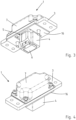
- the Figures 3 and 4 each show perspective views of a grounding contact 1 according to the invention.
- the grounding contact 1 has a base plate 3, a brush shaft 4 and a brush 6.
- the base plate 3 and the brush shaft 4 are not designed in one piece according to the invention.
- the base plate 3 has a brush shaft receptacle 5 into which the brush shaft 4 is inserted.
- the outer contour of the brush shaft 4 corresponds to the contour of the brush shaft holder 5 in the base plate 3, so that a precise fit of the brush shaft 4 within the brush shaft holder 5 of the base plate 3 is guaranteed.
- An area above the base plate 3 is protected by a cover 7, which is attached to the base plate 3 by means of screws.
- Figure 3 shows that one end of the brush 6 protrudes from the brush shaft 4. This one end of the brush 6 is in contact with a component (not shown) (slip ring) in order to dissipate electrical current via this component.
- Figure 6 shows on an underside of the base plate 3 an electrically insulating lower plate 16 with a centrally arranged recess for the brush shaft 4.
- Figure 5 shows the ground contact 1 according to the invention Figures 3 and 4 in a top view without cover 7.
- the base plate 3 has a rectangular shape.
- the brush shaft holder 5 for receiving the brush shaft 4 is arranged in the middle of the base plate 3.
- the brush 6 is arranged in the brush shaft 4.
- Electrical contact means 8 in the form of flexible strands are connected to the base plate 3 of the grounding contact 1 via two connections 9 and establish the current-conducting connection between the base plate 3 and the brush 6.
- the brush 6 has two contact means 8 (strands), with the cable lugs 9 being fastened to the base plate 3 with screws.
- the cable lugs 9 being fastened to the base plate 3 with screws.
- At the opposite ends of the base plate 3 there are receptacles for tubular cable lugs 10, which are also attached to the base plate 3 by means of screws. The electrical current is fed to the base plate 3 for further transmission via supply lines (not shown) via the screwed-on tubular cable lugs 10.
- Figure 6 makes a cut along line AA according to Figure 5 represents.
- the ground contact 1 is closed with a cover 7, the cover 7 covering the contact means 8, the brush 6 and a large area of the base plate 3.
- the brush shaft 4 completely penetrates the brush shaft receptacle 5.
- the brush shaft 4 is clamped to the base plate 3 by means of clamping tongues 11 ( Figures 6 and 7 ). At their free ends 12, the clamping tongues 11 have hooks 17 which grip on an upper side of the base plate 3.
- the top of the base plate 3 is the side on which the lid 7 is attached.
- the underside of the base plate 3 is the side of the base plate 3 opposite the top.
- the terms top and bottom or top and bottom are not restrictive for the installation position of the grounding contact 1.
- the brush shaft 4 has a support surface 13 to support the base plate 3 on the underside. It essentially consists of a projection or a recess in the brush shaft 4, which, together with the hook 17 of the clamping tongue 11, represents a positive connection for receiving the base plate 3 ( Figure 7 ).
- FIG. 7 shows a further sectional view of the ground contact 1 according to Figure 5 with lid 7.
- Figure 7 shows a spring holder 14 for receiving a spring element 15.
- the spring holder 14 is positively connected to the brush shaft 4.
- the spring holder 14, together with the spring element 15 and the brush shaft 4, passes through the brush shaft receptacle 5.
- the spring element 15 is a roller band spring that presses on the brush 6 from the top.
- one end of the brush 6 rests on a rotating component, not shown, so that the brush 6 wears out.
- the brush 6 is slidably mounted in the brush shaft 4, with the force exerted by the spring element pressing the brush 6 against the rotating component.
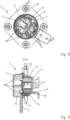
- FIG. 8 shows a top view of a grounding contact 1 according to the invention with several brush shafts 4 and brushes 6.
- the base plate 3 has a substantially round shape or, in plan view, pan-shaped, which is due to the connections for the power supply.
- the base plate 3 has three brush shaft receptacles 5.
- Two brush shaft receptacles 5 lie opposite each other, with a third brush shaft receptacle 5 being arranged to the side of the first two brush shaft receptacles 5.
- the brush shafts 4 pass through the brush shaft receptacles 5 of the base plate 3 as separate components and are connected to it in a form-fitting and clamping manner via clamping tongues 11.
- Brushes 6 are arranged in each of the three brush shafts 4, which have the above mentioned Contact means 8 and are connected to the base plate 3 by means of the connections 9.
- FIG. 9 shows the section BB through Figure 8.
- Figure 9 shows the spring element 15 in the form of a roller band spring, which pushes the respective brush 6 against a relatively movable component 18 (slip ring) for power transmission. Furthermore shows Figure 9 that the grounding contact 1 with its brush shafts 4 passes through a holder 19. The holder 19 runs essentially parallel to the base plate 3.
Landscapes
- Motor Or Generator Current Collectors (AREA)
- Elimination Of Static Electricity (AREA)
Description
- Die Erfindung betrifft einen Erdungskontakt zur kontrollierten Lenkung von elektrischem Strom gemäß den Merkmalen des Patentanspruchs 1.
- Ein Erdungskontakt stellt eine niederohmige Brücke dar, die die kritischen Stellen eines Bauteils vor einer Beschädigung durch hohe Ströme schützt. In der Bahntechnik leiten Erdungskontakte Strom um kritische Stellen, wie z.B. Radlager herum.
- Aus der
DE 41 27 336 A1 ist eine Haltevorrichtung für Bürsten bekannt, die an Schienenfahrzeugen einen Rückstrom- und/oder Erdungskontakt zwischen relativ zueinander bewegten Teilen bilden. Die Haltevorrichtung weist mindestens einen metallischen Bürstenschacht auf, in dem eine Bürste verschiebbar angeordnet ist sowie wenigstens eine Druckvorrichtung, die in einer Ausnehmung an dem Bürstenschacht gehalten ist und auf ein Ende der Bürste eine Kraft ausübt. Der Bürstenschacht geht einstückig in eine Grundplatte über. Die Grundplatte mit dem Bürstenschacht ist ein Gussbauteil. - Die Fertigung eines solchen Bürstenhalters ist unter anderem wegen der Innenkontur des Bürstenschachtes aufwändig. Der gegossene Bürstenschacht muss mit relativ hohem Zerspanungsvolumen geräumt werden. Die Werkzeuge sind kostenintensiv. Ein weiterer Nachteil besteht darin, dass die Bürstenschächte keiner Standardisierung unterliegen und somit die Abmaße der Bürstenschächte variieren können.
- Teilweise werden die Bürstenschächte mittels einer Madenschraube oder einer Überwurfmutter an tragenden Bauteilen befestigt. Aus dem Stand der Technik ist das Einschieben von Bürstenhaltern in taschenartige Aussparungen eines zylindrischen Gehäuses bekannt, wobei die Bürstenhalter durch einen Deckel in Position gehalten werden. Bürstenhalter können einstückig durch Spritzgießen aus Kunststoff hergestellt sein oder auch über rein kraftschlüssige Schraubverbindungen mit einem Gehäuse verbunden sein. Weitere Ausführungsformen von Bürstenhaltern, die allerdings teilweise direkt an einem Gehäuse einer Maschine befestigt sind, werden in der
WO 02/075899 A1 DE 10 2004 004 745 A1 ,EP 1 136 342 A2 ,US 3,431,446 A ,US 4,876,475 A ,DE 25 41 457 A1 undDE 1 122 625 B beschrieben. - Der Erfindung liegt die Aufgabe zugrunde, einen Erdungskontakt mit einem kompakten und robusten Bürstenhalter aufzuzeigen, der kostengünstig und einfach herstellbar sowie für eine Standardisierung geeignet ist.
- Die Aufgabe wird durch einen Erdungskontakt mit einem Bürstenhalter mit den Merkmalen des Anspruchs 1 gelöst.
- Vorteilhafte Weiterbildungen der Erfindung sind in den abhängigen Ansprüchen angegeben.
- Die Erfindung betrifft einen Erdungskontakt zur kontrollierten Lenkung von elektrischem Strom. Er umfasst einen Bürstenhalter mit einer Grundplatte und mit wenigstens einem Bürstenschacht zur Aufnahme einer Bürste. Der wenigstens eine Bürstenschacht ist mit der Grundplatte formschlüssig verbunden.
- Der Vorteil des erfindungsgemäßen Erdungskontakts ist die modulare Bauweise bezüglich des Bürstenschachtes. Durch eine Aufteilung des Bürstenhalters in eine Grundplatte und einen davon getrennt zu fertigenden Bürstenschacht werden Kosten für die zerspanenden Bearbeitungsschritte reduziert. Die Grundplatte und der Bürstenschacht können getrennt voneinander durch Laser- und Wasserstrahlschneidverfahren hergestellt werden. Modell- und Werkzeugkosten für die Kokille beim Gussverfahren entfallen. Die Bearbeitung mit einem Laser- und Wasserstrahlverfahren führt zu einem geringeren Zerspanungsvolumen. Es muss nicht mehr der gesamte Bürstenschacht zerspanend geräumt werden. Durch das modulare Bauprinzip des Bürstenhalters können die Flexibilität des Fertigungsverfahrens verbessert und die Fertigungszeiten verringert werden. Erfindungsgemäß ist es durch das modulare Bauprinzip des Bürstenhalters möglich, den Bürstenschacht unabhängig von der Gestaltung der Grundplatte zu standardisieren und als Massenprodukt herzustellen.
- Die Erfindung sieht vor, den Bürstenschacht als Standardkomponente für die jeweils gängigen Bürsten mit den Abmaßen 40 x 20 mm oder 32 x 12,5 mm auszuführen. Standardisierte Bürstenschächte mit anderen Abmaßen können bei der Erfindung ebenso zum Einsatz kommen. Bei den Bürsten handelt es sich bevorzugt um Metall-Graphitbürsten, die auch als Kohlebürsten bezeichnet werden. Die Bürsten können jedoch auch aus anderen Metallen oder Metalllegierungen mit hoher elektrischer Leitfähigkeit bestehen und z.B. Kupfer, Silber oder Molybdän enthalten.
- Der Erdungskontakt weist Kontaktmittel in Form von Litzen auf, die an die Grundplatte anschließbar sind und den elektrischen Strom an die Bürste leiten. Die Litzen sind flexibel und gestatten die Nachführung der Bürsten unter dem Einfluss einer Federkraft. Die Verbindung zwischen der Grundplatte und den Litzen erfolgt über Rohrkabelschuhe an den Litzen, die darüber mit der Grundplatte elektrisch leitend verschraubbar sind.
- Erfindungswesentlich ist die formschlüssige Verbindung zwischen Grundplatte und Bürstenschacht. Die Grundplatte weist zur Aufnahme des mindestens einen Bürstenschachts mindestens eine Bürstenschachtaufnahme auf. Durch die formschlüssige Verbindung von Grundplatte mit Bürstenschacht ist eine einfache Montage und bei Bedarf ein einfacher Austausch des Bürstenschachts möglich, z.B. wenn der Bürstenschacht beschädigt oder verschlissen sein sollte. Die formschlüssige Verbindung ist lösbar.
- Die tragende Grundplatte ist bevorzugt eine flache Platte aus einem elektrisch leitfähigen Material, insbesondere Metall.Der Bürstenschacht weist Klemmzungen auf, über welche der Bürstenschacht an der Grundplatte klemmgehaltert ist. Die Klemmzungen besitzen an ihren freien Enden Haken, welche hinter einen Rand der Bürstenschachtaufnahme in der Grundplatte greifen. Die Klemmzungen sind bevorzugt auf wenigstens drei Seiten des Bürstenschachts angeordnet. Da die Bürsten im Wesentlichen rechteckig sind, besitzt auch der Bürstenschacht einen im Wesentlichen rechteckigen Querschnitt. Ideal ist eine diametrale Anordnung von Klemmzungen. Auch eine Anordnung von drei Klemmzungen ermöglicht eine hinreichende Fixierung des Bürstenschachts. Eine formschlüssige Verbindung mit Klemmzungen hat den Vorteil, dass eine Verbindung zwischen der Grundplatte und dem Bürstenschacht ohne weitere Befestigungsmittel, wie z.B. Schrauben, Stifte oder Niete möglich ist und der Einsatz von Werkzeugen dadurch entfällt. Das erleichtert die Montage. Die Klemmkraft der Klemmzungen ist so groß gewählt, dass diese nicht durch zusätzliche Sicherungsmittel gegen Zurückfedern gesichert werden müssen.
- Der Bürstenschacht besitzt eine Stützfläche zur unterseitigen Abstützung an der Grundplatte. Die Stützfläche befindet sich bevorzugt benachbart den feststehenden Enden der Klemmzungen. Dadurch ist der Bürstenschacht in senkrechter Richtung zur Grundplatte klemmend gehalten.
- Der Bürstenschacht durchsetzt die Bürstenschachtaufnahme vollständig. Die Klemmzungen bzw. Haken überragen die Grundplatte. Durch eine Kombination aus formschlüssiger und klemmender Verbindung, ist der Bürstenschacht sicher fixiert und es wird eine korrekte Führung der Bürste gewährleistet.
- Die Grundplatte kann für mehrere Bürsten eine entsprechende Anzahl von Bürstenschachtaufnahmen aufweisen. Dadurch können größere Ströme übertragen werden. Die Betriebssicherheit wird ebenfalls erhöht. In bevorzugter Weise weist die Grundplatte drei Bürstenschachtaufnahmen auf. Die einzelnen Bürstenschächte können dabei bevorzugt separat gefertigt sein. Es ist auch möglich, mehrere Bürstenschächte als ein gemeinsames Bauteil zu fertigen, das dann mit der Grundplatte verbunden wird.
- Um in Längsrichtung des Bürstenschachts eine Federkraft auf die Bürste im Bürstenschacht auszuüben, ist ein Federelement vorgesehen, das bevorzugt als Rollbandfeder ausgebildet ist. Das Federelement hat die Aufgabe eine Federkraft auf die Bürste auszuüben, so dass die Bürste ständig zur Stromübertragung an einem Schleifkörper anliegt. Bevorzugt ist das Federelement im Bürstenschacht befestigt. Hierzu wird ein Federhalter in dem Bürstenschacht montiert, sodass die Haltekraft für das Federelement von dem Bürstenschacht selbst aufgenommen wird. Es werden keine Kräfte in die Grundplatte eingeleitet. Der Bürstenschacht einschließlich des Federhalters und des Federelements bilden eine eigenständige Baugruppe, die zur Kopplung mit der Grundplatte vorgesehen ist.
- Es ist nicht zu erforderlich, dass der Bürstenschacht elektrisch leitend ausgeführt ist. Die Bürsten sind über die Litzen Strom führend mit der Grundplatte verbunden. Der Bürstenschacht kann daher aus elektrisch nicht leitendem Material bestehen, insbesondere aus einem Kunststoff. Dies hat den Vorteil, dass der gesamte Erdungskontakt leichter und auch günstiger in seiner Herstellung ist. Der Bürstenschacht ist insbesondere als Spritzgussbauteil kostengünstig herstellbar. Ein weiterer Vorteil besteht in den guten Gleiteigenschaften von einigen Kunststoffen, was wiederum optimal für eine Führung der Bürste innerhalb des Bürstenschachts ist.
- Um den Erdungskontakt vor mechanische Beanspruchungen, wie z.B. Steinschlag zu schützen, weist der Erdungskontakt bevorzugt einen Deckel auf, der die Bürste mit elektrischen Anschlüssen, Kontakten und Litzen schützt. Der Deckel ist dabei an der Grundplatte kraft- und/oder formschlüssig beispielsweise mittels Schrauben befestigbar.
- Die Erfindung wird nachfolgend anhand von in schematischen Zeichnungen dargestellten Ausführungsbeispielen näher erläutert. Es zeigen:
- Figur 1
- eine Seitenansicht eines aus dem Stand der Technik bekannten Bürstenhalters;
- Figur 2
- eine Aufsicht eines Bürstenhalters gemäß
Figur 1 ; - Figur 3 und 4
- eine perspektivische Ansicht eines erfindungsgemäßen Erdungskontakts mit Deckel;
- Figur 5
- eine Aufsicht auf einen erfindungsgemäßen Erdungskontakt ohne Deckel;
- Figur 6
- einen Axialschnitt eines erfindungsgemäßen Erdungskontakt gemäß
Figur 5 mit Deckel; - Figur 7
- eine Schnittdarstellung eines erfindungsgemäßen Erdungskontakts gemäß
Figur 5 mit Deckel; - Figur 8
- eine Aufsicht auf einen erfindungsgemäßen Erdungskontakt mit mehreren Bürstenschächten und Bürsten und
- Figur 9
- eine Schnittdarstellung durch einen erfindungsgemäßen Erdungskontakt gemäß
Figur 8 . - Die
Figuren 1 und 2 zeigen einen Bürstenhalter 2, wie er aus dem Stand der Technik bekannt ist. Der Bürstenhalter 2 weist eine Grundplatte 3 und einen Bürstenschacht 4 auf. Die Grundplatte 3 und der Bürstenschacht 4 sind einstückig und werkstoffeinheitlich ausgebildet. Der dargestellte Bürstenschacht 4 dient zur Aufnahme einer nicht näher dargestellten Bürste. - Die
Figuren 3 und 4 zeigen jeweils perspektivische Ansichten eines erfindungsgemäßen Erdungskontakts 1. Der Erdungskontakt 1 besitzt eine Grundplatte 3, einen Bürstenschacht 4 und eine Bürste 6. Die Grundplatte 3 und der Bürstenschacht 4 sind erfindungsgemäß nicht einstückig ausgebildet. Die Grundplatte 3 besitzt eine Bürstenschachtaufnahme 5, in welche der Bürstenschacht 4 eingesetzt ist. Dabei entspricht die Außenkontur des Bürstenschachtes 4 der Kontur der Bürstenschachtaufnahme 5 in der Grundplatte 3, so dass ein passgenauer Sitz des Bürstenschachtes 4 innerhalb der Bürstenschachtaufnahme 5 der Grundplatte 3 gewährleistet ist. Ein oberhalb der Grundplatte 3 liegender Bereich ist durch einen Deckel 7 geschützt, der mittels Schrauben an der Grundplatte 3 befestigt ist. -
Figur 3 zeigt, dass die Bürste 6 mit einem Ende aus dem Bürstenschacht 4 hinausragt. Dieses eine Ende der Bürste 6 ist in Kontakt mit einem nicht dargestellten Bauteil (Schleifring) um elektrischen Strom über dieses Bauteil abzuleiten.Figur 6 zeigt auf einer Unterseite der Grundplatte 3 eine elektrisch isolierende Unterplatte 16 mit einer mittig angeordneten Aussparung für den Bürstenschacht 4. -
Figur 5 zeigt den erfindungsgemäßen Erdungskontakt 1 derFiguren 3 und 4 in einer Aufsicht ohne Deckel 7. Die Grundplatte 3 weist eine rechteckige Form auf. In der Mitte der Grundplatte 3 ist die Bürstenschachtaufnahme 5 zur Aufnahme des Bürstenschachts 4 angeordnet. In dem Bürstenschacht 4 ist die Bürste 6 angeordnet. - Elektrische Kontaktmittel 8 in Form von flexiblen Litzen sind über zwei Anschlüsse 9 an der Grundplatte 3 des Erdungskontakts 1 angeschlossen und stellen die stromleitende Verbindung zwischen der Grundplatte 3 und der Bürste 6 her. In diesem Ausführungsbeispiel weist die Bürste 6 zwei Kontaktmittel 8 (Litzen) auf, wobei die Kabelschuhe 9 mit Schrauben an der Grundplatte 3 befestigt sind. An den jeweils gegenüberliegenden Enden der Grundplatte 3 sind Aufnahmen für Rohrkabelschuhe 10 vorgesehen, die ebenfalls mittels Schrauben an der Grundplatte 3 befestigt sind. Über nicht näher dargestellte Zuleitungen wird der elektrische Strom über die angeschraubten Rohrkabelschuhe 10 der Grundplatte 3 zur Weiterleitung zugeführt.
-
Figur 6 stellt einen Schnitt entlang der Linie A-A gemäßFigur 5 dar. Im Unterschied zuFigur 5 ist der Erdungskontakt 1 mit einem Deckel 7 verschlossen, wobei der Deckel 7 die Kontaktmittel 8, die Bürste 6 und einen großen Bereich der Grundplatte 3 abdeckt. Der Bürstenschacht 4 durchsetzt die Bürstenschachtaufnahme 5 vollständig. Der Bürstenschacht 4 ist mittels Klemmzungen 11 an der Grundplatte 3 klemmgehaltert (Figuren 6 und7 ). An ihren freien Enden 12 weisen die Klemmzungen 11 Haken 17 auf, die an einer Oberseite der Grundplatte 3 greifen. - Die Oberseite der Grundplatte 3 ist die Seite, auf der der Deckel 7 befestigt wird. Die Unterseite der Grundplatte 3 ist die der Oberseite gegenüberliegende Seite der Grundplatte 3. Die Begriffe Oberseite und Unterseite bzw. oben und unten sind nicht einschränkend für die Einbaulage des Erdungskontaktes 1.
- Der Bürstenschacht 4 weist zur unterseitigen Abstützung der Grundplatte 3 eine Stützfläche 13 auf. Sie besteht im Wesentlichen aus einem Vorsprung bzw. eine Aussparung in dem Bürstenschacht 4, die zusammen mit dem Haken 17 der Klemmzunge 11 eine formschlüssige Verbindung zur Aufnahme für die Grundplatte 3 darstellt (
Figur 7 ). - Die
Figur 7 zeigt eine weitere Schnittdarstellung des Erdungskontakts 1 gemäßFigur 5 mit Deckel 7.Figur 7 zeigt einen Federhalter 14 zur Aufnahme eines Federelements 15. Der Federhalter 14 ist formschlüssig mit dem Bürstenschacht 4 verbunden. Der Federhalter 14 durchsetzt dabei zusammen mit dem Federelement 15 und mit dem Bürstenschacht 4 die Bürstenschachtaufnahme 5. Das Federelement 15 ist eine Rollbandfeder, die von der Oberseite auf die Bürste 6 drückt. Im Betriebsfall liegt ein Ende der Bürste 6 an einem nicht dargestellten rotierenden Bauteil an, so dass die Bürste 6 abnutzt. Die Bürste 6 ist verschiebbar in dem Bürstenschacht 4 gelagert, wobei die von dem Federelement ausgeübte Kraft die Bürste 6 gegen das rotierende Bauteil drückt. -
Figur 8 zeigt eine Aufsicht auf einen erfindungsgemäßen Erdungskontakt 1 mit mehreren Bürstenschächten 4 und Bürsten 6. Die Grundplatte 3 weist eine im Wesentlichen runde bzw. in der Draufsicht pfannenförmige Form auf, was auf die Anschlüsse zur Stromzufuhr zurückzuführen ist. Die Grundplatte 3 weist drei Bürstenschachtaufnahmen 5 auf. Zwei Bürstenschachtaufnahmen 5 liegen sich gegenüber, wobei eine dritte Bürstenschachtaufnahme 5 seitlich der ersten beiden Bürstenschachtaufnahmen 5 angeordnet ist. Auch in diesem Ausführungsbeispiel durchsetzen die Bürstenschächte 4 als separate Bauteile die Bürstenschachtaufnahmen 5 der Grundplatte 3 und sind mit dieser über Klemmzungen 11 formschlüssig und klemmend verbunden. In den drei Bürstenschächten 4 sind jeweils Bürsten 6 mit angeordnet, die über die besagten Kontaktmittel 8 und mittels der Anschlüsse 9 an die Grundplatte 3 angeschlossen sind. - Die
Figur 9 zeigt den Schnitt B-B durchFigur 8. Figur 9 zeigt das Federelement 15 in Form einer Rollbandfeder, welche die jeweilige Bürste 6 gegen ein relativ bewegliches Bauteil 18 (Schleifring) zur Stromübertragung drängt. Ferner zeigtFigur 9 , dass der Erdungskontakt 1 mit seinen Bürstenschächten 4 eine Halterung 19 durchsetzt. Die Halterung 19 verläuft im Wesentlichen parallel zur Grundplatte 3. -
- 1 -
- Erdungskontakt
- 2 -
- Bürstenhalter
- 3 -
- Grundplatte
- 4 -
- Bürstenschacht
- 5 -
- Bürstenschachtaufnahme
- 6 -
- Bürste
- 7 -
- Deckel
- 8 -
- Kontaktmittel
- 9 -
- Kabelschuh
- 10 -
- Rohrkabelschuh
- 11 -
- Klemmzungen
- 12 -
- freies Ende zu 11
- 13 -
- Stützfläche zu 4
- 14 -
- Federhalter
- 15 -
- Federelement
- 16 -
- Unterplatte
- 17 -
- Haken
- 18 -
- Bauteil
- 19 -
- Halterung
- F -
- Federkraft
Claims (6)
- Erdungskontakt zur kontrollierten Lenkung von elektrischem Strom mit einem Bürstenhalter (2), wobei der Bürstenhalter (2) eine Grundplatte (3) und wenigstens einen Bürstenschacht (4) zur Aufnahme einer Bürste (6) umfasst und wobei der wenigstens eine Bürstenschacht (4) formschlüssig mit der Grundplatte (3) verbunden ist, wobei der Bürstenschacht (4) Klemmzungen (11) aufweist, über welche der Bürstenschacht (4) an der Grundplatte (3) klemmgehaltert ist, wobei die Klemmzungen (11) an ihren freien Enden (12) Haken (17) besitzen, welche hinter einen Rand einer Bürstenschachtaufnahme (5) in der Grundplatte (3) greifen, wobei der Bürstenschacht (4) eine Stützfläche (13) besitzt, zur unterseitigen Abstützung an der Grundplatte (3), wobei der Bürstenschacht (4) die Bürstenschachtaufnahme (5) vollständig durchsetzt, wobei die formschlüssige Verbindung mit den Klemmzungen (11) dazu ausgebildet ist, eine Verbindung zwischen der Grundplatte (3) und dem wenigstens einen Bürstenschacht (4) ohne Schrauben und den Einsatz von Werkzeugen herzustellen.
- Erdungskontakt nach Anspruch 1, dadurch gekennzeichnet, dass die Klemmzungen (11) auf wenigstens drei Seiten des Bürstenschachts (4) angeordnet sind.
- Erdungskontakt nach Anspruch 1 oder 2, dadurch gekennzeichnet, dass die Grundplatte (3) mehrere Bürstenschachtaufnahmen (5) aufweist.
- Erdungskontakt nach einem der Ansprüche 1 bis 3, dadurch gekennzeichnet, dass in dem Bürstenschacht (4) ein Federelement (15) angeordnet ist, um in Längsrichtung des Bürstenschafts (4) eine Federkraft (F) auf die Bürste (6) im Bürstenschacht (4) auszuüben.
- Erdungskontakt nach einem der Ansprüche 1 bis 4, dadurch gekennzeichnet, dass das Federelement (15) im Bürstenschacht (4) befestigt ist.
- Erdungskontakt nach einem der Ansprüche 1 bis 5, dadurch gekennzeichnet, dass der Bürstenschacht (4) aus Kunststoff besteht.
Applications Claiming Priority (2)
| Application Number | Priority Date | Filing Date | Title |
|---|---|---|---|
| DE102017113911.7A DE102017113911B4 (de) | 2017-06-23 | 2017-06-23 | Erdungskontakt |
| PCT/DE2018/100374 WO2018233749A1 (de) | 2017-06-23 | 2018-04-19 | Erdungskontakt |
Publications (3)
| Publication Number | Publication Date |
|---|---|
| EP3642910A1 EP3642910A1 (de) | 2020-04-29 |
| EP3642910B1 true EP3642910B1 (de) | 2023-11-08 |
| EP3642910C0 EP3642910C0 (de) | 2023-11-08 |
Family
ID=62116157
Family Applications (1)
| Application Number | Title | Priority Date | Filing Date |
|---|---|---|---|
| EP18722385.4A Active EP3642910B1 (de) | 2017-06-23 | 2018-04-19 | Erdungskontakt |
Country Status (4)
| Country | Link |
|---|---|
| EP (1) | EP3642910B1 (de) |
| CN (1) | CN110462945B (de) |
| DE (1) | DE102017113911B4 (de) |
| WO (1) | WO2018233749A1 (de) |
Citations (3)
| Publication number | Priority date | Publication date | Assignee | Title |
|---|---|---|---|---|
| DE1122625B (de) * | 1956-01-02 | 1962-01-25 | Hollandse Signaalapparaten Bv | Elektrischer Apparat mit einer von einer Druckfeder an einen Kommutator oder Schleifring anzulegenden Buerste und einem Buerstenhalter |
| DE2541457A1 (de) * | 1974-09-13 | 1976-04-08 | Itw Fastex Italia Spa | Buerstenhalter fuer gleichstrommotoren |
| US4876475A (en) * | 1988-04-28 | 1989-10-24 | Sunbeam Corporation | Brush holder with plastic cup to retain biasing spring |
Family Cites Families (18)
| Publication number | Priority date | Publication date | Assignee | Title |
|---|---|---|---|---|
| US3431446A (en) * | 1967-07-25 | 1969-03-04 | Rae Motor Corp | Electric motor brush holder,cap and spring |
| JPS594819U (ja) * | 1982-07-01 | 1984-01-12 | 日本サ−ボ株式会社 | 軸受 |
| FR2615666B1 (fr) * | 1987-05-21 | 1989-08-18 | Peugeot Aciers Et Outillage | Plaque porte-balais perfectionnee notamment pour moteur electrique |
| JPH0448134Y2 (de) * | 1987-05-29 | 1992-11-12 | ||
| JPH0732568B2 (ja) * | 1989-05-16 | 1995-04-10 | アスモ株式会社 | モータのブラシ保持構造 |
| DE4127336A1 (de) | 1991-08-19 | 1993-02-25 | Schunk Metall & Kunststoff | Haltevorrichtung fuer an schienenfahrzeugen als rueckstrom- und/oder erdungskontakt eingesetzte buersten und verfahren zur herstellung einer solchen haltevorrichtung |
| CN1046603C (zh) * | 1994-04-28 | 1999-11-17 | 西门子加拿大有限公司 | 电刷支架组件 |
| US5717271A (en) * | 1995-01-27 | 1998-02-10 | Mitsuba Corporation | Brush holder device and method of molding same |
| DE19934558C2 (de) * | 1999-07-22 | 2001-12-13 | Temic Auto Electr Motors Gmbh | Bürstenhalter für einen Kollektormotor |
| FR2802727B1 (fr) * | 1999-12-20 | 2002-01-18 | Valeo Equip Electr Moteur | Boitier du moteur electrique d'un demarreur comportant un bourrelet d'etancheite et de centrage et demarreur comportant un tel boitier |
| DE10012739B4 (de) * | 2000-03-16 | 2004-12-30 | Schunk Metall Und Kunststoff Gmbh | Erdungskontakt sowie Verfahren zur Herstellung eines Gleitkörpers wie einer Kontaktscheibe eines Erdungskontaktes |
| DE10013491C2 (de) * | 2000-03-20 | 2002-10-24 | Schunk Metall & Kunststoff | Erdungskontakt |
| BR0110839A (pt) * | 2001-03-17 | 2003-03-11 | Bosch Gmbh Robert | Sistema acionador e respectivamente processo para a montagem de um sistema acionador |
| DE102004004745A1 (de) * | 2004-01-30 | 2005-08-18 | Robert Bosch Gmbh | Bürstenhalter für eine Elektromaschine |
| JP4333754B2 (ja) * | 2007-02-21 | 2009-09-16 | 株式会社デンソー | 車両用交流発電機 |
| CN201941802U (zh) * | 2010-12-27 | 2011-08-24 | 南车青岛四方机车车辆股份有限公司 | 轨道车辆抱轴式接地装置 |
| EP2748049A1 (de) * | 2011-08-26 | 2014-07-02 | Aktiebolaget SKF | Anordnung mit rotierenden teilen mit leiterflüssigkeit für erdrückleitung |
| CN203119260U (zh) * | 2012-12-07 | 2013-08-07 | 谢佐凌 | 一种碳刷架 |
-
2017
- 2017-06-23 DE DE102017113911.7A patent/DE102017113911B4/de active Active
-
2018
- 2018-04-19 WO PCT/DE2018/100374 patent/WO2018233749A1/de not_active Ceased
- 2018-04-19 EP EP18722385.4A patent/EP3642910B1/de active Active
- 2018-04-19 CN CN201880021331.XA patent/CN110462945B/zh active Active
Patent Citations (3)
| Publication number | Priority date | Publication date | Assignee | Title |
|---|---|---|---|---|
| DE1122625B (de) * | 1956-01-02 | 1962-01-25 | Hollandse Signaalapparaten Bv | Elektrischer Apparat mit einer von einer Druckfeder an einen Kommutator oder Schleifring anzulegenden Buerste und einem Buerstenhalter |
| DE2541457A1 (de) * | 1974-09-13 | 1976-04-08 | Itw Fastex Italia Spa | Buerstenhalter fuer gleichstrommotoren |
| US4876475A (en) * | 1988-04-28 | 1989-10-24 | Sunbeam Corporation | Brush holder with plastic cup to retain biasing spring |
Also Published As
| Publication number | Publication date |
|---|---|
| CN110462945B (zh) | 2022-08-09 |
| EP3642910A1 (de) | 2020-04-29 |
| EP3642910C0 (de) | 2023-11-08 |
| CN110462945A (zh) | 2019-11-15 |
| WO2018233749A1 (de) | 2018-12-27 |
| DE102017113911B4 (de) | 2022-03-24 |
| DE102017113911A1 (de) | 2018-12-27 |
Similar Documents
| Publication | Publication Date | Title |
|---|---|---|
| DE102010035868B3 (de) | Elektrische Komponente | |
| EP2878041B1 (de) | Kontaktelement | |
| EP3316402B1 (de) | Flachkontaktbuchse | |
| DE102018100825B4 (de) | Landseitiger Elektrofahrzeug-Ladestecker | |
| EP2380241B1 (de) | Kontaktierungsstecker sowie kontaktierungssteckverbindung | |
| EP1981132B1 (de) | Schirmhülse | |
| EP0959529A2 (de) | Elektrische Anschlussbaueinheit | |
| DE102004005950A1 (de) | Schutz- und Führungsvorrichtung für ein Kabel oder einen Schlauch | |
| DE69712850T2 (de) | Vorrichtung zur mechanischen und elektrischen Verbindung von zwei Teilbaugruppen eines Kraftfahrzeugwechselstromgenerators | |
| DE102011053979B4 (de) | Schleifkontakteinrichtung einer Erodiereinrichtung einer kombinierten Schleif- und Erodiermaschine und Verfahren zur Herstellung einer Schleifkontakteinrichtung | |
| EP3262717B1 (de) | Steckverbindung für eine elektrische verbindung | |
| EP3981046B1 (de) | Modularer leiterkartensteckverbinder | |
| DE102015110428B4 (de) | Gleitkontaktelement | |
| DE202010015731U1 (de) | Abstützvorrichtung für eine elektrische Reihenklemmenanordnung | |
| EP3744278A1 (de) | Elektrochirurgisches instrument und verfahren zu dessen herstellung | |
| DE102017113911B4 (de) | Erdungskontakt | |
| EP3715073A1 (de) | Säge | |
| EP3317922B1 (de) | Gleitelement zur kontaktierung von leiterkarten | |
| EP3292592B1 (de) | Batterieklemme und verfahren zur herstellung einer batterieklemme | |
| WO2018033540A1 (de) | Dünner leiter mit durchgängen | |
| DE3800568C2 (de) | ||
| DE69302356T2 (de) | Elektrodynamische Maschine mit Blechbügelbürsten | |
| DE102018120104B4 (de) | Steckverbinder zum Bereitstellen eines elektrischen Anschlusses und Verfahren | |
| DE102007062956B3 (de) | Montagehilfe für das Montieren von wenigstens zwei Kabelschuhen | |
| EP1467432A1 (de) | Kontaktadapter für die Kontaktierung einer Antennenstruktur eines Fahrzeuges |
Legal Events
| Date | Code | Title | Description |
|---|---|---|---|
| STAA | Information on the status of an ep patent application or granted ep patent |
Free format text: STATUS: UNKNOWN |
|
| STAA | Information on the status of an ep patent application or granted ep patent |
Free format text: STATUS: THE INTERNATIONAL PUBLICATION HAS BEEN MADE |
|
| PUAI | Public reference made under article 153(3) epc to a published international application that has entered the european phase |
Free format text: ORIGINAL CODE: 0009012 |
|
| STAA | Information on the status of an ep patent application or granted ep patent |
Free format text: STATUS: REQUEST FOR EXAMINATION WAS MADE |
|
| 17P | Request for examination filed |
Effective date: 20190909 |
|
| AK | Designated contracting states |
Kind code of ref document: A1 Designated state(s): AL AT BE BG CH CY CZ DE DK EE ES FI FR GB GR HR HU IE IS IT LI LT LU LV MC MK MT NL NO PL PT RO RS SE SI SK SM TR |
|
| AX | Request for extension of the european patent |
Extension state: BA ME |
|
| DAV | Request for validation of the european patent (deleted) | ||
| DAX | Request for extension of the european patent (deleted) | ||
| STAA | Information on the status of an ep patent application or granted ep patent |
Free format text: STATUS: EXAMINATION IS IN PROGRESS |
|
| 17Q | First examination report despatched |
Effective date: 20210616 |
|
| REG | Reference to a national code |
Ref country code: DE Ref legal event code: R079 Free format text: PREVIOUS MAIN CLASS: H01R0039380000 Ipc: H01R0039390000 Ref country code: DE Ref legal event code: R079 Ref document number: 502018013609 Country of ref document: DE Free format text: PREVIOUS MAIN CLASS: H01R0039380000 Ipc: H01R0039390000 |
|
| GRAP | Despatch of communication of intention to grant a patent |
Free format text: ORIGINAL CODE: EPIDOSNIGR1 |
|
| STAA | Information on the status of an ep patent application or granted ep patent |
Free format text: STATUS: GRANT OF PATENT IS INTENDED |
|
| RIC1 | Information provided on ipc code assigned before grant |
Ipc: H01R 39/39 20060101AFI20230526BHEP |
|
| P01 | Opt-out of the competence of the unified patent court (upc) registered |
Effective date: 20230530 |
|
| INTG | Intention to grant announced |
Effective date: 20230623 |
|
| GRAS | Grant fee paid |
Free format text: ORIGINAL CODE: EPIDOSNIGR3 |
|
| GRAA | (expected) grant |
Free format text: ORIGINAL CODE: 0009210 |
|
| STAA | Information on the status of an ep patent application or granted ep patent |
Free format text: STATUS: THE PATENT HAS BEEN GRANTED |
|
| AK | Designated contracting states |
Kind code of ref document: B1 Designated state(s): AL AT BE BG CH CY CZ DE DK EE ES FI FR GB GR HR HU IE IS IT LI LT LU LV MC MK MT NL NO PL PT RO RS SE SI SK SM TR |
|
| REG | Reference to a national code |
Ref country code: GB Ref legal event code: FG4D Free format text: NOT ENGLISH |
|
| REG | Reference to a national code |
Ref country code: CH Ref legal event code: EP |
|
| REG | Reference to a national code |
Ref country code: DE Ref legal event code: R096 Ref document number: 502018013609 Country of ref document: DE |
|
| REG | Reference to a national code |
Ref country code: IE Ref legal event code: FG4D Free format text: LANGUAGE OF EP DOCUMENT: GERMAN |
|
| U01 | Request for unitary effect filed |
Effective date: 20231129 |
|
| U07 | Unitary effect registered |
Designated state(s): AT BE BG DE DK EE FI FR IT LT LU LV MT NL PT SE SI Effective date: 20231205 |
|
| P04 | Withdrawal of opt-out of the competence of the unified patent court (upc) registered |
Effective date: 20231201 |
|
| PG25 | Lapsed in a contracting state [announced via postgrant information from national office to epo] |
Ref country code: GR Free format text: LAPSE BECAUSE OF FAILURE TO SUBMIT A TRANSLATION OF THE DESCRIPTION OR TO PAY THE FEE WITHIN THE PRESCRIBED TIME-LIMIT Effective date: 20240209 |
|
| PG25 | Lapsed in a contracting state [announced via postgrant information from national office to epo] |
Ref country code: IS Free format text: LAPSE BECAUSE OF FAILURE TO SUBMIT A TRANSLATION OF THE DESCRIPTION OR TO PAY THE FEE WITHIN THE PRESCRIBED TIME-LIMIT Effective date: 20240308 |
|
| PG25 | Lapsed in a contracting state [announced via postgrant information from national office to epo] |
Ref country code: ES Free format text: LAPSE BECAUSE OF FAILURE TO SUBMIT A TRANSLATION OF THE DESCRIPTION OR TO PAY THE FEE WITHIN THE PRESCRIBED TIME-LIMIT Effective date: 20231108 |
|
| PG25 | Lapsed in a contracting state [announced via postgrant information from national office to epo] |
Ref country code: IS Free format text: LAPSE BECAUSE OF FAILURE TO SUBMIT A TRANSLATION OF THE DESCRIPTION OR TO PAY THE FEE WITHIN THE PRESCRIBED TIME-LIMIT Effective date: 20240308 Ref country code: GR Free format text: LAPSE BECAUSE OF FAILURE TO SUBMIT A TRANSLATION OF THE DESCRIPTION OR TO PAY THE FEE WITHIN THE PRESCRIBED TIME-LIMIT Effective date: 20240209 Ref country code: ES Free format text: LAPSE BECAUSE OF FAILURE TO SUBMIT A TRANSLATION OF THE DESCRIPTION OR TO PAY THE FEE WITHIN THE PRESCRIBED TIME-LIMIT Effective date: 20231108 |
|
| U20 | Renewal fee for the european patent with unitary effect paid |
Year of fee payment: 7 Effective date: 20240411 |
|
| PG25 | Lapsed in a contracting state [announced via postgrant information from national office to epo] |
Ref country code: RS Free format text: LAPSE BECAUSE OF FAILURE TO SUBMIT A TRANSLATION OF THE DESCRIPTION OR TO PAY THE FEE WITHIN THE PRESCRIBED TIME-LIMIT Effective date: 20231108 Ref country code: PL Free format text: LAPSE BECAUSE OF FAILURE TO SUBMIT A TRANSLATION OF THE DESCRIPTION OR TO PAY THE FEE WITHIN THE PRESCRIBED TIME-LIMIT Effective date: 20231108 Ref country code: NO Free format text: LAPSE BECAUSE OF FAILURE TO SUBMIT A TRANSLATION OF THE DESCRIPTION OR TO PAY THE FEE WITHIN THE PRESCRIBED TIME-LIMIT Effective date: 20240208 Ref country code: HR Free format text: LAPSE BECAUSE OF FAILURE TO SUBMIT A TRANSLATION OF THE DESCRIPTION OR TO PAY THE FEE WITHIN THE PRESCRIBED TIME-LIMIT Effective date: 20231108 |
|
| PG25 | Lapsed in a contracting state [announced via postgrant information from national office to epo] |
Ref country code: CZ Free format text: LAPSE BECAUSE OF FAILURE TO SUBMIT A TRANSLATION OF THE DESCRIPTION OR TO PAY THE FEE WITHIN THE PRESCRIBED TIME-LIMIT Effective date: 20231108 |
|
| PG25 | Lapsed in a contracting state [announced via postgrant information from national office to epo] |
Ref country code: SK Free format text: LAPSE BECAUSE OF FAILURE TO SUBMIT A TRANSLATION OF THE DESCRIPTION OR TO PAY THE FEE WITHIN THE PRESCRIBED TIME-LIMIT Effective date: 20231108 |
|
| PG25 | Lapsed in a contracting state [announced via postgrant information from national office to epo] |
Ref country code: SM Free format text: LAPSE BECAUSE OF FAILURE TO SUBMIT A TRANSLATION OF THE DESCRIPTION OR TO PAY THE FEE WITHIN THE PRESCRIBED TIME-LIMIT Effective date: 20231108 Ref country code: SK Free format text: LAPSE BECAUSE OF FAILURE TO SUBMIT A TRANSLATION OF THE DESCRIPTION OR TO PAY THE FEE WITHIN THE PRESCRIBED TIME-LIMIT Effective date: 20231108 Ref country code: RO Free format text: LAPSE BECAUSE OF FAILURE TO SUBMIT A TRANSLATION OF THE DESCRIPTION OR TO PAY THE FEE WITHIN THE PRESCRIBED TIME-LIMIT Effective date: 20231108 Ref country code: CZ Free format text: LAPSE BECAUSE OF FAILURE TO SUBMIT A TRANSLATION OF THE DESCRIPTION OR TO PAY THE FEE WITHIN THE PRESCRIBED TIME-LIMIT Effective date: 20231108 |
|
| REG | Reference to a national code |
Ref country code: DE Ref legal event code: R097 Ref document number: 502018013609 Country of ref document: DE |
|
| PLBE | No opposition filed within time limit |
Free format text: ORIGINAL CODE: 0009261 |
|
| STAA | Information on the status of an ep patent application or granted ep patent |
Free format text: STATUS: NO OPPOSITION FILED WITHIN TIME LIMIT |
|
| 26N | No opposition filed |
Effective date: 20240809 |
|
| PG25 | Lapsed in a contracting state [announced via postgrant information from national office to epo] |
Ref country code: MC Free format text: LAPSE BECAUSE OF FAILURE TO SUBMIT A TRANSLATION OF THE DESCRIPTION OR TO PAY THE FEE WITHIN THE PRESCRIBED TIME-LIMIT Effective date: 20231108 |
|
| PG25 | Lapsed in a contracting state [announced via postgrant information from national office to epo] |
Ref country code: MC Free format text: LAPSE BECAUSE OF FAILURE TO SUBMIT A TRANSLATION OF THE DESCRIPTION OR TO PAY THE FEE WITHIN THE PRESCRIBED TIME-LIMIT Effective date: 20231108 |
|
| REG | Reference to a national code |
Ref country code: CH Ref legal event code: PL |
|
| GBPC | Gb: european patent ceased through non-payment of renewal fee |
Effective date: 20240419 |
|
| P05 | Withdrawal of opt-out of the competence of the unified patent court (upc) changed |
Free format text: CASE NUMBER: APP_590421/2023 Effective date: 20231205 |
|
| PG25 | Lapsed in a contracting state [announced via postgrant information from national office to epo] |
Ref country code: GB Free format text: LAPSE BECAUSE OF NON-PAYMENT OF DUE FEES Effective date: 20240419 |
|
| PG25 | Lapsed in a contracting state [announced via postgrant information from national office to epo] |
Ref country code: GB Free format text: LAPSE BECAUSE OF NON-PAYMENT OF DUE FEES Effective date: 20240419 Ref country code: CH Free format text: LAPSE BECAUSE OF NON-PAYMENT OF DUE FEES Effective date: 20240430 |
|
| PG25 | Lapsed in a contracting state [announced via postgrant information from national office to epo] |
Ref country code: IE Free format text: LAPSE BECAUSE OF NON-PAYMENT OF DUE FEES Effective date: 20240419 |
|
| U20 | Renewal fee for the european patent with unitary effect paid |
Year of fee payment: 8 Effective date: 20250408 |
|
| PG25 | Lapsed in a contracting state [announced via postgrant information from national office to epo] |
Ref country code: CY Free format text: LAPSE BECAUSE OF FAILURE TO SUBMIT A TRANSLATION OF THE DESCRIPTION OR TO PAY THE FEE WITHIN THE PRESCRIBED TIME-LIMIT; INVALID AB INITIO Effective date: 20180419 |
|
| PG25 | Lapsed in a contracting state [announced via postgrant information from national office to epo] |
Ref country code: HU Free format text: LAPSE BECAUSE OF FAILURE TO SUBMIT A TRANSLATION OF THE DESCRIPTION OR TO PAY THE FEE WITHIN THE PRESCRIBED TIME-LIMIT; INVALID AB INITIO Effective date: 20180419 |
|
| U20 | Renewal fee for the european patent with unitary effect paid |
Year of fee payment: 9 Effective date: 20260408 |