EP3641064A1 - Verfahren zur herstellung einer batteriepolklemme, batteriepolklemme und batteriesensor - Google Patents
Verfahren zur herstellung einer batteriepolklemme, batteriepolklemme und batteriesensor Download PDFInfo
- Publication number
- EP3641064A1 EP3641064A1 EP19202320.8A EP19202320A EP3641064A1 EP 3641064 A1 EP3641064 A1 EP 3641064A1 EP 19202320 A EP19202320 A EP 19202320A EP 3641064 A1 EP3641064 A1 EP 3641064A1
- Authority
- EP
- European Patent Office
- Prior art keywords
- battery
- receptacle
- battery pole
- base body
- clamping
- Prior art date
- Legal status (The legal status is an assumption and is not a legal conclusion. Google has not performed a legal analysis and makes no representation as to the accuracy of the status listed.)
- Granted
Links
Images

Classifications
-
- H—ELECTRICITY
- H01—ELECTRIC ELEMENTS
- H01M—PROCESSES OR MEANS, e.g. BATTERIES, FOR THE DIRECT CONVERSION OF CHEMICAL ENERGY INTO ELECTRICAL ENERGY
- H01M50/00—Constructional details or processes of manufacture of the non-active parts of electrochemical cells other than fuel cells, e.g. hybrid cells
- H01M50/50—Current conducting connections for cells or batteries
- H01M50/543—Terminals
-
- H—ELECTRICITY
- H01—ELECTRIC ELEMENTS
- H01R—ELECTRICALLY-CONDUCTIVE CONNECTIONS; STRUCTURAL ASSOCIATIONS OF A PLURALITY OF MUTUALLY-INSULATED ELECTRICAL CONNECTING ELEMENTS; COUPLING DEVICES; CURRENT COLLECTORS
- H01R11/00—Individual connecting elements providing two or more spaced connecting locations for conductive members which are, or may be, thereby interconnected, e.g. end pieces for wires or cables supported by the wire or cable and having means for facilitating electrical connection to some other wire, terminal, or conductive member, blocks of binding posts
- H01R11/11—End pieces or tapping pieces for wires, supported by the wire and for facilitating electrical connection to some other wire, terminal or conductive member
- H01R11/28—End pieces consisting of a ferrule or sleeve
- H01R11/281—End pieces consisting of a ferrule or sleeve for connections to batteries
- H01R11/282—End pieces consisting of a ferrule or sleeve for connections to batteries comprising means for facilitating engagement or disengagement, e.g. quick release terminal
-
- G—PHYSICS
- G01—MEASURING; TESTING
- G01R—MEASURING ELECTRIC VARIABLES; MEASURING MAGNETIC VARIABLES
- G01R31/00—Arrangements for testing electric properties; Arrangements for locating electric faults; Arrangements for electrical testing characterised by what is being tested not provided for elsewhere
- G01R31/36—Arrangements for testing, measuring or monitoring the electrical condition of accumulators or electric batteries, e.g. capacity or state of charge [SoC]
- G01R31/364—Battery terminal connectors with integrated measuring arrangements
-
- G—PHYSICS
- G01—MEASURING; TESTING
- G01R—MEASURING ELECTRIC VARIABLES; MEASURING MAGNETIC VARIABLES
- G01R31/00—Arrangements for testing electric properties; Arrangements for locating electric faults; Arrangements for electrical testing characterised by what is being tested not provided for elsewhere
- G01R31/36—Arrangements for testing, measuring or monitoring the electrical condition of accumulators or electric batteries, e.g. capacity or state of charge [SoC]
- G01R31/385—Arrangements for measuring battery or accumulator variables
-
- H—ELECTRICITY
- H01—ELECTRIC ELEMENTS
- H01R—ELECTRICALLY-CONDUCTIVE CONNECTIONS; STRUCTURAL ASSOCIATIONS OF A PLURALITY OF MUTUALLY-INSULATED ELECTRICAL CONNECTING ELEMENTS; COUPLING DEVICES; CURRENT COLLECTORS
- H01R4/00—Electrically-conductive connections between two or more conductive members in direct contact, i.e. touching one another; Means for effecting or maintaining such contact; Electrically-conductive connections having two or more spaced connecting locations for conductors and using contact members penetrating insulation
- H01R4/28—Clamped connections, spring connections
- H01R4/38—Clamped connections, spring connections utilising a clamping member acted on by screw or nut
- H01R4/42—Clamping area to one side of screw only
-
- H—ELECTRICITY
- H01—ELECTRIC ELEMENTS
- H01R—ELECTRICALLY-CONDUCTIVE CONNECTIONS; STRUCTURAL ASSOCIATIONS OF A PLURALITY OF MUTUALLY-INSULATED ELECTRICAL CONNECTING ELEMENTS; COUPLING DEVICES; CURRENT COLLECTORS
- H01R43/00—Apparatus or processes specially adapted for manufacturing, assembling, maintaining, or repairing of line connectors or current collectors or for joining electric conductors
- H01R43/16—Apparatus or processes specially adapted for manufacturing, assembling, maintaining, or repairing of line connectors or current collectors or for joining electric conductors for manufacturing contact members, e.g. by punching and by bending
-
- H—ELECTRICITY
- H01—ELECTRIC ELEMENTS
- H01R—ELECTRICALLY-CONDUCTIVE CONNECTIONS; STRUCTURAL ASSOCIATIONS OF A PLURALITY OF MUTUALLY-INSULATED ELECTRICAL CONNECTING ELEMENTS; COUPLING DEVICES; CURRENT COLLECTORS
- H01R2201/00—Connectors or connections adapted for particular applications
- H01R2201/20—Connectors or connections adapted for particular applications for testing or measuring purposes
-
- H—ELECTRICITY
- H01—ELECTRIC ELEMENTS
- H01R—ELECTRICALLY-CONDUCTIVE CONNECTIONS; STRUCTURAL ASSOCIATIONS OF A PLURALITY OF MUTUALLY-INSULATED ELECTRICAL CONNECTING ELEMENTS; COUPLING DEVICES; CURRENT COLLECTORS
- H01R2201/00—Connectors or connections adapted for particular applications
- H01R2201/26—Connectors or connections adapted for particular applications for vehicles
-
- Y—GENERAL TAGGING OF NEW TECHNOLOGICAL DEVELOPMENTS; GENERAL TAGGING OF CROSS-SECTIONAL TECHNOLOGIES SPANNING OVER SEVERAL SECTIONS OF THE IPC; TECHNICAL SUBJECTS COVERED BY FORMER USPC CROSS-REFERENCE ART COLLECTIONS [XRACs] AND DIGESTS
- Y02—TECHNOLOGIES OR APPLICATIONS FOR MITIGATION OR ADAPTATION AGAINST CLIMATE CHANGE
- Y02E—REDUCTION OF GREENHOUSE GAS [GHG] EMISSIONS, RELATED TO ENERGY GENERATION, TRANSMISSION OR DISTRIBUTION
- Y02E60/00—Enabling technologies; Technologies with a potential or indirect contribution to GHG emissions mitigation
- Y02E60/10—Energy storage using batteries
Definitions
- the invention relates to a method for producing a battery pole terminal as well as a battery pole terminal and a battery sensor produced using this method.
- Battery sensors are used in vehicles to obtain information about the state of the battery, for example the state of charge of the battery.
- the battery sensor is usually attached to one of the battery poles of the vehicle battery, in particular to the negative pole of the battery.
- the battery sensor usually has a battery pole clamp which is plugged onto the battery pole and clamped thereon, for example by reducing the diameter of a receptacle for the battery pole by means of a clamping means.
- the battery pole clamp must ensure a reliable hold of the battery sensor on the vehicle battery in order to ensure a reliable power supply for the consumers in the vehicle and a reliable measurement of the battery condition.
- the battery sensor including the battery terminal, should be easy and inexpensive to manufacture.
- the object of the invention is to provide a method for producing a battery pole terminal, which enables simple and inexpensive production of a battery pole terminal.
- the object of the invention is also to provide an inexpensive and easy to manufacture battery terminal block provides a sufficiently stable hold on a battery pole of a vehicle battery.
- Another object of the invention is to provide a battery sensor with such a battery terminal.
- a battery pole clamp is provided to achieve the object, in particular for a vehicle battery in a vehicle, the battery pole clamp having a base body, with a clamping section for a battery pole of a battery, in particular a vehicle battery, and a receptacle provided for a clamping means on the clamping section.
- the clamping section encloses a, in particular essentially cylindrical, receiving space for the battery pole of the battery in the circumferential direction at least in sections and has an interruption in the circumferential direction with mutually facing edges, the receptacles on the edges of the clamping section are provided.
- the base body is formed in one piece, the clamping section being produced from the base body using a deep-drawing process and the receptacles being produced by reshaping the base body.
- the base body is preferably provided as a flat component, in particular as a flat sheet metal component, from which the clamping section and the receptacles are formed.
- the clamping section can be produced in a simple manner by a deep-drawing process.
- a deep-drawing process enables simple manufacture of an essentially cylindrical receiving space.
- the receiving space can also have a slightly comical design or expand conically at an insertion end for the battery pole, so that it is easier to push onto the battery pole.
- the forming process also makes it easy to produce the receptacles for the clamping device.
- a simple adaptation of the receptacles to the clamping means is possible. Thanks to the deep drawing process and the forming process, a simple and quick production of a battery terminal is possible.
- At least one receptacle can be produced by bending a section of the base body and then caulking a projection provided on the section in a recess in the base body.
- the section of the base body preferably has a projection and a recess is provided on the base body, into which the projection extends after the bending.
- the projection is caulked in particular in the recess after the bending.
- the recording can be made in a simple manner by bending. The subsequent caulking also reliably prevents the receptacle from deforming even under high forces.
- At least one receptacle can have a channel that is produced by bending a section of the base body.
- the clamping means has, for example, a clamping element and a counter-holder, which are each supported on one of the receptacles.
- the counterholder can be moved relative to the clamping element, whereby the receptacles are moved or pushed towards one another. This reduces the diameter of the receptacle, so that the battery pole clamp can jam on the battery pole and is thus held securely.
- the clamping element is, for example, a screw and the counter-holder has an internal thread corresponding to the screw.
- the screw can extend through a channel of the receptacle and be supported on the receptacle with the screw head.
- the counter-holder can be formed, for example, by the second receptacle, in which an internal thread is formed. However, the counterholder is preferably a nut which is supported on the associated receptacle.
- Both receptacles can preferably also each be formed by a channel, the longitudinal axes running essentially on a common straight line.
- the straight line runs in particular in a plane arranged perpendicular to the longitudinal axis of the receiving space and / or perpendicular to the longitudinal axis of the receiving space.
- both receptacles are formed by channels which lie essentially on a common straight line. This straight line preferably runs in a direction perpendicular to Axis of the pole receptacle and / or perpendicular to the axis of the pole receptacle.
- An anti-rotation device, an anti-displacement device and / or a loss device for the clamping device can be produced on at least one receptacle by a forming process.
- An anti-rotation device for the clamping means can thus be provided on at least one receptacle, the anti-rotation device preventing rotation of the clamping device about the longitudinal axis of the receptacle.
- the anti-rotation device is produced by a forming process.
- a tab or a projection of the base body is preferably bent over such that it prevents rotation of the clamping means or a part of the clamping means.
- the clamping device has a screw and a counter-holder with an internal thread corresponding to the screw. The anti-rotation device engages the counter-holder or the screw, so that the counter-holder or the screw is secured against twisting. If the freely rotatable element of the clamping element, i.e.
- the anti-twist device makes it possible to mount the battery pole clamp with a single tool. Since the anti-twist device is molded out of a section of the base body, simple manufacture of the anti-twist device and the entire battery pole terminal is possible.
- At least one receptacle can also be provided with a locking device for the clamping means, which prevents the clamping device from moving in the direction of the longitudinal axis, the locking device being secured, in particular, by a forming process is made.
- the locking device holds the clamping device, for example the screw and / or the counter-holder, reliably on the respective receptacle. If the screw and the counterholder are turned apart, for example to release the battery pole clamp from the battery pole, the receptacles, which are coupled in the displacement direction with the screw and / the counterholder, are moved apart with the screw and the counterholder.
- the tensioning means is released, that is to say, for example, when the screw and the counter-holder are unscrewed, the pole receptacle is also forced to widen, so that the battery pole clamp can be easily removed from the battery pool.
- the displacement lock thus enables the battery pole clamp to be positively opened by the interaction of the clamping means with the receptacles. Since the locking device is produced by a section of the base body, no additional assembly and / or joining steps are required.
- a captive securing device can be provided on at least one receptacle, which fixes the clamping means to the receptacle, the captive securing device being produced in particular by a forming process.
- the captive lock prevents the clamping device or parts of the clamping device from being lost, for example when the battery terminal is not installed.
- the locking process can also be produced in a simple manner by the forming process without additional assembly and / or joining steps.
- the anti-loss device, the anti-rotation device and the anti-displacement device can be formed together, in particular from one or more sections of the base body
- a clamping device is preferably inserted into the receptacles prior to the formation of an anti-rotation lock, a displacement lock and / or a loss lock. Then you can Securing against rotation, securing against displacement and / or securing against loss can be produced by bending or reshaping a section in such a way that the clamping means is held against rotation, against displacement or against loss of the respective receptacle.
- the subsequent shaping has the advantage that a particularly reliable fuse can be produced.
- a simple assembly of the clamping device is possible, since the anti-twist device, the anti-displacement device and / or the anti-loss device have not yet been manufactured or shaped and therefore cannot hinder the assembly process of the clamping device.
- At least one support surface for the clamping means is provided on each of the receptacles, the support surfaces being provided on sides of the receptacles facing away from one another.
- the clamping device is supported on these support surfaces and presses them against one another to clamp the battery pole clamp on a battery pole.
- the clamping means preferably each have a pressure surface which is supported in the respective support surface.
- the anti-twist device, the anti-displacement device and / or the anti-loss device can preferably be provided in the area of the spacing surfaces so that they can engage an element that forms the pressure surface.
- the pressure surface is formed on a flange, in particular with a torque transmission profile. The torque transmission profile can be used to engage the anti-rotation device or a tool.
- the receptacles are preferably mirror-symmetrical with respect to a plane extending through the longitudinal axis of the receptacle space.
- the base body from which the battery pole terminal is produced is preferably already mirror-symmetrical with respect to this plane.
- the battery poles are each arranged in a Polish slot, each of which is formed by an essentially cuboid recess in a corner of that of the vehicle battery.
- the Polish are usually formed on adjacent corners.
- the direction from which the battery pole terminal can be reached can vary. Due to the mirror-symmetrical construction, the battery pole clamp can be used on both battery poles, whereby only the direction in which the clamping device is used has to be adjusted.
- Sections for the anti-rotation lock, the anti-displacement lock and / or the captive lock are preferably provided on both receptacles, the sections required in each case being formed into an anti-twist lock, an anti-slip lock and / or a captive lock before and / or after the mounting of the clamping device.
- a battery sensor for a battery is also provided, in particular in a vehicle, with a detection device for detecting a battery parameter and with a battery pole terminal described above for contacting the battery sensor with a battery pole of the battery.
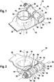
- a battery terminal 10 of a battery sensor 12 is shown.
- the battery pole terminal 10 is used to mount the battery sensor 12 on a battery pole of a battery, in particular a vehicle battery.
- the battery sensor 12 can detect battery parameters, for example the battery current, the battery voltage and / or the battery temperature. From the battery parameters, statements can be made about the state of the battery, for example the state of charge of the battery.
- the battery pole clamp 10 has a base body 14 on which a clamping section 16 for a battery pole and two receptacles 18 for a clamping means 20 are provided. Furthermore, the base body 14 has a line section 22, on which at least one detection device for at least one battery parameter can be provided.
- the clamping section 16 encloses a substantially cylindrical receiving space 24 for the battery pole.
- the clamping section 16 has an interruption 26.
- the interruption 26 is formed by a slot which extends radially with respect to the longitudinal axis 28 of the cylindrical receiving space 24 and is delimited by two mutually facing edges 30.
- One of the receptacles 18 is provided on the edges 30, the receptacles each having a channel 32 for receiving the clamping means 20.
- the channels 32 are essentially cylindrical, the longitudinal axes of the channels 32 running essentially on a common straight line 34.
- the receptacles 18 also each have a support surface 36 for the clamping means 20.
- the support surfaces 36 each face away from the edges 30 and are provided on surfaces of the receptacles 18 facing away from one another.
- the clamping means 20 is formed by a screw 38 with an external thread and a nut 40 with an internal thread corresponding to the external thread.
- the screw 38 is supported with a flange 42 on a first support surface 30.
- the nut 40 is supported on the second support surface 36 facing away from the first support surface 36. If the nut 40 is screwed onto the screw 38 in such a way that the distance from the nut 40 to the flange 42 is shortened, the support surfaces 30 and thus the receptacles 18 are pushed toward one another by the clamping means 20. The interruption 26 is thereby reduced, so that the diameter of the receiving space 24 is reduced. If the battery pole clamp 10 is placed on a battery pole, the clamping section 16 is clamped on the battery pole.
- the battery pole clamp 10 To assemble the battery pole clamp 10, the battery pole clamp 10 with the receiving space 24 is pushed onto a battery pole. Subsequently, the receptacles 18 pushed towards each other, that is, the interruption 26 is reduced and thus the diameter of the receiving space 24 is reduced. If the battery pole lies flat against the inner wall of the receiving space 24, the battery pole clamp 10 is jammed on the battery pole by further tightening of the clamping means 20.
- the clamping means 20 is relaxed so that the receptacles 18 can move away from one another, as a result of which the interruption 26 and the diameter of the receptacle space 24 are enlarged.
- the flange 42 is square and forms a torque transmission profile.
- An anti-rotation device 44 is provided on the base body 14, which is formed by a projection of the base body 14. If the nut 40 is rotated, the screw 38 cannot rotate with the nut 40, so that the nut 40 is screwed onto or unscrewed from the screw 38. Thus, only turning the nut 40 is required to open and close the battery terminal 10. That is, only one tool is required, namely a tool for turning the nut 40.
- the receptacles 18 are mirror-symmetrical with respect to a plane running through the interruption 26 and enclosing the longitudinal axis 38 of the receiving space 24.
- the straight line 34 therefore runs essentially perpendicular with respect to the plane of symmetry.
- the edges 30 and the support surfaces 36 each have essentially the same distance from the plane of symmetry.
- an anti-rotation device 44 is provided on each of the two receptacles 18. Due to the symmetrical structure, the screw 38 can be in a first, in the Figures 1 and 2 Assembly direction 46 shown and in a second, opposite assembly direction in the receptacles 18th be inserted.
- the mounting direction can be selected depending on the installation conditions. In particular, it is possible to change the mounting direction if this should be necessary.
- the straight line 34 runs in a plane arranged perpendicular to the longitudinal axis 28 of the receiving space 24 and perpendicular to the longitudinal axis 28.
- a different alignment of the straight line 34 is also possible.
- the entire battery pole terminal 10 is in one piece, that is, from a flat sheet metal part 49 ( Figure 4 ), manufactured.
- the base body 14 is formed from the flat sheet metal part 49, for example punched out.
- the interruption 26 and further cutouts, for example for the receiving space 24, can already be formed.
- the clamping section 16 is then produced by a deep-drawing process.
- the base body 14 is placed in a press mold and the clamping section 16 is shaped by an embossing die which is moved against the base body 14.
- the receptacles 18 are formed by reshaping sections 48 of the base body 14.
- the sections 48 are bent over until the projections 50 provided on the sections 48 extend into recesses 52 on the base body, so that the receptacles are closed in the circumferential direction with respect to the straight line 34.
- the two projections 50 are caulked in the cutouts 52, so that a positive fit Connection between the projections 50 and the recesses 52 made (see also Figure 2 ).
- the clamping means 20 is then inserted into the receptacles 18.
- the anti-rotation device 44 is formed by a shoulder in the base body 14.
- the anti-rotation device 44 can also be formed by a section of the base body which is deformed before or after the insertion of the tensioning means 20 in such a way that it prevents the tensioning means 20 from rotating ( Figure 4 ).
- the anti-rotation device 44 can also engage the nut 40.
- a section of the base body 14 can also be used to secure against loss, which fixes the clamping means 20, in particular the screw 38 and or the nut 40 in the receptacles 18, so that they cannot be lost, for example during transport.
- the captive lock is preferably reshaped after the mounting of the clamping means 20, so that the clamping means 20 is reliably fixed in the receptacles 18.
- a securing device 54 for the tensioning means 20 can be provided on the base body 14, which prevents the tensioning means 20 from shifting in the direction of the straight line 34 ( Figure 5 ).
- the displacement lock 54 can, for example, also form a loss lock.
- the clamping means 20 is relieved, that is in the in the Figures 1 and 2 Embodiment shown, the screw 38 and the nut 40 are screwed apart, the receptacles 18 moved apart, since these are positively connected in the direction of the straight line 34 with the screw 38 and the nut 40. As a result, the interruption 26 is widened and thus the receiving space 24 is enlarged.
- the tensioning means 20 is released from the battery pole clamp 10 so that the battery pole clamp 10 can be easily removed from the battery pole since the clamping section 16 is no longer clamped on the battery pole.
- the battery pole clamp 10 is produced from a flat sheet metal part or from a flat base body 14, the clamping section 16 being produced in a deep-drawing process and the receptacles 18 in a uniform process. This makes it easy to manufacture the battery terminal without additional joining processes.
Landscapes
- Physics & Mathematics (AREA)
- General Physics & Mathematics (AREA)
- Engineering & Computer Science (AREA)
- Manufacturing & Machinery (AREA)
- Chemical & Material Sciences (AREA)
- Chemical Kinetics & Catalysis (AREA)
- Electrochemistry (AREA)
- General Chemical & Material Sciences (AREA)
- Connection Of Batteries Or Terminals (AREA)
Abstract
Description
- Die Erfindung betrifft ein Verfahren zur Herstellung einer Batteriepolklemme sowie eine mit diesem Verfahren hergestellte Batteriepolklemme und einen Batteriesensor.
- Batteriesensoren werden in Fahrzeugen eingesetzt, um Informationen über den Batteriezustand, beispielsweise den Ladezustand der Batterie, zu erhalten. Der Batteriesensor ist üblicherweise an einem der Batteriepole der Fahrzeugbatterie, insbesondere am Minuspol der Batterie, befestigt. Der Batteriesensor hat hierzu üblicherweise eine Batteriepolklemme, die auf den Batteriepol aufgesteckt und an diesem verklemmt wird, beispielsweise, indem über ein Spannmittel der Durchmesser einer Aufnahme für den Batteriepol reduziert wird.
- Die Batteriepolklemme muss einen zuverlässigen Halt des Batteriesensors an der Fahrzeugbatterie sicherstellen, um eine zuverlässige Stromversorgung der Verbraucher im Fahrzeug sowie eine zuverlässige Messung des Batteriezustandes sicherzustellen.
- Darüber hinaus soll der Batteriesensor, also auch die Batteriepolklemme, einfach und kostengünstig hergestellt werden können.
- Aufgabe der Erfindung ist es, ein Verfahren zur Herstellung einer Batteriepolklemme bereitzustellen, das eine einfache und kostengünstige Herstellung einer Batteriepolklemme ermöglicht. Aufgabe der Erfindung ist es des Weiteren eine kostengünstige und einfach herzustellende Batteriepolklemme bereitzustellen, die einen ausreichend stabilen Halt an einem Batteriepol einer Fahrzeugbatterie bereitstellt. Aufgabe der Erfindung ist es des Weiteren, einen Batteriesensor mit einer solchen Batteriepolklemme bereitzustellen.
- Zur Lösung der Aufgabe ist ein Verfahren zur Herstellung einer Batteriepolklemme, insbesondere für eine Fahrzeugbatterie in einem Fahrzeug, vorgesehen. Die Batteriepolklemme weist einen Grundkörper auf, mit einem Klemmabschnitt für einen Batteriepol einer Batterie, insbesondere einer Fahrzeugbatterie, und einer am Klemmabschnitt vorgesehenen Aufnahme für ein Spannmittel. Der Klemmabschnitt umschließt einen, insbesondere im Wesentlichen zylindrischen, Aufnahmeraum für den Batteriepol der Batterie in Umfangsrichtung zumindest abschnittsweise und weist in Umfangsrichtung eine Unterbrechung mit einander zugewandten Rändern auf, wobei die Aufnahmen an den Rändern des Klemmabschnitts vorgesehen sind. Das Verfahren weist die folgenden Schritte auf:
- Bereitstellen eines ebenen Grundkörpers,
- Ausformen des Klemmabschnitts durch ein Tiefzugverfahren, und
- Ausformen der Aufnahmen durch einen Umformprozess.
- Des Weiteren ist zur Lösung der Aufgabe eine Batteriepolklemme vorgesehen, insbesondere für eine Fahrzeugbatterie in einem Fahrzeug, wobei die Batteriepolklemme einen Grundkörper aufweist, mit einem Klemmabschnitt für einen Batteriepol einer Batterie, insbesondere einer Fahrzeugbatterie, und einer am Klemmabschnitt vorgesehenen Aufnahme für ein Spannmittel. Der Klemmabschnitt umschließt einen, insbesondere im Wesentlichen zylindrischen, Aufnahmeraum für den Batteriepol der Batterie in Umfangsrichtung zumindest abschnittsweise und weist in Umfangsrichtung eine Unterbrechung mit einander zugewandten Rändern auf, wobei die Aufnahmen an den Rändern des Klemmabschnitts vorgesehen sind. Der Grundkörper ist einstückig ausgebildet, wobei der Klemmabschnitt mit einem Tief zugverfahren aus dem Grundkörper hergestellt ist und die Aufnahmen durch Umformen des Grundkörpers hergestellt sind.
- Vorzugsweise wird der Grundkörper als ebenes Bauteil, insbesondere als ebenes Blechbauteil, bereitgestellt, aus dem der Klemmabschnitt sowie die Aufnahmen geformt werden. Der Klemmabschnitt kann durch ein Tiefzugverfahren auf einfache Weise hergestellt werden. Insbesondere ist durch ein Tiefzugverfahren eine einfache Herstellung eines im wesentlichen zylindrischen Aufnahmeraums möglich. Der Aufnahmeraum kann auch leicht komisch ausgebildet sein bzw. sich an einem Einschubende für den Batteriepolen konisch aufweiten, sodass ein leichteres Aufschieben auf den Batteriepol möglich ist. Ebenso ist durch den Umformprozess eine einfache Herstellung der Aufnahmen für das Spannmittel möglich. Insbesondere ist eine einfache Anpassung der Aufnahmen an das Spannmittel möglich. Durch das Tiefzugverfahren sowie den Umformprozess ist insgesamt eine einfache und schnelle Herstellung einer Batteriepolklemme möglich.
- Zumindest eine Aufnahme kann durch Umbiegen eines Abschnitts des Grundkörpers und anschließendes Verstemmen eines am Abschnitt vorgesehenen Vorsprungs in einer Aussparung des Grundkörpers hergestellt werden. Der Abschnitt des Grundkörpers weist hierzu vorzugsweise einen Vorsprung auf und am Grundkörper ist eine Aussparung vorgesehen, in die sich der Vorsprung nach dem Umbiegen hinein erstreckt. Der Vorsprung ist nach dem Umbiegen insbesondere in der Aussparung verstemmt. Die Aufnahme kann durch Umbiegen auf einfache Weise hergestellt werden. Durch das anschließende Verstemmen ist zudem eine Verformung der Aufnahme auch bei hohen Kräften, zuverlässig verhindert.
- Zumindest eine Aufnahme kann einen Kanal aufweisen, der durch Umbiegen eines Abschnitts des Grundkörpers hergestellt sind.
- Das Spannmittel weist beispielsweise ein Spannelement und einen Gegenhalter auf, die sich jeweils an einer der Aufnahmen abstützen. Der Gegenhalter kann relativ zum Spannelement verschoben werden, wodurch die Aufnahmen aufeinander zu bewegt bzw. gedrängt werden. Dadurch wird der Durchmesser der Aufnahme verringert, sodass sich die Batteriepolklemme am Batteriepol verklemmen kann und somit sicher gehalten ist. Das Spannelement ist beispielsweise eine Schraube und der Gegenhalter weist ein zur Schraube korrespondierendes Innengewinde auf. Die Schraube kann sich hierbei durch einen Kanal der Aufnahme erstrecken und sich mit dem Schraubenkopf an der Aufnahme abstützen. Der Gegenhalter kann beispielsweise durch die zweite Aufnahme gebildet sein, in der ein Innengewinde ausgebildet ist. Vorzugsweise ist der Gegenhalter aber eine Mutter, die sich an der zugeordneten Aufnahme abstützt.
- Vorzugsweise können auch beide Aufnahmen jeweils durch einen Kanal gebildet sein, wobei die Längsachsen im Wesentlichen auf einer gemeinsamen Geraden verlaufen. Die Gerade verläuft insbesondere in einer senkrecht zur Längsachse des Aufnahmeraums angeordneten Ebene und/oder senkrecht zur Längsachse des Aufnahmeraums.
- Die Schraube kann sich durch beide Aufnahmen erstrecken, wobei sich die Schraube mit dem Schraubenkopf und die Mutter an einander abgewandten Abstützflächen der beiden Aufnahmen abstützen. In dieser Ausführungsform sind beide Aufnahmen durch Kanäle ausgebildet, die im Wesentlichen auf einer gemeinsamen Geraden liegen. Vorzugsweise verläuft diese Gerade in eine senkrecht zur Achse der Polaufnahme angeordneten Ebene und/oder senkrecht zur Achse der Polaufnahme.
- An zumindest einer Aufnahme kann eine Verdrehsicherung, eine Verschiebesicherung und/oder eine Verliersicherung für das Spannmittel durch einen Umformprozess hergestellt werden.
- An zumindest einer Aufnahme kann somit eine Verdrehsicherung für das Spannmittel vorgesehen sein, wobei die Verdrehsicherung eine Drehung des Spannmittels um die Längsachse der Aufnahme verhindert. Insbesondere ist die Verdrehsicherung durch einen Umformprozess hergestellt. Vorzugsweise wird eine Lasche oder ein Vorsprung des Grundkörpers so umgebogen, dass dieser eine Drehung des Spannmittels oder eines Teils des Spannmittels verhindert. Beispielsweise weist das Spannmittel eine Schraube und einen Gegenhalter mit einem zur Schraube korrespondierenden Innengewinde auf. Die Verdrehsicherung greift am Gegenhalter oder der Schraube an, sodass der Gegenhalter oder die Schraube gegen ein Verdrehen gesichert ist. Wird das frei drehbare Element des Klemmelements, also die Schraube oder der Gegenhalter gedreht, werden somit die beiden Elemente des Klemmelements gegeneinander verdreht und somit ineinander eingeschraubt, sodass die Ränder der Polaufnahme aufeinander zu bewegt werden und der Batteriepol geklemmt werden kann. Durch die Verdrehsicherung ist also eine Montage der Batteriepolklemme mit einem einzigen Werkzeug möglich. Da die Verdrehsicherung aus einem Abschnitt des Grundkörpers herausgeformt wird, ist eine einfache Herstellung der Verdrehsicherung und der gesamten Batteriepolklemme möglich.
- An zumindest einer Aufnahme kann zudem eine Verschiebesicherung für das Spannmittel vorgesehen sein, die ein Verschieben des Spannmittels in Richtung der Längsachse verhindert, wobei die Verschiebesicherung insbesondere durch einen Umformprozess hergestellt ist. Die Verschiebesicherung hält das Spannmittel, beispielsweise die Schraube und/oder den Gegenhalter, zuverlässig an der jeweiligen Aufnahme. Werden die Schraube und der Gegenhalter auseinander gedreht, beispielsweise um die Verklemmung der Batteriepolklemme am Batteriepol zu lösen, werden die Aufnahmen, die in der Verschieberichtung mit der Schraube und/dem Gegenhalter gekoppelt sind, mit der Schraube und den Gegenhalter auseinander bewegt. Dadurch erfolgt bei einem Entspannen des Spannmittels, also beispielsweise einem Auseinanderdrehen der Schraube und des Gegenhalter auch zwangsweise eine Aufweitung der Polaufnahme, sodass ein einfaches Abziehen der Batteriepolklemme vom Batteriepool möglich ist. Die Verschiebesicherung ermöglicht somit eine Zwangsöffnung der Batteriepolklemme durch das Zusammenwirken des Spannmittels mit den Aufnahmen. Da die Verschiebesicherung durch einen Abschnitt des Grundkörpers hergestellt wird, sind keine zusätzlichen Montage- und/oder Fügeschritte erforderlich.
- Des Weiteren kann an zumindest einer Aufnahme eine Verliersicherung vorgesehen sein, die das Spannmittel an der Aufnahme fixiert, wobei die Verlierersicherung insbesondere durch einen Umformprozess hergestellt ist. Die Verliersicherung verhindert, beispielsweise in unmontierten Zustand der Batteriepolklemme, dass das Spannmittel oder Teile des Spannmittels verloren gehen können. Auch die Verschiebesicherung kann durch den Umformprozess auf einfache Weise ohne zusätzliche Montage- und/oder Fügeschritte hergestellt werden. Die Verliersicherung, die Verdrehsicherung sowie die Verschiebesicherung können gemeinsam, insbesondere aus einem oder mehreren Abschnitten des Grundkörpers ausgebildet sein
- Vor dem Ausbilden einer Verdrehsicherung, einer Verschiebesicherung und/oder einer Verliersicherung wird vorzugsweise ein Spannmittel in die Aufnahmen eingesetzt. Anschließend können die Verdrehsicherung, die Verschiebesicherung und/oder die Verliersicherung durch Umbiegen oder umformen eines Abschnitts so hergestellt werden, dass das Spannmittel verdrehsicher, verschiebesicher oder verliersicher an der der jeweiligen Aufnahme gehalten ist. Das nachträgliche Umformen hat den Vorteil, dass eine besonders zuverlässige Sicherung hergestellt werden kann. Des Weiteren ist eine einfache Montage des Spannmittels möglich, da die Verdrehsicherung, die Verschiebesicherung und/oder die Verliersicherung noch nicht hergestellt bzw. ausgeformt sind und somit den Montagevorgang des Spannmittels nicht behindern können.
- An den Aufnahmen ist jeweils zumindest eine Abstützfläche für das Spannmittel vorgesehen, wobei die Abstützflächen auf einander abgewandten Seiten der Aufnahmen vorgesehen sind. Das Spannmittel stützt sich an diesen Abstützflächen ab und drückt diese zum Klemmen der Batteriepolklemme auf einem Batteriepol gegeneinander. Das Spannmittel hat hierzu vorzugsweise jeweils eine Druckfläche, die sich in der jeweiligen Abstützfläche abstützt. Vorzugsweise können die Verdrehsicherung, die Verschiebesicherung und/oder die Verliersicherung im Bereich der Abstandsflächen vorgesehen sein, sodass diese an einem Element, dass die Druckfläche bildet, angreifen können. Beispielsweise ist die Druckfläche an einem Flansch, insbesondere mit einem Drehmomentübertragungsprofil, ausgebildet. Das Drehmomentübertragungsprofil kann zum Eingriff der Verdrehsicherung oder eines Werkzeugs verwendet werden.
- Die Aufnahmen sind vorzugsweise bezüglich einer sich durch die Längsachse des Aufnahmeraums erstreckenden Ebene spiegelsymmetrisch ausgebildet. Hierzu ist vorzugsweise bereits der Grundkörper, aus dem die Batteriepolklemme hergestellt wird, bezüglich dieser Ebene spiegelsymmetrisch. Dies hat den Vorteil, dass das Spannmittel in zwei verschiedenen, bezüglich der Ebene spiegelbildlichen Positionen in den Aufnahmen montiert werden kann. Das Spannmittel kann in Abhängigkeit von der Zugänglichkeit für ein Werkzeug zur Montage der Polklemme am Batteriepol in der Batteriepolklemme eingesetzt werden. Dadurch wird die Flexibilität der Batteriepolklemme erhöht, da für verschiedene Einbausituationen dieselbe Batteriepolklemme verwendet werden kann, wodurch die Anzahl verschiedener Batteriepolklemme, die vorrätig gehalten werden müssen, reduziert werden kann. Bei einer Fahrzeugbatterie sind die Batteriepole jeweils in einer Polnische angeordnet, die jeweils durch eine im wesentlichen quaderförmige Aussparung an eine Ecke der der Fahrzeugbatterie gebildet sind. Üblicherweise sind die Polnischen an benachbarten Ecken ausgebildet. In Abhängigkeit davon, an welcher der Polnischen die Batteriepolklemme montiert werden soll, kann die Richtung, aus der die Batteriepolklemme erreichbar ist, variieren. Aufgrund des spiegelsymmetrischen Aufbaus kann die Batteriepolklemme an beiden Batterie Polen verwendet werden, wobei lediglich die Richtung, in der das Spannmittel eingesetzt wird, angepasst werden muss.
- Vorzugsweise sind an beiden Aufnahmen jeweils Abschnitte für die Verdrehsicherung, die Verschiebesicherung und/oder die Verliersicherung vorgesehen, wobei die jeweils benötigten Abschnitte vor und/oder nach der Montage des Spannmittels zu einer Verdrehsicherung, einer Verschiebesicherung und/oder einer Verliersicherung umgeformt werden.
- Zur Lösung der Aufgabe ist des Weiteren ein Batteriesensor für eine Batterie vorgesehen, insbesondere in einem Fahrzeug, mit einer Erfassungseinrichtung zur Erfassung eines Batterieparameters und mit einer vorstehend beschriebenen Batteriepolklemme zur Kontaktierung des Batteriesensors mit einem Batteriepol der Batterie.
- Weitere Vorteile und Merkmale ergeben sich aus der nachfolgenden Beschreibung in Verbindung mit den beigefügten Zeichnungen. In diesem zeigen:
- Figur 1
- eine erste Ansicht der erfindungsgemäßen Batteriepolklemme;
- Figur 2
- eine zweite Ansicht der Batteriepolklemme aus
Figur 1 - Figur 3
- einen ersten Herstellungsschritt der Batteriepolklemme aus den
Figuren 1 und 2 ; - Figur 4
- einen Detailansicht einer zweiten Ausführungsform einer erfindungsgemäßen Batteriepolklemme; und
- Figur 5
- einen Detailansicht einer dritten Ausführungsform einer erfindungsgemäßen Batteriepolklemme.
- In den
Figuren 1 und 2 ist eine Batteriepolklemme 10 eines Batteriesensors 12 gezeigt. Die Batteriepolklemme 10 dient der Montage des Batteriesensors 12 an einem Batteriepol einer Batterie, insbesondere einer Fahrzeugbatterie. Im montierten Zustand des Batteriesensors 12 kann der Batteriesensor 12 Batterieparameter, beispielsweise den Batteriestrom, die Batteriespannung und/oder die Batterietemperatur erfassen. Aus den Batterieparametern können Aussagen über den Batteriezustand, beispielsweise den Ladezustand der Batterie, getroffen werden. - Die Batteriepolklemme 10 weist einen Grundkörper 14 auf, an dem ein Klemmabschnitt 16 für einen Batteriepol sowie zwei Aufnahmen 18 für ein Spannmittel 20 vorgesehen sind. Des Weiteren weist der Grundkörper 14 einen Leitungsabschnitt 22 auf, an dem zumindest eine Erfassungseinrichtung für zumindest einen Batterieparameter vorgesehen sein kann.
- Der Klemmabschnitt 16 umschließt einen im Wesentlichen zylindrischen Aufnahmeraum 24 für den Batteriepol. In Umfangsrichtung U weist der Klemmabschnitt 16 eine Unterbrechung 26 auf. Die Unterbrechung 26 wird durch einen bezüglich der Längsachse 28 des zylindrischen Aufnahmeraum 24 radial verlaufenden Schlitz gebildet, der von zwei einander zugewandten Rändern 30 begrenzt wird.
- An den Rändern 30 ist jeweils eine der Aufnahmen 18 vorgesehen, wobei die Aufnahmen jeweils einen Kanal 32 zur Aufnahme des Spannmittels 20 aufweisen. Die Kanäle 32 sind im Wesentlichen zylindrisch ausgebildet, wobei die Längsachsen der Kanäle 32 im Wesentlichen auf einer gemeinsamen Geraden 34 verlaufen. Die Aufnahmen 18 weisen des Weiteren jeweils eine Abstützfläche 36 für das Spannmittel 20 auf. Die Abstützflächen 36 sind jeweils von den Rändern 30 abgewandt und auf voneinander abgewandten Flächen der Aufnahmen 18 vorgesehen.
- Das Spannmittel 20 ist in der hier gezeigten Ausführungsform durch eine Schraube 38 mit einem Außengewinde sowie eine Mutter 40 mit einem zum Außengewinde korrespondierenden Innengewinde gebildet. Die Schraube 38 stützt sich mit einem Flansch 42 an einer ersten Abstützfläche 30 ab. Die Mutter 40 stützt sich an der zweiten, von der ersten Abstützfläche 36 abgewandten Abstützfläche 36 ab. Wird die Mutter 40 auf die Schraube 38 so aufgedreht, dass sich der Abstand von der Mutter 40 zum Flansch 42 verkürzt, werden durch das Spannmittel 20 die Abstützflächen 30 und somit die Aufnahmen 18 aufeinander zu gedrängt. Die Unterbrechung 26 wird dadurch verkleinert, sodass der Durchmesser des Aufnahmeraums 24 reduziert wird. Ist die Batteriepolklemme 10 auf einen Batteriepol aufgesetzt, wird der Klemmabschnitt 16 auf dem Batteriepol verklemmt.
- Zur Montage der Batteriepolklemme 10 wird die Batteriepolklemme 10 mit dem Aufnahmeraum 24 auf einen Batteriepol aufgeschoben. Anschließend werden durch das Spannmittel 20 die Aufnahmen 18 aufeinander zu gedrängt, also die Unterbrechung 26 verkleinert und somit der Durchmesser des Aufnahmeraums 24 reduziert. Liegt der Batteriepol flächig an der Innenwandung des Aufnahmeraums 24 an, erfolgt durch ein weiteres Anziehen des Spannmittels 20 ein Verklemmen der Batteriepolklemme 10 auf dem Batteriepol.
- Zum Lösen der Batteriepolklemme 10 wird das Spannmittel 20 entspannt, sodass sich die Aufnahmen 18 voneinander weg bewegen können, wodurch die Unterbrechung 26 und der Durchmesser des Aufnahmeraums 24 vergrößert werden.
- Wie in den
Figuren 1 und 2 zu sehen ist, ist der Flansch 42 quadratisch und bildet ein Drehmomentübertragungsprofil. Am Grundkörper 14 ist eine Verdrehsicherung 44 vorgesehen, die durch einen Vorsprung des Grundkörpers 14 gebildet ist. Wird die Mutter 40 gedreht, kann sich die Schraube 38 nicht mit der Mutter 40 mit drehen, sodass die Mutter 40 auf die Schraube 38 aufgedreht oder von dieser abgedreht wird. Somit ist zum Öffnen und Schließen der Batteriepolklemme 10 nur ein Drehen der Mutter 40 erforderlich. Das heißt, es ist nur ein Werkzeug erforderlich, nämlich ein Werkzeug zum Drehen der Mutter 40. - Wie des Weiteren in den
Figuren 1 und 2 zu sehen ist, sind die Aufnahmen 18 bezüglich einer durch die Unterbrechung 26 verlaufenden, die Längsachse 38 des Aufnahmeraums 24 einschließenden Ebene spiegelsymmetrisch ausgebildet. Die Gerade 34 verläuft also bezüglich der Symmetrieebene im Wesentlichen senkrecht. Des Weiteren weisen die Ränder 30 sowie die Abstützflächen 36 im Wesentlichen jeweils im Wesentlichen den gleichen Abstand zur Symmetrieebene auf. Zudem ist an beiden Aufnahmen 18 jeweils eine Verdrehsicherung 44 vorgesehen. Durch den symmetrischen Aufbau kann die Schraube 38 in einer ersten, in denFiguren 1 und 2 gezeigten Montagerichtung 46 sowie in einer zweiten, entgegengesetzten Montagerichtung in die Aufnahmen 18 eingeschoben werden. Die Montagerichtung kann in Abhängigkeit von den Einbaubedingungen gewählt werden. Insbesondere ist ein Wechsel der Montagerichtung möglich, falls dies erforderlich sein sollte. - Die Gerade 34 verläuft in der hier gezeigten Ausführungsform in einer senkrecht zur Längsachse 28 des Aufnahmeraums 24 angeordneten Ebene sowie senkrecht zur Längsachse 28. In Abhängigkeit von den Abmessungen der Batteriepolklemme 10 sowie den gewünschten Klemmkräften ist aber auch eine andere Ausrichtung der Geraden 34 möglich.
- Die gesamte Batteriepolklemme 10 ist einstückig, d. h. aus einem ebenen Blechteil 49 (
Figur 4 ), hergestellt. In einem ersten Verfahrensschritt wird aus dem ebenen Blechteil 49 der Grundkörper 14 geformt, beispielsweise ausgestanzt. Bei der Bereitstellung des Grundkörpers können bereits die Unterbrechung 26 sowie weitere Aussparungen, beispielsweise für den Aufnahmeraum 24, ausgebildet werden. - Anschließend wird der Klemmabschnitt 16 durch ein Tiefzugverfahren hergestellt. Hierzu wird der Grundkörper 14 in eine Pressform eingelegt und der Klemmabschnitt 16 durch einen Prägestempel, der gegen den Grundkörper 14 bewegt wird, ausgeformt.
- Nach dem Ausformen des Klemmabschnitts 16 werden die Aufnahmen 18 durch Umformen von Abschnitten 48 des Grundkörpers 14 ausgebildet. Die Abschnitten 48 werden hierbei so weit umgebogen, bis sich an den Abschnitten 48 vorgesehene Vorsprünge 50 in Aussparungen 52 am Grundkörper hinein erstrecken, sodass die Aufnahmen bezüglich der Geraden 34 in Umfangsrichtung geschlossen sind. Anschließend werden die jeweils zwei Vorsprünge 50 in der Aussparungen 52 verstemmt, sodass eine formschlüssige Verbindung zwischen den Vorsprüngen 50 und den Aussparungen 52 hergestellt (siehe auch
Figur 2 ). - Anschließend wird das Spannmittel 20 in die Aufnahmen 18 eingesetzt.
- In der in den
Figuren 1 und 2 gezeigten Ausführungsform ist die Verdrehsicherung 44 durch einen Absatz im Grundkörper 14 gebildet. Alternativ kann die Verdrehsicherung 44 auch durch einen Abschnitt des Grundkörpers gebildet sein, der vor oder nach dem Einsetzen des Spannmittels 20 so umgeformt wird, dass dieser ein Verdrehen des Spannmittels 20 verhindert (Figur 4 ). Die Verdrehsicherung 44 kann auch an der Mutter 40 angreifen. - Optional kann durch einen Abschnitt des Grundkörpers 14 auch eine Verliersicherung gebildet werden, die das Spannmittel 20, insbesondere die Schraube 38 und oder die Mutter 40 in den Aufnahmen 18 fixiert, sodass diese, beispielsweise beim Transport, nicht verloren gehen können. Vorzugsweise wird die Verliersicherung nach der Montage des Spannmittels 20 umgeformt, sodass das Spannmittel 20 zuverlässig in den Aufnahmen 18 fixiert ist.
- Zusätzlich kann am Grundkörper 14 eine Verschiebesicherung 54 für das Spannmittel 20 vorgesehen sein, die ein Verschieben des Spannmittels 20 in Richtung der Geraden 34 verhindert (
Figur 5 ) . Die Verschiebesicherung 54 kann beispielsweise auch eine Verliersicherung bilden. Zusätzlich werden, wenn das Spannmittel 20 entlastet wird, also in der in denFiguren 1 und 2 gezeigten Ausführungsform die Schraube 38 und die Mutter 40 auseinander geschraubt werden, die Aufnahmen 18 auseinander bewegt, da diese in Richtung der Geraden 34 mit der Schraube 38 und der Mutter 40 formschlüssig verbunden sind. Dadurch wird die Unterbrechung 26 verbreitert und somit der Aufnahmeraum 24 vergrößert. Bei einem Entspannen des Spannmittels 20 erfolgt somit gewissermaßen eine Zwangsöffnung der Batteriepolklemme 10, sodass ein einfaches Abnehmen der Batteriepolklemme 10 vom Batteriepol möglich ist, da der Klemmabschnitt 16 nicht mehr auf dem Batteriepol verklemmt ist. - Unabhängig von Ausführungsform wird die Batteriepolklemme 10 aus einem ebenen Blechteil bzw. aus einem ebenen Grundkörper 14 hergestellt, wobei der Klemmabschnitt 16 in einem Tiefzugverfahren und die Aufnahmen 18 in einem Uniformverfahren hergestellt werden. Somit ist eine einfache Herstellung der Batteriepolklemme ohne zusätzliche Fügeprozesse möglich.
-
- 10
- Batteriepolklemme
- 12
- Batteriesensor
- 14
- Grundkörper
- 16
- Klemmabschnitt
- 18
- Aufnahme
- 20
- Spannmittel
- 22
- Leitungsabschnitt
- 24
- Aufnahmeraum
- 26
- Unterbrechung
- 28
- Längsachse
- 30
- Ränder
- 32
- Kanal
- 34
- Gerade
- 36
- Abstützfläche
- 38
- Schraube
- 40
- Mutter
- 42
- Flansch
- 44
- Verdrehsicherung
- 46
- Montagerichtung
- 48
- Abschnitt
- 49
- Blechteil
- 50
- Vorsprung
- 52
- Aussparung
- 54
- Verschiebesicherung
Claims (14)
- Verfahren zur Herstellung einer Batteriepolklemme (10), insbesondere für eine Fahrzeugbatterie in einem Fahrzeug, wobei die Batteriepolklemme (10) einen Grundkörper (14) aufweist, mit einem Klemmabschnitt (16) für einen Batteriepol einer Batterie, insbesondere einer Fahrzeugbatterie, und zumindest einer am Klemmabschnitt (16) vorgesehenen Aufnahme (18) für ein Spannmittel (20), wobei der Klemmabschnitt (16) einen, insbesondere im Wesentlichen zylindrischen, Aufnahmeraum (24) für den Batteriepol der Batterie in Umfangsrichtung (U) zumindest abschnittsweise umschließt und in Umfangsrichtung (U) eine Unterbrechung (26) mit einander zugewandten Rändern (30) aufweist, und wobei an den Rändern (30) des Klemmabschnitts (16) jeweils eine Aufnahme (18) vorgesehen, mit folgenden Schritten:- Bereitstellen eines ebenen Grundkörpers (14),- Ausformen des Klemmabschnitts (16) durch ein Tiefzugverfahren, und- Ausformen der Aufnahmen (18) durch einen Umformprozess.
- Verfahren nach Anspruch 1, dadurch gekennzeichnet, dass zumindest eine Aufnahme (18) durch Umbiegen eines Abschnitts (48) des Grundkörpers (14) und anschließendes Verstemmen eines am Abschnitt (48) vorgesehenen Vorsprungs (50) in einer Aussparung (52) des Grundkörpers (14) hergestellt werden, wobei die Aufnahme (18) insbesondere einen Kanal bildet.
- Verfahren nach Anspruch 2, dadurch gekennzeichnet, dass an zumindest einer Aufnahme (18) eine Verdrehsicherung (44), eine Verschiebesicherung (54) und/oder eine Verliersicherung für das Spannmittel (20) durch einen Umformprozess hergestellt wird.
- Verfahren nach Anspruch 3, dadurch gekennzeichnet, dass vor dem Ausbilden einer Verdrehsicherung (44), einer Verschiebesicherung (54) und/oder einer Verliersicherung ein Spannmittel (20) in die Aufnahmen (18) eingesetzt wird.
- Batteriepolklemme (10), insbesondere für eine Fahrzeugbatterie in einem Fahrzeug, wobei die Batteriepolklemme (10) einen Grundkörper (14) aufweist, mit einem Klemmabschnitt (16) für einen Batteriepol einer Batterie, insbesondere einer Fahrzeugbatterie, und zumindest einer am Klemmabschnitt (16) vorgesehenen Aufnahme (18) für ein Spannmittel (20), wobei der Klemmabschnitt (16) einen, insbesondere im Wesentlichen zylindrischen, Aufnahmeraum (24) für den Batteriepol der Batterie in Umfangsrichtung zumindest abschnittsweise umschließt und in Umfangsrichtung (U) eine Unterbrechung (26) mit einander zugewandten Rändern (30) aufweist, und wobei an den Rändern (30) des Klemmabschnitts (16) jeweils eine Aufnahme (18) vorgesehen ist,
dadurch gekennzeichnet, dass
der Grundkörper (14) einstückig ausgebildet ist, wobei der Klemmabschnitt (16) mit einem Tiefzugverfahren aus dem Grundkörper (14) hergestellt ist und die Aufnahmen (18) durch Umformen des Grundkörpers (14) hergestellt sind. - Batteriepolklemme nach Anspruch 5, dadurch gekennzeichnet, dass zumindest eine Aufnahme (18) einen Kanal aufweist, der durch Umbiegen eines Abschnitts (48) des Grundkörpers (14) hergestellt sind.
- Batteriepolklemme nach Anspruch 6, dadurch gekennzeichnet, dass beide Aufnahme (18) jeweils durch einen Kanal gebildet sind, wobei die Längsachsen der Kanäle senkrecht zur Längsachse des Aufnahmeraums (24) und auf einer gemeinsamen Geraden (34) verlaufen.
- Batteriepolklemme nach einem der Ansprüche 6 und 7, dadurch gekennzeichnet, dass der Abschnitt (48) des Grundkörpers (14) einen Vorsprung (50) aufweist und am Grundkörper (14) eine Aussparung (52) vorgesehen ist, in die sich der Vorsprung (50) nach dem Umbiegen hinein erstreckt, wobei der Vorsprung (50) nach dem Umbiegen insbesondere in der Aussparung (52) verstemmt ist.
- Batteriepolklemme nach einem der Ansprüche 6 bis 8, dadurch gekennzeichnet, dass an zumindest einer Aufnahme (18) eine Verdrehsicherung (44) für das Spannmittel (20) vorgesehen ist, wobei die Verdrehsicherung (44) eine Drehung des Spannmittels um die Längsachse der Aufnahme (18) verhindert, wobei die Verdrehsicherung (44) insbesondere durch einen Umformprozess hergestellt ist.
- Batteriepolklemme nach einem der Ansprüche 6 bis 9, dadurch gekennzeichnet, dass an zumindest eine Aufnahme (18) eine Verschiebesicherung (54) für das Spannmittel (20) vorgesehen ist, dass ein Verschieben des Spannmittels (20) in Richtung der Längsachse verhindert, wobei die Verschiebesicherung (54) insbesondere durch einen Umformprozess hergestellt ist.
- Batteriepolklemme nach einem der Ansprüche 6 bis 9, dadurch gekennzeichnet, dass an zumindest einer Aufnahme (18) eine Verliersicherung (54) vorgesehen ist, die das Spannmittel (20) an der Aufnahme (18) fixiert, wobei die Verlierersicherung (54) insbesondere durch einen Umformprozess hergestellt ist.
- Batteriepolklemme nach einem der Ansprüche 6 bis 11, dadurch gekennzeichnet, dass an den Aufnahmen (18) jeweils zumindest eine Abstützfläche (36) für das Spannmittel (20) vorgesehen ist, wobei die Abstützflächen (36) auf einander abgewandten Seiten der Aufnahmen (18) vorgesehen sind.
- Batteriepolklemme nach einem der Ansprüche 6 bis 12, dadurch gekennzeichnet, dass die Aufnahmen (18) bezüglich einer sich durch die Längsachse (28) des Aufnahmeraums (24) erstreckenden Ebene spiegelsymmetrisch ausgebildet sind.
- Batteriesensor (12) für eine Batterie, insbesondere in einem Fahrzeug, mit einer Erfassungseinrichtung zur Erfassung eines Batterieparameters und mit einer Batteriepolklemme (10) nach einem der Ansprüche 6 bis 12 zur Kontaktierung des Batteriesensors (12) mit einem Pol einer Batterie.
Applications Claiming Priority (1)
| Application Number | Priority Date | Filing Date | Title |
|---|---|---|---|
| DE102018217604.3A DE102018217604A1 (de) | 2018-10-15 | 2018-10-15 | Verfahren zur Herstellung einer Batteriepolklemme, Batteriepolklemme und Batteriesensor |
Publications (2)
| Publication Number | Publication Date |
|---|---|
| EP3641064A1 true EP3641064A1 (de) | 2020-04-22 |
| EP3641064B1 EP3641064B1 (de) | 2024-01-24 |
Family
ID=68242517
Family Applications (1)
| Application Number | Title | Priority Date | Filing Date |
|---|---|---|---|
| EP19202320.8A Active EP3641064B1 (de) | 2018-10-15 | 2019-10-09 | Verfahren zur herstellung einer batteriepolklemme, batteriepolklemme und batteriesensor |
Country Status (3)
| Country | Link |
|---|---|
| EP (1) | EP3641064B1 (de) |
| CN (1) | CN111048733B (de) |
| DE (1) | DE102018217604A1 (de) |
Cited By (1)
| Publication number | Priority date | Publication date | Assignee | Title |
|---|---|---|---|---|
| CN114597596A (zh) * | 2020-12-04 | 2022-06-07 | 大陆汽车有限责任公司 | 电池电极接头 |
Families Citing this family (1)
| Publication number | Priority date | Publication date | Assignee | Title |
|---|---|---|---|---|
| US12046842B2 (en) * | 2022-05-12 | 2024-07-23 | GM Global Technology Operations LLC | Battery and battery clamp systems |
Citations (4)
| Publication number | Priority date | Publication date | Assignee | Title |
|---|---|---|---|---|
| DE7933001U1 (de) * | 1978-11-29 | 1980-03-20 | Regie Nationale Des Usines Renault, Boulogne-Billancourt, Hauts-De-Seine (Frankreich) | Klemme fuer eine akkumulatoren-batterie |
| EP2192656A1 (de) * | 2008-11-28 | 2010-06-02 | MTA S.p.A. | Klemme für Anschlussstecker |
| WO2012067251A1 (en) * | 2010-11-17 | 2012-05-24 | Yazaki Corporation | Battery terminal with current sensor |
| US20180076436A1 (en) * | 2016-09-12 | 2018-03-15 | Yazaki Corporation | Battery terminal |
Family Cites Families (11)
| Publication number | Priority date | Publication date | Assignee | Title |
|---|---|---|---|---|
| US7967506B2 (en) * | 2005-03-16 | 2011-06-28 | Ford Global Technologies, Llc | Power supply temperature sensor and system |
| US8305034B2 (en) * | 2008-07-23 | 2012-11-06 | Lear Corporation | Battery monitoring system |
| FR2947670B1 (fr) * | 2009-07-02 | 2016-02-26 | Valeo Equip Electr Moteur | Cosse de batterie equipee d'un shunt de mesure du courant de la batterie |
| JP5809793B2 (ja) * | 2010-11-17 | 2015-11-11 | 矢崎総業株式会社 | 電流センサ付きバッテリーターミナル |
| DE102012215558A1 (de) * | 2012-09-03 | 2014-03-06 | Robert Bosch Gmbh | Messbrücke |
| JP6278948B2 (ja) * | 2013-02-20 | 2018-02-14 | 古河電気工業株式会社 | バッテリーポスト端子の固定構造 |
| DE102013210128A1 (de) * | 2013-03-05 | 2014-09-11 | Continental Automotive Gmbh | Einstückig ausgebildete Stromsensorvorrichtung |
| DE102013208375A1 (de) * | 2013-05-07 | 2014-11-13 | Continental Teves Ag & Co. Ohg | Mechanisches Halteelement zum Halten eines Stromsensors an einer Fahrzeugbatterie |
| DE102015107050A1 (de) * | 2015-05-06 | 2016-11-10 | Hella Kgaa Hueck & Co. | Batterieklemme |
| DE102015218796A1 (de) * | 2015-07-10 | 2017-01-12 | Continental Automotive Gmbh | Batteriesensoreinheit mit integriertem Widerstandselement |
| JP6982728B2 (ja) * | 2016-02-01 | 2021-12-17 | パナソニックIpマネジメント株式会社 | バッテリーセンサー装置 |
-
2018
- 2018-10-15 DE DE102018217604.3A patent/DE102018217604A1/de not_active Withdrawn
-
2019
- 2019-10-09 EP EP19202320.8A patent/EP3641064B1/de active Active
- 2019-10-14 CN CN201910972079.7A patent/CN111048733B/zh active Active
Patent Citations (4)
| Publication number | Priority date | Publication date | Assignee | Title |
|---|---|---|---|---|
| DE7933001U1 (de) * | 1978-11-29 | 1980-03-20 | Regie Nationale Des Usines Renault, Boulogne-Billancourt, Hauts-De-Seine (Frankreich) | Klemme fuer eine akkumulatoren-batterie |
| EP2192656A1 (de) * | 2008-11-28 | 2010-06-02 | MTA S.p.A. | Klemme für Anschlussstecker |
| WO2012067251A1 (en) * | 2010-11-17 | 2012-05-24 | Yazaki Corporation | Battery terminal with current sensor |
| US20180076436A1 (en) * | 2016-09-12 | 2018-03-15 | Yazaki Corporation | Battery terminal |
Cited By (1)
| Publication number | Priority date | Publication date | Assignee | Title |
|---|---|---|---|---|
| CN114597596A (zh) * | 2020-12-04 | 2022-06-07 | 大陆汽车有限责任公司 | 电池电极接头 |
Also Published As
| Publication number | Publication date |
|---|---|
| DE102018217604A1 (de) | 2020-04-16 |
| CN111048733A (zh) | 2020-04-21 |
| CN111048733B (zh) | 2022-09-16 |
| EP3641064B1 (de) | 2024-01-24 |
Similar Documents
| Publication | Publication Date | Title |
|---|---|---|
| EP1891710B1 (de) | Elektrische steckverbindung | |
| EP2063136B1 (de) | Verbindungselement mit einer Schraube und einer daran unverlierbar angeordneten Hülse | |
| EP2136088B1 (de) | Verbindungselement mit einer Schraube und einer daran unverlierbar angeordneten Hülse | |
| EP2593994B1 (de) | Gehäuse, insbesondere für einen elektrischen kabelanschluss | |
| EP2481939B1 (de) | Spannschelle | |
| DE112012001767B4 (de) | Anschlussstück-Befestigungsstruktur | |
| EP3423744A1 (de) | Vorpositionierer für eine profilschelle und verbindungsanordnung mit einem derartigen vorpositionierer | |
| EP3567678A1 (de) | Vorrichtung zur kontaktverschraubung, elektrische maschine mit vorrichtung zur kontaktverschraubung und kontaktverschraubung | |
| EP2713444A1 (de) | Batterieklemme mit Vertikalverschraubung | |
| EP3671965A1 (de) | Batteriepolklemme, batteriesensor mit batteriepolklemme und verfahren zur herstellung einer batteriepolklemme | |
| EP3641064B1 (de) | Verfahren zur herstellung einer batteriepolklemme, batteriepolklemme und batteriesensor | |
| DE102017000150A1 (de) | Batterieanschluss und damit versehene Batterie | |
| EP3504448B1 (de) | Verbindungselement zum herstellen einer verbindung zwischen einem hohlprofil und einem weiteren bauteil | |
| EP2028725B1 (de) | Steckerbrücke mit Steckerhohlstift | |
| EP1693926B1 (de) | Klemmenkörper für eine Vorrichtung zum Klemmen und elektrischen Kontaktieren einer Anschlussleitung | |
| EP2933541B1 (de) | Schraubverbindungsvorrichtung zur verbindung zweier rohre | |
| EP3621159A1 (de) | Batteriepolklemme | |
| LU93242B1 (de) | Kabelhaltevorrichtung | |
| DE19847526A1 (de) | Montagehilfe für Naben-Wellen-Klemmverbindungen | |
| EP3869047B1 (de) | Stützelement aufweisend eine stützhülse und ein lagermittel, lagermittel zur bildung eines solchen stützelements, anordnung aufweisend ein solches stützelement und einen hohlkörper sowie verfahren zur bildung einer solchen anordnung | |
| DE102017131016A1 (de) | Automatisches Mutterverpressen an Blechteile | |
| DE202018101364U1 (de) | Plattenverbinder zur elektrischen Verbindung zweier Bauteile | |
| DE102009038354A1 (de) | Batteriepolklemme | |
| DE102023202491A1 (de) | Batteriepolklemme | |
| DE102014016713B4 (de) | Elektrisches Anschlussteil und Verfahren zum Herstellen eines solchen Anschlussteils |
Legal Events
| Date | Code | Title | Description |
|---|---|---|---|
| PUAI | Public reference made under article 153(3) epc to a published international application that has entered the european phase |
Free format text: ORIGINAL CODE: 0009012 |
|
| STAA | Information on the status of an ep patent application or granted ep patent |
Free format text: STATUS: THE APPLICATION HAS BEEN PUBLISHED |
|
| AK | Designated contracting states |
Kind code of ref document: A1 Designated state(s): AL AT BE BG CH CY CZ DE DK EE ES FI FR GB GR HR HU IE IS IT LI LT LU LV MC MK MT NL NO PL PT RO RS SE SI SK SM TR |
|
| AX | Request for extension of the european patent |
Extension state: BA ME |
|
| STAA | Information on the status of an ep patent application or granted ep patent |
Free format text: STATUS: REQUEST FOR EXAMINATION WAS MADE |
|
| 17P | Request for examination filed |
Effective date: 20201022 |
|
| RBV | Designated contracting states (corrected) |
Designated state(s): AL AT BE BG CH CY CZ DE DK EE ES FI FR GB GR HR HU IE IS IT LI LT LU LV MC MK MT NL NO PL PT RO RS SE SI SK SM TR |
|
| STAA | Information on the status of an ep patent application or granted ep patent |
Free format text: STATUS: EXAMINATION IS IN PROGRESS |
|
| 17Q | First examination report despatched |
Effective date: 20211001 |
|
| RAP1 | Party data changed (applicant data changed or rights of an application transferred) |
Owner name: CONTINENTAL AUTOMOTIVE TECHNOLOGIES GMBH |
|
| GRAP | Despatch of communication of intention to grant a patent |
Free format text: ORIGINAL CODE: EPIDOSNIGR1 |
|
| STAA | Information on the status of an ep patent application or granted ep patent |
Free format text: STATUS: GRANT OF PATENT IS INTENDED |
|
| INTG | Intention to grant announced |
Effective date: 20231002 |
|
| GRAS | Grant fee paid |
Free format text: ORIGINAL CODE: EPIDOSNIGR3 |
|
| GRAA | (expected) grant |
Free format text: ORIGINAL CODE: 0009210 |
|
| STAA | Information on the status of an ep patent application or granted ep patent |
Free format text: STATUS: THE PATENT HAS BEEN GRANTED |
|
| AK | Designated contracting states |
Kind code of ref document: B1 Designated state(s): AL AT BE BG CH CY CZ DE DK EE ES FI FR GB GR HR HU IE IS IT LI LT LU LV MC MK MT NL NO PL PT RO RS SE SI SK SM TR |
|
| REG | Reference to a national code |
Ref country code: GB Ref legal event code: FG4D Free format text: NOT ENGLISH |
|
| REG | Reference to a national code |
Ref country code: CH Ref legal event code: EP |
|
| REG | Reference to a national code |
Ref country code: IE Ref legal event code: FG4D Free format text: LANGUAGE OF EP DOCUMENT: GERMAN |
|
| REG | Reference to a national code |
Ref country code: DE Ref legal event code: R096 Ref document number: 502019010439 Country of ref document: DE |
|
| REG | Reference to a national code |
Ref country code: DE Ref legal event code: R081 Ref document number: 502019010439 Country of ref document: DE Owner name: CONTINENTAL AUTOMOTIVE TECHNOLOGIES GMBH, DE Free format text: FORMER OWNER: CONTINENTAL AUTOMOTIVE TECHNOLOGIES GMBH, 30165 HANNOVER, DE Ref country code: DE Ref legal event code: R081 Ref document number: 502019010439 Country of ref document: DE Owner name: AUMOVIO GERMANY GMBH, DE Free format text: FORMER OWNER: CONTINENTAL AUTOMOTIVE TECHNOLOGIES GMBH, 30165 HANNOVER, DE |
|
| RAP4 | Party data changed (patent owner data changed or rights of a patent transferred) |
Owner name: CONTINENTAL AUTOMOTIVE TECHNOLOGIES GMBH |
|
| REG | Reference to a national code |
Ref country code: CH Ref legal event code: PK Free format text: DIE PUBLIKATION VOM 27.03.2024 WURDE AM 24.04.2024 IRRTUEMLICHERWEISE ERNEUT PUBLIZIERT. LA PUBLICATION DU 27.03.2024 A ETE REPUBLIEE PAR ERREUR LE 24.04.2024. LA PUBBLICAZIONE DEL 27.03.2024 E STATA ERRONEAMENTE RIPUBBLICATA IL 24.04.2024. |
|
| REG | Reference to a national code |
Ref country code: LT Ref legal event code: MG9D |
|
| REG | Reference to a national code |
Ref country code: NL Ref legal event code: MP Effective date: 20240124 |
|
| PG25 | Lapsed in a contracting state [announced via postgrant information from national office to epo] |
Ref country code: NL Free format text: LAPSE BECAUSE OF FAILURE TO SUBMIT A TRANSLATION OF THE DESCRIPTION OR TO PAY THE FEE WITHIN THE PRESCRIBED TIME-LIMIT Effective date: 20240124 |
|
| PG25 | Lapsed in a contracting state [announced via postgrant information from national office to epo] |
Ref country code: NL Free format text: LAPSE BECAUSE OF FAILURE TO SUBMIT A TRANSLATION OF THE DESCRIPTION OR TO PAY THE FEE WITHIN THE PRESCRIBED TIME-LIMIT Effective date: 20240124 |
|
| PG25 | Lapsed in a contracting state [announced via postgrant information from national office to epo] |
Ref country code: IS Free format text: LAPSE BECAUSE OF FAILURE TO SUBMIT A TRANSLATION OF THE DESCRIPTION OR TO PAY THE FEE WITHIN THE PRESCRIBED TIME-LIMIT Effective date: 20240524 |
|
| PG25 | Lapsed in a contracting state [announced via postgrant information from national office to epo] |
Ref country code: LT Free format text: LAPSE BECAUSE OF FAILURE TO SUBMIT A TRANSLATION OF THE DESCRIPTION OR TO PAY THE FEE WITHIN THE PRESCRIBED TIME-LIMIT Effective date: 20240124 |
|
| PG25 | Lapsed in a contracting state [announced via postgrant information from national office to epo] |
Ref country code: GR Free format text: LAPSE BECAUSE OF FAILURE TO SUBMIT A TRANSLATION OF THE DESCRIPTION OR TO PAY THE FEE WITHIN THE PRESCRIBED TIME-LIMIT Effective date: 20240425 |
|
| PG25 | Lapsed in a contracting state [announced via postgrant information from national office to epo] |
Ref country code: HR Free format text: LAPSE BECAUSE OF FAILURE TO SUBMIT A TRANSLATION OF THE DESCRIPTION OR TO PAY THE FEE WITHIN THE PRESCRIBED TIME-LIMIT Effective date: 20240124 Ref country code: RS Free format text: LAPSE BECAUSE OF FAILURE TO SUBMIT A TRANSLATION OF THE DESCRIPTION OR TO PAY THE FEE WITHIN THE PRESCRIBED TIME-LIMIT Effective date: 20240424 |
|
| PG25 | Lapsed in a contracting state [announced via postgrant information from national office to epo] |
Ref country code: ES Free format text: LAPSE BECAUSE OF FAILURE TO SUBMIT A TRANSLATION OF THE DESCRIPTION OR TO PAY THE FEE WITHIN THE PRESCRIBED TIME-LIMIT Effective date: 20240124 |
|
| PG25 | Lapsed in a contracting state [announced via postgrant information from national office to epo] |
Ref country code: RS Free format text: LAPSE BECAUSE OF FAILURE TO SUBMIT A TRANSLATION OF THE DESCRIPTION OR TO PAY THE FEE WITHIN THE PRESCRIBED TIME-LIMIT Effective date: 20240424 Ref country code: NO Free format text: LAPSE BECAUSE OF FAILURE TO SUBMIT A TRANSLATION OF THE DESCRIPTION OR TO PAY THE FEE WITHIN THE PRESCRIBED TIME-LIMIT Effective date: 20240424 Ref country code: LT Free format text: LAPSE BECAUSE OF FAILURE TO SUBMIT A TRANSLATION OF THE DESCRIPTION OR TO PAY THE FEE WITHIN THE PRESCRIBED TIME-LIMIT Effective date: 20240124 Ref country code: IS Free format text: LAPSE BECAUSE OF FAILURE TO SUBMIT A TRANSLATION OF THE DESCRIPTION OR TO PAY THE FEE WITHIN THE PRESCRIBED TIME-LIMIT Effective date: 20240524 Ref country code: HR Free format text: LAPSE BECAUSE OF FAILURE TO SUBMIT A TRANSLATION OF THE DESCRIPTION OR TO PAY THE FEE WITHIN THE PRESCRIBED TIME-LIMIT Effective date: 20240124 Ref country code: GR Free format text: LAPSE BECAUSE OF FAILURE TO SUBMIT A TRANSLATION OF THE DESCRIPTION OR TO PAY THE FEE WITHIN THE PRESCRIBED TIME-LIMIT Effective date: 20240425 Ref country code: FI Free format text: LAPSE BECAUSE OF FAILURE TO SUBMIT A TRANSLATION OF THE DESCRIPTION OR TO PAY THE FEE WITHIN THE PRESCRIBED TIME-LIMIT Effective date: 20240124 Ref country code: ES Free format text: LAPSE BECAUSE OF FAILURE TO SUBMIT A TRANSLATION OF THE DESCRIPTION OR TO PAY THE FEE WITHIN THE PRESCRIBED TIME-LIMIT Effective date: 20240124 Ref country code: BG Free format text: LAPSE BECAUSE OF FAILURE TO SUBMIT A TRANSLATION OF THE DESCRIPTION OR TO PAY THE FEE WITHIN THE PRESCRIBED TIME-LIMIT Effective date: 20240124 |
|
| PG25 | Lapsed in a contracting state [announced via postgrant information from national office to epo] |
Ref country code: PL Free format text: LAPSE BECAUSE OF FAILURE TO SUBMIT A TRANSLATION OF THE DESCRIPTION OR TO PAY THE FEE WITHIN THE PRESCRIBED TIME-LIMIT Effective date: 20240124 Ref country code: PT Free format text: LAPSE BECAUSE OF FAILURE TO SUBMIT A TRANSLATION OF THE DESCRIPTION OR TO PAY THE FEE WITHIN THE PRESCRIBED TIME-LIMIT Effective date: 20240524 |
|
| PG25 | Lapsed in a contracting state [announced via postgrant information from national office to epo] |
Ref country code: SE Free format text: LAPSE BECAUSE OF FAILURE TO SUBMIT A TRANSLATION OF THE DESCRIPTION OR TO PAY THE FEE WITHIN THE PRESCRIBED TIME-LIMIT Effective date: 20240124 Ref country code: PT Free format text: LAPSE BECAUSE OF FAILURE TO SUBMIT A TRANSLATION OF THE DESCRIPTION OR TO PAY THE FEE WITHIN THE PRESCRIBED TIME-LIMIT Effective date: 20240524 Ref country code: PL Free format text: LAPSE BECAUSE OF FAILURE TO SUBMIT A TRANSLATION OF THE DESCRIPTION OR TO PAY THE FEE WITHIN THE PRESCRIBED TIME-LIMIT Effective date: 20240124 Ref country code: LV Free format text: LAPSE BECAUSE OF FAILURE TO SUBMIT A TRANSLATION OF THE DESCRIPTION OR TO PAY THE FEE WITHIN THE PRESCRIBED TIME-LIMIT Effective date: 20240124 |
|
| PG25 | Lapsed in a contracting state [announced via postgrant information from national office to epo] |
Ref country code: DK Free format text: LAPSE BECAUSE OF FAILURE TO SUBMIT A TRANSLATION OF THE DESCRIPTION OR TO PAY THE FEE WITHIN THE PRESCRIBED TIME-LIMIT Effective date: 20240124 |
|
| PG25 | Lapsed in a contracting state [announced via postgrant information from national office to epo] |
Ref country code: SM Free format text: LAPSE BECAUSE OF FAILURE TO SUBMIT A TRANSLATION OF THE DESCRIPTION OR TO PAY THE FEE WITHIN THE PRESCRIBED TIME-LIMIT Effective date: 20240124 |
|
| PG25 | Lapsed in a contracting state [announced via postgrant information from national office to epo] |
Ref country code: CZ Free format text: LAPSE BECAUSE OF FAILURE TO SUBMIT A TRANSLATION OF THE DESCRIPTION OR TO PAY THE FEE WITHIN THE PRESCRIBED TIME-LIMIT Effective date: 20240124 Ref country code: EE Free format text: LAPSE BECAUSE OF FAILURE TO SUBMIT A TRANSLATION OF THE DESCRIPTION OR TO PAY THE FEE WITHIN THE PRESCRIBED TIME-LIMIT Effective date: 20240124 |
|
| REG | Reference to a national code |
Ref country code: DE Ref legal event code: R097 Ref document number: 502019010439 Country of ref document: DE |
|
| PG25 | Lapsed in a contracting state [announced via postgrant information from national office to epo] |
Ref country code: SK Free format text: LAPSE BECAUSE OF FAILURE TO SUBMIT A TRANSLATION OF THE DESCRIPTION OR TO PAY THE FEE WITHIN THE PRESCRIBED TIME-LIMIT Effective date: 20240124 |
|
| PG25 | Lapsed in a contracting state [announced via postgrant information from national office to epo] |
Ref country code: SM Free format text: LAPSE BECAUSE OF FAILURE TO SUBMIT A TRANSLATION OF THE DESCRIPTION OR TO PAY THE FEE WITHIN THE PRESCRIBED TIME-LIMIT Effective date: 20240124 Ref country code: SK Free format text: LAPSE BECAUSE OF FAILURE TO SUBMIT A TRANSLATION OF THE DESCRIPTION OR TO PAY THE FEE WITHIN THE PRESCRIBED TIME-LIMIT Effective date: 20240124 Ref country code: RO Free format text: LAPSE BECAUSE OF FAILURE TO SUBMIT A TRANSLATION OF THE DESCRIPTION OR TO PAY THE FEE WITHIN THE PRESCRIBED TIME-LIMIT Effective date: 20240124 Ref country code: EE Free format text: LAPSE BECAUSE OF FAILURE TO SUBMIT A TRANSLATION OF THE DESCRIPTION OR TO PAY THE FEE WITHIN THE PRESCRIBED TIME-LIMIT Effective date: 20240124 Ref country code: DK Free format text: LAPSE BECAUSE OF FAILURE TO SUBMIT A TRANSLATION OF THE DESCRIPTION OR TO PAY THE FEE WITHIN THE PRESCRIBED TIME-LIMIT Effective date: 20240124 Ref country code: CZ Free format text: LAPSE BECAUSE OF FAILURE TO SUBMIT A TRANSLATION OF THE DESCRIPTION OR TO PAY THE FEE WITHIN THE PRESCRIBED TIME-LIMIT Effective date: 20240124 |
|
| PLBE | No opposition filed within time limit |
Free format text: ORIGINAL CODE: 0009261 |
|
| STAA | Information on the status of an ep patent application or granted ep patent |
Free format text: STATUS: NO OPPOSITION FILED WITHIN TIME LIMIT |
|
| PG25 | Lapsed in a contracting state [announced via postgrant information from national office to epo] |
Ref country code: IT Free format text: LAPSE BECAUSE OF FAILURE TO SUBMIT A TRANSLATION OF THE DESCRIPTION OR TO PAY THE FEE WITHIN THE PRESCRIBED TIME-LIMIT Effective date: 20240124 |
|
| PG25 | Lapsed in a contracting state [announced via postgrant information from national office to epo] |
Ref country code: IT Free format text: LAPSE BECAUSE OF FAILURE TO SUBMIT A TRANSLATION OF THE DESCRIPTION OR TO PAY THE FEE WITHIN THE PRESCRIBED TIME-LIMIT Effective date: 20240124 |
|
| 26N | No opposition filed |
Effective date: 20241025 |
|
| PG25 | Lapsed in a contracting state [announced via postgrant information from national office to epo] |
Ref country code: SI Free format text: LAPSE BECAUSE OF FAILURE TO SUBMIT A TRANSLATION OF THE DESCRIPTION OR TO PAY THE FEE WITHIN THE PRESCRIBED TIME-LIMIT Effective date: 20240124 |
|
| REG | Reference to a national code |
Ref country code: CH Ref legal event code: PL |
|
| GBPC | Gb: european patent ceased through non-payment of renewal fee |
Effective date: 20241009 |
|
| PG25 | Lapsed in a contracting state [announced via postgrant information from national office to epo] |
Ref country code: MC Free format text: LAPSE BECAUSE OF FAILURE TO SUBMIT A TRANSLATION OF THE DESCRIPTION OR TO PAY THE FEE WITHIN THE PRESCRIBED TIME-LIMIT Effective date: 20240124 |
|
| PG25 | Lapsed in a contracting state [announced via postgrant information from national office to epo] |
Ref country code: GB Free format text: LAPSE BECAUSE OF NON-PAYMENT OF DUE FEES Effective date: 20241009 |
|
| PG25 | Lapsed in a contracting state [announced via postgrant information from national office to epo] |
Ref country code: BE Free format text: LAPSE BECAUSE OF NON-PAYMENT OF DUE FEES Effective date: 20241031 Ref country code: LU Free format text: LAPSE BECAUSE OF NON-PAYMENT OF DUE FEES Effective date: 20241009 |
|
| PG25 | Lapsed in a contracting state [announced via postgrant information from national office to epo] |
Ref country code: FR Free format text: LAPSE BECAUSE OF NON-PAYMENT OF DUE FEES Effective date: 20241031 |
|
| PG25 | Lapsed in a contracting state [announced via postgrant information from national office to epo] |
Ref country code: CH Free format text: LAPSE BECAUSE OF NON-PAYMENT OF DUE FEES Effective date: 20241031 |
|
| REG | Reference to a national code |
Ref country code: BE Ref legal event code: MM Effective date: 20241031 |
|
| PG25 | Lapsed in a contracting state [announced via postgrant information from national office to epo] |
Ref country code: IE Free format text: LAPSE BECAUSE OF NON-PAYMENT OF DUE FEES Effective date: 20241009 |
|
| REG | Reference to a national code |
Ref country code: AT Ref legal event code: MM01 Ref document number: 1652914 Country of ref document: AT Kind code of ref document: T Effective date: 20241009 |
|
| PGFP | Annual fee paid to national office [announced via postgrant information from national office to epo] |
Ref country code: DE Payment date: 20251031 Year of fee payment: 7 |
|
| PG25 | Lapsed in a contracting state [announced via postgrant information from national office to epo] |
Ref country code: AT Free format text: LAPSE BECAUSE OF NON-PAYMENT OF DUE FEES Effective date: 20241009 |
|
| REG | Reference to a national code |
Ref country code: DE Ref legal event code: R081 Ref document number: 502019010439 Country of ref document: DE Owner name: AUMOVIO GERMANY GMBH, DE Free format text: FORMER OWNER: CONTINENTAL AUTOMOTIVE TECHNOLOGIES GMBH, 30175 HANNOVER, DE |
|
| PG25 | Lapsed in a contracting state [announced via postgrant information from national office to epo] |
Ref country code: CY Free format text: LAPSE BECAUSE OF FAILURE TO SUBMIT A TRANSLATION OF THE DESCRIPTION OR TO PAY THE FEE WITHIN THE PRESCRIBED TIME-LIMIT; INVALID AB INITIO Effective date: 20191009 |
|
| PG25 | Lapsed in a contracting state [announced via postgrant information from national office to epo] |
Ref country code: HU Free format text: LAPSE BECAUSE OF FAILURE TO SUBMIT A TRANSLATION OF THE DESCRIPTION OR TO PAY THE FEE WITHIN THE PRESCRIBED TIME-LIMIT; INVALID AB INITIO Effective date: 20191009 |
|
| PG25 | Lapsed in a contracting state [announced via postgrant information from national office to epo] |
Ref country code: TR Free format text: LAPSE BECAUSE OF FAILURE TO SUBMIT A TRANSLATION OF THE DESCRIPTION OR TO PAY THE FEE WITHIN THE PRESCRIBED TIME-LIMIT Effective date: 20240124 |