EP3640552B1 - Klimaanlagenausseneinheit und steuerungsverfahren für einen lüfter einer klimaanlagenausseneinheit - Google Patents
Klimaanlagenausseneinheit und steuerungsverfahren für einen lüfter einer klimaanlagenausseneinheit Download PDFInfo
- Publication number
- EP3640552B1 EP3640552B1 EP17913996.9A EP17913996A EP3640552B1 EP 3640552 B1 EP3640552 B1 EP 3640552B1 EP 17913996 A EP17913996 A EP 17913996A EP 3640552 B1 EP3640552 B1 EP 3640552B1
- Authority
- EP
- European Patent Office
- Prior art keywords
- fan
- vane
- wind speed
- outdoor unit
- frequency
- Prior art date
- Legal status (The legal status is an assumption and is not a legal conclusion. Google has not performed a legal analysis and makes no representation as to the accuracy of the status listed.)
- Active
Links
Images


Classifications
-
- F—MECHANICAL ENGINEERING; LIGHTING; HEATING; WEAPONS; BLASTING
- F24—HEATING; RANGES; VENTILATING
- F24F—AIR-CONDITIONING; AIR-HUMIDIFICATION; VENTILATION; USE OF AIR CURRENTS FOR SCREENING
- F24F1/00—Room units for air-conditioning, e.g. separate or self-contained units or units receiving primary air from a central station
- F24F1/06—Separate outdoor units, e.g. outdoor unit to be linked to a separate room comprising a compressor and a heat exchanger
- F24F1/46—Component arrangements in separate outdoor units
-
- F—MECHANICAL ENGINEERING; LIGHTING; HEATING; WEAPONS; BLASTING
- F24—HEATING; RANGES; VENTILATING
- F24F—AIR-CONDITIONING; AIR-HUMIDIFICATION; VENTILATION; USE OF AIR CURRENTS FOR SCREENING
- F24F1/00—Room units for air-conditioning, e.g. separate or self-contained units or units receiving primary air from a central station
- F24F1/06—Separate outdoor units, e.g. outdoor unit to be linked to a separate room comprising a compressor and a heat exchanger
- F24F1/38—Fan details of outdoor units, e.g. bell-mouth shaped inlets or fan mountings
-
- F—MECHANICAL ENGINEERING; LIGHTING; HEATING; WEAPONS; BLASTING
- F24—HEATING; RANGES; VENTILATING
- F24F—AIR-CONDITIONING; AIR-HUMIDIFICATION; VENTILATION; USE OF AIR CURRENTS FOR SCREENING
- F24F11/00—Control or safety arrangements
- F24F11/70—Control systems characterised by their outputs; Constructional details thereof
- F24F11/72—Control systems characterised by their outputs; Constructional details thereof for controlling the supply of treated air, e.g. its pressure
- F24F11/74—Control systems characterised by their outputs; Constructional details thereof for controlling the supply of treated air, e.g. its pressure for controlling air flow rate or air velocity
- F24F11/77—Control systems characterised by their outputs; Constructional details thereof for controlling the supply of treated air, e.g. its pressure for controlling air flow rate or air velocity by controlling the speed of ventilators
-
- F—MECHANICAL ENGINEERING; LIGHTING; HEATING; WEAPONS; BLASTING
- F24—HEATING; RANGES; VENTILATING
- F24F—AIR-CONDITIONING; AIR-HUMIDIFICATION; VENTILATION; USE OF AIR CURRENTS FOR SCREENING
- F24F2110/00—Control inputs relating to air properties
- F24F2110/30—Velocity
Definitions
- the present invention relates to the field of air conditioner technology, in particular to an air-conditioner outdoor unit and a control method for a fan of the air-conditioner outdoor unit.
- An upper air-outlet multi-split outdoor unit is generally installed on the roof of a high-rise building. If the installation area of the unit happens to be in a monsoon climate area, in the case that the multi-split unit is in a shutdown state and the wind speed in the air exceeds a certain speed, the still outdoor fan in the shutdown state will be driven to rotate. At this time, if a start-up command is sent to the unit, the unit will change from the shutdown state to the start-up state. When the fan starts, the airflow will hinder the fan from rapidly operating to a specified frequency.
- the unit If the unit detects inconsistency of the actual operating frequency of the fan and the specified frequency within a specified time, the machine will report "fan out-of-step protection", which will cause the failure of the start-up of the fan. While in the start-up process, the machine will stop working if three times of "out-of-step protection" are continuously detected, so that the purpose of regulating indoor air cannot be achieved.
- JP2014018070A provides a motor drive controller which can be protected from the electromotive force of the motor generated by the rotation of the fan, so that the number of turns of the motor winding can be increased, and the motor current can be reduced.
- JP2002235934A provides an outdoor unit of an air conditioner, which is low in noise and is suitable for energy saving, by preventing the breakage of a motor driving circuit due to the reversal of a blower.
- JP2004347209A provides an outdoor unit capable of preventing the breakage of a blowing fan by against wind.
- CN105737275A provides fan assembly disclosed which is capable of solving the problem of a noise generated by airflow interference between each adjacent fans due to a small distance among blades in the prior art.
- the technical problem to be solved by the present invention is to provide an air-conditioner outdoor unit and a control method for a fan of the air-conditioner outdoor unit being configured to compensate a rotational speed of the fan to ensure the start-up success rate of the fan.
- the air-conditioner outdoor unit comprises:
- the driving member comprises an electromagnetic conducting sheet fixedly disposed in the groove, and the elastic sheet and the electromagnetic conducting sheet are configured to generate a repulsive force when being supplied with currents in the same direction, so as to push the elastic sheet to abut against the vane to prevent the vane from passively rotating.
- the elastic sheet comprises pushing portions at two ends and a blocking portion in the middle; the pushing portions are movably disposed in the groove; two electromagnetic conducting sheets are respectively disposed at the two ends of the elastic sheet and opposite to the pushing portions; when the elastic sheet and the electromagnetic conducting sheets are supplied with currents in the same direction, the pushing portions at the two ends are pushed by the repulsive force to approach to each other, and the blocking portion is extruded to project toward the vane, and the projected blocking portion abuts against the vane and causes the vane to stop rotating.
- the projected height of the blocking portion ranges from 15 to 20 mm.
- two vane stopping devices are symmetrically disposed on the deflector ring.
- the control method for a fan of the air conditioner outdoor unit comprises the following steps:
- the step of controlling the fan to start with a compensated start-up frequency comprises:
- the step of determining the compensated actual start-up frequency of the fan according to the wind speed value, the wind speed direction and a target operating frequency of the fan comprises:
- the step of preventing the vane from passively rotating by blocking the outer edge of the vane of the fan comprises blocking the outer edge of the vane by the vane stopping device to prevent the vane from passively rotating.
- the vane stopping device comprises an elastic sheet and a driving member, a groove is disposed in the inner side of the deflector ring of the fan, the elastic sheet is movably disposed in the groove, and the driving member is configured to drive the elastic sheet to abut against the vane to prevent the vane from passively rotating.
- the vane stopping device on the deflector ring can prevent the fan from rotating according to a shutdown command when the fan in shut-down state is driven to rotate by external airflow.
- the wind speed measuring device can detect the magnitude and direction of the wind flowing through the vane. According to the magnitude of the wind speed, the unit performs, a compensation operation on the actual operating frequency and a compensation size are set by the unit, which greatly improves the start-up success rate of the fan, thereby ensuring the normal operation of an air-conditioner.
- the fan is controlled by the vane stopping device and the wind speed measuring device according to the detected wind speed.
- the rotational speed of the fan is compensated, so as to improve the start-up success rate of the fan, and to ensure the normal operation of the air-conditioner.
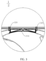
- an air-conditioner outdoor unit in one embodiment of the present invention comprises a control system (not shown), a fan 100, a deflector ring 200 sleeved outside the vane 110 of the fan 100, a vane stopping device 300, and a wind speed measuring device 400. Both the vane stopping device 300 and the wind speed measuring device 400 are connected to the control system.
- the vane stopping device is disposed on the deflector ring 200, and the vane stopping device is configured to prevent the vane 110 that is rotating from passively rotating.
- the wind speed measuring device 400 is disposed inside the outdoor unit and is used for detecting a wind speed value and a wind speed direction inside the outdoor unit.
- the control system is configured to control the vane stopping device 300 to start or shut down as well as a start-up frequency of the fan according to the wind speed detected by the wind speed measuring device 400.
- the air-conditioner outdoor unit above-mentioned is provided with the vane stopping device 300 on the deflector ring 200, and when the fan 100 in shut-down state is forced to rotate by the external airflow, a shutdown command can be executed to cause the fan 100 to stop rotating.
- the wind speed measuring device 400 can detect the magnitude and direction of the wind speed flowing through the vane 110, and according to the magnitude of the wind speed, a compensation operation on the actual operating frequency and the compensation size are set by the unit, thus greatly improving the start-up success rate of the fan 100, and ensuring the normal operation of an air-conditioner.
- the vane stopping device comprises an elastic sheet 310 and a driving member.
- a groove is disposed on an inner side of the deflector ring, and the elastic sheet 300 is movably disposed in the groove.
- the driving member is configured to drive the elastic sheet to abut against the vane to prevent the vane from passively rotating.
- the driving member comprises an electromagnetic conducting sheet 320.
- the electromagnetic conducting sheet 320 is fixedly disposed in the groove.
- the elastic sheet 310 and the electromagnetic conducting sheet 320 are configured to generate a repulsive force when being supplied with currents in the same direction, so as to push the elastic sheet 310 to abut against the vane 110 to prevent the vane 110 from passively rotating.
- the driving member may be configured as a mechanical drive structure, for example, a motor drives screws on two sides of the elastic sheet, and the screws push the elastic sheet 310, so that the projection in the middle of the elastic sheet 310 is generated to abut against the vane 110 for stopping. It is also possible that a screw driven by the motor directly pushes the middle of the elastic sheet to project to abut against the vane 110 for stopping.
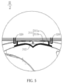
- the elastic sheet 310 comprises pushing portions 311 at two ends and a blocking portion 312 in the middle.
- the pushing portions 311 are movably disposed in the groove, and the pushing portions 311are slidable along the groove.
- Two electromagnetic conducting sheets 320 are provided, and these two electromagnetic conducting sheets 320 are respectively disposed outside the pushing portions 311.
- the pushing portion 311 comprises a magnetic conducting portion 311a and a guiding portion 311b connected with each other.
- the magnetic conducting portion 311a and the guiding portion 311b are disposed oppositely, and the guiding portion 311b is disposed in the groove.
- the magnetic conducting portion 311a and the electromagnetic conducting sheet 320 repel each other, so as to push the magnetic conducting portion 311a and the guiding portion 311b towards the middle.
- the pushing portions 311 are pushed by the repulsive force to approach to each other, so that the blocking portion 312 in the middle of the elastic sheet 310 is extruded to project towards the vane 110, and the projected blocking portion 312 can abut against the vane 110 to block the blade of the vane 110 when the vane 110 is rotating, thus causing the vane 110 to stop rotating.
- the magnetic conducting portion 311a and the electromagnetic conducting sheet 320 are supplied with currents in opposite direction, and an active force between the magnetic conducting portion 311a and the electromagnetic conducting sheet 320 is generated to restore the elastic sheet.
- the magnetic conducting portion 311a may also be a permanent magnet, and the electromagnetic conducting sheet 320 is configured to generate a repulsive force or an attractive force with the opposite magnetic conducting portion 311a when being supplied with power.
- the projected height of the blocking portion 312 may range from 15 to 20 mm.
- the blocking portion 312 may be configured as two hinged segments, and the connection part of the two segments projects when pushed at two ends.
- the blocking portion 312 may also be configured as an overall elastic sheet structure with elasticity.
- the wind speed measuring device 400 is preferably disposed close to the vane, and is disposed at the side of the vane close to the motor. As the wind speed measuring device 400 is disposed close to the vane, the wind speed causing the vane 110 to rotate can be measured relatively accurately.
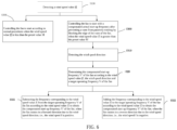
- control method for the fan of the air conditioner outdoor unit specifically comprises the following steps:
- the step of controlling the fan to start with a compensated start-up frequency comprises:
- the specific value of the preset value M is determined according to different vane structures. For vanes in different designs, different resistances are applied on vanes by the same wind speed, thereby values M being different.
- the wind speed measuring device keeps working, detects the wind speed f of the space where the outdoor unit is disposed, and transmits electronic signals converted from the wind speed to the master controller of the outdoor unit.
- a space airflow is blown to the inside from a side return air inlet of the outdoor unit, that is, the wind blows from the inside of the vane to the outside, the fan and an anemometer rotate in a forward direction, and the wind speed f is positive.
- the wind is blown in from an air outlet of the outdoor unit, that is, the wind blows from the outside of the vane to the inside, the fan and the anemometer rotate in a reverse direction, and the wind speed f is negative.
- the fan can start normally without any action from the system, but when it is detected that the wind speed value
- the foregoing control method for the fan controls the fan according to the detected wind speed through the vane stopping device and the wind speed measuring device.
- the wind speed value is greater than the preset value, compensation for the rotational speed of the fan is implemented, so as to greatly improve the start-up success rate of the fan, thereby ensuring the normal operation of an air-conditioner.
- the step of determining the compensated start-up frequency of the fan according to the wind speed value and the wind speed direction and a target operating frequency of the fan comprises:
- the compensable frequency F can be converted from the wind speed value
- the fan operates with a frequency consistent with the target operating frequency of the fan, thus ensuring normal start-up of the complete air-conditioner.
- the target operating frequency V of the fan needs to be50Hz, then it can be ensured that the system pressure is quickly balanced after the compressor starts. If at this time, it is detected that the fan is rotating in a forward direction, then the start-up frequency V' can be set as 45 Hz , which ensures that the target operating frequency V of the fan reaches 50 Hz after adding the driving force of the wind speed on the vane (equivalent to 5 Hz) ; and if it is detected that the fan is rotating in a reverse direction, the start-up frequency V' then can be set as 55Hz, which ensures that the target operating frequency V of the fan reaches 50 Hz after subtracting the resistance of the wind speed to the vane (equivalent to 5Hz).
Landscapes
- Engineering & Computer Science (AREA)
- Chemical & Material Sciences (AREA)
- Combustion & Propulsion (AREA)
- Mechanical Engineering (AREA)
- General Engineering & Computer Science (AREA)
- Physics & Mathematics (AREA)
- Fluid Mechanics (AREA)
- Air Conditioning Control Device (AREA)
- Control Of Positive-Displacement Air Blowers (AREA)
Claims (9)
- Eine Außeneinheit für eine Klimaanlage, bestehend aus:einem Gebläse (100);einem Ablenkring (200), der außerhalb einer Schaufel (110) des Gebläses (100) angebracht ist;eine Schaufelstoppvorrichtung (300) auf dem Ablenkring (200), die so konfiguriert ist, dass sie die Drehung der Schaufel (110), die sich passiv dreht, verhindert;eine Windgeschwindigkeitsmessvorrichtung (400) zum Erfassen der Windgeschwindigkeit des durch die Schaufel (110) strömenden Windes, wobei die Windgeschwindigkeit einen Windgeschwindigkeitswert und eine Windgeschwindigkeitsrichtung umfasst; undein Steuersystem, das mit der Schaufelstoppvorrichtung (300) und der Windgeschwindigkeitsmessvorrichtung (400) verbunden ist, um die Schaufelstoppvorrichtung (300) so zu steuern, dass sie entsprechend der Windgeschwindigkeit, die von der Windgeschwindigkeitsmessvorrichtung (400) erfasst wird, anläuft oder abgeschaltet wird, und um das Gebläse (100) so zu steuern, dass es mit einer kompensierten Anlauffrequenz anläuft, nachdem die Schaufel (110) durch die Schaufelstoppvorrichtung (300) daran gehindert wurde, sich passiv zu drehen, wenn der Windgeschwindigkeitswert größer als ein vorgegebener Wert ist;wobei die Schaufelstoppvorrichtung (300) ein elastisches Blech (310) und ein Antriebselement umfasst, eine Nut auf einer Innenseite des Ablenkrings (200) angeordnet ist, das elastische Blech (310) beweglich in der Nut angeordnet ist und das Antriebselement so konfiguriert ist, dass es das elastische Blech (310) so antreibt, dass es an der Schaufel (110) anliegt, um zu verhindern, dass sich die Schaufel (110) passiv dreht.
- Außeneinheit einer Klimaanlage nach Anspruch 1, wobei das Antriebselement ein elektromagnetisch leitendes Blech (320) umfasst, das fest in der Nut angeordnet ist, und das elastische Blech (310) und das elektromagnetisch leitende Blech (320) so konfiguriert sind, dass sie eine abstoßende Kraft erzeugen, wenn sie mit Strömen in der gleichen Richtung versorgt werden, um das elastische Blech (310) so zu schieben, dass es an der Schaufel (110) anliegt, um zu verhindern, dass sich die Schaufel (110) passiv dreht.
- Außeneinheit einer Klimaanlage nach Anspruch 2, wobei das elastische Blech (310) Druckabschnitte (311) an zwei Enden und einen Blockierabschnitt (312) in der Mitte umfasst; die Druckabschnitte (311) beweglich in der Nut angeordnet sind; zwei elektromagnetisch leitende Bleche (320) jeweils an den beiden Enden des elastischen Blechs (310) und gegenüber den Druckabschnitten (311) angeordnet sind; wenn das elastische Blech (310) und die elektromagnetisch leitenden Bleche (320) mit Strömen in der gleichen Richtung versorgt werden, werden die Druckabschnitte (311) an den beiden Enden durch die abstoßende Kraft gedrückt, um sich einander anzunähern, und der Blockierabschnitt (312) wird extrudiert, um in Richtung der Schaufel (110) vorzustehen, und der vorstehende Blockierabschnitt (312) stößt gegen die Schaufel (110) und bewirkt, dass die Schaufel (110) aufhört sich zu drehen.
- Außeneinheit einer Klimaanlage nach Anspruch 3, wobei die vorspringende Höhe des Blockierabschnitts (312) im Bereich von 15 bis 20 mm liegt.
- Außeneinheit einer Klimaanlage nach einem der Ansprüche 1 bis 4, wobei zwei Schaufelstoppvorrichtungen (300) symmetrisch auf dem Ablenkring (200) angeordnet sind.
- Steuerverfahren für ein Gebläse der Außeneinheit einer Klimaanlage nach Anspruch 1, das die folgenden Schritte umfasst:Erfassen eines Windgeschwindigkeitswerts;Steuern des Gebläses, um es zu starten, wenn der Windgeschwindigkeitswert kleiner als ein voreingestellter Wert ist; undSteuern des Gebläses, um es mit einer kompensierten Anlauffrequenz zu starten, nachdem verhindert wurde, dass sich eine Schaufel passiv dreht, indem der äußere Rand der Schaufel des Gebläses blockiert wird, wenn der Windgeschwindigkeitswert größer als der voreingestellte Wert ist.
- Steuerungsverfahren für ein Gebläse einer Außeneinheit einer Klimaanlage nach Anspruch 6, wobei der Schritt des Steuerns des Gebläses zum Starten mit einer kompensierten Anlauffrequenz umfasst:Erfassen einer Windgeschwindigkeitsrichtung, wenn der Windgeschwindigkeitswert größer als der voreingestellte Wert ist; undBestimmen der kompensierten Anlauffrequenz des Gebläses gemäß dem Windgeschwindigkeitswert, der Windgeschwindigkeitsrichtung und einer Sollbetriebsfrequenz des Gebläses.
- Steuerungsverfahren für ein Gebläse einer Außeneinheit einer Klimaanlage gemäß Anspruch 7, wobei der Schritt des Bestimmens der kompensierten tatsächlichen Anlauffrequenz des Gebläses gemäß dem Windgeschwindigkeitswert, der Windgeschwindigkeitsrichtung und einer Sollbetriebsfrequenz des Gebläses umfasst:Subtrahieren der Frequenz, die dem Windgeschwindigkeitswert entspricht, von der Sollbetriebsfrequenz des Gebläses gemäß dem Windgeschwindigkeitswert, um die kompensierte Anlauffrequenz des Gebläses zu erhalten, wenn sich das Gebläse aufgrund der Windgeschwindigkeitsrichtung in Vorwärtsrichtung dreht; undAddieren der Frequenz, die dem Windgeschwindigkeitswert entspricht, zur Sollbetriebsfrequenz des Gebläses entsprechend dem Windgeschwindigkeitswert, um die kompensierte Anlauffrequenz des Gebläses zu erhalten, wenn sich das Gebläse aufgrund der Windgeschwindigkeitsrichtung in umgekehrter Richtung dreht.
- Steuerungsverfahren für ein Gebläse einer Außeneinheit einer Klimaanlage nach einem der Ansprüche 6 bis 8, wobei der Schritt des Verhinderns der passiven Drehung der Schaufel durch Blockieren der Außenkante der Schaufel des Gebläses das Blockieren der Außenkante der Schaufel durch die Schaufelstoppvorrichtung umfasst, um die Schaufel an der passiven Drehung zu hindern.
Applications Claiming Priority (2)
| Application Number | Priority Date | Filing Date | Title |
|---|---|---|---|
| CN201710448171.4A CN107101285B (zh) | 2017-06-14 | 2017-06-14 | 空调室外机及空调室外机风机的控制方法 |
| PCT/CN2017/118102 WO2018227922A1 (zh) | 2017-06-14 | 2017-12-22 | 空调室外机及空调室外机风机的控制方法 |
Publications (3)
| Publication Number | Publication Date |
|---|---|
| EP3640552A1 EP3640552A1 (de) | 2020-04-22 |
| EP3640552A4 EP3640552A4 (de) | 2021-02-10 |
| EP3640552B1 true EP3640552B1 (de) | 2024-05-08 |
Family
ID=59659722
Family Applications (1)
| Application Number | Title | Priority Date | Filing Date |
|---|---|---|---|
| EP17913996.9A Active EP3640552B1 (de) | 2017-06-14 | 2017-12-22 | Klimaanlagenausseneinheit und steuerungsverfahren für einen lüfter einer klimaanlagenausseneinheit |
Country Status (5)
| Country | Link |
|---|---|
| US (1) | US11371723B2 (de) |
| EP (1) | EP3640552B1 (de) |
| CN (1) | CN107101285B (de) |
| ES (1) | ES2979282T3 (de) |
| WO (1) | WO2018227922A1 (de) |
Families Citing this family (8)
| Publication number | Priority date | Publication date | Assignee | Title |
|---|---|---|---|---|
| CN107101285B (zh) | 2017-06-14 | 2018-10-02 | 珠海格力电器股份有限公司 | 空调室外机及空调室外机风机的控制方法 |
| CN109114750A (zh) * | 2018-07-10 | 2019-01-01 | 青岛海尔空调器有限总公司 | 空调室外机的控制方法、装置及计算机可读存储介质 |
| CN111336584B (zh) * | 2020-03-13 | 2021-05-28 | 海信(广东)空调有限公司 | 一种空调器及室外风机启动控制方法 |
| US11699965B2 (en) * | 2020-10-20 | 2023-07-11 | Global Mixed-Mode Technology Inc. | Fan motor controller |
| CN113217994A (zh) * | 2021-05-10 | 2021-08-06 | 海信(山东)空调有限公司 | 双风道空调的出风控制方法和室内机 |
| CN115434934B (zh) * | 2022-09-30 | 2024-01-12 | 苏州浪潮智能科技有限公司 | 一种风扇阻转装置及风扇 |
| CN116294083B (zh) * | 2023-04-04 | 2025-09-12 | 珠海格力电器股份有限公司 | 室外风机控制方法和装置、室外机、空调及存储介质 |
| CN117006588A (zh) * | 2023-08-04 | 2023-11-07 | 珠海格力电器股份有限公司 | 一种空调外风机逆风启动控制装置及方法、空调 |
Citations (1)
| Publication number | Priority date | Publication date | Assignee | Title |
|---|---|---|---|---|
| CN106642572A (zh) * | 2016-12-19 | 2017-05-10 | 广东美的制冷设备有限公司 | 空调器控制方法、控制器及空调器 |
Family Cites Families (14)
| Publication number | Priority date | Publication date | Assignee | Title |
|---|---|---|---|---|
| JP2002235934A (ja) * | 2001-02-08 | 2002-08-23 | Hitachi Ltd | 空気調和機の室外機 |
| JP2004347209A (ja) * | 2003-05-21 | 2004-12-09 | Denso Corp | 室外ユニット及びそれを用いた空気調和機及びヒートポンプ式給湯機 |
| JP4252474B2 (ja) * | 2004-03-05 | 2009-04-08 | 三菱電機株式会社 | 空気調和機の室外機及び空気調和機の室外機のファングリル |
| CN1766448A (zh) * | 2004-10-27 | 2006-05-03 | 乐金电子(天津)电器有限公司 | 具有防止电机旋转轴逆转装置的室外机 |
| CN100461611C (zh) * | 2005-07-01 | 2009-02-11 | 国际整流器公司 | 启动无传感器马达的系统和方法 |
| JP5127612B2 (ja) * | 2007-08-02 | 2013-01-23 | 三菱電機株式会社 | モータ駆動制御装置並びに空気調和機、換気扇及びヒートポンプタイプの給湯機 |
| CN101839212B (zh) | 2009-03-17 | 2012-05-23 | 欧振玉 | 垂直轴风力发电装置 |
| CN101514687B (zh) | 2009-04-10 | 2011-07-20 | 重庆大学 | 一种兆瓦级风力发电机组的刹车系统及控制方法 |
| JP5424250B2 (ja) * | 2009-11-12 | 2014-02-26 | シャープ株式会社 | モータ制御装置 |
| WO2013132620A1 (ja) | 2012-03-07 | 2013-09-12 | 三菱電機株式会社 | 空気調和機 |
| CN105757825A (zh) | 2014-12-19 | 2016-07-13 | 珠海格力电器股份有限公司 | 空调机组及其室外机 |
| KR102436704B1 (ko) | 2015-03-23 | 2022-08-25 | 엘지전자 주식회사 | 팬 모터 구동장치 및 이를 구비하는 공기조화기 |
| CN105737275B (zh) * | 2016-02-19 | 2019-12-06 | 青岛海尔空调器有限总公司 | 风机组件和空调器 |
| CN107101285B (zh) | 2017-06-14 | 2018-10-02 | 珠海格力电器股份有限公司 | 空调室外机及空调室外机风机的控制方法 |
-
2017
- 2017-06-14 CN CN201710448171.4A patent/CN107101285B/zh active Active
- 2017-12-22 US US16/603,465 patent/US11371723B2/en active Active
- 2017-12-22 ES ES17913996T patent/ES2979282T3/es active Active
- 2017-12-22 WO PCT/CN2017/118102 patent/WO2018227922A1/zh not_active Ceased
- 2017-12-22 EP EP17913996.9A patent/EP3640552B1/de active Active
Patent Citations (1)
| Publication number | Priority date | Publication date | Assignee | Title |
|---|---|---|---|---|
| CN106642572A (zh) * | 2016-12-19 | 2017-05-10 | 广东美的制冷设备有限公司 | 空调器控制方法、控制器及空调器 |
Also Published As
| Publication number | Publication date |
|---|---|
| WO2018227922A1 (zh) | 2018-12-20 |
| CN107101285B (zh) | 2018-10-02 |
| CN107101285A (zh) | 2017-08-29 |
| US11371723B2 (en) | 2022-06-28 |
| US20210131679A1 (en) | 2021-05-06 |
| EP3640552A4 (de) | 2021-02-10 |
| EP3640552A1 (de) | 2020-04-22 |
| ES2979282T3 (es) | 2024-09-25 |
Similar Documents
| Publication | Publication Date | Title |
|---|---|---|
| EP3640552B1 (de) | Klimaanlagenausseneinheit und steuerungsverfahren für einen lüfter einer klimaanlagenausseneinheit | |
| CN105757876B (zh) | 一种空调导风板控制方法及装置 | |
| AU2012202762A1 (en) | Air volume adjustment device for air conditioner | |
| CN105591584B (zh) | 一种空调风机控制方法及装置 | |
| CN111637078A (zh) | 风机组件、空气处理装置、控制方法和可读存储介质 | |
| CN113864986B (zh) | 空调控制方法 | |
| KR20090041851A (ko) | 환기장치 | |
| CN105240987A (zh) | 一种空调器及其卸压控制电路和方法 | |
| JP2010523880A (ja) | 風力タービンにおける改良又は風力タービンに関する改良 | |
| CN110044008A (zh) | 空调室外机的控制方法 | |
| JP2018080905A (ja) | 温熱環境制御装置 | |
| CN104964497A (zh) | 一种空调及空调余热的利用方法 | |
| JP2679521B2 (ja) | 空気調和機及び空気調和機の風量制御装置 | |
| CN105627501A (zh) | 一种空调导风装置的控制方法及系统 | |
| KR101761376B1 (ko) | 전동 댐퍼 | |
| JP6255576B2 (ja) | 換気装置 | |
| JP6026149B2 (ja) | 給排気ファン制御システム | |
| CN211400225U (zh) | 一种空调除霜装置及其空调 | |
| CN105546681A (zh) | 一种防止冷却风扇逆转的装置、空调及方法 | |
| CN111306724A (zh) | 空调器及其控制方法与装置 | |
| CN110878989B (zh) | 用于空调器的防凝露控制方法 | |
| CN104930649A (zh) | 一种空调导风的监控方法及系统 | |
| JP5506096B2 (ja) | 送風装置 | |
| JP4710637B2 (ja) | ファン駆動装置及び空調機 | |
| CN211144862U (zh) | 一种结构优化的液压离心风机 |
Legal Events
| Date | Code | Title | Description |
|---|---|---|---|
| STAA | Information on the status of an ep patent application or granted ep patent |
Free format text: STATUS: THE INTERNATIONAL PUBLICATION HAS BEEN MADE |
|
| PUAI | Public reference made under article 153(3) epc to a published international application that has entered the european phase |
Free format text: ORIGINAL CODE: 0009012 |
|
| STAA | Information on the status of an ep patent application or granted ep patent |
Free format text: STATUS: REQUEST FOR EXAMINATION WAS MADE |
|
| 17P | Request for examination filed |
Effective date: 20191010 |
|
| AK | Designated contracting states |
Kind code of ref document: A1 Designated state(s): AL AT BE BG CH CY CZ DE DK EE ES FI FR GB GR HR HU IE IS IT LI LT LU LV MC MK MT NL NO PL PT RO RS SE SI SK SM TR |
|
| AX | Request for extension of the european patent |
Extension state: BA ME |
|
| DAV | Request for validation of the european patent (deleted) | ||
| DAX | Request for extension of the european patent (deleted) | ||
| A4 | Supplementary search report drawn up and despatched |
Effective date: 20210114 |
|
| RIC1 | Information provided on ipc code assigned before grant |
Ipc: F24F 1/38 20110101AFI20210107BHEP Ipc: F24F 110/30 20180101ALI20210107BHEP Ipc: F24F 1/46 20110101ALI20210107BHEP Ipc: F24F 11/77 20180101ALI20210107BHEP |
|
| P01 | Opt-out of the competence of the unified patent court (upc) registered |
Effective date: 20230530 |
|
| GRAP | Despatch of communication of intention to grant a patent |
Free format text: ORIGINAL CODE: EPIDOSNIGR1 |
|
| STAA | Information on the status of an ep patent application or granted ep patent |
Free format text: STATUS: GRANT OF PATENT IS INTENDED |
|
| INTG | Intention to grant announced |
Effective date: 20240201 |
|
| RAP3 | Party data changed (applicant data changed or rights of an application transferred) |
Owner name: GREE ELECTRIC APPLIANCES, INC. OF ZHUHAI Owner name: GREE ELECTRIC APPLIANCES (WUHAN) CO., LTD |
|
| GRAS | Grant fee paid |
Free format text: ORIGINAL CODE: EPIDOSNIGR3 |
|
| GRAA | (expected) grant |
Free format text: ORIGINAL CODE: 0009210 |
|
| STAA | Information on the status of an ep patent application or granted ep patent |
Free format text: STATUS: THE PATENT HAS BEEN GRANTED |
|
| AK | Designated contracting states |
Kind code of ref document: B1 Designated state(s): AL AT BE BG CH CY CZ DE DK EE ES FI FR GB GR HR HU IE IS IT LI LT LU LV MC MK MT NL NO PL PT RO RS SE SI SK SM TR |
|
| REG | Reference to a national code |
Ref country code: GB Ref legal event code: FG4D |
|
| REG | Reference to a national code |
Ref country code: CH Ref legal event code: EP |
|
| REG | Reference to a national code |
Ref country code: DE Ref legal event code: R096 Ref document number: 602017081855 Country of ref document: DE |
|
| REG | Reference to a national code |
Ref country code: IE Ref legal event code: FG4D |
|
| REG | Reference to a national code |
Ref country code: LT Ref legal event code: MG9D |
|
| REG | Reference to a national code |
Ref country code: NL Ref legal event code: MP Effective date: 20240508 |
|
| REG | Reference to a national code |
Ref country code: ES Ref legal event code: FG2A Ref document number: 2979282 Country of ref document: ES Kind code of ref document: T3 Effective date: 20240925 |
|
| PG25 | Lapsed in a contracting state [announced via postgrant information from national office to epo] |
Ref country code: IS Free format text: LAPSE BECAUSE OF FAILURE TO SUBMIT A TRANSLATION OF THE DESCRIPTION OR TO PAY THE FEE WITHIN THE PRESCRIBED TIME-LIMIT Effective date: 20240908 |
|
| PG25 | Lapsed in a contracting state [announced via postgrant information from national office to epo] |
Ref country code: BG Free format text: LAPSE BECAUSE OF FAILURE TO SUBMIT A TRANSLATION OF THE DESCRIPTION OR TO PAY THE FEE WITHIN THE PRESCRIBED TIME-LIMIT Effective date: 20240508 |
|
| PG25 | Lapsed in a contracting state [announced via postgrant information from national office to epo] |
Ref country code: HR Free format text: LAPSE BECAUSE OF FAILURE TO SUBMIT A TRANSLATION OF THE DESCRIPTION OR TO PAY THE FEE WITHIN THE PRESCRIBED TIME-LIMIT Effective date: 20240508 Ref country code: FI Free format text: LAPSE BECAUSE OF FAILURE TO SUBMIT A TRANSLATION OF THE DESCRIPTION OR TO PAY THE FEE WITHIN THE PRESCRIBED TIME-LIMIT Effective date: 20240508 |
|
| PG25 | Lapsed in a contracting state [announced via postgrant information from national office to epo] |
Ref country code: GR Free format text: LAPSE BECAUSE OF FAILURE TO SUBMIT A TRANSLATION OF THE DESCRIPTION OR TO PAY THE FEE WITHIN THE PRESCRIBED TIME-LIMIT Effective date: 20240809 |
|
| PG25 | Lapsed in a contracting state [announced via postgrant information from national office to epo] |
Ref country code: PT Free format text: LAPSE BECAUSE OF FAILURE TO SUBMIT A TRANSLATION OF THE DESCRIPTION OR TO PAY THE FEE WITHIN THE PRESCRIBED TIME-LIMIT Effective date: 20240909 |
|
| REG | Reference to a national code |
Ref country code: AT Ref legal event code: MK05 Ref document number: 1685281 Country of ref document: AT Kind code of ref document: T Effective date: 20240508 |
|
| PG25 | Lapsed in a contracting state [announced via postgrant information from national office to epo] |
Ref country code: NL Free format text: LAPSE BECAUSE OF FAILURE TO SUBMIT A TRANSLATION OF THE DESCRIPTION OR TO PAY THE FEE WITHIN THE PRESCRIBED TIME-LIMIT Effective date: 20240508 |
|
| PG25 | Lapsed in a contracting state [announced via postgrant information from national office to epo] |
Ref country code: AT Free format text: LAPSE BECAUSE OF FAILURE TO SUBMIT A TRANSLATION OF THE DESCRIPTION OR TO PAY THE FEE WITHIN THE PRESCRIBED TIME-LIMIT Effective date: 20240508 |
|
| PG25 | Lapsed in a contracting state [announced via postgrant information from national office to epo] |
Ref country code: PL Free format text: LAPSE BECAUSE OF FAILURE TO SUBMIT A TRANSLATION OF THE DESCRIPTION OR TO PAY THE FEE WITHIN THE PRESCRIBED TIME-LIMIT Effective date: 20240508 |
|
| PG25 | Lapsed in a contracting state [announced via postgrant information from national office to epo] |
Ref country code: LV Free format text: LAPSE BECAUSE OF FAILURE TO SUBMIT A TRANSLATION OF THE DESCRIPTION OR TO PAY THE FEE WITHIN THE PRESCRIBED TIME-LIMIT Effective date: 20240508 |
|
| PG25 | Lapsed in a contracting state [announced via postgrant information from national office to epo] |
Ref country code: PT Free format text: LAPSE BECAUSE OF FAILURE TO SUBMIT A TRANSLATION OF THE DESCRIPTION OR TO PAY THE FEE WITHIN THE PRESCRIBED TIME-LIMIT Effective date: 20240909 Ref country code: PL Free format text: LAPSE BECAUSE OF FAILURE TO SUBMIT A TRANSLATION OF THE DESCRIPTION OR TO PAY THE FEE WITHIN THE PRESCRIBED TIME-LIMIT Effective date: 20240508 Ref country code: NO Free format text: LAPSE BECAUSE OF FAILURE TO SUBMIT A TRANSLATION OF THE DESCRIPTION OR TO PAY THE FEE WITHIN THE PRESCRIBED TIME-LIMIT Effective date: 20240808 Ref country code: NL Free format text: LAPSE BECAUSE OF FAILURE TO SUBMIT A TRANSLATION OF THE DESCRIPTION OR TO PAY THE FEE WITHIN THE PRESCRIBED TIME-LIMIT Effective date: 20240508 Ref country code: LV Free format text: LAPSE BECAUSE OF FAILURE TO SUBMIT A TRANSLATION OF THE DESCRIPTION OR TO PAY THE FEE WITHIN THE PRESCRIBED TIME-LIMIT Effective date: 20240508 Ref country code: IS Free format text: LAPSE BECAUSE OF FAILURE TO SUBMIT A TRANSLATION OF THE DESCRIPTION OR TO PAY THE FEE WITHIN THE PRESCRIBED TIME-LIMIT Effective date: 20240908 Ref country code: HR Free format text: LAPSE BECAUSE OF FAILURE TO SUBMIT A TRANSLATION OF THE DESCRIPTION OR TO PAY THE FEE WITHIN THE PRESCRIBED TIME-LIMIT Effective date: 20240508 Ref country code: GR Free format text: LAPSE BECAUSE OF FAILURE TO SUBMIT A TRANSLATION OF THE DESCRIPTION OR TO PAY THE FEE WITHIN THE PRESCRIBED TIME-LIMIT Effective date: 20240809 Ref country code: FI Free format text: LAPSE BECAUSE OF FAILURE TO SUBMIT A TRANSLATION OF THE DESCRIPTION OR TO PAY THE FEE WITHIN THE PRESCRIBED TIME-LIMIT Effective date: 20240508 Ref country code: BG Free format text: LAPSE BECAUSE OF FAILURE TO SUBMIT A TRANSLATION OF THE DESCRIPTION OR TO PAY THE FEE WITHIN THE PRESCRIBED TIME-LIMIT Effective date: 20240508 Ref country code: AT Free format text: LAPSE BECAUSE OF FAILURE TO SUBMIT A TRANSLATION OF THE DESCRIPTION OR TO PAY THE FEE WITHIN THE PRESCRIBED TIME-LIMIT Effective date: 20240508 Ref country code: RS Free format text: LAPSE BECAUSE OF FAILURE TO SUBMIT A TRANSLATION OF THE DESCRIPTION OR TO PAY THE FEE WITHIN THE PRESCRIBED TIME-LIMIT Effective date: 20240808 |
|
| PG25 | Lapsed in a contracting state [announced via postgrant information from national office to epo] |
Ref country code: DK Free format text: LAPSE BECAUSE OF FAILURE TO SUBMIT A TRANSLATION OF THE DESCRIPTION OR TO PAY THE FEE WITHIN THE PRESCRIBED TIME-LIMIT Effective date: 20240508 |
|
| PG25 | Lapsed in a contracting state [announced via postgrant information from national office to epo] |
Ref country code: EE Free format text: LAPSE BECAUSE OF FAILURE TO SUBMIT A TRANSLATION OF THE DESCRIPTION OR TO PAY THE FEE WITHIN THE PRESCRIBED TIME-LIMIT Effective date: 20240508 |
|
| PG25 | Lapsed in a contracting state [announced via postgrant information from national office to epo] |
Ref country code: CZ Free format text: LAPSE BECAUSE OF FAILURE TO SUBMIT A TRANSLATION OF THE DESCRIPTION OR TO PAY THE FEE WITHIN THE PRESCRIBED TIME-LIMIT Effective date: 20240508 |
|
| PG25 | Lapsed in a contracting state [announced via postgrant information from national office to epo] |
Ref country code: SK Free format text: LAPSE BECAUSE OF FAILURE TO SUBMIT A TRANSLATION OF THE DESCRIPTION OR TO PAY THE FEE WITHIN THE PRESCRIBED TIME-LIMIT Effective date: 20240508 Ref country code: RO Free format text: LAPSE BECAUSE OF FAILURE TO SUBMIT A TRANSLATION OF THE DESCRIPTION OR TO PAY THE FEE WITHIN THE PRESCRIBED TIME-LIMIT Effective date: 20240508 |
|
| PG25 | Lapsed in a contracting state [announced via postgrant information from national office to epo] |
Ref country code: SM Free format text: LAPSE BECAUSE OF FAILURE TO SUBMIT A TRANSLATION OF THE DESCRIPTION OR TO PAY THE FEE WITHIN THE PRESCRIBED TIME-LIMIT Effective date: 20240508 |
|
| PG25 | Lapsed in a contracting state [announced via postgrant information from national office to epo] |
Ref country code: SM Free format text: LAPSE BECAUSE OF FAILURE TO SUBMIT A TRANSLATION OF THE DESCRIPTION OR TO PAY THE FEE WITHIN THE PRESCRIBED TIME-LIMIT Effective date: 20240508 Ref country code: SK Free format text: LAPSE BECAUSE OF FAILURE TO SUBMIT A TRANSLATION OF THE DESCRIPTION OR TO PAY THE FEE WITHIN THE PRESCRIBED TIME-LIMIT Effective date: 20240508 Ref country code: RO Free format text: LAPSE BECAUSE OF FAILURE TO SUBMIT A TRANSLATION OF THE DESCRIPTION OR TO PAY THE FEE WITHIN THE PRESCRIBED TIME-LIMIT Effective date: 20240508 Ref country code: EE Free format text: LAPSE BECAUSE OF FAILURE TO SUBMIT A TRANSLATION OF THE DESCRIPTION OR TO PAY THE FEE WITHIN THE PRESCRIBED TIME-LIMIT Effective date: 20240508 Ref country code: DK Free format text: LAPSE BECAUSE OF FAILURE TO SUBMIT A TRANSLATION OF THE DESCRIPTION OR TO PAY THE FEE WITHIN THE PRESCRIBED TIME-LIMIT Effective date: 20240508 Ref country code: CZ Free format text: LAPSE BECAUSE OF FAILURE TO SUBMIT A TRANSLATION OF THE DESCRIPTION OR TO PAY THE FEE WITHIN THE PRESCRIBED TIME-LIMIT Effective date: 20240508 |
|
| REG | Reference to a national code |
Ref country code: DE Ref legal event code: R097 Ref document number: 602017081855 Country of ref document: DE |
|
| PLBE | No opposition filed within time limit |
Free format text: ORIGINAL CODE: 0009261 |
|
| STAA | Information on the status of an ep patent application or granted ep patent |
Free format text: STATUS: NO OPPOSITION FILED WITHIN TIME LIMIT |
|
| 26N | No opposition filed |
Effective date: 20250211 |
|
| PG25 | Lapsed in a contracting state [announced via postgrant information from national office to epo] |
Ref country code: SI Free format text: LAPSE BECAUSE OF FAILURE TO SUBMIT A TRANSLATION OF THE DESCRIPTION OR TO PAY THE FEE WITHIN THE PRESCRIBED TIME-LIMIT Effective date: 20240508 |
|
| PG25 | Lapsed in a contracting state [announced via postgrant information from national office to epo] |
Ref country code: MC Free format text: LAPSE BECAUSE OF FAILURE TO SUBMIT A TRANSLATION OF THE DESCRIPTION OR TO PAY THE FEE WITHIN THE PRESCRIBED TIME-LIMIT Effective date: 20240508 |
|
| REG | Reference to a national code |
Ref country code: CH Ref legal event code: PL |
|
| PG25 | Lapsed in a contracting state [announced via postgrant information from national office to epo] |
Ref country code: LU Free format text: LAPSE BECAUSE OF NON-PAYMENT OF DUE FEES Effective date: 20241222 |
|
| PG25 | Lapsed in a contracting state [announced via postgrant information from national office to epo] |
Ref country code: SE Free format text: LAPSE BECAUSE OF FAILURE TO SUBMIT A TRANSLATION OF THE DESCRIPTION OR TO PAY THE FEE WITHIN THE PRESCRIBED TIME-LIMIT Effective date: 20240508 |
|
| REG | Reference to a national code |
Ref country code: BE Ref legal event code: MM Effective date: 20241231 |
|
| PG25 | Lapsed in a contracting state [announced via postgrant information from national office to epo] |
Ref country code: BE Free format text: LAPSE BECAUSE OF NON-PAYMENT OF DUE FEES Effective date: 20241231 |
|
| PG25 | Lapsed in a contracting state [announced via postgrant information from national office to epo] |
Ref country code: CH Free format text: LAPSE BECAUSE OF NON-PAYMENT OF DUE FEES Effective date: 20241231 |
|
| PG25 | Lapsed in a contracting state [announced via postgrant information from national office to epo] |
Ref country code: IE Free format text: LAPSE BECAUSE OF NON-PAYMENT OF DUE FEES Effective date: 20241222 |
|
| PGFP | Annual fee paid to national office [announced via postgrant information from national office to epo] |
Ref country code: GB Payment date: 20251111 Year of fee payment: 9 |
|
| PGFP | Annual fee paid to national office [announced via postgrant information from national office to epo] |
Ref country code: FR Payment date: 20251117 Year of fee payment: 9 |
|
| PGFP | Annual fee paid to national office [announced via postgrant information from national office to epo] |
Ref country code: ES Payment date: 20260119 Year of fee payment: 9 |
|
| PGFP | Annual fee paid to national office [announced via postgrant information from national office to epo] |
Ref country code: DE Payment date: 20251222 Year of fee payment: 9 |
|
| PGFP | Annual fee paid to national office [announced via postgrant information from national office to epo] |
Ref country code: IT Payment date: 20251231 Year of fee payment: 9 |