EP3639767B1 - Cutting accessory for use with a powered surgical handpiece - Google Patents
Cutting accessory for use with a powered surgical handpiece Download PDFInfo
- Publication number
- EP3639767B1 EP3639767B1 EP19214484.8A EP19214484A EP3639767B1 EP 3639767 B1 EP3639767 B1 EP 3639767B1 EP 19214484 A EP19214484 A EP 19214484A EP 3639767 B1 EP3639767 B1 EP 3639767B1
- Authority
- EP
- European Patent Office
- Prior art keywords
- shaft
- chuck
- bore
- collet
- accessory
- Prior art date
- Legal status (The legal status is an assumption and is not a legal conclusion. Google has not performed a legal analysis and makes no representation as to the accuracy of the status listed.)
- Active
Links
Images


Classifications
-
- A—HUMAN NECESSITIES
- A61—MEDICAL OR VETERINARY SCIENCE; HYGIENE
- A61B—DIAGNOSIS; SURGERY; IDENTIFICATION
- A61B17/00—Surgical instruments, devices or methods
- A61B17/16—Instruments for performing osteoclasis; Drills or chisels for bones; Trepans
- A61B17/1613—Component parts
- A61B17/162—Chucks or tool parts which are to be held in a chuck
-
- A—HUMAN NECESSITIES
- A61—MEDICAL OR VETERINARY SCIENCE; HYGIENE
- A61B—DIAGNOSIS; SURGERY; IDENTIFICATION
- A61B17/00—Surgical instruments, devices or methods
- A61B17/16—Instruments for performing osteoclasis; Drills or chisels for bones; Trepans
- A61B17/1613—Component parts
- A61B17/1615—Drill bits, i.e. rotating tools extending from a handpiece to contact the worked material
-
- A—HUMAN NECESSITIES
- A61—MEDICAL OR VETERINARY SCIENCE; HYGIENE
- A61B—DIAGNOSIS; SURGERY; IDENTIFICATION
- A61B17/00—Surgical instruments, devices or methods
- A61B17/16—Instruments for performing osteoclasis; Drills or chisels for bones; Trepans
- A61B17/1613—Component parts
- A61B17/1622—Drill handpieces
-
- A—HUMAN NECESSITIES
- A61—MEDICAL OR VETERINARY SCIENCE; HYGIENE
- A61B—DIAGNOSIS; SURGERY; IDENTIFICATION
- A61B17/00—Surgical instruments, devices or methods
- A61B17/16—Instruments for performing osteoclasis; Drills or chisels for bones; Trepans
- A61B17/1613—Component parts
- A61B17/1628—Motors; Power supplies
-
- A—HUMAN NECESSITIES
- A61—MEDICAL OR VETERINARY SCIENCE; HYGIENE
- A61B—DIAGNOSIS; SURGERY; IDENTIFICATION
- A61B17/00—Surgical instruments, devices or methods
- A61B17/16—Instruments for performing osteoclasis; Drills or chisels for bones; Trepans
- A61B17/1613—Component parts
- A61B17/1631—Special drive shafts, e.g. flexible shafts
-
- A—HUMAN NECESSITIES
- A61—MEDICAL OR VETERINARY SCIENCE; HYGIENE
- A61B—DIAGNOSIS; SURGERY; IDENTIFICATION
- A61B17/00—Surgical instruments, devices or methods
- A61B2017/00477—Coupling
Definitions
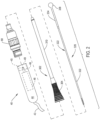
- the powered surgical tool In modern surgery, one of the most important instruments available to medical personnel is the powered surgical tool.
- this tool includes a handpiece in which a motor is housed. Secured to the handpiece is a cutting accessory.
- the cutting accessory is designed for application to a surgical site on a patient to accomplish a specific medical task.
- Some powered surgical tools are provided with drills or burs for cutting bores into hard tissue or for selectively removing the hard and soft tissue.
- Still other powered surgical tools are provided with saw blades as cutting accessories. These tools are used for separating large sections of hard and/or soft tissue.
- the ability to use powered surgical tools on a patient has lessened the physical strain of physicians and other medical personnel when performing procedures on a patient. Moreover, most surgical procedures can be performed more quickly, and more accurately, with powered surgical tools than with the manual equivalents that preceded them.
- the practitioner may selectively set the extent to which the accessory shaft extends forward of the handpiece.
- the practitioner may want to set the distal end of the accessory shaft, the end to which the tissue working member is attached, to extend a relatively short distance forward of the handpiece the shaft.
- the accessory is so set by positioning the accessory shaft so the distally located retention features are engaged by the collet feet.
- the practitioner can reposition the cutting accessory so that the tissue working member is located a relatively long distance away from the handpiece.
- the shaft if longitudinally set relative to the collet so the proximally located retention features are the retention features against which the collet feet engage.
- An advantage of the above construction is that a single cutting accessory can be positioned so that accessory head is located different distances from the handpiece. This eliminates the need to provide plural cutting accessories constructed so that the only distance between two different accessories is the overall length of the accessory shaft.
- the accessory shaft For the accessory shaft to bend or flex or to fit within a small diameter attachment, the accessory shaft is typically designed to be relatively small in diameter.
- the flexible section of some accessory shafts have a diameter of 2 mm or less.
- the undesirable rotation of the accessory shaft can occur during the procedure when the handpiece is actuated. Specifically, when the handpiece is rotated, the whole of the accessory shaft is supposed to rotate at the same speed. However, owing to imposition of different forces on the different portions of the accessory and the flexible nature of the accessory shaft, there may some twist in the accessory shaft around the longitudinal axis of the shaft. As a result of this twist, and the natural tendency of the material forming the shaft to twist back to the untwisted state, the proximal end of the accessory shaft, the end of the shaft disposed in the drive shaft integral with the handpiece may want to rotate within the drive shaft. This rotation of the shaft can result in the shaft retention features rotating out of engagement with the collet feet or other chuck retention features that hold the shaft in position. If this type of accessory shaft-relative to-drive shaft movement occurs, the accessory shaft may not be firmly held in place to the drive shaft.
- a chuck of a powered surgical handpiece for holding the cutting accessory to the handpiece is defined in claim 7.
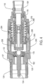
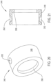
- Chuck 60 is formed to have a shell 62 and a cap 104, seen in Figures 3-5 , that collectively form the body of housing of the chuck.
- Shell 62 seen best in Figures 6-8 , is formed from a single piece of metal that generally has a number of different cylindrical sections.
- One proximal cylindrical section is a foot 64.
- Foot 64 is formed with two indentations that extends inwardly from the outer surface of the foot and circumferentially around the foot. A first one of these indentations is annular recess 66.
- the second indentation is a groove 68. In cross section, both recess 66 and groove 68 are rectangular in shape.
- the shell 62 is formed so that groove 68 is spaced forward from recess 66 and is shorter in length than the recess.
- a bore 69 partially seen in Figure 5 , extends laterally inwardly from the outer surface of foot. Bore 69 is located distally forward of groove 68.
- the shell 62 Forward of the foot 64, the shell 62 has a collar 70.
- Collar 70 has an outer diameter larger than the outer diameter of foot 64. In the depicted version of the invention, the outer diameter of collar 70 is tapered. Extending distally from the proximal end of the collar 70 the diameter of the collar slightly decreases.
- a bore 92 extends distally forward from the distal end of bore 88.
- Shell 62 is formed so that bore 92 is located within the shell collar 70. Bore 92 has a diameter less than that of bore 88. The distal end of bore 92 opens into a bore 96. Bore 96 has a diameter less than that bore 88 and greater than that of bore 96.
- the shell 62 is further formed so as to define a groove 94 in the inner wall of the shell that defines bore 96. Groove 94 extends outwardly from the proximal end of bore 96 where bore 88 opens into bore 96. Groove 94 extends circumferentially around the outside of bore 96.
- a bore 162 extends proximally rearward from the distal end shaft head 158. Bore 162 extends through the shaft head 158 and neck 150 and partially through the torso 142. The proximal end of bore 162 opens into a bore 166. Bore 166 is coaxial with and smaller in diameter than bore 162. A step 164 at the proximal end of bore 162 defines the transition between bore 162 and bore 166. Bore 166 terminates at a location forward of the proximal end of the shaft torso 142. Torso openings 146 open into bore 166.
- Two bearing assemblies 170 rotatably hold the drive shaft 134 to the chuck housing.
- the inner and outer races of the bearing assemblies 170 are the inner and outer races of the bearing assemblies 170.
- the inner race of the proximal located bearing assembly 170 is disposed over waist section 139 of the drive shaft 134.
- the outer race of the proximal located bearing assembly 170 is seated against the inner wall of shell 62 that defines bore 96.
- a wave washer 172 ( Figure 5 ) is located immediately proximal to the proximal end of proximal bear assembly 170.
- the outer perimeter of the wave washer 172 is seated in shell groove 94.
- the inner perimeter of the wave washer is seated in drive shaft groove 140. Wave washer 172 bears against the drive shaft 134 so as to urge the drive shaft distally forward.
- the inner race of the distal bearing assembly 170 is seated around the drive shaft head 158.
- the outer surface of the bearing assembly is disposed against the inner cylindrical wall of the cap 106 that defines bore 111.
- the components forming 1chuck 60 are dimensioned so that distal end of the drive shaft is spaced rearward of undercut 113 internal to cap 106.
- Each ankle 194 and a foot 196 are located at the distal end of each leg 192.
- Each ankle 194 has an outer surface that is flush with the outer surface of the leg from which the foot extends.
- the feet 196 have outer surfaces that extend radially outwardly from the outer surface of the ankles 194.
- Each ankle 194 and foot 196 has a pair of opposed sides 198.
- the ankle 194 and foot 196 are shaped so that the sides 198 taper relative to a proximal to distal longitudinal axis through the ankle and foot.
- the distance between opposed sides 198 is relatively short, less than the distance across the leg. Extending distally, the distance between sides 198 of a single foot 196 increases.
- collet 178 When chuck 60 is assembled, the base and legs of collet 178 are seated in drive shaft bore 166. Collet ankles 194 and feet 196 are disposed in collar notch 229. Also disposed in collet bore 162 is alignment collar 212. Each collet ankle 194 and associated foot 196 is disposed in an end of alignment collar notch 229 as seen in Figures 15 and 15A . Collet 178 and alignment collar 212 are, as seen best in Figure 15A , are further formed so that when the collet and ankles 194 and feet 196 are seated in the collar notch 229, the ankles and feet are spaced away from the adjacent notch-defining surfaces. There is a narrow separation between the collet side surfaces 198 and the adjacent surfaces of the alignment collar 212.
- collet feet 196 There is wider gap between the distal end surfaces of the collet feet 196 and the adjacent surfaces of the alignment collar.
- the depicted gaps are enlarged for purposes of illustration. It should be understood that collet feet 196 are able to flex laterally relative to the alignment collar feet 226.
- Lock ring 240 is further formed so that two grooves 244 extend inwardly from and longitudinally along the inner wall of the ring. Grooves 244 are symmetric with respect to the proximal-to-distal longitudinal axis through the ring 240. In cross-section, in planes perpendicular to the longitudinal axis through the lock ring, grooves 244 are curved in shape.
- An actuator 246, seen best in Figures 20 and 21 is a second component that is part of the assembly that longitudinally translates the collet 178 and alignment collar 212.
- the actuator 246 has a sleeve like main body 248.
- the outer diameter of the actuator main body 248 is dimensioned to allow the actuator to engage in close longitudinal slip fit movement within shell bore 98.
- actuator 246 has a lip 250 that extends radially inwardly from the main body.
- the actuator 246 is further dimensioned so the inner diameter of lip is approximately 2.5 mm greater than the outer diameter of the drive shaft torso 142.
- Actuator 246 also has two symmetrically opposed divots 252.
- Each divot 252 is a void space in the form of a slice section of sphere.
- Each divot 252 is shown opening into the interior of the actuator 246. This opening is present for manufacturing reasons.
- a drive link 258, seen best in Figure 22 is also slidably disposed in the shell bore 98.
- the drive link 258 has a tube like main body 260.
- the outer surface of main body 260 has a diameter less than the inner diameter of actuator lip 250.
- the inner surface of the main body 260 has a diameter sufficiently greater than that of the drive shaft torso 142 that the drive link can freely move longitudinally over the drive shaft 134.
- Drive link 258 has a rim 262 that extends radially outwardly from the main body 260. Rim 262 is located at the distal end of the main body 260.
- the drive link 258 is further formed to have two coaxial bores 264. Bores 264 are located forward of the proximal end of the body. The common axis around which bores 264 is centered intersects the proximal-to-distal longitudinal axis through the drive link 258.
- the drive link 258 is disposed over drive shaft torso 142 to move over the torso.
- Drive link 258 is positioned so that drive link rim 262 is located immediately distally forward of the actuator lip 250.
- the components forming the chuck are dimensioned so that the drive link rim 262 projects over the actuator lip 250.
- Two coil springs 268 and 270 are disposed around the drive shaft torso 142.
- a first spring, spring 268, is in terms of radial distance, is located closest to the outer cylindrical surface of the torso 142.
- the proximal end of spring 268 abuts the rim 262 of drive link 258.
- the distal end of spring 268 abuts the annular proximal facing surface 152 of the drive shaft neck 150.
- Spring 268 is in compression. Spring 268 thus normally exerts a force that holds the drive link 258 proximally away from the drive shaft neck 150.
- the force exerted by spring 268 can be overcome by the manual force that causes the longitudinal translation of the drive link.
- Spring 270 is located outwardly of and surrounds spring 268. The proximal end of spring 270 is disposed against the ring shaped, distally directed surface of the actuator 246. The opposed distal end of the spring 270 is disposed against the ring shaped step internal to the cap 104 that is the transition between bores 107 and 109.
- stop ring 274 seen in Figure 23 .
- stop ring 274 is ring shaped.
- the stop ring 274 is formed with a number of sections with flat outer faces 276.
- One outer face 276 is formed with an opening 278 that extends through the ring towards the center of the ring 274.
- Stop ring 274 is further formed so as to have a closed end bore 280 that extends proximally from the distally proximally directed face of the ring.
- Stop ring 274 is fixedly disposed in chuck 60 over the portion of shell head 72 forward of recess 78.
- a pin 282 ( Figure 5 ) that extends through lock ring opening 278 into shell bore 80 holds the stop ring fast to the shell 62.
- a coil spring 284, seen in Figures 4 and 5 is located immediately proximal to stop ring 274.
- Spring 284 has two opposed legs (not identified). A first leg extends proximally and is disposed in bore formed in the lock ring 240 (bore not seen). The second leg extends distally and extends into stop ring bore 280.
- Spring 284 places a force of lock ring 240 that opposes the rotation of the lock ring. The force spring 284 place on the lock ring 240 can be overcome by the finger force applied to the lock ring 240 to rotate the lock ring.
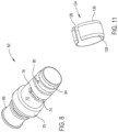
- the nose 302 includes a base 304.
- Base 304 is generally tapered in shape in that, extending from the proximal end the outer surface, the diameter of the base decreases. There are portions 304 of the base that are of constant diameter.
- the inside of the base 304 has a void 306 and coupling features 308. Void 306 and coupling features 308 are designed to facilitate the releasable coupling of nose base 304 over cap head 116 and neck 112. The specific means by which the nose is coupled to chuck 60 are not part of the present invention. Accordingly, void 306 and coupling features 308 are not further described.
- a constant diameter tube 310 is mounted to and extends distally forward of nose base 302.
- the distal end of the lumen 312 internal to the tube opens into base void 304.
- Bearing assemblies 314 rotatably hold the shaft 322 integral with cutting accessory in the tube lumen 312.
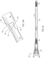
- a cutting accessory 320 includes an elongated shaft 322.
- a tissue working member 338 is attached to the distal end of the shaft 322.
- the tissue working member is designed to accomplish a procedure on the living tissue against which the tissue working member is applied.
- the depicted tissue working 338 member is a bur. (Cutting flutes of the bur not illustrated.)
- the specific structure of the tissue working member 338 is not part of the present invention.
- the tissue working member may be a bur with a head that has a shape that is not spherical.
- the tissue working member may be a drill bit. It
- Accessory shaft 322 is generally in the form of a cylindrical rod.
- shaft 32 is formed out of M42 tool steel or 440A stainless steel.
- shaft 322 Adjacent the tissue working member 338, shaft 322 has a distal section 334 that is relatively inflexible.
- Shaft distal section 334 has a length between 1 and 3 cm.
- shaft 322 Proximal to distal section 334, shaft 322 has a proximal section 332.
- Shaft proximal section 332 is smaller in diameter than shaft distal section 330. This reduced diameter of the proximal section 332 allows the proximal section to, when inserted in a curved or angled nose tube flex.
- Shaft proximal section 332 has a diameter of 2 mm or less and often a diameter of 1.6 mm or less.
- the accessory shaft 322 is further formed so that there is a taper 323 at the most proximal end of the shaft. Thus, extending distally from the most proximal end of the shaft 322, the diameter of the shaft increases.
- Shaft 322 is further formed two have on diametrically opposed sides of the shaft, plural faces 324. Faces 324 are arranged longitudinally along the shaft and extend forward from the tapered sections of the shaft. In the illustrated version of the invention each face is concave. Each face 324 is arcuate in shape and curves inwardly from the outer cylindrical surface of the shaft proximal section 332. At the most proximal end there are not two full faces.
- Each face 324 at the proximal end, extending distally from that end curves outwardly towards the adjacent distally located face.
- crest 326 one identified in each of Figures 25 and 27 . Crests 326 appear as lines.
- each flat 328 is rectangularly shaped and recessed relative to the outer cylindrical surface of the shaft.
- Flats 328 are planner. The planes in which flats 328 lie are parallel to the longitudinal axis through shaft 322.
- Each flat 328 is located a distance away from the longitudinal axis of the shaft equal to the distance the crests are spaced from the shaft.
- a step 329 defines the transition of each flat 328 from the adjacent distally extending portion of the shaft proximal section 332. Steps 329 are in a plane that is generally perpendicular to the longitudinal axis through the shaft 322.
- the components forming system 40 are shaped so that the radius of curvature of shaft 322 is typically between 0.01 and 0.02 mm less than the radius of the circle defined by the curved sides of alignment collar bore 236.
- the radius of curvature of the shaft is further understood to be approximately 0.2 to 0.4 mm less than the radius around the center of void 193 internal to the collet 178.
- the distance across the shaft flats 328 is 0.02 and 0.05 mm less than the distance across the parallel sides of collar bore 236.
- Shaft faces 324 are shaped so that each face can receive the outwardly curved face of one of the collet toe surfaces 211.
- System 40 of this invention is prepared for use by first connecting chuck 60 to handpiece 42. The results in the coupling of the chuck drive shaft 134 to the handpiece spindle 48. Nose 302 is fitted over the chuck cap 104.
- the lock ring 240 is rotated to place the chuck in the load state. More particularly the lock ring 240 is rotated to cause the distal translational movement of actuator 246.
- the movement of the actuator lip 250 against rim 262 of the drive link 258 results in the like distal movement of the drive link.
- the distal translation of the drive link 258 results in the like distal movement of collet 178 such that that collet feet 196 are located forward of drive shaft step 164. When the collet 178 is so positioned, the collet feet 196 are free to flex outwardly.
- System 40 is in the load state.
- the system 30 is in condition to receive the cutting accessory 320.
- the proximal end of the cutting accessory is inserted into the nose 302 and into the chuck.
- the accessory may not be aligned with collar bore 236.
- the proximal end of the accessory shaft 322 strikes the frustro-conically shaped surface of the alignment collar 212 that defines the collar opening 232. Owing to the presence of the taper of the surface of the collar that defines openings 232 and taper 323 of the shaft, the continued insertion of the accessory shaft 322 results in the lateral translation of the proximal end of the accessory toward bore 234.
- the shaft When the proximal end of the shaft enters collar bore 234, the shaft may not be aligned with the adjacent accessory bore 236.
- the accessory crests 326 should lie in planes parallel to the planes of the parallel sides of bore 236. In these components are not so aligned, the further advancement of the accessory is stopped by the abutment of the accessory around the step internal to the collar between bores 234 and 236. This blocking of the accessory advancement functions as a tactile cue to the individual performing this process that the accessory 320 needs to be aligned with the chuck 60.
- This alignment is easily performed by rotating the shaft so the shaft is able to pass through the collar bore 236. Since the proximal end of the shaft is seated in bore 234 there is little likelihood that, as a result of this rotation of the shaft, the shaft will work itself out of bore 234.
- Cutting accessory 320 is inserted in the chuck 60 until the tissue working member 338 is located forward the distal end of the nose 302 the distance desired by the practitioner. At this time, the collet toe surfaces 211 abut the opposed pair of shaft faces 324.
- the shaft is locked into position by rotating the lock ring 240 in the direction opposite the direction the ring is rotated to place the chuck in the load state. This opposed rotation of the ring 240 causes the ring to translate the actuator 246 proximally.
- Spring 268 is then freed to push the drive link 258 proximally. The proximal displacement of the drive link 258 causes a like proximal movement in the collet 178.
- collet 178 is displaced proximally until collet surfaces 206 abut step 164 internal to the drive shaft.
- This component against component abutment causes an inward movement of the collet feet 196 against the adjacent faces 196 of the cutting accessory 302.
- Chuck 60 is thus in the locked or run state.
- cable 43 is connected to the console that provides power to handpiece motor 46.
- System 40 is used by activating motor 46.
- the rotational moment of the handpiece drive spindle 48 is transferred to chuck drive shaft 134.
- Pin 266 transfers this rotational movement to the collet 178. Since the accessory shaft 320 is clamped between the collet feet 196, the accessory 320 undergoes a like rotation.
- the rotating tissue working member 332 is pressed against tissue in order to perform the desired surgical procedure.
- the components forming system 40 of this invention are thus designed to facilitate the easy coupling of the accessory 320 to the other components of the system. If the accessory shaft 322 is not aligned with the collet feet 198, the shape of the shaft and the alignment collar compel that, to further insert the shaft into the chuck, the shaft be rotated until the components are in alignment. The shape of these components lead the person setting up the system for use to so rotate the accessory shaft 322.
- the components of this invention are configured so that the accessory can be set so the distance the tissue working member 338 is set forward of the distal end of the nose 302 can be selectively set. This eliminates the need to provide plural different tissue working members the only difference between them being shafts of marginally different lengths.
- the shaft is disposed in the chuck so that shaft flats 328 are seated in the alignment collar bore 236. Further, should the person assembling the system 40 for use attempt to over insert the shaft in the collet, the steps 329 immediately forward of shaft flats 328 abut the alignment collar steps 235 around bore 236. This step-against-step abutment prevents insertion of the shaft beyond the useful depth of the shaft in the chuck 60.
- Nose tube 310 typically has a diameter of 0.3 cm or less and often 0.15 cm or less.
- the accessory shaft has a relatively small diameter so as to facilitate the insertion and flexing of the shaft in a nose with a curved tube 310.
- system 40 of this invention is designed to perform minimally invasive surgical (MIS) procedures.
- MIS minimally invasive surgical
- the handpiece may have a transmission between the motor and the chuck drive shaft.
- One such transmission is present the transmission typically steps down the speed of the rotational moment so the chuck drive shaft rotates at a speed less than the speed of the rotor internal to the motor.
- each flat 324 may not be aligned with a row of retention features 324.
- the corresponding alignment collar face may not be aligned with one of the chuck clamping members.
- the alignment collar may not always be a separate component from the other components of the chuck.
- the alignment collar may be formed integral with the drive shaft.
- the alignment collar thus defines a non-circular opening that leads to void internal to the drive shaft in which the accessory shaft is disposed and into which the locking balls move in and out.
Landscapes
- Health & Medical Sciences (AREA)
- Surgery (AREA)
- Life Sciences & Earth Sciences (AREA)
- Biomedical Technology (AREA)
- Medical Informatics (AREA)
- Orthopedic Medicine & Surgery (AREA)
- Oral & Maxillofacial Surgery (AREA)
- Engineering & Computer Science (AREA)
- Dentistry (AREA)
- Heart & Thoracic Surgery (AREA)
- Nuclear Medicine, Radiotherapy & Molecular Imaging (AREA)
- Molecular Biology (AREA)
- Animal Behavior & Ethology (AREA)
- General Health & Medical Sciences (AREA)
- Public Health (AREA)
- Veterinary Medicine (AREA)
- Surgical Instruments (AREA)
- Dental Tools And Instruments Or Auxiliary Dental Instruments (AREA)
Priority Applications (1)
| Application Number | Priority Date | Filing Date | Title |
|---|---|---|---|
| EP24184232.7A EP4413934A3 (en) | 2014-08-06 | 2015-07-27 | Cutting accessory for use with a powered surgical handpiece |
Applications Claiming Priority (3)
| Application Number | Priority Date | Filing Date | Title |
|---|---|---|---|
| US201462033870P | 2014-08-06 | 2014-08-06 | |
| PCT/US2015/042221 WO2016022317A1 (en) | 2014-08-06 | 2015-07-27 | Powered surgical handpiece with a chuck that facilitates alignment of the cutting accessory fitted to the tool |
| EP15747338.0A EP3177215B1 (en) | 2014-08-06 | 2015-07-27 | Powered surgical handpiece with a chuck that facilitates alignment of the cutting accessory fitted to the tool |
Related Parent Applications (1)
| Application Number | Title | Priority Date | Filing Date |
|---|---|---|---|
| EP15747338.0A Division EP3177215B1 (en) | 2014-08-06 | 2015-07-27 | Powered surgical handpiece with a chuck that facilitates alignment of the cutting accessory fitted to the tool |
Related Child Applications (1)
| Application Number | Title | Priority Date | Filing Date |
|---|---|---|---|
| EP24184232.7A Division EP4413934A3 (en) | 2014-08-06 | 2015-07-27 | Cutting accessory for use with a powered surgical handpiece |
Publications (2)
| Publication Number | Publication Date |
|---|---|
| EP3639767A1 EP3639767A1 (en) | 2020-04-22 |
| EP3639767B1 true EP3639767B1 (en) | 2024-07-03 |
Family
ID=53783398
Family Applications (3)
| Application Number | Title | Priority Date | Filing Date |
|---|---|---|---|
| EP19214484.8A Active EP3639767B1 (en) | 2014-08-06 | 2015-07-27 | Cutting accessory for use with a powered surgical handpiece |
| EP15747338.0A Active EP3177215B1 (en) | 2014-08-06 | 2015-07-27 | Powered surgical handpiece with a chuck that facilitates alignment of the cutting accessory fitted to the tool |
| EP24184232.7A Pending EP4413934A3 (en) | 2014-08-06 | 2015-07-27 | Cutting accessory for use with a powered surgical handpiece |
Family Applications After (2)
| Application Number | Title | Priority Date | Filing Date |
|---|---|---|---|
| EP15747338.0A Active EP3177215B1 (en) | 2014-08-06 | 2015-07-27 | Powered surgical handpiece with a chuck that facilitates alignment of the cutting accessory fitted to the tool |
| EP24184232.7A Pending EP4413934A3 (en) | 2014-08-06 | 2015-07-27 | Cutting accessory for use with a powered surgical handpiece |
Country Status (7)
| Country | Link |
|---|---|
| US (3) | US10736642B2 (enExample) |
| EP (3) | EP3639767B1 (enExample) |
| JP (2) | JP6647279B2 (enExample) |
| CN (3) | CN111227901B (enExample) |
| AU (3) | AU2015298611B2 (enExample) |
| CA (2) | CA3208370A1 (enExample) |
| WO (1) | WO2016022317A1 (enExample) |
Families Citing this family (14)
| Publication number | Priority date | Publication date | Assignee | Title |
|---|---|---|---|---|
| US7686809B2 (en) * | 2006-09-25 | 2010-03-30 | Stryker Spine | Rod inserter and rod with reduced diameter end |
| WO2016022317A1 (en) | 2014-08-06 | 2016-02-11 | Stryker Corporation | Powered surgical handpiece with a chuck that facilitates alignment of the cutting accessory fitted to the tool |
| CA3073178A1 (en) * | 2017-08-17 | 2019-02-21 | Stryker Corporation | Surgical handpiece for measuring depth of bore holes and related accessories |
| DE102017010033A1 (de) * | 2017-10-27 | 2019-05-02 | Joimax Gmbh | Medizinische Vorrichtung |
| AU2019215215B2 (en) * | 2018-02-05 | 2024-12-19 | Stryker European Operations Holdings Llc | Apparatus and method for securing an elongate member to a medical instrument |
| CN110638500B (zh) * | 2019-02-27 | 2021-04-20 | 中国科学院深圳先进技术研究院 | 一种夹持机构及脊柱椎板磨削手术装置 |
| CN114007529B (zh) * | 2019-06-06 | 2024-09-27 | 史赛克欧洲运营有限公司 | 旋转外科切削工具及相关附件 |
| KR102629508B1 (ko) * | 2020-12-16 | 2024-01-25 | 재단법인 대구경북첨단의료산업진흥재단 | 수술용 쉐이버 샤프트 및 이를 포함하는 수술용 쉐이버 |
| WO2022131813A1 (ko) * | 2020-12-16 | 2022-06-23 | 재단법인 대구경북첨단의료산업진흥재단 | 수술용 쉐이버 샤프트 및 이를 포함하는 수술용 쉐이버 |
| US11871951B2 (en) | 2021-06-25 | 2024-01-16 | Arthrex, Inc. | Surgical tool seal |
| US12025188B1 (en) * | 2021-10-01 | 2024-07-02 | Agility Robotics, Inc. | Actuator encoder assembly method and apparatus |
| US20230397916A1 (en) * | 2022-06-13 | 2023-12-14 | Stryker Corporation | Surgical Attachments for a Surgical Handpiece System |
| US20250057542A1 (en) * | 2023-08-17 | 2025-02-20 | Medtronic Ps Medical, Inc. | Collar lock and method for locking a shaft within a housing |
| CN119632624A (zh) * | 2023-09-15 | 2025-03-18 | 北京歌锐科技有限公司 | 一种用于椎体成形术的动力驱动通道器 |
Family Cites Families (45)
| Publication number | Priority date | Publication date | Assignee | Title |
|---|---|---|---|---|
| US3507508A (en) * | 1968-07-24 | 1970-04-21 | Edward N Andrews | Toolholder bushing |
| DE2354168C2 (de) * | 1973-10-30 | 1984-10-04 | Robert Bosch Gmbh, 7000 Stuttgart | Werkzeughalter für einen Bohrhammer |
| US4255145A (en) * | 1978-03-16 | 1981-03-10 | Ipco Hospital Supply Corporation | Dental tool having severable sections |
| US4437801A (en) * | 1979-01-09 | 1984-03-20 | The Bendix Corporation | High torque chuck assembly and collet |
| US4234201A (en) * | 1979-01-29 | 1980-11-18 | Irvin Sorensen | Chuck for miniature rotary tool |
| US4514117A (en) * | 1981-06-08 | 1985-04-30 | Larry Scott | Quick-change tool holder and tool |
| US4706659A (en) * | 1984-12-05 | 1987-11-17 | Regents Of The University Of Michigan | Flexible connecting shaft for intramedullary reamer |
| US5059195A (en) | 1987-05-28 | 1991-10-22 | Gray Frank B | Surgical instrument with detachable tool member |
| US4859183A (en) * | 1988-07-21 | 1989-08-22 | Howard Martin | Root canal instrument handle |
| US4850758A (en) * | 1988-11-15 | 1989-07-25 | Morgan William W | Quick-change drill bits and holder |
| SE500251C2 (sv) * | 1991-11-08 | 1994-05-24 | Seco Tools Ab | Skaft för olika typer av kopplingar samt koppling för anslutning av detta till en fräs. |
| DE4327698A1 (de) * | 1993-08-18 | 1995-02-23 | Widia Heinlein Gmbh | Spannfutter und zugehöriges Werkzeug |
| US5634933A (en) * | 1994-09-29 | 1997-06-03 | Stryker Corporation | Powered high speed rotary surgical handpiece chuck and tools therefore |
| US5888200A (en) * | 1996-08-02 | 1999-03-30 | Stryker Corporation | Multi-purpose surgical tool system |
| US5957634A (en) * | 1997-03-07 | 1999-09-28 | Carpinetti; David J. | Quick change drill extender system |
| US6126521A (en) * | 1999-01-25 | 2000-10-03 | Moyco Technologies, Inc. | Process and apparatus for manufacturing endodontic instruments |
| WO2001060261A2 (en) * | 2000-02-18 | 2001-08-23 | Stryker Corporation | Surgical tool system with variable length attachments |
| NZ520447A (en) * | 2000-03-06 | 2004-05-28 | Synthes Ag | Coupling device for instrument parts |
| CA2725713C (en) * | 2001-02-09 | 2012-06-19 | Team Fair Holdings Limited | Irregular-shank tools and drivers therefor |
| US7011661B2 (en) * | 2001-03-21 | 2006-03-14 | Medtronic, Inc. | Surgical instrument with rotary cutting member and quick release coupling arrangement |
| US7001391B2 (en) * | 2001-03-21 | 2006-02-21 | Medtronic, Inc. | Surgical instrument with rotary cutting member and quick release coupling arrangement |
| US7559927B2 (en) * | 2002-12-20 | 2009-07-14 | Medtronic Xomed, Inc. | Surgical instrument with telescoping attachment |
| TW566299U (en) * | 2003-04-07 | 2003-12-11 | Wuz Ta Ind Co Ltd | Tool head fixer |
| US7112020B2 (en) * | 2003-06-10 | 2006-09-26 | Kennametal Inc. | Cutting tool configured for improved engagement with a tool holder |
| US7077608B2 (en) * | 2004-04-22 | 2006-07-18 | Parlec, Inc. | System for mounting a machine tool in a holder |
| US20050285355A1 (en) * | 2004-06-24 | 2005-12-29 | Yuan-Ho Lin | Quick removable chuck assembly and its cutting tool |
| US7422582B2 (en) | 2004-09-29 | 2008-09-09 | Stryker Corporation | Control console to which powered surgical handpieces are connected, the console configured to simultaneously energize more than one and less than all of the handpieces |
| DE102005016869A1 (de) * | 2005-04-07 | 2006-10-12 | Kaltenbach & Voigt Gmbh | Medizinisches Handstück mit einer Spannzange |
| US7815433B2 (en) * | 2005-06-10 | 2010-10-19 | Tti Turner Technology Instruments Inc. | Adjustable tool drive arrangement |
| US8465492B2 (en) * | 2008-06-30 | 2013-06-18 | Medtronic Xomed, Inc. | Chuck for reciprocating surgical instrument |
| US8597316B2 (en) | 2008-09-05 | 2013-12-03 | Stryker Corporation | Cutting accessory for use with a medical/surgical powered handpiece, the accessory having retention features that facilitate the fine or coarse adjustment of the extension of the accessory shaft |
| US20110008114A1 (en) * | 2009-07-08 | 2011-01-13 | Teng Hung Wang | Tool device having different tool blades |
| EP2475484A1 (en) * | 2009-09-11 | 2012-07-18 | FCS System S.r.l. | Modular structure for supporting blanks |
| US20120253323A1 (en) * | 2011-03-29 | 2012-10-04 | Warsaw Orthopedic, Inc. | Rotationally driven surgical tool assembly and method |
| JP5801470B2 (ja) * | 2011-04-07 | 2015-10-28 | シンセス・ゲーエムベーハーSynthes GmbH | カッティングバーのシャンク構成 |
| US9573335B2 (en) * | 2011-06-16 | 2017-02-21 | Von Arx Ag | Quick coupling system for fastening an interchangeable head on a press tool |
| CA3102311A1 (en) * | 2012-03-13 | 2013-09-19 | Medtronic Xomed, Inc. | Surgical system including powered rotary-type handpiece |
| US9186156B2 (en) | 2012-03-14 | 2015-11-17 | Stryker Corporation | Surgical drill with drive shaft and drill bit that, after disengaging the drill bit from the drive shaft, allows the drill bit to be driven in reverse |
| DE102012108264A1 (de) * | 2012-09-05 | 2014-03-06 | Aesculap Ag | Chirurgisches, Drehmoment übertragendes Instrument einschließlich zugehöriges Werkzeug |
| DE102012108266A1 (de) * | 2012-09-05 | 2014-03-06 | Aesculap Ag | Chirurgisches, Drehmoment übertragendes Instrument einschließlich zugehöriges Werkzeug |
| US9526509B2 (en) * | 2013-04-25 | 2016-12-27 | Medtronic Xomed, Inc. | Dynamic locking device |
| US10092302B2 (en) * | 2013-07-19 | 2018-10-09 | 41 medical AG | Coupling device for medical instrument or medical power-tool chuck |
| US9414848B2 (en) * | 2014-04-30 | 2016-08-16 | Gyrus Acmi, Inc. | Rotary tool with improved coupling assembly |
| WO2016022317A1 (en) | 2014-08-06 | 2016-02-11 | Stryker Corporation | Powered surgical handpiece with a chuck that facilitates alignment of the cutting accessory fitted to the tool |
| US10766077B2 (en) * | 2016-03-04 | 2020-09-08 | Sumitomo Electric Hardmetal Corp. | Cutting tool |
-
2015
- 2015-07-27 WO PCT/US2015/042221 patent/WO2016022317A1/en not_active Ceased
- 2015-07-27 CN CN202010096011.XA patent/CN111227901B/zh active Active
- 2015-07-27 CA CA3208370A patent/CA3208370A1/en active Pending
- 2015-07-27 EP EP19214484.8A patent/EP3639767B1/en active Active
- 2015-07-27 JP JP2017506375A patent/JP6647279B2/ja active Active
- 2015-07-27 AU AU2015298611A patent/AU2015298611B2/en active Active
- 2015-07-27 CN CN201580050298.XA patent/CN106714707B/zh active Active
- 2015-07-27 CA CA2957053A patent/CA2957053C/en active Active
- 2015-07-27 CN CN202310723822.1A patent/CN116616858A/zh active Pending
- 2015-07-27 EP EP15747338.0A patent/EP3177215B1/en active Active
- 2015-07-27 EP EP24184232.7A patent/EP4413934A3/en active Pending
-
2017
- 2017-02-03 US US15/423,736 patent/US10736642B2/en active Active
-
2020
- 2020-01-08 JP JP2020001224A patent/JP6906642B2/ja active Active
- 2020-04-28 AU AU2020202806A patent/AU2020202806B2/en active Active
- 2020-08-10 US US16/988,837 patent/US11819221B2/en active Active
-
2022
- 2022-10-07 AU AU2022246442A patent/AU2022246442B2/en active Active
-
2023
- 2023-11-20 US US18/513,757 patent/US12336719B2/en active Active
Also Published As
| Publication number | Publication date |
|---|---|
| US10736642B2 (en) | 2020-08-11 |
| JP6906642B2 (ja) | 2021-07-21 |
| CA2957053A1 (en) | 2016-02-11 |
| US20240081838A1 (en) | 2024-03-14 |
| CA3208370A1 (en) | 2016-02-11 |
| AU2015298611B2 (en) | 2020-01-30 |
| US11819221B2 (en) | 2023-11-21 |
| CN106714707B (zh) | 2020-03-03 |
| JP6647279B2 (ja) | 2020-02-14 |
| AU2020202806A1 (en) | 2020-05-21 |
| AU2020202806B2 (en) | 2022-07-07 |
| AU2015298611A1 (en) | 2017-02-23 |
| US20200367911A1 (en) | 2020-11-26 |
| EP3639767A1 (en) | 2020-04-22 |
| US20170143350A1 (en) | 2017-05-25 |
| EP3177215A1 (en) | 2017-06-14 |
| AU2022246442A1 (en) | 2022-11-03 |
| EP4413934A2 (en) | 2024-08-14 |
| JP2017522991A (ja) | 2017-08-17 |
| AU2022246442B2 (en) | 2025-01-30 |
| EP4413934A3 (en) | 2024-11-13 |
| JP2020058865A (ja) | 2020-04-16 |
| CA2957053C (en) | 2023-09-19 |
| EP3177215B1 (en) | 2020-01-01 |
| CN111227901A (zh) | 2020-06-05 |
| CN106714707A (zh) | 2017-05-24 |
| CN111227901B (zh) | 2023-07-07 |
| WO2016022317A1 (en) | 2016-02-11 |
| US12336719B2 (en) | 2025-06-24 |
| CN116616858A (zh) | 2023-08-22 |
Similar Documents
| Publication | Publication Date | Title |
|---|---|---|
| US12336719B2 (en) | Powered surgical handpiece system | |
| EP2272446B1 (en) | Surgical instrument with rotary cutting member and adaptor | |
| JP5820863B2 (ja) | 付属品シャフトの突出し長さの微調整または粗調整を容易にする連結アセンブリを有する、付属品のシャフトを回転させるための医学/外科用電動ハンドピース | |
| EP1370180B1 (en) | Surgical rotary cutting instrument with quick release coupling | |
| US8052690B2 (en) | Variable angle orthopaedic reamer driver | |
| US20160206327A1 (en) | Surgical handpiece with a drive spindle having a distal bore to which locking elements are mounted and an adjacent proximal bore defined by faces shaped to transfer torque to the attached cutting accessory | |
| EP2502583A1 (en) | Surgical instrument with rotary cutting member and quick release coupling arrangement | |
| US20040122460A1 (en) | Surgical instrument with telescoping attachment | |
| EP3979926B1 (en) | Rotary surgical cutting tool and related accessories |
Legal Events
| Date | Code | Title | Description |
|---|---|---|---|
| PUAI | Public reference made under article 153(3) epc to a published international application that has entered the european phase |
Free format text: ORIGINAL CODE: 0009012 |
|
| STAA | Information on the status of an ep patent application or granted ep patent |
Free format text: STATUS: THE APPLICATION HAS BEEN PUBLISHED |
|
| AC | Divisional application: reference to earlier application |
Ref document number: 3177215 Country of ref document: EP Kind code of ref document: P |
|
| AK | Designated contracting states |
Kind code of ref document: A1 Designated state(s): AL AT BE BG CH CY CZ DE DK EE ES FI FR GB GR HR HU IE IS IT LI LT LU LV MC MK MT NL NO PL PT RO RS SE SI SK SM TR |
|
| STAA | Information on the status of an ep patent application or granted ep patent |
Free format text: STATUS: REQUEST FOR EXAMINATION WAS MADE |
|
| 17P | Request for examination filed |
Effective date: 20201013 |
|
| RBV | Designated contracting states (corrected) |
Designated state(s): AL AT BE BG CH CY CZ DE DK EE ES FI FR GB GR HR HU IE IS IT LI LT LU LV MC MK MT NL NO PL PT RO RS SE SI SK SM TR |
|
| GRAP | Despatch of communication of intention to grant a patent |
Free format text: ORIGINAL CODE: EPIDOSNIGR1 |
|
| STAA | Information on the status of an ep patent application or granted ep patent |
Free format text: STATUS: GRANT OF PATENT IS INTENDED |
|
| INTG | Intention to grant announced |
Effective date: 20240208 |
|
| GRAS | Grant fee paid |
Free format text: ORIGINAL CODE: EPIDOSNIGR3 |
|
| GRAA | (expected) grant |
Free format text: ORIGINAL CODE: 0009210 |
|
| STAA | Information on the status of an ep patent application or granted ep patent |
Free format text: STATUS: THE PATENT HAS BEEN GRANTED |
|
| P01 | Opt-out of the competence of the unified patent court (upc) registered |
Effective date: 20240522 |
|
| AC | Divisional application: reference to earlier application |
Ref document number: 3177215 Country of ref document: EP Kind code of ref document: P |
|
| AK | Designated contracting states |
Kind code of ref document: B1 Designated state(s): AL AT BE BG CH CY CZ DE DK EE ES FI FR GB GR HR HU IE IS IT LI LT LU LV MC MK MT NL NO PL PT RO RS SE SI SK SM TR |
|
| REG | Reference to a national code |
Ref country code: CH Ref legal event code: EP |
|
| REG | Reference to a national code |
Ref country code: DE Ref legal event code: R096 Ref document number: 602015089146 Country of ref document: DE |
|
| REG | Reference to a national code |
Ref country code: NL Ref legal event code: FP |
|
| REG | Reference to a national code |
Ref country code: LT Ref legal event code: MG9D |
|
| PG25 | Lapsed in a contracting state [announced via postgrant information from national office to epo] |
Ref country code: PT Free format text: LAPSE BECAUSE OF FAILURE TO SUBMIT A TRANSLATION OF THE DESCRIPTION OR TO PAY THE FEE WITHIN THE PRESCRIBED TIME-LIMIT Effective date: 20241104 |
|
| REG | Reference to a national code |
Ref country code: AT Ref legal event code: MK05 Ref document number: 1698982 Country of ref document: AT Kind code of ref document: T Effective date: 20240703 |
|
| RAP4 | Party data changed (patent owner data changed or rights of a patent transferred) |
Owner name: STRYKER CORPORATION |
|
| PG25 | Lapsed in a contracting state [announced via postgrant information from national office to epo] |
Ref country code: PT Free format text: LAPSE BECAUSE OF FAILURE TO SUBMIT A TRANSLATION OF THE DESCRIPTION OR TO PAY THE FEE WITHIN THE PRESCRIBED TIME-LIMIT Effective date: 20241104 |
|
| PG25 | Lapsed in a contracting state [announced via postgrant information from national office to epo] |
Ref country code: NO Free format text: LAPSE BECAUSE OF FAILURE TO SUBMIT A TRANSLATION OF THE DESCRIPTION OR TO PAY THE FEE WITHIN THE PRESCRIBED TIME-LIMIT Effective date: 20241003 |
|
| PG25 | Lapsed in a contracting state [announced via postgrant information from national office to epo] |
Ref country code: GR Free format text: LAPSE BECAUSE OF FAILURE TO SUBMIT A TRANSLATION OF THE DESCRIPTION OR TO PAY THE FEE WITHIN THE PRESCRIBED TIME-LIMIT Effective date: 20241004 Ref country code: FI Free format text: LAPSE BECAUSE OF FAILURE TO SUBMIT A TRANSLATION OF THE DESCRIPTION OR TO PAY THE FEE WITHIN THE PRESCRIBED TIME-LIMIT Effective date: 20240703 Ref country code: PL Free format text: LAPSE BECAUSE OF FAILURE TO SUBMIT A TRANSLATION OF THE DESCRIPTION OR TO PAY THE FEE WITHIN THE PRESCRIBED TIME-LIMIT Effective date: 20240703 |
|
| PG25 | Lapsed in a contracting state [announced via postgrant information from national office to epo] |
Ref country code: BG Free format text: LAPSE BECAUSE OF FAILURE TO SUBMIT A TRANSLATION OF THE DESCRIPTION OR TO PAY THE FEE WITHIN THE PRESCRIBED TIME-LIMIT Effective date: 20240703 |
|
| PG25 | Lapsed in a contracting state [announced via postgrant information from national office to epo] |
Ref country code: LV Free format text: LAPSE BECAUSE OF FAILURE TO SUBMIT A TRANSLATION OF THE DESCRIPTION OR TO PAY THE FEE WITHIN THE PRESCRIBED TIME-LIMIT Effective date: 20240703 |
|
| PG25 | Lapsed in a contracting state [announced via postgrant information from national office to epo] |
Ref country code: AT Free format text: LAPSE BECAUSE OF FAILURE TO SUBMIT A TRANSLATION OF THE DESCRIPTION OR TO PAY THE FEE WITHIN THE PRESCRIBED TIME-LIMIT Effective date: 20240703 Ref country code: IS Free format text: LAPSE BECAUSE OF FAILURE TO SUBMIT A TRANSLATION OF THE DESCRIPTION OR TO PAY THE FEE WITHIN THE PRESCRIBED TIME-LIMIT Effective date: 20241103 |
|
| PG25 | Lapsed in a contracting state [announced via postgrant information from national office to epo] |
Ref country code: HR Free format text: LAPSE BECAUSE OF FAILURE TO SUBMIT A TRANSLATION OF THE DESCRIPTION OR TO PAY THE FEE WITHIN THE PRESCRIBED TIME-LIMIT Effective date: 20240703 Ref country code: CZ Free format text: LAPSE BECAUSE OF FAILURE TO SUBMIT A TRANSLATION OF THE DESCRIPTION OR TO PAY THE FEE WITHIN THE PRESCRIBED TIME-LIMIT Effective date: 20240703 |
|
| PG25 | Lapsed in a contracting state [announced via postgrant information from national office to epo] |
Ref country code: ES Free format text: LAPSE BECAUSE OF FAILURE TO SUBMIT A TRANSLATION OF THE DESCRIPTION OR TO PAY THE FEE WITHIN THE PRESCRIBED TIME-LIMIT Effective date: 20240703 Ref country code: RS Free format text: LAPSE BECAUSE OF FAILURE TO SUBMIT A TRANSLATION OF THE DESCRIPTION OR TO PAY THE FEE WITHIN THE PRESCRIBED TIME-LIMIT Effective date: 20241003 |
|
| PG25 | Lapsed in a contracting state [announced via postgrant information from national office to epo] |
Ref country code: RS Free format text: LAPSE BECAUSE OF FAILURE TO SUBMIT A TRANSLATION OF THE DESCRIPTION OR TO PAY THE FEE WITHIN THE PRESCRIBED TIME-LIMIT Effective date: 20241003 Ref country code: PL Free format text: LAPSE BECAUSE OF FAILURE TO SUBMIT A TRANSLATION OF THE DESCRIPTION OR TO PAY THE FEE WITHIN THE PRESCRIBED TIME-LIMIT Effective date: 20240703 Ref country code: NO Free format text: LAPSE BECAUSE OF FAILURE TO SUBMIT A TRANSLATION OF THE DESCRIPTION OR TO PAY THE FEE WITHIN THE PRESCRIBED TIME-LIMIT Effective date: 20241003 Ref country code: LV Free format text: LAPSE BECAUSE OF FAILURE TO SUBMIT A TRANSLATION OF THE DESCRIPTION OR TO PAY THE FEE WITHIN THE PRESCRIBED TIME-LIMIT Effective date: 20240703 Ref country code: IS Free format text: LAPSE BECAUSE OF FAILURE TO SUBMIT A TRANSLATION OF THE DESCRIPTION OR TO PAY THE FEE WITHIN THE PRESCRIBED TIME-LIMIT Effective date: 20241103 Ref country code: HR Free format text: LAPSE BECAUSE OF FAILURE TO SUBMIT A TRANSLATION OF THE DESCRIPTION OR TO PAY THE FEE WITHIN THE PRESCRIBED TIME-LIMIT Effective date: 20240703 Ref country code: GR Free format text: LAPSE BECAUSE OF FAILURE TO SUBMIT A TRANSLATION OF THE DESCRIPTION OR TO PAY THE FEE WITHIN THE PRESCRIBED TIME-LIMIT Effective date: 20241004 Ref country code: FI Free format text: LAPSE BECAUSE OF FAILURE TO SUBMIT A TRANSLATION OF THE DESCRIPTION OR TO PAY THE FEE WITHIN THE PRESCRIBED TIME-LIMIT Effective date: 20240703 Ref country code: ES Free format text: LAPSE BECAUSE OF FAILURE TO SUBMIT A TRANSLATION OF THE DESCRIPTION OR TO PAY THE FEE WITHIN THE PRESCRIBED TIME-LIMIT Effective date: 20240703 Ref country code: CZ Free format text: LAPSE BECAUSE OF FAILURE TO SUBMIT A TRANSLATION OF THE DESCRIPTION OR TO PAY THE FEE WITHIN THE PRESCRIBED TIME-LIMIT Effective date: 20240703 Ref country code: BG Free format text: LAPSE BECAUSE OF FAILURE TO SUBMIT A TRANSLATION OF THE DESCRIPTION OR TO PAY THE FEE WITHIN THE PRESCRIBED TIME-LIMIT Effective date: 20240703 Ref country code: AT Free format text: LAPSE BECAUSE OF FAILURE TO SUBMIT A TRANSLATION OF THE DESCRIPTION OR TO PAY THE FEE WITHIN THE PRESCRIBED TIME-LIMIT Effective date: 20240703 |
|
| REG | Reference to a national code |
Ref country code: CH Ref legal event code: PL |
|
| PG25 | Lapsed in a contracting state [announced via postgrant information from national office to epo] |
Ref country code: LU Free format text: LAPSE BECAUSE OF NON-PAYMENT OF DUE FEES Effective date: 20240727 |
|
| PG25 | Lapsed in a contracting state [announced via postgrant information from national office to epo] |
Ref country code: LU Free format text: LAPSE BECAUSE OF NON-PAYMENT OF DUE FEES Effective date: 20240727 |
|
| REG | Reference to a national code |
Ref country code: DE Ref legal event code: R097 Ref document number: 602015089146 Country of ref document: DE |
|
| PG25 | Lapsed in a contracting state [announced via postgrant information from national office to epo] |
Ref country code: DK Free format text: LAPSE BECAUSE OF FAILURE TO SUBMIT A TRANSLATION OF THE DESCRIPTION OR TO PAY THE FEE WITHIN THE PRESCRIBED TIME-LIMIT Effective date: 20240703 Ref country code: SM Free format text: LAPSE BECAUSE OF FAILURE TO SUBMIT A TRANSLATION OF THE DESCRIPTION OR TO PAY THE FEE WITHIN THE PRESCRIBED TIME-LIMIT Effective date: 20240703 Ref country code: RO Free format text: LAPSE BECAUSE OF FAILURE TO SUBMIT A TRANSLATION OF THE DESCRIPTION OR TO PAY THE FEE WITHIN THE PRESCRIBED TIME-LIMIT Effective date: 20240703 |
|
| PG25 | Lapsed in a contracting state [announced via postgrant information from national office to epo] |
Ref country code: MC Free format text: LAPSE BECAUSE OF FAILURE TO SUBMIT A TRANSLATION OF THE DESCRIPTION OR TO PAY THE FEE WITHIN THE PRESCRIBED TIME-LIMIT Effective date: 20240703 Ref country code: BE Free format text: LAPSE BECAUSE OF NON-PAYMENT OF DUE FEES Effective date: 20240731 Ref country code: CH Free format text: LAPSE BECAUSE OF NON-PAYMENT OF DUE FEES Effective date: 20240731 Ref country code: EE Free format text: LAPSE BECAUSE OF FAILURE TO SUBMIT A TRANSLATION OF THE DESCRIPTION OR TO PAY THE FEE WITHIN THE PRESCRIBED TIME-LIMIT Effective date: 20240703 |
|
| PG25 | Lapsed in a contracting state [announced via postgrant information from national office to epo] |
Ref country code: IT Free format text: LAPSE BECAUSE OF FAILURE TO SUBMIT A TRANSLATION OF THE DESCRIPTION OR TO PAY THE FEE WITHIN THE PRESCRIBED TIME-LIMIT Effective date: 20240703 Ref country code: SK Free format text: LAPSE BECAUSE OF FAILURE TO SUBMIT A TRANSLATION OF THE DESCRIPTION OR TO PAY THE FEE WITHIN THE PRESCRIBED TIME-LIMIT Effective date: 20240703 |
|
| PLBE | No opposition filed within time limit |
Free format text: ORIGINAL CODE: 0009261 |
|
| STAA | Information on the status of an ep patent application or granted ep patent |
Free format text: STATUS: NO OPPOSITION FILED WITHIN TIME LIMIT |
|
| REG | Reference to a national code |
Ref country code: BE Ref legal event code: MM Effective date: 20240731 |
|
| 26N | No opposition filed |
Effective date: 20250404 |
|
| PGFP | Annual fee paid to national office [announced via postgrant information from national office to epo] |
Ref country code: GB Payment date: 20250605 Year of fee payment: 11 |
|
| PGFP | Annual fee paid to national office [announced via postgrant information from national office to epo] |
Ref country code: NL Payment date: 20250613 Year of fee payment: 11 |
|
| PGFP | Annual fee paid to national office [announced via postgrant information from national office to epo] |
Ref country code: FR Payment date: 20250610 Year of fee payment: 11 |
|
| PGFP | Annual fee paid to national office [announced via postgrant information from national office to epo] |
Ref country code: IE Payment date: 20250610 Year of fee payment: 11 |
|
| PG25 | Lapsed in a contracting state [announced via postgrant information from national office to epo] |
Ref country code: SE Free format text: LAPSE BECAUSE OF FAILURE TO SUBMIT A TRANSLATION OF THE DESCRIPTION OR TO PAY THE FEE WITHIN THE PRESCRIBED TIME-LIMIT Effective date: 20240703 |
|
| PGFP | Annual fee paid to national office [announced via postgrant information from national office to epo] |
Ref country code: DE Payment date: 20250604 Year of fee payment: 11 |