EP3638981B1 - Fusion framework of navigation information for autonomous navigation - Google Patents
Fusion framework of navigation information for autonomous navigation Download PDFInfo
- Publication number
- EP3638981B1 EP3638981B1 EP18752252.9A EP18752252A EP3638981B1 EP 3638981 B1 EP3638981 B1 EP 3638981B1 EP 18752252 A EP18752252 A EP 18752252A EP 3638981 B1 EP3638981 B1 EP 3638981B1
- Authority
- EP
- European Patent Office
- Prior art keywords
- output
- vehicle
- target object
- host vehicle
- navigational
- Prior art date
- Legal status (The legal status is an assumption and is not a legal conclusion. Google has not performed a legal analysis and makes no representation as to the accuracy of the status listed.)
- Active
Links
Images


Classifications
-
- G—PHYSICS
- G01—MEASURING; TESTING
- G01C—MEASURING DISTANCES, LEVELS OR BEARINGS; SURVEYING; NAVIGATION; GYROSCOPIC INSTRUMENTS; PHOTOGRAMMETRY OR VIDEOGRAMMETRY
- G01C21/00—Navigation; Navigational instruments not provided for in groups G01C1/00 - G01C19/00
- G01C21/26—Navigation; Navigational instruments not provided for in groups G01C1/00 - G01C19/00 specially adapted for navigation in a road network
- G01C21/34—Route searching; Route guidance
- G01C21/36—Input/output arrangements for on-board computers
- G01C21/3602—Input other than that of destination using image analysis, e.g. detection of road signs, lanes, buildings, real preceding vehicles using a camera
-
- B—PERFORMING OPERATIONS; TRANSPORTING
- B60—VEHICLES IN GENERAL
- B60R—VEHICLES, VEHICLE FITTINGS, OR VEHICLE PARTS, NOT OTHERWISE PROVIDED FOR
- B60R21/00—Arrangements or fittings on vehicles for protecting or preventing injuries to occupants or pedestrians in case of accidents or other traffic risks
- B60R21/01—Electrical circuits for triggering passive safety arrangements, e.g. airbags, safety belt tighteners, in case of vehicle accidents or impending vehicle accidents
- B60R21/013—Electrical circuits for triggering passive safety arrangements, e.g. airbags, safety belt tighteners, in case of vehicle accidents or impending vehicle accidents including means for detecting collisions, impending collisions or roll-over
- B60R21/0134—Electrical circuits for triggering passive safety arrangements, e.g. airbags, safety belt tighteners, in case of vehicle accidents or impending vehicle accidents including means for detecting collisions, impending collisions or roll-over responsive to imminent contact with an obstacle, e.g. using radar systems
-
- B—PERFORMING OPERATIONS; TRANSPORTING
- B60—VEHICLES IN GENERAL
- B60W—CONJOINT CONTROL OF VEHICLE SUB-UNITS OF DIFFERENT TYPE OR DIFFERENT FUNCTION; CONTROL SYSTEMS SPECIALLY ADAPTED FOR HYBRID VEHICLES; ROAD VEHICLE DRIVE CONTROL SYSTEMS FOR PURPOSES NOT RELATED TO THE CONTROL OF A PARTICULAR SUB-UNIT
- B60W10/00—Conjoint control of vehicle sub-units of different type or different function
- B60W10/20—Conjoint control of vehicle sub-units of different type or different function including control of steering systems
-
- B—PERFORMING OPERATIONS; TRANSPORTING
- B60—VEHICLES IN GENERAL
- B60W—CONJOINT CONTROL OF VEHICLE SUB-UNITS OF DIFFERENT TYPE OR DIFFERENT FUNCTION; CONTROL SYSTEMS SPECIALLY ADAPTED FOR HYBRID VEHICLES; ROAD VEHICLE DRIVE CONTROL SYSTEMS FOR PURPOSES NOT RELATED TO THE CONTROL OF A PARTICULAR SUB-UNIT
- B60W30/00—Purposes of road vehicle drive control systems not related to the control of a particular sub-unit, e.g. of systems using conjoint control of vehicle sub-units
- B60W30/08—Active safety systems predicting or avoiding probable or impending collision or attempting to minimise its consequences
-
- B—PERFORMING OPERATIONS; TRANSPORTING
- B60—VEHICLES IN GENERAL
- B60W—CONJOINT CONTROL OF VEHICLE SUB-UNITS OF DIFFERENT TYPE OR DIFFERENT FUNCTION; CONTROL SYSTEMS SPECIALLY ADAPTED FOR HYBRID VEHICLES; ROAD VEHICLE DRIVE CONTROL SYSTEMS FOR PURPOSES NOT RELATED TO THE CONTROL OF A PARTICULAR SUB-UNIT
- B60W40/00—Estimation or calculation of non-directly measurable driving parameters for road vehicle drive control systems not related to the control of a particular sub unit, e.g. by using mathematical models
- B60W40/02—Estimation or calculation of non-directly measurable driving parameters for road vehicle drive control systems not related to the control of a particular sub unit, e.g. by using mathematical models related to ambient conditions
-
- B—PERFORMING OPERATIONS; TRANSPORTING
- B60—VEHICLES IN GENERAL
- B60W—CONJOINT CONTROL OF VEHICLE SUB-UNITS OF DIFFERENT TYPE OR DIFFERENT FUNCTION; CONTROL SYSTEMS SPECIALLY ADAPTED FOR HYBRID VEHICLES; ROAD VEHICLE DRIVE CONTROL SYSTEMS FOR PURPOSES NOT RELATED TO THE CONTROL OF A PARTICULAR SUB-UNIT
- B60W40/00—Estimation or calculation of non-directly measurable driving parameters for road vehicle drive control systems not related to the control of a particular sub unit, e.g. by using mathematical models
- B60W40/10—Estimation or calculation of non-directly measurable driving parameters for road vehicle drive control systems not related to the control of a particular sub unit, e.g. by using mathematical models related to vehicle motion
- B60W40/105—Speed
-
- B—PERFORMING OPERATIONS; TRANSPORTING
- B60—VEHICLES IN GENERAL
- B60W—CONJOINT CONTROL OF VEHICLE SUB-UNITS OF DIFFERENT TYPE OR DIFFERENT FUNCTION; CONTROL SYSTEMS SPECIALLY ADAPTED FOR HYBRID VEHICLES; ROAD VEHICLE DRIVE CONTROL SYSTEMS FOR PURPOSES NOT RELATED TO THE CONTROL OF A PARTICULAR SUB-UNIT
- B60W60/00—Drive control systems specially adapted for autonomous road vehicles
- B60W60/001—Planning or execution of driving tasks
-
- G—PHYSICS
- G01—MEASURING; TESTING
- G01C—MEASURING DISTANCES, LEVELS OR BEARINGS; SURVEYING; NAVIGATION; GYROSCOPIC INSTRUMENTS; PHOTOGRAMMETRY OR VIDEOGRAMMETRY
- G01C21/00—Navigation; Navigational instruments not provided for in groups G01C1/00 - G01C19/00
- G01C21/26—Navigation; Navigational instruments not provided for in groups G01C1/00 - G01C19/00 specially adapted for navigation in a road network
- G01C21/28—Navigation; Navigational instruments not provided for in groups G01C1/00 - G01C19/00 specially adapted for navigation in a road network with correlation of data from several navigational instruments
- G01C21/30—Map- or contour-matching
-
- G—PHYSICS
- G01—MEASURING; TESTING
- G01C—MEASURING DISTANCES, LEVELS OR BEARINGS; SURVEYING; NAVIGATION; GYROSCOPIC INSTRUMENTS; PHOTOGRAMMETRY OR VIDEOGRAMMETRY
- G01C21/00—Navigation; Navigational instruments not provided for in groups G01C1/00 - G01C19/00
- G01C21/26—Navigation; Navigational instruments not provided for in groups G01C1/00 - G01C19/00 specially adapted for navigation in a road network
- G01C21/34—Route searching; Route guidance
- G01C21/3407—Route searching; Route guidance specially adapted for specific applications
- G01C21/3415—Dynamic re-routing, e.g. recalculating the route when the user deviates from calculated route or after detecting real-time traffic data or accidents
-
- G—PHYSICS
- G01—MEASURING; TESTING
- G01C—MEASURING DISTANCES, LEVELS OR BEARINGS; SURVEYING; NAVIGATION; GYROSCOPIC INSTRUMENTS; PHOTOGRAMMETRY OR VIDEOGRAMMETRY
- G01C21/00—Navigation; Navigational instruments not provided for in groups G01C1/00 - G01C19/00
- G01C21/38—Electronic maps specially adapted for navigation; Updating thereof
- G01C21/3804—Creation or updating of map data
- G01C21/3833—Creation or updating of map data characterised by the source of data
- G01C21/3841—Data obtained from two or more sources, e.g. probe vehicles
-
- G—PHYSICS
- G01—MEASURING; TESTING
- G01C—MEASURING DISTANCES, LEVELS OR BEARINGS; SURVEYING; NAVIGATION; GYROSCOPIC INSTRUMENTS; PHOTOGRAMMETRY OR VIDEOGRAMMETRY
- G01C21/00—Navigation; Navigational instruments not provided for in groups G01C1/00 - G01C19/00
- G01C21/38—Electronic maps specially adapted for navigation; Updating thereof
- G01C21/3804—Creation or updating of map data
- G01C21/3833—Creation or updating of map data characterised by the source of data
- G01C21/3848—Data obtained from both position sensors and additional sensors
-
- G—PHYSICS
- G01—MEASURING; TESTING
- G01C—MEASURING DISTANCES, LEVELS OR BEARINGS; SURVEYING; NAVIGATION; GYROSCOPIC INSTRUMENTS; PHOTOGRAMMETRY OR VIDEOGRAMMETRY
- G01C21/00—Navigation; Navigational instruments not provided for in groups G01C1/00 - G01C19/00
- G01C21/38—Electronic maps specially adapted for navigation; Updating thereof
- G01C21/3885—Transmission of map data to client devices; Reception of map data by client devices
- G01C21/3889—Transmission of selected map data, e.g. depending on route
-
- G—PHYSICS
- G05—CONTROLLING; REGULATING
- G05D—SYSTEMS FOR CONTROLLING OR REGULATING NON-ELECTRIC VARIABLES
- G05D1/00—Control of position, course, altitude or attitude of land, water, air or space vehicles, e.g. using automatic pilots
- G05D1/0088—Control of position, course, altitude or attitude of land, water, air or space vehicles, e.g. using automatic pilots characterized by the autonomous decision making process, e.g. artificial intelligence, predefined behaviours
-
- G—PHYSICS
- G05—CONTROLLING; REGULATING
- G05D—SYSTEMS FOR CONTROLLING OR REGULATING NON-ELECTRIC VARIABLES
- G05D1/00—Control of position, course, altitude or attitude of land, water, air or space vehicles, e.g. using automatic pilots
- G05D1/02—Control of position or course in two dimensions
- G05D1/021—Control of position or course in two dimensions specially adapted to land vehicles
- G05D1/0231—Control of position or course in two dimensions specially adapted to land vehicles using optical position detecting means
- G05D1/0246—Control of position or course in two dimensions specially adapted to land vehicles using optical position detecting means using a video camera in combination with image processing means
-
- G—PHYSICS
- G05—CONTROLLING; REGULATING
- G05D—SYSTEMS FOR CONTROLLING OR REGULATING NON-ELECTRIC VARIABLES
- G05D1/00—Control of position, course, altitude or attitude of land, water, air or space vehicles, e.g. using automatic pilots
- G05D1/02—Control of position or course in two dimensions
- G05D1/021—Control of position or course in two dimensions specially adapted to land vehicles
- G05D1/0276—Control of position or course in two dimensions specially adapted to land vehicles using signals provided by a source external to the vehicle
-
- G—PHYSICS
- G06—COMPUTING OR CALCULATING; COUNTING
- G06F—ELECTRIC DIGITAL DATA PROCESSING
- G06F18/00—Pattern recognition
- G06F18/20—Analysing
- G06F18/25—Fusion techniques
- G06F18/251—Fusion techniques of input or preprocessed data
-
- G—PHYSICS
- G06—COMPUTING OR CALCULATING; COUNTING
- G06V—IMAGE OR VIDEO RECOGNITION OR UNDERSTANDING
- G06V20/00—Scenes; Scene-specific elements
- G06V20/50—Context or environment of the image
- G06V20/56—Context or environment of the image exterior to a vehicle by using sensors mounted on the vehicle
- G06V20/588—Recognition of the road, e.g. of lane markings; Recognition of the vehicle driving pattern in relation to the road
-
- B—PERFORMING OPERATIONS; TRANSPORTING
- B60—VEHICLES IN GENERAL
- B60W—CONJOINT CONTROL OF VEHICLE SUB-UNITS OF DIFFERENT TYPE OR DIFFERENT FUNCTION; CONTROL SYSTEMS SPECIALLY ADAPTED FOR HYBRID VEHICLES; ROAD VEHICLE DRIVE CONTROL SYSTEMS FOR PURPOSES NOT RELATED TO THE CONTROL OF A PARTICULAR SUB-UNIT
- B60W2420/00—Indexing codes relating to the type of sensors based on the principle of their operation
- B60W2420/40—Photo, light or radio wave sensitive means, e.g. infrared sensors
- B60W2420/403—Image sensing, e.g. optical camera
-
- B—PERFORMING OPERATIONS; TRANSPORTING
- B60—VEHICLES IN GENERAL
- B60W—CONJOINT CONTROL OF VEHICLE SUB-UNITS OF DIFFERENT TYPE OR DIFFERENT FUNCTION; CONTROL SYSTEMS SPECIALLY ADAPTED FOR HYBRID VEHICLES; ROAD VEHICLE DRIVE CONTROL SYSTEMS FOR PURPOSES NOT RELATED TO THE CONTROL OF A PARTICULAR SUB-UNIT
- B60W2552/00—Input parameters relating to infrastructure
- B60W2552/50—Barriers
-
- B—PERFORMING OPERATIONS; TRANSPORTING
- B60—VEHICLES IN GENERAL
- B60W—CONJOINT CONTROL OF VEHICLE SUB-UNITS OF DIFFERENT TYPE OR DIFFERENT FUNCTION; CONTROL SYSTEMS SPECIALLY ADAPTED FOR HYBRID VEHICLES; ROAD VEHICLE DRIVE CONTROL SYSTEMS FOR PURPOSES NOT RELATED TO THE CONTROL OF A PARTICULAR SUB-UNIT
- B60W2556/00—Input parameters relating to data
- B60W2556/20—Data confidence level
-
- B—PERFORMING OPERATIONS; TRANSPORTING
- B60—VEHICLES IN GENERAL
- B60W—CONJOINT CONTROL OF VEHICLE SUB-UNITS OF DIFFERENT TYPE OR DIFFERENT FUNCTION; CONTROL SYSTEMS SPECIALLY ADAPTED FOR HYBRID VEHICLES; ROAD VEHICLE DRIVE CONTROL SYSTEMS FOR PURPOSES NOT RELATED TO THE CONTROL OF A PARTICULAR SUB-UNIT
- B60W2556/00—Input parameters relating to data
- B60W2556/25—Data precision
Definitions
- the present disclosure relates generally to autonomous vehicle navigation.
- Autonomous vehicles may need to take into account a variety of factors and make appropriate decisions based on those factors to safely and accurately reach an intended destination.
- an autonomous vehicle may need to process and interpret visual information (e.g., information captured from a camera) and may also use information obtained from other sources (e.g., from a GPS device, a speed sensor, an accelerometer, a suspension sensor, etc.).
- an autonomous vehicle may also need to identify its location within a particular roadway (e.g., a specific lane within a multi-lane road), navigate alongside other vehicles, avoid obstacles and pedestrians, observe traffic signals and signs, and travel from on road to another road at appropriate intersections or interchanges. Harnessing and interpreting vast volumes of information collected by an autonomous vehicle as the vehicle travels to its destination poses a multitude of design challenges.
- the sheer quantity of data e.g., captured image data, map data, GPS data, sensor data, etc.
- an autonomous vehicle relies on traditional mapping technology to navigate, the sheer volume of data needed to store and update the map poses daunting challenges.
- autonomous vehicles In addition to the collection of data for updating the map, autonomous vehicles must be able to use the map for navigation. Accordingly, the size and detail of the map must be optimized, as well as the construction and transmission thereof. In addition, the autonomous vehicle must navigate using the map as well as using constraints based on the surrounding of the vehicle to ensure safety of its passengers and other drivers and pedestrians on the roadway.
- US 2016292905 A1 discloses a method and apparatus for generating 3D-maps for acquiring three-dimensional (3D) maps.
- the method includes analyzing at least one image acquired by a passive sensor to identify a plurality of objects in the at least one image; classifying the plurality of objects; determining, based on the classification, whether to passively measure a distance to each of the plurality of objects; passively measuring the distance to at least one of the plurality of objects based on the determination; actively measuring a distance to some of the plurality of objects, wherein the distance to one of the same of the plurality of objects is actively measured when the distance to the object cannot be passively measured; and generating a 3D map of a scene based on the distance measured to each of the plurality of objects.
- Embodiments consistent with the present disclosure provide systems and methods for autonomous vehicle navigation.
- the disclosed embodiments may use cameras to provide autonomous vehicle navigation features.
- the disclosed systems may include one, two, or more cameras that monitor the environment of a vehicle.
- the disclosed systems may provide a navigational response based on, for example, an analysis of images captured by one or more of the cameras.
- the disclosed systems may also provide for constructing and navigating with a crowdsourced sparse map.
- Other disclosed systems may use relevant analysis of images to perform localization that may supplement navigation with a sparse map.
- the navigational response may also take into account other data including, for example, global positioning system (GPS) data, sensor data (e.g., from an accelerometer, a speed sensor, a suspension sensor, etc.), and/or other map data.
- GPS global positioning system
- sensor data e.g., from an accelerometer, a speed sensor, a suspension sensor, etc.
- map data e.g., from an accelerometer, a speed sensor, a suspension sensor, etc.
- disclosed embodiments may use comfort and safety constraints to fuse data from a plurality of sources, such as cameras, sensors, maps, or the like, in order to optimize the vehicle's navigation without endangering other drivers and pedestrians.
- non-transitory computer-readable storage media may store program instructions, which are executed by at least one processing device and perform any of the methods described herein.
- autonomous vehicle refers to a vehicle capable of implementing at least one navigational change without driver input.
- a “navigational change” refers to a change in one or more of steering, braking, or acceleration of the vehicle.
- a vehicle need not be fully automatic (e.g., fully operation without a driver or without driver input). Rather, an autonomous vehicle includes those that can operate under driver control during certain time periods and without driver control during other time periods.
- Autonomous vehicles may also include vehicles that control only some aspects of vehicle navigation, such as steering (e.g., to maintain a vehicle course between vehicle lane constraints), but may leave other aspects to the driver (e.g., braking). In some cases, autonomous vehicles may handle some or all aspects of braking, speed control, and/or steering of the vehicle.
- an autonomous vehicle may include a camera and a processing unit that analyzes visual information captured from the environment of the vehicle.
- the visual information may include, for example, components of the transportation infrastructure (e.g., lane markings, traffic signs, traffic lights, etc.) that are observable by drivers and other obstacles (e.g., other vehicles, pedestrians, debris, etc.).
- an autonomous vehicle may also use stored information, such as information that provides a model of the vehicle's environment when navigating.
- the vehicle may use GPS data, sensor data (e.g., from an accelerometer, a speed sensor, a suspension sensor, etc.), and/or other map data to provide information related to its environment while the vehicle is traveling, and the vehicle (as well as other vehicles) may use the information to localize itself on the model.
- sensor data e.g., from an accelerometer, a speed sensor, a suspension sensor, etc.
- other map data e.g., from an accelerometer, a speed sensor, a suspension sensor, etc.
- An autonomous vehicle may use information obtained while navigating (e.g., from a camera, GPS device, an accelerometer, a speed sensor, a suspension sensor, etc.).
- An autonomous vehicle may use information obtained from past navigations by the vehicle (or by other vehicles) while navigating.
- An autonomous vehicle may use a combination of information obtained while navigating and information obtained from past navigations.
- FIG. 1 is a block diagram representation of a system 100 consistent with the exemplary disclosed embodiments.
- System 100 may include various components depending on the requirements of a particular implementation.
- system 100 may include a processing unit 110, an image acquisition unit 120, a position sensor 130, one or more memory units 140, 150, a map database 160, a user interface 170, and a wireless transceiver 172.
- Processing unit 110 may include one or more processing devices.
- processing unit 110 may include an applications processor 180, an image processor 190, or any other suitable processing device.
- image acquisition unit 120 may include any number of image acquisition devices and components depending on the requirements of a particular application.
- image acquisition unit 120 may include one or more image capture devices (e.g., cameras), such as image capture device 122, image capture device 124, and image capture device 126.
- System 100 may also include a data interface 128 communicatively connecting processing device 110 to image acquisition device 120.
- data interface 128 may include any wired and/or wireless link or links for transmitting image data acquired by image accusation device 120 to processing unit 110.
- Wireless transceiver 172 may include one or more devices configured to exchange transmissions over an air interface to one or more networks (e.g., cellular, the Internet, etc.) by use of a radio frequency, infrared frequency, magnetic field, or an electric field. Wireless transceiver 172 may use any known standard to transmit and/or receive data (e.g., Wi- Fi, Bluetooth ® , Bluetooth Smart, 802.15.4, ZigBee, etc.). Such transmissions can include communications from the host vehicle to one or more remotely located servers.
- networks e.g., cellular, the Internet, etc.
- Wireless transceiver 172 may use any known standard to transmit and/or receive data (e.g., Wi- Fi, Bluetooth ® , Bluetooth Smart, 802.15.4, ZigBee, etc.).
- Such transmissions can include communications from the host vehicle to one or more remotely located servers.
- Such transmissions may also include communications (one-way or two-way) between the host vehicle and one or more target vehicles in an environment of the host vehicle (e.g., to facilitate coordination of navigation of the host vehicle in view of or together with target vehicles in the environment of the host vehicle), or even a broadcast transmission to unspecified recipients in a vicinity of the transmitting vehicle.
- Both applications processor 180 and image processor 190 may include various types of processing devices.
- applications processor 180 and image processor 190 may include a microprocessor, preprocessors (such as an image preprocessor), a graphics processing unit (GPU), a central processing unit (CPU), support circuits, digital signal processors, integrated circuits, memory, or any other types of devices suitable for running applications and for image processing and analysis.
- applications processor 180 and/or image processor 190 may include any type of single or multi-core processor, mobile device microcontroller, central processing unit, etc.
- processors available from manufacturers such as Intel ® , AMD ® , etc., or GPUs available from manufacturers such as NVIDIA ® , ATI ® , etc. and may include various architectures (e.g., x86 processor, ARM ® , etc.).
- applications processor 180 and/or image processor 190 may include any of the EyeQ series of processor chips available from Mobileye ® . These processor designs each include multiple processing units with local memory and instruction sets. Such processors may include video inputs for receiving image data from multiple image sensors and may also include video out capabilities.
- the EyeQ2 ® uses 90nm-micron technology operating at 332Mhz.
- the EyeQ2 ® architecture consists of two floating point, hyper-thread 32-bit RISC CPUs (MIPS32 ® 34K ® cores), five Vision Computing Engines (VCE), three Vector Microcode Processors (VMP ® ), Denali 64-bit Mobile DDR Controller, 128-bit internal Sonics Interconnect, dual 16-bit Video input and 18-bit Video output controllers, 16 channels DMA and several peripherals.
- the MIPS34K CPU manages the five VCEs, three VMP TM and the DMA, the second MIPS34K CPU and the multi-channel DMA as well as the other peripherals.
- the five VCEs, three VMP ® and the MIPS34K CPU can perform intensive vision computations required by multi-function bundle applications.
- the EyeQ3 ® which is a third generation processor and is six times more powerful that the EyeQ2 ® , may be used in the disclosed embodiments.
- the EyeQ4 ® and/or the EyeQ5 ® may be used in the disclosed embodiments.
- any newer or future EyeQ processing devices may also be used together with the disclosed embodiments.
- Configuring a processing device such as any of the described EyeQ processors or other controller or microprocessor, to perform certain functions may include programming of computer executable instructions and making those instructions available to the processing device for execution during operation of the processing device.
- configuring a processing device may include programming the processing device directly with architectural instructions.
- processing devices such as field-programmable gate arrays (FPGAs), application-specific integrated circuits (ASICs), and the like may be configured using, for example, one or more hardware description languages (HDLs).
- FPGAs field-programmable gate arrays
- ASICs application-specific integrated circuits
- HDLs hardware description languages
- configuring a processing device may include storing executable instructions on a memory that is accessible to the processing device during operation.
- the processing device may access the memory to obtain and execute the stored instructions during operation.
- the processing device configured to perform the sensing, image analysis, and/or navigational functions disclosed herein represents a specialized hardware-based system in control of multiple hardware based components of a host vehicle.
- FIG. 1 depicts two separate processing devices included in processing unit 110, more or fewer processing devices may be used.
- a single processing device may be used to accomplish the tasks of applications processor 180 and image processor 190. In other embodiments, these tasks may be performed by more than two processing devices.
- system 100 may include one or more of processing unit 110 without including other components, such as image acquisition unit 120.
- Processing unit 110 may comprise various types of devices.
- processing unit 110 may include various devices, such as a controller, an image preprocessor, a central processing unit (CPU), a graphics processing unit (GPU), support circuits, digital signal processors, integrated circuits, memory, or any other types of devices for image processing and analysis.
- the image preprocessor may include a video processor for capturing, digitizing and processing the imagery from the image sensors.
- the CPU may comprise any number of microcontrollers or microprocessors.
- the GPU may also comprise any number of microcontrollers or microprocessors.
- the support circuits may be any number of circuits generally well known in the art, including cache, power supply, clock and input-output circuits.
- the memory may store software that, when executed by the processor, controls the operation of the system.
- the memory may include databases and image processing software.
- the memory may comprise any number of random access memories, read only memories, flash memories, disk drives, optical storage, tape storage, removable storage and other types of storage.
- the memory may be separate from the processing unit 110. In another instance, the memory may be integrated into the processing unit 110.
- Each memory 140, 150 may include software instructions that when executed by a processor (e.g., applications processor 180 and/or image processor 190), may control operation of various aspects of system 100.
- These memory units may include various databases and image processing software, as well as a trained system, such as a neural network, or a deep neural network, for example.
- the memory units may include random access memory (RAM), read only memory (ROM), flash memory, disk drives, optical storage, tape storage, removable storage and/or any other types of storage.
- RAM random access memory
- ROM read only memory
- flash memory disk drives, optical storage, tape storage, removable storage and/or any other types of storage.
- memory units 140, 150 may be separate from the applications processor 180 and/or image processor 190. In other embodiments, these memory units may be integrated into applications processor 180 and/or image processor 190.
- Position sensor 130 may include any type of device suitable for determining a location associated with at least one component of system 100.
- position sensor 130 may include a GPS receiver. Such receivers can determine a user position and velocity by processing signals broadcasted by global positioning system satellites. Position information from position sensor 130 may be made available to applications processor 180 and/or image processor 190.
- system 100 may include components such as a speed sensor (e.g., a tachometer, a speedometer) for measuring a speed of vehicle 200 and/or an accelerometer (either single axis or multiaxis) for measuring acceleration of vehicle 200.
- a speed sensor e.g., a tachometer, a speedometer
- an accelerometer either single axis or multiaxis
- User interface 170 may include any device suitable for providing information to or for receiving inputs from one or more users of system 100.
- user interface 170 may include user input devices, including, for example, a touchscreen, microphone, keyboard, pointer devices, track wheels, cameras, knobs, buttons, etc. With such input devices, a user may be able to provide information inputs or commands to system 100 by typing instructions or information, providing voice commands, selecting menu options on a screen using buttons, pointers, or eye-tracking capabilities, or through any other suitable techniques for communicating information to system 100.
- User interface 170 may be equipped with one or more processing devices configured to provide and receive information to or from a user and process that information for use by, for example, applications processor 180.
- processing devices may execute instructions for recognizing and tracking eye movements, receiving and interpreting voice commands, recognizing and interpreting touches and/or gestures made on a touchscreen, responding to keyboard entries or menu selections, etc.
- user interface 170 may include a display, speaker, tactile device, and/or any other devices for providing output information to a user.
- Map database 160 may include any type of database for storing map data useful to system 100.
- map database 160 may include data relating to the position, in a reference coordinate system, of various items, including roads, water features, geographic features, businesses, points of interest, restaurants, gas stations, etc. Map database 160 may store not only the locations of such items, but also descriptors relating to those items, including, for example, names associated with any of the stored features.
- map database 160 may be physically located with other components of system 100. Alternatively or additionally, map database 160 or a portion thereof may be located remotely with respect to other components of system 100 (e.g., processing unit 110).
- map database 160 may be downloaded over a wired or wireless data connection to a network (e.g., over a cellular network and/or the Internet, etc.).
- map database 160 may store a sparse data model including polynomial representations of certain road features (e.g., lane markings) or target trajectories for the host vehicle. Systems and methods of generating such a map are discussed below with references to FIGS. 5-13 .
- Image capture devices 122, 124, and 126 may each include any type of device suitable for capturing at least one image from an environment. Moreover, any number of image capture devices may be used to acquire images for input to the image processor. Some embodiments may include only a single image capture device, while other embodiments may include two, three, or even four or more image capture devices. Image capture devices 122, 124, and 126 will be further described with reference to FIGS. 2B-2E , below.
- System 100 may be incorporated into various different platforms.
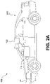
- system 100 may be included on a vehicle 200, as shown in FIG. 2A .
- vehicle 200 may be equipped with a processing unit 110 and any of the other components of system 100, as described above relative to FIG. 1 .
- vehicle 200 may be equipped with only a single image capture device (e.g., camera), in other embodiments, such as those discussed in connection with FIGS. 2B-2E , multiple image capture devices may be used.
- image capture devices 122 and 124 of vehicle 200 as shown in FIG. 2A , may be part of an ADAS (Advanced Driver Assistance Systems) imaging set.
- ADAS Advanced Driver Assistance Systems
- image capture devices included on vehicle 200 as part of the image acquisition unit 120 may be positioned at any suitable location.
- image capture device 122 may be located in the vicinity of the rearview mirror. This position may provide a line of sight similar to that of the driver of vehicle 200, which may aid in determining what is and is not visible to the driver.
- Image capture device 122 may be positioned at any location near the rearview mirror, but placing image capture device 122 on the driver side of the mirror may further aid in obtaining images representative of the driver's field of view and/or line of sight.
- image capture device 124 may be located on or in a bumper of vehicle 200. Such a location may be especially suitable for image capture devices having a wide field of view. The line of sight of bumper-located image capture devices can be different from that of the driver and, therefore, the bumper image capture device and driver may not always see the same objects.
- the image capture devices e.g., image capture devices 122, 124, and 126) may also be located in other locations.
- the image capture devices may be located on or in one or both of the side mirrors of vehicle 200, on the roof of vehicle 200, on the hood of vehicle 200, on the trunk of vehicle 200, on the sides of vehicle 200, mounted on, positioned behind, or positioned in front of any of the windows of vehicle 200, and mounted in or near light figures on the front and/or back of vehicle 200, etc.
- vehicle 200 may include various other components of system 100.
- processing unit 110 may be included on vehicle 200 either integrated with or separate from an engine control unit (ECU) of the vehicle.
- vehicle 200 may also be equipped with a position sensor 130, such as a GPS receiver and may also include a map database 160 and memory units 140 and 150.
- wireless transceiver 172 may and/or receive data over one or more networks (e.g., cellular networks, the Internet, etc.). For example, wireless transceiver 172 may upload data collected by system 100 to one or more servers, and download data from the one or more servers. Via wireless transceiver 172, system 100 may receive, for example, periodic or on demand updates to data stored in map database 160, memory 140, and/or memory 150. Similarly, wireless transceiver 172 may upload any data (e.g., images captured by image acquisition unit 120, data received by position sensor 130 or other sensors, vehicle control systems, etc.) from by system 100 and/or any data processed by processing unit 110 to the one or more servers.
- networks e.g., cellular networks, the Internet, etc.
- wireless transceiver 172 may upload data collected by system 100 to one or more servers, and download data from the one or more servers. Via wireless transceiver 172, system 100 may receive, for example, periodic or on demand updates to data stored in map database 160,
- System 100 may upload data to a server (e.g., to the cloud) based on a privacy level setting.
- system 100 may implement privacy level settings to regulate or limit the types of data (including metadata) sent to the server that may uniquely identify a vehicle and or driver/owner of a vehicle.
- privacy level settings may be set by user via, for example, wireless transceiver 172, be initialized by factory default settings, or by data received by wireless transceiver 172.
- system 100 may upload data according to a "high" privacy level, and under setting a setting, system 100 may transmit data (e.g., location information related to a route, captured images, etc.) without any details about the specific vehicle and/or driver/owner.
- system 100 may not include a vehicle identification number (VIN) or a name of a driver or owner of the vehicle, and may instead of transmit data, such as captured images and/or limited location information related to a route.
- VIN vehicle identification number
- a name of a driver or owner of the vehicle may instead of transmit data, such as captured images and/or limited location information related to a route.
- system 100 may transmit data to a server according to an "intermediate" privacy level and include additional information not included under a "high" privacy level, such as a make and/or model of a vehicle and/or a vehicle type (e.g., a passenger vehicle, sport utility vehicle, truck, etc.).
- system 100 may upload data according to a "low" privacy level. Under a "low" privacy level setting, system 100 may upload data and include information sufficient to uniquely identify a specific vehicle, owner/driver, and/or a portion or entirely of a route traveled by the vehicle.
- Such "low" privacy level data may include one or more of, for example, a VIN, a driver/owner name, an origination point of a vehicle prior to departure, an intended destination of the vehicle, a make and/or model of the vehicle, a type of the vehicle, etc.
- FIG. 2A is a diagrammatic side view representation of an exemplary vehicle imaging system consistent with the disclosed embodiments.
- FIG. 2B is a diagrammatic top view illustration of the embodiment shown in FIG. 2A .
- the disclosed embodiments may include a vehicle 200 including in its body a system 100 with a first image capture device 122 positioned in the vicinity of the rearview mirror and/or near the driver of vehicle 200, a second image capture device 124 positioned on or in a bumper region (e.g., one of bumper regions 210) of vehicle 200, and a processing unit 110.
- a vehicle 200 including in its body a system 100 with a first image capture device 122 positioned in the vicinity of the rearview mirror and/or near the driver of vehicle 200, a second image capture device 124 positioned on or in a bumper region (e.g., one of bumper regions 210) of vehicle 200, and a processing unit 110.
- a bumper region e.g., one of bumper regions 210
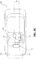
- image capture devices 122 and 124 may both be positioned in the vicinity of the rearview mirror and/or near the driver of vehicle 200. Additionally, while two image capture devices 122 and 124 are shown in FIGS. 2B and 2C , it should be understood that other embodiments may include more than two image capture devices. For example, in the embodiments shown in FIGS. 2D and 2E , first, second, and third image capture devices 122, 124, and 126, are included in the system 100 of vehicle 200.
- image capture device 122 may be positioned in the vicinity of the rearview mirror and/or near the driver of vehicle 200, and image capture devices 124 and 126 may be positioned on or in a bumper region (e.g., one of bumper regions 210) of vehicle 200.
- image capture devices 122, 124, and 126 may be positioned in the vicinity of the rearview mirror and/or near the driver seat of vehicle 200.
- the disclosed embodiments are not limited to any particular number and configuration of the image capture devices, and the image capture devices may be positioned in any appropriate location within and/or on vehicle 200.
- the first image capture device 122 may include any suitable type of image capture device.
- Image capture device 122 may include an optical axis.
- the image capture device 122 may include an Aptina M9V024 WVGA sensor with a global shutter.
- image capture device 122 may provide a resolution of 1280x960 pixels and may include a rolling shutter.
- Image capture device 122 may include various optical elements. In some embodiments one or more lenses may be included, for example, to provide a desired focal length and field of view for the image capture device. In some embodiments, image capture device 122 may be associated with a 6mm lens or a 12mm lens.
- image capture device 122 may be configured to capture images having a desired field-of-view (FOV) 202, as illustrated in FIG. 2D .
- FOV field-of-view
- image capture device 122 may be configured to have a regular FOV, such as within a range of 40 degrees to 56 degrees, including a 46 degree FOV, 50 degree FOV, 52 degree FOV, or greater.
- image capture device 122 may be configured to have a narrow FOV in the range of 23 to 40 degrees, such as a 28 degree FOV or 36 degree FOV.
- image capture device 122 may be configured to have a wide FOV in the range of 100 to 180 degrees.
- image capture device 122 may include a wide angle bumper camera or one with up to a 180 degree FOV.
- Such an image capture device may be used in place of a three image capture device configuration. Due to significant lens distortion, the vertical FOV of such an image capture device may be significantly less than 50 degrees in implementations in which the image capture device uses a radially symmetric lens. For example, such a lens may not be radially symmetric which would allow for a vertical FOV greater than 50 degrees with 100 degree horizontal FOV.
- the first image capture device 122 may acquire a plurality of first images relative to a scene associated with the vehicle 200.
- Each of the plurality of first images may be acquired as a series of image scan lines, which may be captured using a rolling shutter.
- Each scan line may include a plurality of pixels.
- the first image capture device 122 may have a scan rate associated with acquisition of each of the first series of image scan lines.
- the scan rate may refer to a rate at which an image sensor can acquire image data associated with each pixel included in a particular scan line.
- Image capture devices 122, 124, and 126 may contain any suitable type and number of image sensors, including CCD sensors or CMOS sensors, for example.
- a CMOS image sensor may be employed along with a rolling shutter, such that each pixel in a row is read one at a time, and scanning of the rows proceeds on a row-by-row basis until an entire image frame has been captured.
- the rows may be captured sequentially from top to bottom relative to the frame.
- one or more of the image capture devices may constitute a high resolution imager and may have a resolution greater than 5M pixel, 7M pixel, 10M pixel, or greater.
- a rolling shutter may result in pixels in different rows being exposed and captured at different times, which may cause skew and other image artifacts in the captured image frame.
- the image capture device 122 is configured to operate with a global or synchronous shutter, all of the pixels may be exposed for the same amount of time and during a common exposure period.
- the image data in a frame collected from a system employing a global shutter represents a snapshot of the entire FOV (such as FOV 202) at a particular time.
- FOV 202 the entire FOV
- each row in a frame is exposed and data is capture at different times.
- moving objects may appear distorted in an image capture device having a rolling shutter. This phenomenon will be described in greater detail below.
- the second image capture device 124 and the third image capturing device 126 may be any type of image capture device. Like the first image capture device 122, each of image capture devices 124 and 126 may include an optical axis. In one embodiment, each of image capture devices 124 and 126 may include an Aptina M9V024 WVGA sensor with a global shutter. Alternatively, each of image capture devices 124 and 126 may include a rolling shutter. Like image capture device 122, image capture devices 124 and 126 may be configured to include various lenses and optical elements.
- lenses associated with image capture devices 124 and 126 may provide FOVs (such as FOVs 204 and 206) that are the same as, or narrower than, a FOV (such as FOV 202) associated with image capture device 122.
- FOVs such as FOVs 204 and 206
- FOV 202 FOV 202
- image capture devices 124 and 126 may have FOVs of 40 degrees, 30 degrees, 26 degrees, 23 degrees, 20 degrees, or less.
- Image capture devices 124 and 126 may acquire a plurality of second and third images relative to a scene associated with the vehicle 200. Each of the plurality of second and third images may be acquired as a second and third series of image scan lines, which may be captured using a rolling shutter. Each scan line or row may have a plurality of pixels. Image capture devices 124 and 126 may have second and third scan rates associated with acquisition of each of image scan lines included in the second and third series.
- Each image capture device 122, 124, and 126 may be positioned at any suitable position and orientation relative to vehicle 200. The relative positioning of the image capture devices 122, 124, and 126 may be selected to aid in fusing together the information acquired from the image capture devices. For example, in some embodiments, a FOV (such as FOV 204) associated with image capture device 124 may overlap partially or fully with a FOV (such as FOV 202) associated with image capture device 122 and a FOV (such as FOV 206) associated with image capture device 126.
- FOV such as FOV 204
- FOV 206 FOV
- Image capture devices 122, 124, and 126 may be located on vehicle 200 at any suitable relative heights. In one instance, there may be a height difference between the image capture devices 122, 124, and 126, which may provide sufficient parallax information to enable stereo analysis. For example, as shown in FIG. 2A , the two image capture devices 122 and 124 are at different heights. There may also be a lateral displacement difference between image capture devices 122, 124, and 126, giving additional parallax information for stereo analysis by processing unit 110, for example. The difference in the lateral displacement may be denoted by d x , as shown in FIGS. 2C and 2D .
- fore or aft displacement may exist between image capture devices 122, 124, and 126.
- image capture device 122 may be located 0.5 to 2 meters or more behind image capture device 124 and/or image capture device 126. This type of displacement may enable one of the image capture devices to cover potential blind spots of the other image capture device(s).
- Image capture devices 122 may have any suitable resolution capability (e.g., number of pixels associated with the image sensor), and the resolution of the image sensor(s) associated with the image capture device 122 may be higher, lower, or the same as the resolution of the image sensor(s) associated with image capture devices 124 and 126.
- the image sensor(s) associated with image capture device 122 and/or image capture devices 124 and 126 may have a resolution of 640 ⁇ 480, 1024 ⁇ 768, 1280 ⁇ 960, or any other suitable resolution.
- the frame rate (e.g., the rate at which an image capture device acquires a set of pixel data of one image frame before moving on to capture pixel data associated with the next image frame) may be controllable.
- the frame rate associated with image capture device 122 may be higher, lower, or the same as the frame rate associated with image capture devices 124 and 126.
- the frame rate associated with image capture devices 122, 124, and 126 may depend on a variety of factors that may affect the timing of the frame rate.
- one or more of image capture devices 122, 124, and 126 may include a selectable pixel delay period imposed before or after acquisition of image data associated with one or more pixels of an image sensor in image capture device 122, 124, and/or 126.
- image data corresponding to each pixel may be acquired according to a clock rate for the device (e.g., one pixel per clock cycle).
- a clock rate for the device e.g., one pixel per clock cycle.
- one or more of image capture devices 122, 124, and 126 may include a selectable horizontal blanking period imposed before or after acquisition of image data associated with a row of pixels of an image sensor in image capture device 122, 124, and/or 126.
- image capture devices 122, 124, and/or 126 may include a selectable vertical blanking period imposed before or after acquisition of image data associated with an image frame of image capture device 122, 124, and 126.
- timing controls may enable synchronization of frame rates associated with image capture devices 122, 124, and 126, even where the line scan rates of each are different. Additionally, as will be discussed in greater detail below, these selectable timing controls, among other factors (e.g., image sensor resolution, maximum line scan rates, etc.) may enable synchronization of image capture from an area where the FOV of image capture device 122 overlaps with one or more FOVs of image capture devices 124 and 126, even where the field of view of image capture device 122 is different from the FOVs of image capture devices 124 and 126.
- image sensor resolution e.g., maximum line scan rates, etc.
- Frame rate timing in image capture device 122, 124, and 126 may depend on the resolution of the associated image sensors. For example, assuming similar line scan rates for both devices, if one device includes an image sensor having a resolution of 640 ⁇ 480 and another device includes an image sensor with a resolution of 1280 ⁇ 960, then more time will be required to acquire a frame of image data from the sensor having the higher resolution.
- Another factor that may affect the timing of image data acquisition in image capture devices 122, 124, and 126 is the maximum line scan rate. For example, acquisition of a row of image data from an image sensor included in image capture device 122, 124, and 126 will require some minimum amount of time. Assuming no pixel delay periods are added, this minimum amount of time for acquisition of a row of image data will be related to the maximum line scan rate for a particular device. Devices that offer higher maximum line scan rates have the potential to provide higher frame rates than devices with lower maximum line scan rates. In some embodiments, one or more of image capture devices 124 and 126 may have a maximum line scan rate that is higher than a maximum line scan rate associated with image capture device 122. In some embodiments, the maximum line scan rate of image capture device 124 and/or 126 may be 1.25, 1.5, 1.75, or 2 times or more than a maximum line scan rate of image capture device 122.
- image capture devices 122, 124, and 126 may have the same maximum line scan rate, but image capture device 122 may be operated at a scan rate less than or equal to its maximum scan rate.
- the system may be configured such that one or more of image capture devices 124 and 126 operate at a line scan rate that is equal to the line scan rate of image capture device 122.
- the system may be configured such that the line scan rate of image capture device 124 and/or image capture device 126 may be 1.25, 1.5, 1.75, or 2 times or more than the line scan rate of image capture device 122.
- image capture devices 122, 124, and 126 may be asymmetric. That is, they may include cameras having different fields of view (FOV) and focal lengths.
- the fields of view of image capture devices 122, 124, and 126 may include any desired area relative to an environment of vehicle 200, for example.
- one or more of image capture devices 122, 124, and 126 may be configured to acquire image data from an environment in front of vehicle 200, behind vehicle 200, to the sides of vehicle 200, or combinations thereof.
- each image capture device 122, 124, and/or 126 may be selectable (e.g., by inclusion of appropriate lenses etc.) such that each device acquires images of objects at a desired distance range relative to vehicle 200.
- image capture devices 122, 124, and 126 may acquire images of close-up objects within a few meters from the vehicle.
- Image capture devices 122, 124, and 126 may also be configured to acquire images of objects at ranges more distant from the vehicle (e.g., 25 m, 50 m, 100 m, 150 m, or more).
- the focal lengths of image capture devices 122, 124, and 126 may be selected such that one image capture device (e.g., image capture device 122) can acquire images of objects relatively close to the vehicle (e.g., within 10 m or within 20 m) while the other image capture devices (e.g., image capture devices 124 and 126) can acquire images of more distant objects (e.g., greater than 20 m, 50 m, 100 m, 150 m, etc.) from vehicle 200.
- one image capture device e.g., image capture device 122
- the other image capture devices e.g., image capture devices 124 and 1266
- images of more distant objects e.g., greater than 20 m, 50 m, 100 m, 150 m, etc.
- the FOV of one or more image capture devices 122, 124, and 126 may have a wide angle.
- image capture device 122 may be used to capture images of the area to the right or left of vehicle 200 and, in such embodiments, it may be desirable for image capture device 122 to have a wide FOV (e.g., at least 140 degrees).
- the field of view associated with each of image capture devices 122, 124, and 126 may depend on the respective focal lengths. For example, as the focal length increases, the corresponding field of view decreases.
- Image capture devices 122, 124, and 126 may be configured to have any suitable fields of view.
- image capture device 122 may have a horizontal FOV of 46 degrees
- image capture device 124 may have a horizontal FOV of 23 degrees
- image capture device 126 may have a horizontal FOV in between 23 and 46 degrees.
- image capture device 122 may have a horizontal FOV of 52 degrees
- image capture device 124 may have a horizontal FOV of 26 degrees
- image capture device 126 may have a horizontal FOV in between 26 and 52 degrees.
- a ratio of the FOV of image capture device 122 to the FOVs of image capture device 124 and/or image capture device 126 may vary from 1.5 to 2.0. In other embodiments, this ratio may vary between 1.25 and 2.25.
- System 100 may be configured so that a field of view of image capture device 122 overlaps, at least partially or fully, with a field of view of image capture device 124 and/or image capture device 126.
- system 100 may be configured such that the fields of view of image capture devices 124 and 126, for example, fall within (e.g., are narrower than) and share a common center with the field of view of image capture device 122.
- the image capture devices 122, 124, and 126 may capture adjacent FOVs or may have partial overlap in their FOVs.
- the fields of view of image capture devices 122, 124, and 126 may be aligned such that a center of the narrower FOV image capture devices 124 and/or 126 may be located in a lower half of the field of view of the wider FOV device 122.
- FIG. 2F is a diagrammatic representation of exemplary vehicle control systems, consistent with the disclosed embodiments.
- vehicle 200 may include throttling system 220, braking system 230, and steering system 240.
- System 100 may provide inputs (e.g., control signals) to one or more of throttling system 220, braking system 230, and steering system 240 over one or more data links (e.g., any wired and/or wireless link or links for transmitting data).
- data links e.g., any wired and/or wireless link or links for transmitting data.
- system 100 may provide control signals to one or more of throttling system 220, braking system 230, and steering system 240 to navigate vehicle 200 (e.g., by causing an acceleration, a turn, a lane shift, etc.). Further, system 100 may receive inputs from one or more of throttling system 220, braking system 230, and steering system 24 indicating operating conditions of vehicle 200 (e.g., speed, whether vehicle 200 is braking and/or turning, etc.). Further details are provided in connection with FIGS. 4-7 , below.
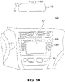
- vehicle 200 may also include a user interface 170 for interacting with a driver or a passenger of vehicle 200.
- user interface 170 in a vehicle application may include a touch screen 320, knobs 330, buttons 340, and a microphone 350.
- a driver or passenger of vehicle 200 may also use handles (e.g., located on or near the steering column of vehicle 200 including, for example, turn signal handles), buttons (e.g., located on the steering wheel of vehicle 200), and the like, to interact with system 100.
- handles e.g., located on or near the steering column of vehicle 200 including, for example, turn signal handles), buttons (e.g., located on the steering wheel of vehicle 200), and the like, to interact with system 100.
- microphone 350 may be positioned adjacent to a rearview mirror 310.
- image capture device 122 may be located near rearview mirror 310.
- user interface 170 may also include one or more speakers 360 (e.g., speakers of a vehicle audio system).
- system 100 may provide various notifications (e.g
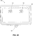
- FIGS. 3B-3D are illustrations of an exemplary camera mount 370 configured to be positioned behind a rearview mirror (e.g., rearview mirror 310) and against a vehicle windshield, consistent with disclosed embodiments.
- camera mount 370 may include image capture devices 122, 124, and 126.
- Image capture devices 124 and 126 may be positioned behind a glare shield 380, which may be flush against the vehicle windshield and include a composition of film and/or anti-reflective materials.
- glare shield 380 may be positioned such that the shield aligns against a vehicle windshield having a matching slope.
- each of image capture devices 122, 124, and 126 may be positioned behind glare shield 380, as depicted, for example, in FIG. 3D .
- the disclosed embodiments are not limited to any particular configuration of image capture devices 122, 124, and 126, camera mount 370, and glare shield 380.
- FIG. 3C is an illustration of camera mount 370 shown in FIG. 3B from a front perspective.
- system 100 can provide a wide range of functionality to analyze the surroundings of vehicle 200 and navigate vehicle 200 in response to the analysis.
- system 100 may provide a variety of features related to autonomous driving and/or driver assist technology.
- system 100 may analyze image data, position data (e.g., GPS location information), map data, speed data, and/or data from sensors included in vehicle 200.
- System 100 may collect the data for analysis from, for example, image acquisition unit 120, position sensor 130, and other sensors. Further, system 100 may analyze the collected data to determine whether or not vehicle 200 should take a certain action, and then automatically take the determined action without human intervention.
- system 100 may automatically control the braking, acceleration, and/or steering of vehicle 200 (e.g., by sending control signals to one or more of throttling system 220, braking system 230, and steering system 240). Further, system 100 may analyze the collected data and issue warnings and/or alerts to vehicle occupants based on the analysis of the collected data. Additional details regarding the various embodiments that are provided by system 100 are provided below.
- system 100 may provide drive assist functionality that uses a multi-camera system.
- the multi-camera system may use one or more cameras facing in the forward direction of a vehicle.
- the multi-camera system may include one or more cameras facing to the side of a vehicle or to the rear of the vehicle.
- system 100 may use a two-camera imaging system, where a first camera and a second camera (e.g., image capture devices 122 and 124) may be positioned at the front and/or the sides of a vehicle (e.g., vehicle 200).
- the first camera may have a field of view that is greater than, less than, or partially overlapping with, the field of view of the second camera.
- the first camera may be connected to a first image processor to perform monocular image analysis of images provided by the first camera
- the second camera may be connected to a second image processor to perform monocular image analysis of images provided by the second camera.
- the outputs (e.g., processed information) of the first and second image processors may be combined.
- the second image processor may receive images from both the first camera and second camera to perform stereo analysis.
- system 100 may use a three-camera imaging system where each of the cameras has a different field of view. Such a system may, therefore, make decisions based on information derived from objects located at varying distances both forward and to the sides of the vehicle.
- references to monocular image analysis may refer to instances where image analysis is performed based on images captured from a single point of view (e.g., from a single camera).
- Stereo image analysis may refer to instances where image analysis is performed based on two or more images captured with one or more variations of an image capture parameter.
- captured images suitable for performing stereo image analysis may include images captured: from two or more different positions, from different fields of view, using different focal lengths, along with parallax information, etc.
- system 100 may implement a three camera configuration using image capture devices 122, 124, and 126.
- image capture device 122 may provide a narrow field of view (e.g., 34 degrees, or other values selected from a range of about 20 to 45 degrees, etc.)
- image capture device 124 may provide a wide field of view (e.g., 150 degrees or other values selected from a range of about 100 to about 180 degrees)
- image capture device 126 may provide an intermediate field of view (e.g., 46 degrees or other values selected from a range of about 35 to about 60 degrees).
- image capture device 126 may act as a main or primary camera.
- Image capture devices 122, 124, and 126 may be positioned behind rearview mirror 310 and positioned substantially side-by-side (e.g., 6 cm apart). Further, in some embodiments, as discussed above, one or more of image capture devices 122, 124, and 126 may be mounted behind glare shield 380 that is flush with the windshield of vehicle 200. Such shielding may act to minimize the impact of any reflections from inside the car on image capture devices 122, 124, and 126.
- the wide field of view camera (e.g., image capture device 124 in the above example) may be mounted lower than the narrow and main field of view cameras (e.g., image devices 122 and 126 in the above example).
- This configuration may provide a free line of sight from the wide field of view camera.
- the cameras may be mounted close to the windshield of vehicle 200, and may include polarizers on the cameras to damp reflected light.
- a three camera system may provide certain performance characteristics. For example, some embodiments may include an ability to validate the detection of objects by one camera based on detection results from another camera.
- processing unit 110 may include, for example, three processing devices (e.g., three EyeQ series of processor chips, as discussed above), with each processing device dedicated to processing images captured by one or more of image capture devices 122, 124, and 126.
- a first processing device may receive images from both the main camera and the narrow field of view camera, and perform vision processing of the narrow FOV camera to, for example, detect other vehicles, pedestrians, lane marks, traffic signs, traffic lights, and other road objects. Further, the first processing device may calculate a disparity of pixels between the images from the main camera and the narrow camera and create a 3D reconstruction of the environment of vehicle 200. The first processing device may then combine the 3D reconstruction with 3D map data or with 3D information calculated based on information from another camera.
- the second processing device may receive images from main camera and perform vision processing to detect other vehicles, pedestrians, lane marks, traffic signs, traffic lights, and other road objects. Additionally, the second processing device may calculate a camera displacement and, based on the displacement, calculate a disparity of pixels between successive images and create a 3D reconstruction of the scene (e.g., a structure from motion). The second processing device may send the structure from motion based 3D reconstruction to the first processing device to be combined with the stereo 3D images.
- a 3D reconstruction of the scene e.g., a structure from motion
- the third processing device may receive images from the wide FOV camera and process the images to detect vehicles, pedestrians, lane marks, traffic signs, traffic lights, and other road objects.
- the third processing device may further execute additional processing instructions to analyze images to identify objects moving in the image, such as vehicles changing lanes, pedestrians, etc.
- having streams of image-based information captured and processed independently may provide an opportunity for providing redundancy in the system.
- redundancy may include, for example, using a first image capture device and the images processed from that device to validate and/or supplement information obtained by capturing and processing image information from at least a second image capture device.
- system 100 may use two image capture devices (e.g., image capture devices 122 and 124) in providing navigation assistance for vehicle 200 and use a third image capture device (e.g., image capture device 126) to provide redundancy and validate the analysis of data received from the other two image capture devices.
- image capture devices 122 and 124 may provide images for stereo analysis by system 100 for navigating vehicle 200
- image capture device 126 may provide images for monocular analysis by system 100 to provide redundancy and validation of information obtained based on images captured from image capture device 122 and/or image capture device 124.
- image capture device 126 (and a corresponding processing device) may be considered to provide a redundant sub-system for providing a check on the analysis derived from image capture devices 122 and 124 (e.g., to provide an automatic emergency braking (AEB) system).
- AEB automatic emergency braking
- redundancy and validation of received data may be supplemented based on information received from one more sensors (e.g., radar, lidar, acoustic sensors, information received from one or more transceivers outside of a vehicle, etc.).
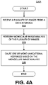
- FIG. 4A is a flowchart showing an exemplary process 500A for causing one or more navigational responses based on monocular image analysis, consistent with disclosed embodiments.
- processing unit 110 may receive a plurality of images via data interface 128 between processing unit 110 and image acquisition unit 120.
- a camera included in image acquisition unit 120 may capture a plurality of images of an area forward of vehicle 200 (or to the sides or rear of a vehicle, for example) and transmit them over a data connection (e.g., digital, wired, USB, wireless, Bluetooth, etc.) to processing unit 110.
- a data connection e.g., digital, wired, USB, wireless, Bluetooth, etc.
- Processing unit 110 may execute monocular image analysis module 402 to analyze the plurality of images at step 520, as described in further detail in connection with FIGS. 4B-4C below. By performing the analysis, processing unit 110 may detect a set of features within the set of images, such as lane markings, vehicles, pedestrians, road signs, highway exit ramps, traffic lights, and the like.
- Processing unit 110 may also execute monocular image analysis module 402 to detect various road hazards at step 520, such as, for example, parts of a truck tire, fallen road signs, loose cargo, small animals, and the like.
- Road hazards may vary in structure, shape, size, and color, which may make detection of such hazards more challenging.
- processing unit 110 may execute monocular image analysis module 402 to perform multi-frame analysis on the plurality of images to detect road hazards. For example, processing unit 110 may estimate camera motion between consecutive image frames and calculate the disparities in pixels between the frames to construct a 3D-map of the road. Processing unit 110 may then use the 3D-map to detect the road surface, as well as hazards existing above the road surface.
- processing unit 110 may execute navigational response module 408 to cause one or more navigational responses in vehicle 200 based on the analysis performed at step 520.
- Navigational responses may include, for example, a turn, a lane shift, a change in acceleration, and the like.
- processing unit 110 may use data derived from execution of velocity and acceleration module 406 to cause the one or more navigational responses.
- multiple navigational responses may occur simultaneously, in sequence, or any combination thereof. For instance, processing unit 110 may cause vehicle 200 to shift one lane over and then accelerate by, for example, sequentially transmitting control signals to steering system 240 and throttling system 220 of vehicle 200. Alternatively, processing unit 110 may cause vehicle 200 to brake while at the same time shifting lanes by, for example, simultaneously transmitting control signals to braking system 230 and steering system 240 of vehicle 200.
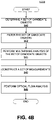
- FIG. 4B is a flowchart showing an exemplary process 500B for detecting one or more vehicles and/or pedestrians in a set of images, consistent with disclosed embodiments.
- Processing unit 110 may execute monocular image analysis module 402 to implement process 500B.
- processing unit 110 may determine a set of candidate objects representing possible vehicles and/or pedestrians. For example, processing unit 110 may scan one or more images, compare the images to one or more predetermined patterns, and identify within each image possible locations that may contain objects of interest (e.g., vehicles, pedestrians, or portions thereof).
- objects of interest e.g., vehicles, pedestrians, or portions thereof.
- the predetermined patterns may be designed in such a way to achieve a high rate of "false hits" and a low rate of "misses.”
- processing unit 110 may use a low threshold of similarity to predetermined patterns for identifying candidate objects as possible vehicles or pedestrians. Doing so may allow processing unit 110 to reduce the probability of missing (e.g., not identifying) a candidate object representing a vehicle or pedestrian.
- processing unit 110 may filter the set of candidate objects to exclude certain candidates (e.g., irrelevant or less relevant objects) based on classification criteria.
- criteria may be derived from various properties associated with object types stored in a database (e.g., a database stored in memory 140). Properties may include object shape, dimensions, texture, position (e.g., relative to vehicle 200), and the like.
- processing unit 110 may use one or more sets of criteria to reject false candidates from the set of candidate objects.
- processing unit 110 may analyze multiple frames of images to determine whether objects in the set of candidate objects represent vehicles and/or pedestrians. For example, processing unit 110 may track a detected candidate object across consecutive frames and accumulate frame-by-frame data associated with the detected object (e.g., size, position relative to vehicle 200, etc.). Additionally, processing unit 110 may estimate parameters for the detected object and compare the object's frame-by-frame position data to a predicted position.
- processing unit 110 may estimate parameters for the detected object and compare the object's frame-by-frame position data to a predicted position.
- processing unit 110 may construct a set of measurements for the detected objects. Such measurements may include, for example, position, velocity, and acceleration values (relative to vehicle 200) associated with the detected objects.
- processing unit 110 may construct the measurements based on estimation techniques using a series of time-based observations such as Kalman filters or linear quadratic estimation (LQE), and/or based on available modeling data for different object types (e.g., cars, trucks, pedestrians, bicycles, road signs, etc.).
- the Kalman filters may be based on a measurement of an object's scale, where the scale measurement is proportional to a time to collision (e.g., the amount of time for vehicle 200 to reach the object).
- processing unit 110 may identify vehicles and pedestrians appearing within the set of captured images and derive information (e.g., position, speed, size) associated with the vehicles and pedestrians. Based on the identification and the derived information, processing unit 110 may cause one or more navigational responses in vehicle 200, as described in connection with FIG. 4A , above.
- information e.g., position, speed, size
- processing unit 110 may perform an optical flow analysis of one or more images to reduce the probabilities of detecting a "false hit" and missing a candidate object that represents a vehicle or pedestrian.
- the optical flow analysis may refer to, for example, analyzing motion patterns relative to vehicle 200 in the one or more images associated with other vehicles and pedestrians, and that are distinct from road surface motion.
- Processing unit 110 may calculate the motion of candidate objects by observing the different positions of the objects across multiple image frames, which are captured at different times.
- Processing unit 110 may use the position and time values as inputs into mathematical models for calculating the motion of the candidate objects.
- optical flow analysis may provide another method of detecting vehicles and pedestrians that are nearby vehicle 200.
- Processing unit 110 may perform optical flow analysis in combination with steps 540-546 to provide redundancy for detecting vehicles and pedestrians and increase the reliability of system 100.
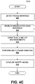
- FIG. 4C is a flowchart showing an exemplary process 500C for detecting road marks and/or lane geometry information in a set of images, consistent with disclosed embodiments.
- Processing unit 110 may execute monocular image analysis module 402 to implement process 500C.
- processing unit 110 may detect a set of objects by scanning one or more images. To detect segments of lane markings, lane geometry information, and other pertinent road marks, processing unit 110 may filter the set of objects to exclude those determined to be irrelevant (e.g., minor potholes, small rocks, etc.).
- processing unit 110 may group together the segments detected in step 550 belonging to the same road mark or lane mark. Based on the grouping, processing unit 110 may develop a model to represent the detected segments, such as a mathematical model.
- processing unit 110 may construct a set of measurements associated with the detected segments.
- processing unit 110 may create a projection of the detected segments from the image plane onto the real-world plane.
- the projection may be characterized using a 3rd-degree polynomial having coefficients corresponding to physical properties such as the position, slope, curvature, and curvature derivative of the detected road.
- processing unit 110 may take into account changes in the road surface, as well as pitch and roll rates associated with vehicle 200.
- processing unit 110 may model the road elevation by analyzing position and motion cues present on the road surface. Further, processing unit 110 may estimate the pitch and roll rates associated with vehicle 200 by tracking a set of feature points in the one or more images.
- processing unit 110 may perform multi-frame analysis by, for example, tracking the detected segments across consecutive image frames and accumulating frame-by-frame data associated with detected segments. As processing unit 110 performs multi-frame analysis, the set of measurements constructed at step 554 may become more reliable and associated with an increasingly higher confidence level. Thus, by performing steps 550, 552, 554, and 556, processing unit 110 may identify road marks appearing within the set of captured images and derive lane geometry information. Based on the identification and the derived information, processing unit 110 may cause one or more navigational responses in vehicle 200, as described in connection with FIG. 4A , above.
- processing unit 110 may consider additional sources of information to further develop a safety model for vehicle 200 in the context of its surroundings.
- Processing unit 110 may use the safety model to define a context in which system 100 may execute autonomous control of vehicle 200 in a safe manner.
- processing unit 110 may consider the position and motion of other vehicles, the detected road edges and barriers, and/or general road shape descriptions extracted from map data (such as data from map database 160). By considering additional sources of information, processing unit 110 may provide redundancy for detecting road marks and lane geometry and increase the reliability of system 100.
- the disclosed systems and methods may use a sparse map for autonomous vehicle navigation.
- the sparse map may be for autonomous vehicle navigation along a road segment.
- the sparse map may provide sufficient information for navigating an autonomous vehicle without storing and/or updating a large quantity of data.
- an autonomous vehicle may use the sparse map to navigate one or more roads based on one or more stored trajectories.
- the disclosed systems and methods may generate a sparse map for autonomous vehicle navigation.
- the sparse map may provide sufficient information for navigation without requiring excessive data storage or data transfer rates.
- a vehicle which may be an autonomous vehicle
- the sparse map may use the sparse map to navigate one or more roads.
- the sparse map may include data related to a road and potentially landmarks along the road that may be sufficient for vehicle navigation, but which also exhibit small data footprints.
- the sparse data maps described in detail below may require significantly less storage space and data transfer bandwidth as compared with digital maps including detailed map information, such as image data collected along a road.
- the sparse data map may store three-dimensional polynomial representations of preferred vehicle paths along a road. These paths may require very little data storage space.
- landmarks may be identified and included in the sparse map road model to aid in navigation. These landmarks may be located at any spacing suitable for enabling vehicle navigation, but in some cases, such landmarks need not be identified and included in the model at high densities and short spacings. Rather, in some cases, navigation may be possible based on landmarks that are spaced apart by at least 50 meters, at least 100 meters, at least 500 meters, at least 1 kilometer, or at least 2 kilometers.
- the sparse map may be generated based on data collected or measured by vehicles equipped with various sensors and devices, such as image capture devices, Global Positioning System sensors, motion sensors, etc., as the vehicles travel along roadways.
- the sparse map may be generated based on data collected during multiple drives of one or more vehicles along a particular roadway. Generating a sparse map using multiple drives of one or more vehicles may be referred to as "crowdsourcing" a sparse map.
- an autonomous vehicle system may use a sparse map for navigation.
- the disclosed systems and methods may distribute a sparse map for generating a road navigation model for an autonomous vehicle and may navigate an autonomous vehicle along a road segment using a sparse map and/or a generated road navigation model.
- Sparse maps consistent with the present disclosure may include one or more three-dimensional contours that may represent predetermined trajectories that autonomous vehicles may traverse as they move along associated road segments.
- Sparse maps consistent with the present disclosure may also include data representing one or more road features. Such road features may include recognized landmarks, road signature profiles, and any other road-related features useful in navigating a vehicle. Sparse maps consistent with the present disclosure may enable autonomous navigation of a vehicle based on relatively small amounts of data included in the sparse map. For example, rather than including detailed representations of a road, such as road edges, road curvature, images associated with road segments, or data detailing other physical features associated with a road segment, the disclosed embodiments of the sparse map may require relatively little storage space (and relatively little bandwidth when portions of the sparse map are transferred to a vehicle) but may still adequately provide for autonomous vehicle navigation. The small data footprint of the disclosed sparse maps, discussed in further detail below, may be achieved in some embodiments by storing representations of road-related elements that require small amounts of data but still enable autonomous navigation.
- the disclosed sparse maps may store polynomial representations of one or more trajectories that a vehicle may follow along the road.
- a vehicle may be navigated along a particular road segment without, in some cases, having to interpret physical aspects of the road, but rather, by aligning its path of travel with a trajectory (e.g., a polynomial spline) along the particular road segment.
- a trajectory e.g., a polynomial spline
- the vehicle may be navigated based mainly upon the stored trajectory (e.g., a polynomial spline) that may require much less storage space than an approach involving storage of roadway images, road parameters, road layout, etc.
- the disclosed sparse maps may also include small data objects that may represent a road feature.
- the small data objects may include digital signatures, which are derived from a digital image (or a digital signal) that was obtained by a sensor (e.g., a camera or other sensor, such as a suspension sensor) onboard a vehicle traveling along the road segment.
- the digital signature may have a reduced size relative to the signal that was acquired by the sensor.
- the digital signature may be created to be compatible with a classifier function that is configured to detect and to identify the road feature from the signal that is acquired by the sensor, for example, during a subsequent drive.
- a digital signature may be created such that the digital signature has a footprint that is as small as possible, while retaining the ability to correlate or match the road feature with the stored signature based on an image (or a digital signal generated by a sensor, if the stored signature is not based on an image and/or includes other data) of the road feature that is captured by a camera onboard a vehicle traveling along the same road segment at a subsequent time.
- a size of the data objects may be further associated with a uniqueness of the road feature.
- a road feature that is detectable by a camera onboard a vehicle, and where the camera system onboard the vehicle is coupled to a classifier that is capable of distinguishing the image data corresponding to that road feature as being associated with a particular type of road feature, for example, a road sign, and where such a road sign is locally unique in that area (e.g., there is no identical road sign or road sign of the same type nearby), it may be sufficient to store data indicating the type of the road feature and its location.
- road features may be stored as small data objects that may represent a road feature in relatively few bytes, while at the same time providing sufficient information for recognizing and using such a feature for navigation.
- a road sign may be identified as a recognized landmark on which navigation of a vehicle may be based.
- a representation of the road sign may be stored in the sparse map to include, e.g., a few bytes of data indicating a type of landmark (e.g., a stop sign) and a few bytes of data indicating a location of the landmark (e.g., coordinates).
- Navigating based on such data-light representations of the landmarks may provide a desired level of navigational functionality associated with sparse maps without significantly increasing the data overhead associated with the sparse maps.
- This lean representation of landmarks may take advantage of the sensors and processors included onboard such vehicles that are configured to detect, identify, and/or classify certain road features.
- the sparse map may use data indicating a type of a landmark (a sign or a specific type of sign), and during navigation (e.g., autonomous navigation) when a camera onboard an autonomous vehicle captures an image of the area including a sign (or of a specific type of sign), the processor may process the image, detect the sign (if indeed present in the image), classify the image as a sign (or as a specific type of sign), and correlate the location of the image with the location of the sign as stored in the sparse map.
- a type of a landmark a sign or a specific type of sign
- the processor may process the image, detect the sign (if indeed present in the image), classify the image as a sign (or as a specific type of sign), and correlate the location of the image with the location of the sign as stored in the sparse map.
- a sparse map may include at least one line representation of a road surface feature extending along a road segment and a plurality of landmarks associated with the road segment.
- the sparse map may be generated via "crowdsourcing," for example, through image analysis of a plurality of images acquired as one or more vehicles traverse the road segment.
- a sparse may include information relating to various other road features.
- FIG. 5A illustrates a representation of curves along a particular road segment that may be stored in a sparse map.
- a single lane of a road may be modeled by a three-dimensional polynomial description of left and right sides of the road.
- a sparse map may describe a lanes network using a combination of geometry descriptors and meta-data.
- the geometry may be described by polynomials or splines as described above.
- the meta-data may describe the number of lanes, special characteristics (such as a car pool lane), and possibly other sparse labels. The total footprint of such indicators may be negligible.
- a sparse map may include at least one line representation of a road surface feature extending along the road segment, each line representation representing a path along the road segment substantially corresponding with the road surface feature.
- the at least one line representation of the road surface feature may include a spline, a polynomial representation, or a curve.
- the road surface feature may include at least one of a road edge or a lane marking.
- the road surface feature may be identified through image analysis of a plurality of images acquired as one or more vehicles traverse the road segment.
- FIG. 5A shows polynomial representations of trajectories captured during a process of building or maintaining a sparse map.
- a polynomial representation of a target trajectory included in a sparse map may be determined based on two or more reconstructed trajectories of prior traversals of vehicles along the same road segment.
- the polynomial representation of the target trajectory included in a sparse map may be an aggregation of two or more reconstructed trajectories of prior traversals of vehicles along the same road segment.
- the polynomial representation of the target trajectory included in a sparse map may be an average of the two or more reconstructed trajectories of prior traversals of vehicles along the same road segment.
- Other mathematical operations may also be used to construct a target trajectory along a road path based on reconstructed trajectories collected from vehicles traversing along a road segment.
- a road segment 900 may be travelled by a number of vehicles 200 at different times.
- Each vehicle 200 may collect data relating to a path that the vehicle took along the road segment.
- the path traveled by a particular vehicle may be determined based on camera data, accelerometer information, speed sensor information, and/or GPS information, among other potential sources.
- Such data may be used to reconstruct trajectories of vehicles traveling along the road segment, and based on these reconstructed trajectories, a target trajectory (or multiple target trajectories) may be determined for the particular road segment.
- target trajectories may represent a preferred path of a host vehicle (e.g., guided by an autonomous navigation system) as the vehicle travels along the road segment.
- a first reconstructed trajectory 901 may be determined based on data received from a first vehicle traversing road segment 900 at a first time period (e.g., day 1), a second reconstructed trajectory 902 may be obtained from a second vehicle traversing road segment 900 at a second time period (e.g., day 2), and a third reconstructed trajectory 903 may be obtained from a third vehicle traversing road segment 900 at a third time period (e.g., day 3).
- Each trajectory 901, 902, and 903 may be represented by a polynomial, such as a three-dimensional polynomial. It should be noted that in some embodiments, any of the reconstructed trajectories may be assembled onboard the vehicles traversing road segment 900.
- such reconstructed trajectories may be determined on a server side based on information received from vehicles traversing road segment 900.
- vehicles 200 may transmit data to one or more servers relating to their motion along road segment 900 (e.g., steering angle, heading, time, position, speed, sensed road geometry, and/or sensed landmarks, among things).
- the server may reconstruct trajectories for vehicles 200 based on the received data.
- the server may also generate a target trajectory for guiding navigation of autonomous vehicle that will travel along the same road segment 900 at a later time based on the first, second, and third trajectories 901, 902, and 903.
- each target trajectory included in a sparse map may be determined based on two or more reconstructed trajectories of vehicles traversing the same road segment.
- the target trajectory is represented by 910.
- the target trajectory 910 may be generated based on an average of the first, second, and third trajectories 901, 902, and 903.
- the target trajectory 910 included in a sparse map may be an aggregation (e.g., a weighted combination) of two or more reconstructed trajectories. Aligning drive data to construct trajectories is further discussed below.
- FIGS. 5B and 5C further illustrate the concept of target trajectories associated with road segments present within a geographic region 911.
- a first road segment 920 within geographic region 911 may include a multilane road, which includes two lanes 922 designated for vehicle travel in a first direction and two additional lanes 924 designated for vehicle travel in a second direction opposite to the first direction. Lanes 922 and lanes 924 may be separated by a double yellow line 923.
- Geographic region 911 may also include a branching road segment 930 that intersects with road segment 920.
- Road segment 930 may include a two-lane road, each lane being designated for a different direction of travel.
- Geographic region 911 may also include other road features, such as a stop line 932, a stop sign 934, a speed limit sign 936, and a hazard sign 938.
- a sparse map may include a local map 940 including a road model for assisting with autonomous navigation of vehicles within geographic region 911.
- local map 940 may include target trajectories for one or more lanes associated with road segments 920 and/or 930 within geographic region 911.
- local map 940 may include target trajectories 941 and/or 942 that an autonomous vehicle may access or rely upon when traversing lanes 922.
- local map 940 may include target trajectories 943 and/or 944 that an autonomous vehicle may access or rely upon when traversing lanes 924.
- local map 940 may include target trajectories 945 and/or 946 that an autonomous vehicle may access or rely upon when traversing road segment 930.
- Target trajectory 947 represents a preferred path an autonomous vehicle should follow when transitioning from lanes 920 (and specifically, relative to target trajectory 941 associated with a right-most lane of lanes 920) to road segment 930 (and specifically, relative to a target trajectory 945 associated with a first side of road segment 930.
- target trajectory 948 represents a preferred path an autonomous vehicle should follow when transitioning from road segment 930 (and specifically, relative to target trajectory 946) to a portion of road segment 924 (and specifically, as shown, relative to a target trajectory 943 associated with a left lane of lanes 924.
- a sparse map may also include representations of other road-related features associated with geographic region 911.
- a sparse map may also include representations of one or more landmarks identified in geographic region 911.
- Such landmarks may include a first landmark 950 associated with stop line 932, a second landmark 952 associated with stop sign 934, a third landmark associated with speed limit sign 954, and a fourth landmark 956 associated with hazard sign 938.
- Such landmarks may be used, for example, to assist an autonomous vehicle in determining its current location relative to any of the shown target trajectories, such that the vehicle may adjust its heading to match a direction of the target trajectory at the determined location.
- a sparse map may also include road signature profiles.
- road signature profiles may be associated with any discernible/measurable variation in at least one parameter associated with a road.
- such profiles may be associated with variations in road surface information such as variations in surface roughness of a particular road segment, variations in road width over a particular road segment, variations in distances between dashed lines painted along a particular road segment, variations in road curvature along a particular road segment, etc.
- FIG. 5D shows an example of a road signature profile 960.
- profile 960 may represent any of the parameters mentioned above, or others, in one example, profile 960 may represent a measure of road surface roughness, as obtained, for example, by monitoring one or more sensors providing outputs indicative of an amount of suspension displacement as a vehicle travels a particular road segment.
- profile 960 may represent variation in road width, as determined based on image data obtained via a camera onboard a vehicle traveling a particular road segment.
- Such profiles may be useful, for example, in determining a particular location of an autonomous vehicle relative to a particular target trajectory. That is, as it traverses a road segment, an autonomous vehicle may measure a profile associated with one or more parameters associated with the road segment.
- the measured and predetermined profiles may be used (e.g., by overlaying corresponding sections of the measured and predetermined profiles) in order to determine a current position along the road segment and, therefore, a current position relative to a target trajectory for the road segment.
- a sparse map may include different trajectories based on different characteristics associated with a user of autonomous vehicles, environmental conditions, and/or other parameters relating to driving. For example, in some embodiments, different trajectories may be generated based on different user preferences and/or profiles. A sparse map including such different trajectories may be provided to different autonomous vehicles of different users. For example, some users may prefer to avoid toll roads, while others may prefer to take the shortest or fastest routes, regardless of whether there is a toll road on the route. The disclosed systems may generate different sparse maps with different trajectories based on such different user preferences or profiles. As another example, some users may prefer to travel in a fast moving lane, while others may prefer to maintain a position in the central lane at all times.
- Different trajectories may be generated and included in a sparse map based on different environmental conditions, such as day and night, snow, rain, fog, etc.
- Autonomous vehicles driving under different environmental conditions may be provided with a sparse map generated based on such different environmental conditions.
- cameras provided on autonomous vehicles may detect the environmental conditions, and may provide such information back to a server that generates and provides sparse maps.
- the server may generate or update an already generated a sparse map to include trajectories that may be more suitable or safer for autonomous driving under the detected environmental conditions.
- the update of a sparse map based on environmental conditions may be performed dynamically as the autonomous vehicles are traveling along roads.
- Other different parameters relating to driving may also be used as a basis for generating and providing different sparse maps to different autonomous vehicles. For example, when an autonomous vehicle is traveling at a high speed, turns may be tighter. Trajectories associated with specific lanes, rather than roads, may be included in a sparse map such that the autonomous vehicle may maintain within a specific lane as the vehicle follows a specific trajectory. When an image captured by a camera onboard the autonomous vehicle indicates that the vehicle has drifted outside of the lane (e.g., crossed the lane mark), an action may be triggered within the vehicle to bring the vehicle back to the designated lane according to the specific trajectory.
- FIG. 6 illustrates an example autonomous vehicle road navigation model represented by a plurality of three dimensional splines 1001, 1002, and 1003.
- the curves 1001, 1002, and 1003 shown in FIG. 10 are for illustration purpose only.
- Each spline may include one or more three dimensional polynomials connecting a plurality of data points 1010.
- Each polynomial may be a first order polynomial, a second order polynomial, a third order polynomial, or a combination of any suitable polynomials having different orders.
- Each data point 1010 may be associated with the navigation information received from a plurality of vehicles.
- each data point 1010 may be associated with data related to landmarks (e.g., size, location, and identification information of landmarks) and/or road signature profiles (e.g., road geometry, road roughness profile, road curvature profile, road width profile). In some embodiments, some data points 1010 may be associated with data related to landmarks, and others may be associated with data related to road signature profiles.
- landmarks e.g., size, location, and identification information of landmarks
- road signature profiles e.g., road geometry, road roughness profile, road curvature profile, road width profile.
- some data points 1010 may be associated with data related to landmarks, and others may be associated with data related to road signature profiles.
- FIG. 7 illustrates raw location data 1110 (e.g., GPS data) received from five separate drives.
- One drive may be separate from another drive if it was traversed by separate vehicles at the same time, by the same vehicle at separate times, or by separate vehicles at separate times.
- a remote server may generate a map skeleton 1120 using one or more statistical techniques to determine whether variations in the raw location data 1110 represent actual divergences or statistical errors.
- Each path within skeleton 1120 may be linked back to the raw data 1110 that formed the path.
- Skeleton 1120 may not be detailed enough to be used to navigate a vehicle (e.g., because it combines drives from multiple lanes on the same road unlike the splines described above) but may provide useful topological information and may be used to define intersections.
- an autonomous vehicle in addition to navigational models, an autonomous vehicle (whether full autonomous, e.g., a self-driving vehicle, or partially autonomous, e.g., one or more driver assist systems or functions) generally uses a driving policy to ensure safety of other drivers and pedestrians as well as comfort of the passengers inside.
- an autonomous vehicle may sense a navigational state in an environment of a host vehicle.
- the vehicle may rely upon input from various sensors and sensing systems associated with the host vehicle. These inputs may include images or image streams from one or more onboard cameras, GPS position information, accelerometer outputs, user feedback, or user inputs to one or more user interface devices, radar, lidar, etc.
- Sensing which may include data from cameras and/or any other available sensors, along with map information, may be collected, analyzed, and formulated into a "sensed state," describing information extracted from a scene in the environment of the host vehicle.
- the sensed state may include sensed information relating to target vehicles, lane markings, pedestrians, traffic lights, road geometry, lane shape, obstacles, distances to other objects/vehicles, relative velocities, relative accelerations, among any other potential sensed information.
- Supervised machine learning may be implemented in order to produce a sensing state output based on sensed data provided.
- the output of the sensing module may represent a sensed navigational "state" of the host vehicle, which may be used in a driving policy, as described below.
- a sensed state may be developed based on image data received from one or more cameras or image sensors associated with a host vehicle
- a sensed state for use in navigation may be developed using any suitable sensor or combination of sensors.
- the sensed state may be developed without reliance upon captured image data.
- any of the navigational principles described herein may be applicable to sensed states developed based on captured image data as well as sensed states developed using other non-image based sensors.
- the sensed state may also be determined via sources external to the host vehicle.
- a sensed state may be developed in full or in part based on information received from sources remote from the host vehicle (e.g., based on sensor information, processed state information, etc. shared from other vehicles, shared from a central server, or from any other source of information relevant to a navigational state of the host vehicle).
- the autonomous vehicle may implement a desired driving policy in order to decide on one or more navigational actions for the host vehicle to take in response to the sensed navigational state. If there are no other agents (e.g., target vehicles or pedestrians) present in the environment of the host vehicle, the sensed state input may be handled in a relatively straightforward manner. The task becomes more complex when the sensed state requires negotiation with one or more other agents.
- the technology used to generate the output of from the driving policy may include reinforcement learning (discussed in more detail below).
- the output of the driving policy may include at least one navigational action for the host vehicle and may include a desired acceleration (which may translate to an updated speed for the host vehicle), a desired yaw rate for the host vehicle, a desired trajectory, among other potential desired navigational actions.
- the autonomous vehicle may develop control instructions for one or more actuators or controlled devices associated with the host vehicle.
- actuators and devices may include an accelerator, one or more steering controls, a brake, a signal transmitter, a display, or any other actuator or device that may be controlled as part of a navigation operation associated with a host vehicle.
- aspects of control theory may be used to generate the control instructions.
- the instructions to controllable components of the host vehicle may implement the desired navigational goals or requirements of the driving policy.
- a trained system trained through reinforcement learning may be used to implement the driving policy.
- the driving policy may be implemented without a machine learning approach, by using specified algorithms to "manually" address the various scenarios that may arise during autonomous navigation. Such an approach, however, while viable, may result in a driving policy that is too simplistic and may lack the flexibility of a trained system based on machine learning.
- a trained system may be better equipped to handle complex navigational states and may better determine whether a taxi is parking or is stopping to pick up or drop off a passenger; determine whether a pedestrian intends to cross the street ahead of the host vehicle; balance unexpected behavior of other drivers with defensiveness; negotiate in dense traffic involving target vehicles and/or pedestrians; decide when to suspend certain navigational rules or augment other rules; anticipate un-sensed, but anticipated conditions (e.g., whether a pedestrian will emerge from behind a car or obstacle); etc.
- a trained system based on reinforcement learning may also be better equipped to address a state space that is continuous and high-dimensional along with an action space that is continuous.
- Training of the system using reinforcement learning may involve learning a driving policy in order to map from sensed states to navigational actions.
- a driving policy may be a function ⁇ : S ⁇ A, where S is a set of states and A ⁇ R 2 is the action space (e.g., desired speed, acceleration, yaw commands, etc.).
- the system may be trained through exposure to various navigational states, having the system apply the policy, providing a reward (based on a reward function designed to reward desirable navigational behavior). Based on the reward feedback, the system may "learn" the policy and becomes trained in producing desirable navigational actions. For example, the learning system may observe the current state s t ⁇ S and decide on an action a t ⁇ A based on a policy ⁇ : S ⁇ D A . Based on the decided action (and implementation of the action), the environment moves to the next state s t +1 ⁇ S for observation by the learning system. For each action developed in response to the observed state, the feedback to the learning system is a reward signal r 1 , r 2 , ....
- the goal of Reinforcement Learning is generally to find a policy ⁇ . It is usually assumed that at time t, there is a reward function r t which measures the instantaneous quality of being at state s t and taking action a t . However, taking the action a t at time t affects the environment and therefore affects the value of the future states. As a result, when deciding on what action to take, not only should the current reward be taken into account, but future rewards should also be considered. In some instances the system should take a certain action, even though it is associated with a reward lower than another available option, when the system determines that in the future a greater reward may be realized if the lower reward option is taken now.
- the optimal policy is the solution of argmax ⁇ E V ⁇ s , where the expectation is over the initial state, s.
- an imitation approach e.g., behavior cloning
- the system learns from state/action pairs where the actions are those that would be chosen by a good agent (e.g., a human) in response to a particular observed state.
- a good agent e.g., a human
- a human driver is observed.
- many examples of the form ( s t , a t ) where s t is the state and a t is the action of the human driver could be obtained, observed, and used as a basis for training the driving policy system.
- supervised learning can be used to learn a policy ⁇ such that ⁇ ( s t ) ⁇ a t .
- Another technique that may be employed is policy based learning.
- the policy may be expressed in parametric form and directly optimized using a suitable optimization technique (e.g., stochastic gradient descent).
- the approach is to directly solve the problem given in argmax ⁇ E V ⁇ s .
- One advantage of this approach is that it tackles the problem directly, and therefore often leads to good practical results.
- One potential disadvantage is that it often requires an "on-policy" training, namely, the learning of ⁇ is an iterative process, where at iteration j we have a non-perfect policy, ⁇ j , and to construct the next policy ⁇ j , we must interact with the environment while acting based on ⁇ j .
- the system may also be trained through value based learning (learning Q or V functions). Suppose a good approximation can be learned to the optimal value function V ⁇ .
- An optimal policy may be constructed (e.g., by relying on the Bellman equation).
- Some versions of value based learning can be implemented offline (called "off-policy" training).
- Some disadvantages of the value-based approach may result from its strong dependence on Markovian assumptions and required approximation of a complicated function (it may be more difficult to approximate the value function than to approximate the policy directly).
- Another technique may include model based learning and planning (learning the probability of state transitions and solving the optimization problem of finding the optimal V). Combinations of these techniques may also be used to train the learning system.
- the dynamics of the process may be learned, namely, the function that takes ( s t , a t ) and yields a distribution over the next state s t + 1 .
- the optimization problem may be solved to find the policy ⁇ whose value is optimal. This is called "planning”.
- One advantage of this approach may be that the learning part is supervised and can be applied offline by observing triplets ( s t , a t , s t + 1 ) .
- One disadvantage of this approach similar to the "imitation” approach, may be that small errors in the learning process can accumulate and to yield inadequately performing policies.
- Another approach for training driving policy module 803 may include decomposing the driving policy function into semantically meaningful components. This allows implementation of parts of the policy manually, which may ensure the safety of the policy, and implementation of other parts of the policy using reinforcement learning techniques, which may enable adaptivity to many scenarios, a human-like balance between defensive/aggressive behavior, and a human-like negotiation with other drivers. From the technical perspective, a reinforcement learning approach may combine several methodologies and offer a tractable training procedure, where most of the training can be performed using either recorded data or a self-constructed simulator.
- training of driving policy module 803 may rely upon an "options" mechanism.
- an "options" mechanism For illustrate, consider a simple scenario of a driving policy for a two-lane highway.
- a policy ⁇ that maps the state into A ⁇ R 2 , where the first component of ⁇ (s) is the desired acceleration command and the second component of ⁇ (s) is the yaw rate.
- the following policies can be constructed:
- ACC Automatic Cruise Control
- ACC+Left policy o L : S ⁇ A : the longitudinal command of this policy is the same as the ACC command.
- the yaw rate is a straightforward implementation of centering the vehicle toward the middle of the left lane, while ensuring a safe lateral movement (e.g., don't move left if there's a car on the left side).
- o R S ⁇ A : Same as o L , but the vehicle may be centered toward the middle of the right lane.
- the policy function may be decomposed into an options graph.
- the options graph can represent a hierarchical set of decisions organized as a Directed Acyclic Graph (DAG).
- DAG Directed Acyclic Graph
- the decision process traverses through the graph, starting from the root node, until it reaches a "leaf' node, which refers to a node that has no outgoing decision lines.
- the driving policy may output the acceleration and steering commands associated with a desired navigational action associated with the leaf node.
- Internal nodes may result in implementation of a policy that chooses a child among its available options.
- the set of available children of an internal node include all of the nodes associated with a particular internal node via decision lines.
- any of the nodes may be allowed to declare themselves as “critical.”
- Each node may implement a function "is critical,” that outputs "True” if the node is in a critical section of its policy implementation.
- a node that is responsible for a takeover may declare itself as critical while in the middle of a maneuver. This may impose constraints on the set of available children of a node u, which may include all nodes v which are children of node u and for which there exists a path from v to a leaf node that goes through all nodes designated as critical.
- Such an approach may allow, on one hand, declaration of the desired path on the graph at each time step, while on the other hand, stability of a policy may be preserved, especially while critical portions of the policy are being implemented.
- the problem of learning the driving policy ⁇ S ⁇ A may be decomposed into a problem of defining a policy for each node of the graph, where the policy at internal nodes should choose from among available children nodes.
- the respective policy may be implemented manually (e.g., through if-then type algorithms specifying a set of actions in response to an observed state) while for others the policies may be implemented using a trained system built through reinforcement learning.
- the choice between manual or trained/learned approaches may depend on safety aspects associated with the task and on its relative simplicity.
- the option graphs may be constructed in a manner such that some of the nodes are straightforward to implement, while other nodes may rely on trained models. Such an approach can ensure safe operation of the system.
- the input to the driving policy is a "sensed state," which summarizes the environment map, for example, as obtained from available sensors.
- the output of the driving policy is a set of desires (optionally, together with a set of hard constraints) that define a trajectory as a solution of an optimization problem.
- the options graph represents a hierarchical set of decisions organized as a DAG.
- the root node is the only node that has no incoming edges (e.g., decision lines).
- the decision process traverses the graph, starting from the root node, until it reaches a "leaf" node, namely, a node that has no outgoing edges.
- Each internal node should implement a policy that picks a child among its available children. Every leaf node should implement a policy that, based on the entire path from the root to the leaf, defines a set of Desires (e.g., a set of navigational goals for the host vehicle).
- the set of Desires together with a set of hard constraints that are defined directly based on the sensed state, establish an optimization problem whose solution is the trajectory for the vehicle.
- the hard constraints may be employed to further increase the safety of the system, and the Desires can be used to provide driving comfort and human-like driving behavior of the system.
- the trajectory provided as a solution to the optimization problem defines the commands that should be provided to the steering, braking, and/or engine actuators in order to accomplish the trajectory.
- the semantic meaning may include any of the following designations: 1) not relevant: indicating that the sensed vehicle in the scene is currently not relevant; 2) next lane: indicating that the sensed vehicle is in an adjacent lane and an appropriate offset should be maintained relative to this vehicle (the exact offset may be calculated in the optimization problem that constructs the trajectory given the Desires and hard constraints, and can potentially be vehicle dependent--the stay leaf of the options graph sets the target vehicle's semantic type, which defines the Desire relative to the target vehicle); 3) give way: the host vehicle will attempt to give way to the sensed target vehicle by, for example, reducing speed (especially where the host vehicle determines that the target vehicle is likely to cut into the lane of the host vehicle); 4) take way: the host vehicle will attempt to take the right of way by, for example, increasing speed; 5) follow: the host vehicle desires to maintain smooth driving following after this target vehicle; 6) takeover left/right: this means the host vehicle would like
- a node is a select gap node.
- This node may be responsible for selecting a gap between two target vehicles in a particular target lane that host vehicle desires to enter.
- the host vehicle arrives at a leaf that designates a Desire for the trajectory optimization problem-e.g., the host vehicle wishes to make a maneuver so as to arrive at the selected gap.
- Such a maneuver may involve first accelerating/braking in the current lane and then heading to the target lane at an appropriate time to enter the selected gap. If the select gap node cannot find an appropriate gap, it may transition to an abort node, which defines a desire to move back to the center of the current lane and cancel the takeover.
- nodes of the options graph may declare themselves as "critical,” which may ensure that the selected option passes through the critical nodes.
- each node may implement a function IsCritical. After performing a forward pass on the options graph, from the root to a leaf, and solving the optimization problem of the trajectory planner, a backward pass may be performed from the leaf back to the root. Along this backward pass, the IsCritical function of all nodes in the pass may be called, and a list of all critical nodes may be saved. In the forward path corresponding to the next time frame, the driving policy may be required to choose a path from the root node to a leaf that goes through all critical nodes.
- the IDj node can designate itself as critical.
- the success of the trajectory planner can be monitored, and function IsCritical will return a "True" value if the overtake maneuver progresses as intended. This approach may ensure that in the next time frame, the takeover maneuver will be continued (rather than jumping to another, potentially inconsistent maneuver prior to completion of the initially selected maneuver).
- the function IsCritical can return a "False" value. This can allow the select gap node to select a different gap in the next time frame, or to abort the overtake maneuver altogether.
- This approach may allow, on one hand, declaration of the desired path on the options graph at each time step, while on the other hand, may help to promote stability of the policy while in critical parts of the execution.
- Hard constraints which will be discussed in more detail below, are differentiated from navigational desires. For example, hard constraints may ensure safe driving by applying an added layer of filtering of a planned navigational action.
- the implicated hard constraints which may be programmed and defined manually, rather than through use of a trained system built upon reinforcement learning, can be determined from the sensed state. In some embodiments, however, the trained system may learn the applicable hard constraints to be applied and followed. Such an approach may promote driving policy module 803 arriving at a selected action that is already in compliance with the applicable hard constraints, which may reduce or eliminate selected actions that may require later modification to comply with applicable hard constraints. Nevertheless, as a redundant safety measure, hard constraints may be applied to the output of the driving policy even where the driving policy has been trained to account for predetermined hard constraints.
- a hard constraint may be defined in conjunction with a guardrail on an edge of a road. In no situation may the host vehicle be allowed to pass the guardrail. Such a rule induces a hard lateral constraint on the trajectory of the host vehicle.
- a hard constraint may include a road bump (e.g., a speed control bump), which may induce a hard constraint on the speed of driving before the bump and while traversing the bump.
- Hard constraints may be considered safety critical and, therefore, may be defined manually rather than relying solely on a trained system learning the constraints during training.
- the goal of desires may be to enable or achieve comfortable driving.
- an example of a desire may include a goal of positioning the host vehicle at a lateral position within a lane that corresponds to the center of the host vehicle lane.
- Another desire may include the ID of a gap to fit into. Note that there is not a requirement for the host vehicle to be exactly in the center of the lane, but instead a desire to be as close as possible to it may ensure that the host vehicle tends to migrate to the center of the lane even in the event of deviations from the center of the lane. Desires may not be safety critical. In some embodiments, desires may require negotiation with other drivers and pedestrians.
- One approach for constructing the desires may rely on the options graph, and the policy implemented in at least some nodes of the graph may be based on reinforcement learning.
- the training process may include decomposing the problem into a supervised learning phase and a reinforcement learning phase.
- a differentiable mapping from ( s t , a t ) to ⁇ t +1 can be learned such that ⁇ t +1 ⁇ s t +1 .
- This may be similar to "model-based” reinforcement learning.
- ⁇ t +1 may be replaced by the actual value of s t +1 , therefore eliminating the problem of error accumulation.
- the role of prediction of ⁇ t +1 is to propagate messages from the future back to past actions. In this sense, the algorithm may be a combination of "model-based” reinforcement learning with "policy-based learning.”
- a differentiable path from future losses/rewards back to decisions on actions is usually not differentiable.
- the choice of a child in a learned policy node may be stochastic. That is, a node may output a probability vector, p , that assigns probabilities used in choosing each of the children of the particular node.
- p a probability vector that assigns probabilities used in choosing each of the children of the particular node.
- an action a may be chosen to be a (i) for i ⁇ p, and the difference between a and â may be referred to as additive noise.
- supervised learning may be used together with real data.
- policy of nodes simulators can be used.
- fine tuning of a policy can be accomplished using real data.
- Two concepts may make the simulation more realistic.
- an initial policy can be constructed using the "behavior cloning" paradigm, using large real world data sets.
- the resulting agents may be suitable.
- the resulting agents at least form very good initial policies for the other agents on the roads.
- our own policy may be used to augment the training.
- a policy may be trained based on a simulator. Some of the other agents may be replaced with the new policy, and the process may be repeated. As a result, the policy can continue to improve as it should respond to a larger variety of other agents that have differing levels of sophistication.
- the system may implement a multi-agent approach.
- the system may take into account data from various sources and/or images capturing from multiple angles.
- some disclosed embodiments may provide economy of energy, as anticipation of an event which does not directly involve the host vehicle, but which may have an effect on the host vehicle can be considered, or even anticipation of an event that may lead to unpredictable circumstances involving other vehicles may be a consideration (e.g., radar may "see through" the leading vehicle and anticipation of an unavoidable, or even a high likelihood of an event that will affect the host vehicle).
- a loss function may be defined in order to adequately define (and therefore impose conditions on) that accuracy of measurements from camera, sensors, or the like.
- a scene may defined as a finite set S of objects (such as vehicles, pedestrians, lane marks, or the like).
- S contains the host vehicle, which may be denoted as h.
- the first coordinate of p(a) may comprise a lateral position of object a
- the second coordinate may comprise a longitudinal position of object a
- the last coordinate may comprise a height of object a.
- a loss function may therefore be defined between two positionings p and p ⁇ with respect to two objects a and b in set S.
- ⁇ 2 meters
- l reiative ( a, b ; p, p ⁇ ) ⁇ 1 which means that this situation is 50-fold away from 0.02-pairwise accuracy.
- pairwise accuracy may be enforced realistically without regards to ego-accuracy.
- a reference coordinate frame may be used in which relevant objects (such as vehicles, pedestrians, lanes, or the like) of the scene reside simultaneously. This, however, may involve use of a camera rather than a lidar, GPS, or other sensor.
- a host vehicle navigation system may use the 2-D coordinate system of the camera rather than the 3-D coordinate system of the vehicle.
- the system may then convert a map (e.g., landmarks and splines of a sparse map) onto the 2-D coordinate system and perform navigation in the 2-D coordinate system.
- the system may perform navigation in the 3-D coordinate system by converting determinations made in the 2-D coordinate system to the 3-D coordinate system. This enforces pairwise accuracy rather than ego accuracy, which provides greater safety and reliability.
- this technique increases the efficiency of the system because converting maps to 2-D is faster than converting images to 3-D and because performing prediction and navigation in 2-D is faster than doing so in 3-D.
- a navigation system may determine a location of the host vehicle. For example, the location may be within a geographic area. The navigation system may further access a map including the geographic area. For example, the navigation system may access a stored map or access a map from one or more remote servers that includes the geographic area.
- the map may include a sparse map or a roadbook (described below) or a portion thereof based on the geographic area. As explained above, the sparse map may include at least one spline representing a predetermined path of travel and/or at least one landmark. Accordingly, the at least one feature may include the at least one landmark.
- the navigation system may, based on the location of the host vehicle, extract at least one feature from the map. For example, the navigation system may determine a field of view of the host vehicle and extract at least one feature expected to be in the field of view based on the location.
- at least one feature may include a lane marking, a road edge, or other landmark included in the map.
- the road edge may include at least one of a lane marking, a curb, a guardrail, or a Jersey wall.
- the navigation system may receive, from at least one image sensor, at least one image representative of an environment of the host vehicle and convert coordinates of the at least one feature from a coordinate system of the map to a coordinate system of the at least one image sensor.
- the coordinate system of the map may comprise a three-dimensional coordinate system (e.g., a global coordinate system based on GPS, a coordinate system local to a road segment included in the geographic area, or the like), and the coordinate system of the at least one image sensor may comprise a two-dimensional coordinate system based on a field of view of the at least one image sensor.
- the at least one feature may be transformed from the three-dimensional coordinate system of the map to a three-dimensional coordinate system centered on the host vehicle (e.g., using the location) and then projected onto the two-dimensional plane of the at least one image sensor (e.g., using a known relation between the host vehicle and the field of view).
- the navigation system may analyze the at least one image to identify the at least one feature in the environment of the host vehicle and cause at least one navigational change to the host vehicle based on a comparison between the converted coordinates and coordinates of the identified at least one feature in the at least one image. For example, the navigation system may determine an expected location of the at least one feature in the two-dimensional coordinate system of the at least one image sensor based on the converted coordinates and search one or more images from the at least one image sensor at and/or near the expected location. Nearness may be determined absolutely, e.g., within 10 pixels, within 20 pixels, or the like of the expected location, or relatively, e.g., within 10% of an expected dimension, such as length or width, of the at least one feature, or the like.
- the at least one of navigational change may include slowing the host vehicle, accelerating the host vehicle, or activating a steering mechanism of the host vehicle.
- the host vehicle may slow, accelerate, and/or steer based on a difference between an identified location of the at least one feature in the at least one image and the expected location based on the converted coordinates.
- the at least one navigational change may be determined within the coordinate system of the at least one image sensor.
- a vector may be determined based on the difference between the identified location of the at least one feature in the at least one image and the expected location based on the converted coordinates.
- the vector may represent the at least one navigational change such that the at least one feature will appear where expected.
- the navigation system may convert the at least one navigational change to the coordinate system of the map.
- the navigation system may project the difference vector into a three-dimensional coordinate system (e.g., a global coordinate system or a coordinate system centered on the host vehicle) based on a depth of the at least one feature in the at least one image and/or an expected depth of the at least one feature from the map.
- a three-dimensional coordinate system e.g., a global coordinate system or a coordinate system centered on the host vehicle
- a host vehicle may receive data from multiple sources, such as map data coupled with cameras, lidar, radar, and so on.
- a navigation system of the host vehicle may use different schemes to fuse data from these various sources. For example, in a unification scheme, the navigation system may verify a target object (i.e., confirm that a potential object should in fact be treated as a detected object) if detected by at least one source, which is a fast but low accuracy technique for detection.
- the navigation system may approve a target object if detected by multiple sources, and in a synergy scheme, the navigation system may approve a target object if detected using a combination of data from multiple sources.
- the intersection and synergy schemes are slower but more accurate than the unification scheme. Accordingly, by selectively using the intersection and synergy schemes as well as the unification scheme, accuracy of the system's reaction may be optimized without sacrificing safety. This solves a technical problem of how to interpret sensor data from an autonomous vehicle accurately without sacrificing safety.
- FIG. 8 is an exemplary functional block diagram of memory 140 and/or 150, which may be stored/programmed with instructions for performing one or more operations consistent with the disclosed embodiments. Although the following refers to memory 140, one of skill in the art will recognize that instructions may be stored in memory 140 and/or 150.
- memory 140 may store an object identification module 1202, a constraint module 1204, a verification module 1206, and a navigational change module 1208.
- the disclosed embodiments are not limited to any particular configuration of memory 140.
- applications processor 180 and/or image processor 190 may execute the instructions stored in any of modules 1202, 1204, 1206, and 1208 included in memory 140.
- references in the following discussions to processing unit 110 may refer to applications processor 180 and image processor 190 individually or collectively. Accordingly, steps of any of the following processes may be performed by one or more processing devices.
- object identification module 1202 may store instructions (such as computer vision software) which, when executed by processing unit 110, receives a first output from a first data source associated with the host vehicle and a second output from a second data source associated with the host vehicle. At least one of the first data source and the second data source comprise a sensor onboard the host vehicle. For example, object identification module 1202 may receive a first output from a first sensor onboard the host vehicle and a second output from a second sensor onboard the host vehicle.
- the first data source may comprise at least one of a camera, a lidar, or a radar onboard the host vehicle
- the second data source may comprise at least one of a camera, a lidar, or a radar onboard the host vehicle distinct from the first data source
- object identification module 1202 may receive a first output from a first sensor onboard the host vehicle and a second output from a map accessed by processing unit 110.
- first data source may comprise at least one of a camera, a lidar, or a radar onboard the host vehicle
- second data source may comprise the map data.
- object identification module 1202 may store instructions (such as computer vision software) which, when executed by processing unit 110, identifies a representation of a target object in the first output. For example, object identification module 1202 may execute all or a portion of process 500B, described above, in order to identify the representation of the target object.
- object identification module 1202 may determine a set of candidate objects representing the target object (e.g., a vehicle, a pedestrian, a stationary object, a lane marking, or the like) by scanning the first output, comparing the first output to one or more predetermined patterns, and identifying within the first output possible locations that may contain objects of interest (e.g., vehicles, pedestrians, stationary objects, lane markings, or the like).
- the predetermined patterns may match the type of output from the first sensor. For example, if the first sensor is a camera, the predetermined patterns may be visual while if the first sensor is a microphone, the predetermined patterns may be aural.
- the predetermined patterns may be configured to achieve a high rate of "false hits" and a low rate of "misses.”
- object identification module 1202 may use a low threshold of similarity to predetermined patterns for identifying candidate objects as possible target objects in order to reduce the probability of missing (e.g., not identifying) a candidate object representing a target object.
- Object identification module 1202 may further filter the set of candidate objects to exclude certain candidates (e.g., irrelevant or less relevant objects) based on classification criteria.
- criteria may be derived from various properties associated with object types stored in a database, e.g., a database stored in memory 140 (not shown) and/or accessed from one or more remote servers. Properties may include object shape, dimensions, texture, position (e.g., relative to the host vehicle), speed (e.g., relative to the host vehicle), and the like.
- object identification module 1202 may use one or more sets of criteria to reject false candidates from the set of candidate objects.
- object identification module 1202 may also analyze multiple frames of the first output to determine whether objects in the set of candidate objects represent target objects. For example, object identification module 1202 may track a detected candidate object across consecutive frames and accumulate frame-by-frame data associated with the detected object (e.g., size, position relative to the host vehicle, speed relative to the host vehicle, etc.). Additionally or alternatively, object identification module 1202 may estimate parameters for the detected object and compare the object's frame-by-frame position data to a predicted position.
- frames does not imply that the first output must be images, although it may be. As used herein, "frames" refers to any discretized sequence of measurements across time received from the first sensor, the second sensor, or any additional sensors.
- Object identification module 1202 may further construct a set of measurements for the detected objects. Such measurements may include, for example, position, velocity, and acceleration values (e.g., relative to the host vehicle) associated with the detected objects.
- target object module 2004 may construct the measurements based on estimation techniques using a series of time-based observations such as Kalman filters or linear quadratic estimation (LQE), and/or based on available modeling data for different object types (e.g., cars, trucks, pedestrians, bicycles, road signs, etc.).
- the Kalman filters may be based on a measurement of an object's scale, where the scale measurement is proportional to a time to collision (e.g., the amount of time for the host vehicle to reach the object).
- object identification module 1202 may perform an optical flow analysis of one or more images to reduce the probabilities of detecting a "false hit" and missing a candidate object that represents a vehicle or pedestrian.
- the optical flow analysis may refer to, for example, analyzing motion patterns relative to vehicle 200 in the one or more images associated with other vehicles and pedestrians, and that are distinct from road surface motion.
- Processing unit 110 may calculate the motion of candidate objects by observing the different positions of the objects across multiple image frames, which are captured at different times.
- Processing unit 110 may use the position and time values as inputs into mathematical models for calculating the motion of the candidate objects.
- optical flow analysis may provide another method of detecting vehicles and pedestrians that are nearby vehicle 200.
- Processing unit 110 may perform optical flow analysis in combination with steps 540-546 to provide redundancy for detecting vehicles and pedestrians and increase the reliability of system 100.
- object identification module 1202 may execute all or a portion of process 500C described above, in order to identify the representation of the target object.
- object identification module 1202 may receive an identification of the target object from the trained system. Accordingly, object identification module 1202 may scan the first output, compare the first output to patterns matching the target object received from the trained system, and identify within the first output the location of the target object.
- object identification module 1202 may receive an identification of another vehicle from the trained network, extract the patterns stored in a database, e.g., a database stored in memory 140 (not shown) and/or accessed from one or more remote servers, and indexed as patterns of vehicles as well as matching the type of the first output (e.g., visual, aural, thermal, or the like), and identify within the first output a location of the other vehicle by comparing the first output to the extracted patterns.
- a database e.g., a database stored in memory 140 (not shown) and/or accessed from one or more remote servers, and indexed as patterns of vehicles as well as matching the type of the first output (e.g., visual, aural, thermal, or the like)
- object identification module 1202 may receive an identification of the target object from the trained system as well as a location of the target object. If the received location is in the first output, object identification module 1202 may perform classification (e.g., using the comparison described above) at and/or near the received location to identify the target object in the first output.
- classification e.g., using the comparison described above
- object identification module 1202 may extract patterns stored in a database, e.g., a database (not shown) stored in memory 140 and/or accessed from one or more remote servers, and indexed as patterns of types of objects matching the target object (e.g., vehicle, pedestrians, stationary objects, or the like) as well as matching the type of the first output (e.g., visual, aural, thermal, or the like), and identify within the first output a location of the target object by comparing the first output to the extracted patterns. Additionally, or alternatively to this comparison, object identification module 1202 may construct an atlas including information mapping locations on the output used by the trained system to locations on the first output.
- a database e.g., a database (not shown) stored in memory 140 and/or accessed from one or more remote servers, and indexed as patterns of types of objects matching the target object (e.g., vehicle, pedestrians, stationary objects, or the like) as well as matching the type of the first output (e.g., visual, aural, thermal,
- object identification module 1202 may determine a location in the first output where a representation of the target object would be expected based on its location in the output used by the trained system and perform classification (e.g., using the comparison described above) to identify within the first output a location of the target object.
- Navigational constraint module 1204 stores software executable by processing unit 110 to determine whether a characteristic of the target object triggers at least one navigational constraint.
- Characteristics of target objects may trigger hard (safety) constraints or soft (comfort) constraints.
- a distance of the target object may trigger a hard constraint based on a minimum distance or a maximum distance (e.g., to other vehicles, to pedestrians, to road edges, to lane markings, or the like) and/or a soft constraint based on a preferred distance.
- a size of the target object may trigger a hard constraint based on a minimum size or a maximum size (e.g., a height of an obstacle, a height of a clearance, or the like) and/or a soft constraint based on a preferred size.
- a location of the target object may trigger a hard constraint based on restricted zone (e.g., within a current lane of travel of the host vehicle, within a particular threshold distance of a projected trajectory of the host vehicle, or the like) and/or a soft constraint based on a preferred zone (e.g., on a lane or sidewalk neighboring the current lane of travel, within a range of the projected trajectory, or the like).
- verification module 1206 verifies the identification of the representation of the target object based on a combination of the first output and the second output.
- the combination may comprise an intersection scheme or a synergy scheme.
- An intersection scheme may comprise a requirement that the target object be identified in both the first output and the second output for verification.
- the target object may need to be identified in a radar, lidar, or camera comprising the first data source and a radar, lidar, or camera comprising the second data source in order to be verified. That is, the target object may be considered to be approved if detected by multiple data sources.
- a synergy scheme may comprise a combination of the first data source and the second data source in order to verify the target object.
- a synergy scheme may involve identifying or approving a target object based on combining partial data obtained from a plurality of data sources.
- One example of a synergy scheme may include camera estimation of a range of the target object, the range being measured from a road elevation model (e.g., based on another camera) or from lidar.
- Another example may include detection of the target object with a lidar and measurement of the target object using a road elevation model based on optical flow from one or more cameras.
- Yet another example may include lane detection (e.g., the target object comprising a road edge or a lane marking) using a camera and then confirming the detection using map data.
- Yet another example may include detection of the target object using one or more cameras and the use of lidar to determine free space in the environment of the host vehicle.
- verification module 1206 verifies the identification of the representation of the target object based on the first output. For example, a unification scheme may be used such that only the first output is used to approve or verify the target object.
- Navigational change module 1208 may use the output of object identification module 1202 and/or verification module 1206 to implement a decision tree for navigational adjustments.
- the navigational adjustments may be based on data derived from the first sensor, the second sensor, any other sensors, map data, and one or more objects detected from the first output, the second output, and any other output.
- Navigational change module 1208 may also determine a desired navigational response based on input from other systems of vehicle 200, such as throttling system 220, braking system 230, and steering system 240 of vehicle 200. Additionally or alternatively, navigational change module 1208 may receive one or more navigational adjustments from other memory modules (not shown) and/or from a trained system, as discussed above. Accordingly, navigational change module 1208 may be implemented as an additional layer of processing for selected actions of a trained system.
- navigational change module 1208 in response to the verification, causes at least one navigational change to the host vehicle.
- navigational change module 1208 may transmit electronic signals to throttling system 220, braking system 230, and steering system 240 of vehicle 200 to trigger a desired navigational response by, for example, turning the steering wheel of vehicle 200 to achieve a rotation of a predetermined angle.
- the at least one navigational change may comprise foregoing any adjustments to the one or more navigational actuators of the host vehicle in response to the verification.
- any of the modules may implement techniques associated with a trained system (such as a neural network or a deep neural network) or an untrained system. Additionally or alternatively, any of the modules (e.g., modules 1204, 1204, 1206, and 1208) disclosed herein may implement techniques as an additional layer of processing for selected actions of a trained system.
- FIGs. 9A and 9B provide diagrammatic depictions of example safety and comfort constraints.
- host vehicle 1300 may detect other vehicles ahead of host vehicle 1300 (such as vehicle 1301), other vehicles behind host vehicle 1300 (such as vehicle 1303), and other vehicles in lanes other than that in which host vehicle 1300 is traveling (such as vehicle 1307) as target objects.
- Characteristics of such detected objects may trigger navigational constraints.
- the distance 1309 between host vehicle 1300 and other vehicle 1301, the distance 1311 between host vehicle 1300 and other vehicle 1307, and/or the distance 1313 between host vehicle 1300 and other vehicle 1303 may trigger navigational constraints.
- other characteristics associated with one or more of vehicles 1301, 1303, and 1305 may include relative speeds between host vehicle 1300 and one or more of vehicles 1301, 1303, and 1305, times-of-collision with one or more of vehicles 1301, 1303, and 1305, or the like.
- the triggered navigational constraint may be associated with a distance to one or more of vehicles 1301, 1303, and 1305 (such as a minimum distance), a relative speed between host vehicle 1300 and one or more of vehicles 1301, 1303, and 1305 (such as a maximum relative speed, e.g., near zero), a time-of-collision with one or more of vehicles 1301, 1303, and 1305 (such as a minimum time-of-collision, e.g., near infinity), or the like.
- the characteristics may trigger a hard (or safety) constraint.
- the characteristics may not trigger a navigational constraint.
- one or more soft constraints (or "desires" may be associated with the characteristics.
- FIGs. 9C and 9D provides diagrammatic depictions of further example safety and comfort constraints consistent with the disclosed embodiments.
- host vehicle 1300 may detect a stationary object 1315 on the roadway on which host vehicle 1300 is traversing as a target object. Additionally or alternatively, host vehicle 1300 may detect a lane marking as a target object.
- the distance 1317 between host vehicle 1300 and stationary object 1315 may be a characteristic triggering a navigational constraint. Additionally or alternatively, the distance 1319 between host vehicle 1300 and the lane marking may be a characteristic triggering a navigational constraint.
- other characteristics associated with stationary object 1315 or the lane marking may include a relative speed between host vehicle 1300 and stationary object 1315 or the lane marking, a time-of-collision with stationary object 1315 or the lane marking, or the like.
- a navigational constraint may be associated with a distance to stationary object 1315 or the lane marking (such as a minimum distance), a relative speed between host vehicle 1300 and stationary object 1315 or the lane marking (such as a maximum relative speed, e.g., near zero), a time-of-collision with stationary object 1315 or the lane marking (such as a minimum time-of-collision, e.g., near infinity), or the like.
- the characteristics may trigger a hard (or safety) constraint.
- the characteristics may not trigger a navigational constraint.
- one or more soft constraints may be associated with the characteristics.
- FIG. 10 provides a flowchart representing an example process 1400 for navigating a host vehicle based on safety and comfort constraints consistent with the disclosed embodiments.
- Process 1400 is performed by at least one processing device, such as processing device 110.
- processing device 110 receives a first output from a first data source associated with the host vehicle.
- the first data source comprises at least one of a camera, a lidar, or a radar onboard the host vehicle.
- processing device 110 receives a second output from a second data source associated with the host vehicle.
- the second data source may comprise map data accessed by the at least one processing device.
- the first data source and the second data source comprise a sensor onboard the host vehicle.
- both the first data source and the second data source comprise sensors.
- the first data source and the second data source may comprise different cameras
- the first data source may comprise a camera and the second data source may comprise a radar
- the first data source may comprise a camera and the second data source may comprise a lidar, or the like.
- the other of the first data source and the second data source may comprise another data source, such as map data.
- processing device 110 identifies a representation of a target object in the first output. For example, processing device 110 may identify the target object as described above with respect to object identification module 1202.
- processing device 110 determines whether a characteristic of the target object triggers at least one navigational constraint.
- the characteristic may include a size of the target object, a distance from the host vehicle to the target object, or a location of the target object in an environment of the host vehicle.
- processing device 110 verifies the identification of the representation of the target object based on a combination of the first output and the second output.
- verifying the identification of the representation of the target object based on the combination of the first output and the second output may comprise determining whether a representation of the target object is identified in both the first output and the second output.
- the combination may comprise an intersection scheme.
- verifying the identification of the representation of the target object based on the combination of the first output and the second output may comprise determining the characteristic of the target object using the second output projected onto the first output.
- the combination may comprise a synergy scheme.
- the projection may comprise detecting one or more road edges in the at least one image using the map data.
- the projection may comprise detecting free space in the at least one image using the second output.
- processing device 110 verifies the identification of the representation of the target object based on the first output.
- processing device 110 causes at least one navigational change to the host vehicle.
- the at least one navigational change includes one of slowing the host vehicle, accelerating the host vehicle, or activating a steering mechanism of the host vehicle.
- Method 1400 may further include additional steps.
- method 1400 further includes determining the at least one navigational change based on whether the at least one navigational constraint is triggered.
- the at least navigational change comprises a first change if the at least one navigational constraint is triggered but a second, different change if the at least one navigational constraint is not triggered.
- the second change may comprise a narrower angle of adjusting to a steering mechanism, a lighter application of a braking mechanism, a lighter acceleration, or the like than the first change.
- a remote server may crowdsource a sparse map from a plurality of vehicles.
- globally aligning of a plurality of drives results in error accumulation in the sparse map.
- ego motion drift in the drives may deform the geometry of the road and may be exaggerated during global aggregation.
- using GPS data to perform global alignment is often inaccurate due to errors in GPS measurement.
- the remote server(s) may align a batch of drives locally to develop a roadbook.
- roadbook may refer to a sparse map (explained above) or other representation of location data (e.g., stored as one or more splines) and/or landmark data (e.g., stored as locations of the landmarks and/or descriptive data related to an appearance, identification, or the like of the landmarks) stored in coordinates local to a road segment rather than global coordinates. Alignment of such data may result in more reliable alignment and smaller, more localized maps.
- local roadbooks may be extrapolated to global coordinates with greater accuracy than if the drives are aligned within global coordinates without antecedent local alignment. For example, ego drift may be accounted for during local alignment and, thus, will not propagate if the local roadbook is extrapolated to global coordinates.
- local alignment may be performed using visual clues such as lane markings, which may be more accurately positioned, than with GPS data, which includes inherent errors and drift.
- global alignment may fail to account for moving shadows, different lighting, shininess due to rain, and other changes in the images and data from the plurality of drives due to the different times and days during which the drivers were performed. Accordingly, batch alignment of drives taken on the same days, during similar times, and/or during similar weather conditions further improves the accuracy of the roadbooks.
- FIG. 11 is an exemplary functional block diagram of memory 140 and/or 150, which may be stored/programmed with instructions for performing one or more operations consistent with the disclosed embodiments. Although the following refers to memory 140, one of skill in the art will recognize that instructions may be stored in memory 140 and/or 150.
- memory 140 may store a navigational information receiving module 1502, an alignment module 1504, a storage module 1506, and a distribution module 1508.
- applications processor 180 and/or image processor 190 may execute the instructions stored in any of modules 1502, 1504, 1506, and 1508 included in memory 140.
- references in the following discussions to processing unit 110 may refer to applications processor 180 and image processor 190 individually or collectively.
- at least one processing device of a server remote from a host vehicle may execute the instructions stored in any of modules 1502, 1504, 1506, and 1508 included in memory 140. Accordingly, steps of any of the following processes may be performed by one or more processing devices.
- navigational information receiving module 1502 may store instructions (such as computer vision software) which, when executed by processing unit 110, receives navigation information from a plurality of vehicles.
- the navigation information from the plurality of vehicles may be associated with a common road segment.
- the navigation information may be received over one or more computer networks.
- the plurality of vehicles may upload the information during the drives or the plurality of vehicles may upload the information after completing the drives, e.g., during an hourly, daily, weekly, or the like upload session.
- the navigation information may include one or more images captured by one or more image sensors of the vehicles during the drives. Additionally or alternatively, the navigation information may include processed information from the images, such as locations of and/or descriptive information about one or more landmarks identified in the images. The navigation information may additionally or alternatively include location information of the vehicles, such as GPS data or the like.
- alignment module 1504 may store instructions (such as computer vision software) which, when executed by processing unit 110, aligns the navigation information within a coordinate system local to the common road segment.
- the navigation information may be aligned using landmarks identified in images from the image sensors of the vehicles.
- the alignment may comprise averaging of the locations of the landmarks detected in the images.
- the alignment may comprise linear regression or other statistical techniques to converge the locations of the landmarks detected in the images.
- alignment module 1504 may align the navigation information in a local coordinate system rather than a global coordinate system, e.g., based on GPS data.
- alignment module 1504 may adjust GPS data included in the navigation information based on alignment of the landmarks rather than adjusting the landmarks based on alignment of the GPS data.
- storage module 1506 may store instructions (such as computer vision software) which, when executed by processing unit 110, stores the aligned navigational information in association with the common road segment.
- the navigation information may be stored in a database such that an identifier of the common road segment is stored with and used to index the aligned navigational information.
- the identifier of the common road segment may comprise one or more coordinates (e.g., global coordinates of a starting point of the common road segment and/or of an ending point of the common road segment) used to delineate the common road segment.
- distribution module 1508 may store instructions (such as computer vision software) which, when executed by processing unit 110, distributes the aligned navigational information to one or more autonomous vehicles for use in autonomously navigating the one or more autonomous vehicles along the common road segment.
- the one or more vehicles may request navigational information when the vehicles are approaching or otherwise anticipating traversing the common road segment.
- Distribution module 1508 may transmit the aligned navigational information to the requesting vehicle over one or more computer networks.
- FIG. 12 shows example roadbooks 1620 and 1640 generated from combining navigational information from many drives and an example global map 1650 generated from combining roadbooks, consistent with the disclosed embodiments.
- a first group of drives 1610 may include location data (e.g., GPS data) received from five separate drives along a common road segment.
- location data e.g., GPS data
- One drive may be separate from another drive if it was traversed by separate vehicles at the same time, by the same vehicle at separate times, or by separate vehicles at separate times.
- a remote server may generate a roadbook 1620 using one or more statistical techniques to align the location data along the road segment.
- the remote server may determine whether variations in the location data represent actual divergences or statistical errors and may align the location data using a coordinate system determined by images captured during the drives. Accordingly, the alignment will be local to the road segment and will be self-consistent rather than consistent with an external coordinate system, such as a global coordinate system.
- a second group of drives 1630 may include location data (e.g., GPS data) received from five additional drives along the common road segment.
- the remote server may generate a roadbook 1640 using one or more statistical techniques to align the location data along the road segment. For example, the remote server may determine whether variations in the location data represent actual divergences or statistical errors and may align the location data using a coordinate system determined by images captured during the drives. Accordingly, the alignment will be local to the road segment and will be self-consistent rather than consistent with an external coordinate system, such as a global coordinate system.
- First group of drives 1610 and second group of drives 1630 may be clustered by the remote server, e.g., according to the time of day in which the drives were undertaken, the day on which the drives were undertaken, one or more weather conditions during the drives, or the like. Accordingly, roadbook 1620 and roadbook 1640 may have increased accuracy compared to conventional techniques in which drives from different times of day, different days, and/or different weather conditions are aligned with each other.
- roadbooks 1620 and 1640 may be extrapolated to a global coordinate system and aligned as part of global map 1650.
- the remote server may again one or more statistical techniques to align the location data along the road segment.
- the remote server may use GPS data or other data in the global coordinate system rather than images captured during the drives to ensure that the alignment of roadbooks 1620 and 1640 is performed in the global coordinate system rather than a local coordinate system. Because roadbooks 1620 and 1640 provide more accurate input than a single drive, global map 1650 has greater accuracy than if first group of drives 1610 and second group of drives 1630 had been directly aligned on the global coordinate system.
- roadbooks 1620 and 1640 may further include one or more landmarks associated with the road segment and present in the images.
- the landmarks may be aligned when roadbooks 1620 and 1640 are formed (or even used to align the drive data forming roadbooks 1620 and 1640).
- the landmarks may be aligned when global map 1650 is formed (or even used to align roadbooks 1620 and 1640 globally).
- FIG. 13 provides a flowchart representing an example process 1700 for aligning navigation information from a plurality of vehicles consistent with the disclosed embodiments.
- Process 1700 may be performed by at least one processing device, such as processing device 110.
- process 1700 may be performed by at least one processing device of a server remote from a host vehicle.
- the server may receive navigation information from a plurality of vehicles.
- the navigation information from the plurality of vehicles may be associated with a common road segment.
- the navigational information may include global positioning system (GPS) information and/or one or more landmarks included in images captured by the image sensors included on the plurality of vehicles.
- GPS global positioning system
- the one or more landmarks may comprise visible objects along the common road segment.
- the objects may comprise at least one of road markings and road signs.
- the navigational information may be received over a computer network (e.g., cellular, the Internet, etc.) by use of a radio frequency, infrared frequency, magnetic field, an electric field, or the like.
- the navigational information may be transmitted using any known standard to transmit and/or receive data (e.g., Wi- Fi, Bluetooth ® , Bluetooth Smart, 802.15.4, ZigBee, etc.).
- the server may align the navigation information within a coordinate system local to the common road segment.
- the local coordinate system may comprise a coordinate system based on a plurality of images captured by image sensors included on the plurality of vehicles.
- aligning the navigational information may be based on the one or more landmarks.
- the server may adjust GPS data included in the navigation information based on alignment of the landmarks rather than adjusting the landmarks based on alignment of the GPS data.
- the server may store the aligned navigational information in association with the common road segment.
- the navigation information may be stored in a database such that an identifier of the common road segment is stored with and used to index the aligned navigational information.
- the server may distribute the aligned navigational information to one or more autonomous vehicles for use in autonomously navigating the one or more autonomous vehicles along the common road segment.
- the one or more vehicles may request navigational information, and the server may transmit the aligned navigational information over a computer network (e.g., cellular, the Internet, etc.) in response to the request(s) and by use of a radio frequency, infrared frequency, magnetic field, an electric field, or the like.
- the aligned navigational information may be transmitted using any known standard to transmit and/or receive data (e.g., Wi- Fi, Bluetooth ® , Bluetooth Smart, 802.15.4, ZigBee, etc.).
- Method 1700 may further include additional steps.
- the plurality of vehicles may have captured the navigational information during a particular time period.
- method 1700 may further include receiving additional navigational information from a second plurality of vehicles, the additional navigation information from the second plurality of vehicles being captured during a second time period and associated with the common road segment, and aligning the additional navigation information within a coordinate system local to the common road segment, the local coordinate system being a coordinate system based on a plurality of images captured by image sensors included on the second plurality of vehicles, and storing the aligned additional navigational information in association with the common road segment.
- method 1700 may further include receiving additional navigational information from a second plurality of vehicles, the additional navigation information from the second plurality of vehicles being captured over additional drives and associated with the common road segment, aligning the additional navigation information within a coordinate system local to the common road segment, the local coordinate system being a coordinate system based on a plurality of images captured by image sensors included on the second plurality of vehicles, and storing the aligned additional navigational information in association with the common road segment.
- method 1700 may further include extrapolating the aligned navigational information to a set of global coordinates and storing the globally aligned navigational information in association with the common road segment. Moreover, in embodiments including additional navigation information, method 1700 may further include extrapolating the aligned navigational information and the aligned additional navigational information to a set of global coordinates and storing the globally aligned navigational information and additional navigational information in association with the common road segment.
- Programs based on the written description and disclosed methods are within the skill of an experienced developer.
- the various programs or program modules can be created using any of the techniques known to one skilled in the art or can be designed in connection with existing software.
- program sections or program modules can be designed in or by means of .Net Framework, .Net Compact Framework (and related languages, such as Visual Basic, C, etc.), Java, C++, Objective-C, HTML, HTML/AJAX combinations, XML, or HTML with included Java applets.
Landscapes
- Engineering & Computer Science (AREA)
- Remote Sensing (AREA)
- Radar, Positioning & Navigation (AREA)
- Physics & Mathematics (AREA)
- General Physics & Mathematics (AREA)
- Automation & Control Theory (AREA)
- Theoretical Computer Science (AREA)
- Mechanical Engineering (AREA)
- Computer Vision & Pattern Recognition (AREA)
- Transportation (AREA)
- Multimedia (AREA)
- Data Mining & Analysis (AREA)
- Artificial Intelligence (AREA)
- Evolutionary Computation (AREA)
- Human Computer Interaction (AREA)
- Aviation & Aerospace Engineering (AREA)
- Bioinformatics & Computational Biology (AREA)
- Evolutionary Biology (AREA)
- Bioinformatics & Cheminformatics (AREA)
- General Engineering & Computer Science (AREA)
- Life Sciences & Earth Sciences (AREA)
- Mathematical Physics (AREA)
- Business, Economics & Management (AREA)
- Health & Medical Sciences (AREA)
- Game Theory and Decision Science (AREA)
- Medical Informatics (AREA)
- Electromagnetism (AREA)
- Combustion & Propulsion (AREA)
- Chemical & Material Sciences (AREA)
- Traffic Control Systems (AREA)
- Control Of Driving Devices And Active Controlling Of Vehicle (AREA)
- Navigation (AREA)
Priority Applications (3)
| Application Number | Priority Date | Filing Date | Title |
|---|---|---|---|
| EP24190173.5A EP4478305A3 (en) | 2017-06-14 | 2018-06-14 | Fusion framework of navigation information for autonomous navigation |
| EP20182733.4A EP3764060B1 (en) | 2017-06-14 | 2018-06-14 | Fusion framework of navigation information for autonomous navigation |
| EP22208429.5A EP4160147B1 (en) | 2017-06-14 | 2018-06-14 | Method and server for creating and distributing locally aligned navigation information for autonomous driving |
Applications Claiming Priority (3)
| Application Number | Priority Date | Filing Date | Title |
|---|---|---|---|
| US201762519471P | 2017-06-14 | 2017-06-14 | |
| US201762519493P | 2017-06-14 | 2017-06-14 | |
| PCT/IB2018/000808 WO2018229552A2 (en) | 2017-06-14 | 2018-06-14 | Fusion framework and batch alignment of navigation information for autonomous navigation |
Related Child Applications (4)
| Application Number | Title | Priority Date | Filing Date |
|---|---|---|---|
| EP22208429.5A Division EP4160147B1 (en) | 2017-06-14 | 2018-06-14 | Method and server for creating and distributing locally aligned navigation information for autonomous driving |
| EP24190173.5A Division EP4478305A3 (en) | 2017-06-14 | 2018-06-14 | Fusion framework of navigation information for autonomous navigation |
| EP20182733.4A Division EP3764060B1 (en) | 2017-06-14 | 2018-06-14 | Fusion framework of navigation information for autonomous navigation |
| EP20182733.4A Division-Into EP3764060B1 (en) | 2017-06-14 | 2018-06-14 | Fusion framework of navigation information for autonomous navigation |
Publications (2)
| Publication Number | Publication Date |
|---|---|
| EP3638981A2 EP3638981A2 (en) | 2020-04-22 |
| EP3638981B1 true EP3638981B1 (en) | 2022-12-21 |
Family
ID=63143286
Family Applications (4)
| Application Number | Title | Priority Date | Filing Date |
|---|---|---|---|
| EP24190173.5A Pending EP4478305A3 (en) | 2017-06-14 | 2018-06-14 | Fusion framework of navigation information for autonomous navigation |
| EP22208429.5A Active EP4160147B1 (en) | 2017-06-14 | 2018-06-14 | Method and server for creating and distributing locally aligned navigation information for autonomous driving |
| EP20182733.4A Active EP3764060B1 (en) | 2017-06-14 | 2018-06-14 | Fusion framework of navigation information for autonomous navigation |
| EP18752252.9A Active EP3638981B1 (en) | 2017-06-14 | 2018-06-14 | Fusion framework of navigation information for autonomous navigation |
Family Applications Before (3)
| Application Number | Title | Priority Date | Filing Date |
|---|---|---|---|
| EP24190173.5A Pending EP4478305A3 (en) | 2017-06-14 | 2018-06-14 | Fusion framework of navigation information for autonomous navigation |
| EP22208429.5A Active EP4160147B1 (en) | 2017-06-14 | 2018-06-14 | Method and server for creating and distributing locally aligned navigation information for autonomous driving |
| EP20182733.4A Active EP3764060B1 (en) | 2017-06-14 | 2018-06-14 | Fusion framework of navigation information for autonomous navigation |
Country Status (7)
| Country | Link |
|---|---|
| US (4) | US11561542B2 (enExample) |
| EP (4) | EP4478305A3 (enExample) |
| JP (4) | JP7674056B2 (enExample) |
| KR (3) | KR102565533B1 (enExample) |
| CN (3) | CN112214027B (enExample) |
| IL (2) | IL271157B2 (enExample) |
| WO (1) | WO2018229552A2 (enExample) |
Families Citing this family (59)
| Publication number | Priority date | Publication date | Assignee | Title |
|---|---|---|---|---|
| WO2018191818A1 (en) | 2017-04-18 | 2018-10-25 | Clearpath Robotics Inc. | Stand-alone self-driving material-transport vehicle |
| CN112214027B (zh) * | 2017-06-14 | 2025-03-11 | 御眼视觉技术有限公司 | 自主导航的导航信息的融合构架和分批对齐 |
| MX387052B (es) * | 2017-06-20 | 2025-03-19 | Nissan Motor | Metodo de control de desplazamiento y dispositivo de control de desplazamiento. |
| US10929713B2 (en) * | 2017-10-17 | 2021-02-23 | Sri International | Semantic visual landmarks for navigation |
| WO2019090417A1 (en) | 2017-11-10 | 2019-05-16 | Clearpath Robotics Inc. | Systems and methods for updating an electronic map |
| US11080537B2 (en) * | 2017-11-15 | 2021-08-03 | Uatc, Llc | Autonomous vehicle lane boundary detection systems and methods |
| JP6789440B2 (ja) * | 2018-03-30 | 2020-11-25 | 三菱電機株式会社 | 物体同定装置 |
| JP6661695B2 (ja) * | 2018-05-09 | 2020-03-11 | 三菱電機株式会社 | 移動体検出装置、車両制御システム、移動体検出方法および車両制御方法 |
| WO2020014683A1 (en) * | 2018-07-13 | 2020-01-16 | Kache.AI | Systems and methods for autonomous object detection and vehicle following |
| US11227486B2 (en) * | 2018-07-16 | 2022-01-18 | Here Global B.V. | Method, apparatus, and system for estimating vulnerable road users |
| US10909866B2 (en) * | 2018-07-20 | 2021-02-02 | Cybernet Systems Corp. | Autonomous transportation system and methods |
| CN109543245B (zh) * | 2018-10-31 | 2021-08-10 | 百度在线网络技术(北京)有限公司 | 无人车应对能力边界信息确定方法、装置和电子设备 |
| DE102018219391B4 (de) * | 2018-11-14 | 2021-05-20 | Honda Motor Co., Ltd. | Fahrzeugsteuervorrichtung, Fahrzeugsteuerverfahren undFahrzeugsteuerprogramm |
| US10824913B1 (en) * | 2018-11-21 | 2020-11-03 | Amazon Technologies, LLC | Training machine learning models for physical agents and robotic controls with simulations |
| US11899464B2 (en) * | 2018-12-18 | 2024-02-13 | Motional Ad Llc | Operation of a vehicle using motion planning with machine learning |
| US11325592B2 (en) | 2018-12-18 | 2022-05-10 | Motional Ad Llc | Operation of a vehicle using multiple motion constraints |
| IL270540A (en) * | 2018-12-26 | 2020-06-30 | Yandex Taxi Llc | Method and system for training a machine learning algorithm to recognize objects from a distance |
| DE102019202587A1 (de) * | 2019-02-26 | 2020-08-27 | Volkswagen Aktiengesellschaft | Verfahren zum Betreiben eines Fahrerinformationssystems in einem Ego-Fahrzeug und Fahrerinformationssystem |
| DE102019202585A1 (de) | 2019-02-26 | 2020-08-27 | Volkswagen Aktiengesellschaft | Verfahren zum Betreiben eines Fahrerinformationssystems in einem Ego-Fahrzeug und Fahrerinformationssystem |
| DE102019202592A1 (de) | 2019-02-26 | 2020-08-27 | Volkswagen Aktiengesellschaft | Verfahren zum Betreiben eines Fahrerinformationssystems in einem Ego-Fahrzeug und Fahrerinformationssystem |
| DE102019202576A1 (de) | 2019-02-26 | 2020-08-27 | Volkswagen Aktiengesellschaft | Verfahren zum Betreiben eines Fahrerinformationssystems in einem Ego-Fahrzeug und Fahrerinformationssystem |
| DE102019202591A1 (de) | 2019-02-26 | 2020-08-27 | Volkswagen Aktiengesellschaft | Verfahren zum Betreiben eines Fahrerinformationssystems in einem Ego-Fahrzeug und Fahrerinformationssystem |
| DE102019202578A1 (de) | 2019-02-26 | 2020-08-27 | Volkswagen Aktiengesellschaft | Verfahren zum Betreiben eines Fahrerinformationssystems in einem Ego-Fahrzeug und Fahrerinformationssystem |
| DE102019202586A1 (de) | 2019-02-26 | 2020-08-27 | Volkswagen Aktiengesellschaft | Verfahren zum Betreiben eines Fahrerinformationssystems in einem Ego-Fahrzeug und Fahrerinformationssystem |
| DE102019202580A1 (de) | 2019-02-26 | 2020-08-27 | Volkswagen Aktiengesellschaft | Verfahren zum Betreiben eines Fahrerinformationssystems in einem Ego-Fahrzeug und Fahrerinformationssystem |
| CN110532846B (zh) * | 2019-05-21 | 2022-09-16 | 华为技术有限公司 | 自动换道方法、装置及存储介质 |
| CN210390983U (zh) | 2019-08-15 | 2020-04-24 | 北京百度网讯科技有限公司 | 自动驾驶车辆 |
| DE102019213185B4 (de) | 2019-09-02 | 2025-07-10 | Volkswagen Aktiengesellschaft | Querführung eines Fahrzeugs mittels von anderen Fahrzeugen erfassten Umgebungsdaten |
| EP3931654A1 (en) * | 2019-09-03 | 2022-01-05 | Huawei Technologies Co., Ltd. | Large-scale policy evaluation in multi-agent systems |
| US11087147B2 (en) | 2019-09-19 | 2021-08-10 | Ford Global Technologies, Llc | Vehicle lane mapping |
| US11279349B2 (en) * | 2019-09-26 | 2022-03-22 | Intel Corporation | Safety module, automated driving system, and methods thereof |
| US11967106B2 (en) * | 2019-12-27 | 2024-04-23 | Motional Ad Llc | Object tracking supporting autonomous vehicle navigation |
| CN111242986B (zh) * | 2020-01-07 | 2023-11-24 | 阿波罗智能技术(北京)有限公司 | 跨相机的障碍物跟踪方法、装置、设备、系统及介质 |
| FR3107763B1 (fr) * | 2020-02-28 | 2022-01-28 | Continental Automotive | Procédé de cartographie tri-dimensionnelle et calculateur associé |
| JP7347275B2 (ja) * | 2020-03-11 | 2023-09-20 | 株式会社デンソー | 軸ずれ検出装置、及び、軸ずれ検出プログラム |
| WO2021226921A1 (en) * | 2020-05-14 | 2021-11-18 | Harman International Industries, Incorporated | Method and system of data processing for autonomous driving |
| US11829150B2 (en) | 2020-06-10 | 2023-11-28 | Toyota Research Institute, Inc. | Systems and methods for using a joint feature space to identify driving behaviors |
| CN112639763A (zh) * | 2020-06-24 | 2021-04-09 | 华为技术有限公司 | 地图更新数据的处理方法、装置及系统 |
| US11853077B1 (en) * | 2020-07-15 | 2023-12-26 | Amazon Technologies, Inc. | System for determining constraint regions for an autonomous mobile device |
| DE112020007497T5 (de) * | 2020-08-10 | 2023-06-15 | Dr. Ing. H.C. F. Porsche Aktiengesellschaft | Vorrichtung und verfahren zur unterstützung eines spurwechsels |
| JP7374057B2 (ja) * | 2020-09-16 | 2023-11-06 | 日立Astemo株式会社 | 信号処理装置 |
| US20230410531A1 (en) * | 2020-09-23 | 2023-12-21 | Bayerische Motoren Werke Aktiengesellschaft | Determining Correctness of Image Data of Camera System |
| US20240094027A1 (en) * | 2020-11-26 | 2024-03-21 | Technological Resources Pty. Limited | Method and apparatus for incremental mapping of haul roads |
| CN112560917A (zh) * | 2020-12-07 | 2021-03-26 | 北京交通大学 | 一种视觉定位方法及系统 |
| TWI797526B (zh) * | 2020-12-25 | 2023-04-01 | 歐特明電子股份有限公司 | 多感測器自動駕駛系統 |
| CN114755673B (zh) * | 2020-12-25 | 2024-12-24 | 欧特明电子股份有限公司 | 多传感器自动驾驶系统 |
| JP7164640B2 (ja) * | 2021-01-12 | 2022-11-01 | 本田技研工業株式会社 | 車両システム |
| US20220230345A1 (en) * | 2021-01-19 | 2022-07-21 | Home Depot Product Authority, Llc | Image based measurement estimation |
| CN113065429B (zh) * | 2021-03-22 | 2024-06-28 | 深圳北斗辰宇科技有限公司 | 一种基于北斗的电力应急抢险车辆监控方法及系统 |
| DE102021107904A1 (de) * | 2021-03-29 | 2022-09-29 | Conti Temic Microelectronic Gmbh | Verfahren und System zur Bestimmung der Bodenebene mit einem künstlichen neuronalen Netz |
| KR20220148378A (ko) | 2021-04-28 | 2022-11-07 | 주식회사 에이치엘클레무브 | 차량의 주행을 보조하는 장치 및 그 방법 |
| CN113156963B (zh) * | 2021-04-29 | 2022-08-12 | 重庆大学 | 基于监督信号引导的深度强化学习自动驾驶汽车控制方法 |
| US11794780B2 (en) * | 2021-07-29 | 2023-10-24 | GM Global Technology Operations LLC | Reward function for vehicles |
| EP4138048B1 (en) * | 2021-08-17 | 2025-11-12 | Zenseact AB | Training of 3d lane detection models for automotive applications |
| DE102021211463A1 (de) * | 2021-10-12 | 2023-04-13 | Robert Bosch Gesellschaft mit beschränkter Haftung | Verfahren, Steuereinrichtung und System zum Steuern eines automatisierten Fahrzeugs |
| CN114563011B (zh) * | 2022-01-24 | 2025-08-01 | 北京大学 | 一种用于无地图导航的主动听觉定位方法 |
| IT202300014652A1 (it) * | 2023-07-12 | 2025-01-12 | Marco Fainello | Sistema di monitoraggio dell’aderenza massima disponibile del fondo di un tratto di strada percorso da un veicolo |
| US20250321107A1 (en) * | 2024-04-10 | 2025-10-16 | Toyota Jidosha Kabushiki Kaisha | Systems and methods for real-time vehicle route derivation and prediction |
| KR102856239B1 (ko) * | 2025-02-18 | 2025-09-09 | (주)뷰런테크놀로지 | 칼만 필터의 파라미터 가변화 방법 및 장치 |
Family Cites Families (67)
| Publication number | Priority date | Publication date | Assignee | Title |
|---|---|---|---|---|
| DE19613386A1 (de) * | 1996-04-03 | 1997-10-09 | Fiat Om Carrelli Elevatori | Flurförderzeug, das wahlweise manuell oder automatisch betreibbar ausgebildet ist |
| JPH1040379A (ja) * | 1996-07-22 | 1998-02-13 | Toyota Motor Corp | 走路検出装置 |
| JPH11213137A (ja) * | 1998-01-29 | 1999-08-06 | Matsushita Electric Ind Co Ltd | 画像処理装置 |
| JP2001160200A (ja) | 1999-12-02 | 2001-06-12 | Toyota Central Res & Dev Lab Inc | 前方道路情報取得手段選択装置 |
| JP2001331787A (ja) | 2000-05-19 | 2001-11-30 | Toyota Central Res & Dev Lab Inc | 道路形状推定装置 |
| JP3687640B2 (ja) * | 2002-09-05 | 2005-08-24 | いすゞ自動車株式会社 | 自動操舵装置 |
| JP3984897B2 (ja) | 2002-09-18 | 2007-10-03 | トヨタ自動車株式会社 | 車両用障害物検知装置 |
| WO2005010875A1 (en) | 2003-07-29 | 2005-02-03 | Samsung Electronics Co., Ltd. | Information storage medium and method and apparatus for recording and/or reproducing pointing information |
| US7486803B2 (en) * | 2003-12-15 | 2009-02-03 | Sarnoff Corporation | Method and apparatus for object tracking prior to imminent collision detection |
| JP2007178271A (ja) * | 2005-12-28 | 2007-07-12 | Aisin Aw Co Ltd | 自位置認識システム |
| JP4595833B2 (ja) | 2006-02-24 | 2010-12-08 | トヨタ自動車株式会社 | 物体検出装置 |
| JP4715579B2 (ja) * | 2006-03-23 | 2011-07-06 | 株式会社豊田中央研究所 | 潜在危険度推定装置 |
| JP5012270B2 (ja) * | 2007-07-10 | 2012-08-29 | トヨタ自動車株式会社 | 物体検出装置 |
| CN101842662A (zh) * | 2007-11-02 | 2010-09-22 | 大陆-特韦斯贸易合伙股份公司及两合公司 | 数字地图的验证 |
| US8744122B2 (en) | 2008-10-22 | 2014-06-03 | Sri International | System and method for object detection from a moving platform |
| US8509982B2 (en) * | 2010-10-05 | 2013-08-13 | Google Inc. | Zone driving |
| CN102201172A (zh) * | 2011-05-17 | 2011-09-28 | 北京工业大学 | 具备行为导向与约束能力的车载导航装置及其方法 |
| KR101658089B1 (ko) * | 2011-08-04 | 2016-09-30 | 엘지전자 주식회사 | 차선 유지 제어를 위한 차선 중심 추정 방법 및 그 장치 |
| DE102011112578A1 (de) * | 2011-09-08 | 2013-03-14 | Continental Teves Ag & Co. Ohg | Verfahren und Vorrichtung für ein Assistenzsystem in einem Fahrzeug zur Durchführung eines autonomen oder teilautonomen Fahrmanövers |
| DE102011117100A1 (de) * | 2011-10-27 | 2012-05-03 | Daimler Ag | Verfahren und Vorrichtung zur Bestimmung einer Fahrzeugumgebung |
| JP5747787B2 (ja) * | 2011-11-04 | 2015-07-15 | トヨタ自動車株式会社 | 車線認識装置 |
| US8855847B2 (en) * | 2012-01-20 | 2014-10-07 | Toyota Motor Engineering & Manufacturing North America, Inc. | Intelligent navigation system |
| US9056395B1 (en) * | 2012-09-05 | 2015-06-16 | Google Inc. | Construction zone sign detection using light detection and ranging |
| US8849494B1 (en) * | 2013-03-15 | 2014-09-30 | Google Inc. | Data selection by an autonomous vehicle for trajectory modification |
| US9145139B2 (en) * | 2013-06-24 | 2015-09-29 | Google Inc. | Use of environmental information to aid image processing for autonomous vehicles |
| DE202013006467U1 (de) * | 2013-07-18 | 2014-10-22 | GM Global Technology Operations LLC (n. d. Gesetzen des Staates Delaware) | Fahrzeugumfeld-Überwachungssystem |
| CN104331703A (zh) * | 2013-07-22 | 2015-02-04 | 博世汽车部件(苏州)有限公司 | 监测车辆行驶状态的方法及实现该方法的汽车导航设备 |
| DE102013020435A1 (de) * | 2013-12-06 | 2014-06-18 | Daimler Ag | Verfahren zum Erkennen von Objekten in einer Fahrzeugumgebung |
| US9205835B2 (en) * | 2014-01-30 | 2015-12-08 | Mobileye Vision Technologies Ltd. | Systems and methods for detecting low-height objects in a roadway |
| WO2015125022A2 (en) * | 2014-02-20 | 2015-08-27 | Mobileye Vision Technologies Ltd. | Navigation based on radar-cued visual imaging |
| US9875661B2 (en) * | 2014-05-10 | 2018-01-23 | Aurora Flight Sciences Corporation | Dynamic collision-avoidance system and method |
| EP4187523A1 (en) * | 2014-05-14 | 2023-05-31 | Mobileye Vision Technologies Ltd. | Systems and methods for curb detection and pedestrian hazard assessment |
| WO2015177643A2 (en) * | 2014-05-22 | 2015-11-26 | Erez Dagan | Systems and methods for braking a vehicle based on a detected object |
| WO2015189847A1 (en) * | 2014-06-10 | 2015-12-17 | Mobileye Vision Technologies Ltd. | Top-down refinement in lane marking navigation |
| CN113158820B (zh) * | 2014-08-18 | 2024-07-16 | 无比视视觉技术有限公司 | 在导航中对车道限制和施工区域的识别和预测 |
| US9658074B2 (en) * | 2014-10-13 | 2017-05-23 | Here Global B.V. | Diverging and converging road geometry generation from sparse data |
| US10451425B2 (en) * | 2014-12-05 | 2019-10-22 | Apple Inc. | Autonomous navigation system |
| CN107430591B (zh) * | 2015-01-26 | 2020-10-30 | Trw汽车美国有限责任公司 | 车辆驾驶员辅助系统 |
| BR112017017121A2 (pt) * | 2015-02-10 | 2018-04-03 | Mobileye Vision Technologies Ltd. | mapa esparso para navegação de veículos autônomos |
| JP6543983B2 (ja) | 2015-03-23 | 2019-07-17 | 株式会社豊田中央研究所 | 道路情報生成装置及びプログラム |
| CN108271408B (zh) * | 2015-04-01 | 2020-12-04 | 瓦亚视觉有限公司 | 使用被动和主动测量生成场景的三维地图 |
| KR20160136582A (ko) * | 2015-05-20 | 2016-11-30 | 정병로 | 내비게이션 음성 처리 시스템 |
| JP6603045B2 (ja) | 2015-05-28 | 2019-11-06 | アイシン・エィ・ダブリュ株式会社 | 走行態様検出システム、走行態様検出方法及びコンピュータプログラム |
| JP6539228B2 (ja) * | 2015-06-16 | 2019-07-03 | 株式会社デンソー | 車両制御装置、及び車両制御方法 |
| KR102278387B1 (ko) * | 2015-07-07 | 2021-07-16 | 주식회사 만도 | 거리 산출 장치, 거리 산출 방법, 운전 지원 장치 및 운전 지원 시스템 |
| US10509971B2 (en) * | 2015-08-28 | 2019-12-17 | Hitachi, Ltd. | Landmark recognition device and landmark recognition method using a database storing landmark extraction information |
| JP6568437B2 (ja) * | 2015-09-17 | 2019-08-28 | クラリオン株式会社 | 区画線認識装置 |
| US9916703B2 (en) * | 2015-11-04 | 2018-03-13 | Zoox, Inc. | Calibration for autonomous vehicle operation |
| JP6589570B2 (ja) | 2015-11-05 | 2019-10-16 | 株式会社豊田中央研究所 | センター処理装置、地図生成システム、及びプログラム |
| EP3742338A1 (en) * | 2015-11-26 | 2020-11-25 | Mobileye Vision Technologies Ltd. | Automatic prediction and altruistic response to a vehicle cutting in a lane |
| US10678262B2 (en) * | 2016-07-01 | 2020-06-09 | Uatc, Llc | Autonomous vehicle localization using image analysis and manipulation |
| US10248124B2 (en) * | 2016-07-21 | 2019-04-02 | Mobileye Vision Technologies, Inc. | Localizing vehicle navigation using lane measurements |
| US10203696B2 (en) * | 2016-07-26 | 2019-02-12 | Waymo Llc | Determining drivability of objects for autonomous vehicles |
| US10176715B2 (en) * | 2016-07-27 | 2019-01-08 | Telenav, Inc. | Navigation system with dynamic mapping mechanism and method of operation thereof |
| DE102016220308A1 (de) * | 2016-10-18 | 2018-04-19 | Continental Automotive Gmbh | System und Verfahren zur Erzeugung von digitalen Straßenmodellen aus Luft- oder Satellitenbildern und von Fahrzeugen erfassten Daten |
| JP6500887B2 (ja) | 2016-12-26 | 2019-04-17 | トヨタ自動車株式会社 | 車両用注意喚起装置 |
| WO2018126067A1 (en) * | 2016-12-30 | 2018-07-05 | DeepMap Inc. | Vector data encoding of high definition map data for autonomous vehicles |
| US10345812B2 (en) * | 2017-01-10 | 2019-07-09 | GM Global Technology Operations LLC | Methods and apparatus for optimizing a trajectory for an autonomous vehicle |
| US20180240335A1 (en) * | 2017-02-17 | 2018-08-23 | International Business Machines Corporation | Analyzing vehicle sensor data |
| IL268393B2 (en) * | 2017-03-01 | 2025-05-01 | Mobileye Vision Technologies Ltd | Systems and methods for navigation with uncertainty sensing |
| US10040450B1 (en) * | 2017-03-13 | 2018-08-07 | Wipro Limited | Method of controlling an autonomous vehicle and a collision avoidance device thereof |
| US10268203B2 (en) * | 2017-04-20 | 2019-04-23 | GM Global Technology Operations LLC | Calibration validation for autonomous vehicle operations |
| US11838836B2 (en) * | 2017-05-26 | 2023-12-05 | Google Llc | Data layers for a vehicle map service |
| CN112214027B (zh) * | 2017-06-14 | 2025-03-11 | 御眼视觉技术有限公司 | 自主导航的导航信息的融合构架和分批对齐 |
| WO2019000417A1 (en) * | 2017-06-30 | 2019-01-03 | SZ DJI Technology Co., Ltd. | SYSTEMS AND METHODS OF GENERATING CARDS |
| US11537868B2 (en) * | 2017-11-13 | 2022-12-27 | Lyft, Inc. | Generation and update of HD maps using data from heterogeneous sources |
| DE102019120778A1 (de) | 2019-08-01 | 2021-02-04 | Valeo Schalter Und Sensoren Gmbh | Verfahren und Vorrichtung zur Lokalisierung eines Fahrzeugs in einer Umgebung |
-
2018
- 2018-06-14 CN CN202011029502.9A patent/CN112214027B/zh active Active
- 2018-06-14 KR KR1020207027879A patent/KR102565533B1/ko active Active
- 2018-06-14 JP JP2019563446A patent/JP7674056B2/ja active Active
- 2018-06-14 IL IL271157A patent/IL271157B2/en unknown
- 2018-06-14 EP EP24190173.5A patent/EP4478305A3/en active Pending
- 2018-06-14 EP EP22208429.5A patent/EP4160147B1/en active Active
- 2018-06-14 KR KR1020207000466A patent/KR102572219B1/ko active Active
- 2018-06-14 KR KR1020237028886A patent/KR102802307B1/ko active Active
- 2018-06-14 IL IL311264A patent/IL311264A/en unknown
- 2018-06-14 EP EP20182733.4A patent/EP3764060B1/en active Active
- 2018-06-14 WO PCT/IB2018/000808 patent/WO2018229552A2/en not_active Ceased
- 2018-06-14 CN CN202410047893.9A patent/CN118274868A/zh active Pending
- 2018-06-14 CN CN201880047013.0A patent/CN110914641B/zh active Active
- 2018-06-14 EP EP18752252.9A patent/EP3638981B1/en active Active
-
2019
- 2019-11-25 US US16/694,517 patent/US11561542B2/en active Active
- 2019-11-25 US US16/694,596 patent/US20200089232A1/en not_active Abandoned
-
2020
- 2020-06-26 US US16/913,976 patent/US11698263B2/en active Active
- 2020-07-22 US US16/935,567 patent/US10976741B2/en active Active
- 2020-09-25 JP JP2020161497A patent/JP7160262B2/ja active Active
-
2023
- 2023-07-05 JP JP2023110526A patent/JP7567151B2/ja active Active
- 2023-07-05 JP JP2023110527A patent/JP7582630B2/ja active Active
Also Published As
Similar Documents
| Publication | Publication Date | Title |
|---|---|---|
| US11698263B2 (en) | Safety and comfort constraints for navigation | |
| US20230073897A1 (en) | Aligning road information for navigation | |
| US12377883B2 (en) | Systems and methods for navigating with sensing uncertainty | |
| US20180307229A1 (en) | Suboptimal immediate navigational response based on long term planning |
Legal Events
| Date | Code | Title | Description |
|---|---|---|---|
| STAA | Information on the status of an ep patent application or granted ep patent |
Free format text: STATUS: UNKNOWN |
|
| STAA | Information on the status of an ep patent application or granted ep patent |
Free format text: STATUS: THE INTERNATIONAL PUBLICATION HAS BEEN MADE |
|
| PUAI | Public reference made under article 153(3) epc to a published international application that has entered the european phase |
Free format text: ORIGINAL CODE: 0009012 |
|
| STAA | Information on the status of an ep patent application or granted ep patent |
Free format text: STATUS: REQUEST FOR EXAMINATION WAS MADE |
|
| 17P | Request for examination filed |
Effective date: 20200114 |
|
| AK | Designated contracting states |
Kind code of ref document: A2 Designated state(s): AL AT BE BG CH CY CZ DE DK EE ES FI FR GB GR HR HU IE IS IT LI LT LU LV MC MK MT NL NO PL PT RO RS SE SI SK SM TR |
|
| AX | Request for extension of the european patent |
Extension state: BA ME |
|
| DAV | Request for validation of the european patent (deleted) | ||
| DAX | Request for extension of the european patent (deleted) | ||
| RIN1 | Information on inventor provided before grant (corrected) |
Inventor name: SHALEV-SHWARTZ, SHAI Inventor name: SHASHUA, AMNON Inventor name: GDALYAHU, YORAM Inventor name: SHAMMAH, SHAKED Inventor name: SPRINGER, OFER Inventor name: GUBERMAN, YAHEL |
|
| STAA | Information on the status of an ep patent application or granted ep patent |
Free format text: STATUS: EXAMINATION IS IN PROGRESS |
|
| RIC1 | Information provided on ipc code assigned before grant |
Ipc: B60W 60/00 20200101ALI20210111BHEP Ipc: G05D 1/02 20200101ALI20210111BHEP Ipc: G06K 9/00 20060101ALI20210111BHEP Ipc: G01C 21/36 20060101AFI20210111BHEP |
|
| 17Q | First examination report despatched |
Effective date: 20210219 |
|
| GRAP | Despatch of communication of intention to grant a patent |
Free format text: ORIGINAL CODE: EPIDOSNIGR1 |
|
| STAA | Information on the status of an ep patent application or granted ep patent |
Free format text: STATUS: GRANT OF PATENT IS INTENDED |
|
| INTG | Intention to grant announced |
Effective date: 20220203 |
|
| GRAJ | Information related to disapproval of communication of intention to grant by the applicant or resumption of examination proceedings by the epo deleted |
Free format text: ORIGINAL CODE: EPIDOSDIGR1 |
|
| STAA | Information on the status of an ep patent application or granted ep patent |
Free format text: STATUS: EXAMINATION IS IN PROGRESS |
|
| GRAP | Despatch of communication of intention to grant a patent |
Free format text: ORIGINAL CODE: EPIDOSNIGR1 |
|
| STAA | Information on the status of an ep patent application or granted ep patent |
Free format text: STATUS: GRANT OF PATENT IS INTENDED |
|
| INTC | Intention to grant announced (deleted) | ||
| RIC1 | Information provided on ipc code assigned before grant |
Ipc: G06V 20/56 20220101ALI20220525BHEP Ipc: B60W 60/00 20200101ALI20220525BHEP Ipc: G06K 9/00 20060101ALI20220525BHEP Ipc: G05D 1/02 20200101ALI20220525BHEP Ipc: G01C 21/36 20060101AFI20220525BHEP |
|
| INTG | Intention to grant announced |
Effective date: 20220628 |
|
| GRAS | Grant fee paid |
Free format text: ORIGINAL CODE: EPIDOSNIGR3 |
|
| GRAA | (expected) grant |
Free format text: ORIGINAL CODE: 0009210 |
|
| STAA | Information on the status of an ep patent application or granted ep patent |
Free format text: STATUS: THE PATENT HAS BEEN GRANTED |
|
| AK | Designated contracting states |
Kind code of ref document: B1 Designated state(s): AL AT BE BG CH CY CZ DE DK EE ES FI FR GB GR HR HU IE IS IT LI LT LU LV MC MK MT NL NO PL PT RO RS SE SI SK SM TR |
|
| REG | Reference to a national code |
Ref country code: GB Ref legal event code: FG4D |
|
| REG | Reference to a national code |
Ref country code: DE Ref legal event code: R096 Ref document number: 602018044509 Country of ref document: DE |
|
| REG | Reference to a national code |
Ref country code: CH Ref legal event code: EP |
|
| REG | Reference to a national code |
Ref country code: AT Ref legal event code: REF Ref document number: 1539303 Country of ref document: AT Kind code of ref document: T Effective date: 20230115 |
|
| REG | Reference to a national code |
Ref country code: IE Ref legal event code: FG4D |
|
| REG | Reference to a national code |
Ref country code: NL Ref legal event code: FP |
|
| REG | Reference to a national code |
Ref country code: LT Ref legal event code: MG9D |
|
| PG25 | Lapsed in a contracting state [announced via postgrant information from national office to epo] |
Ref country code: SE Free format text: LAPSE BECAUSE OF FAILURE TO SUBMIT A TRANSLATION OF THE DESCRIPTION OR TO PAY THE FEE WITHIN THE PRESCRIBED TIME-LIMIT Effective date: 20221221 Ref country code: NO Free format text: LAPSE BECAUSE OF FAILURE TO SUBMIT A TRANSLATION OF THE DESCRIPTION OR TO PAY THE FEE WITHIN THE PRESCRIBED TIME-LIMIT Effective date: 20230321 Ref country code: LT Free format text: LAPSE BECAUSE OF FAILURE TO SUBMIT A TRANSLATION OF THE DESCRIPTION OR TO PAY THE FEE WITHIN THE PRESCRIBED TIME-LIMIT Effective date: 20221221 Ref country code: FI Free format text: LAPSE BECAUSE OF FAILURE TO SUBMIT A TRANSLATION OF THE DESCRIPTION OR TO PAY THE FEE WITHIN THE PRESCRIBED TIME-LIMIT Effective date: 20221221 |
|
| REG | Reference to a national code |
Ref country code: AT Ref legal event code: MK05 Ref document number: 1539303 Country of ref document: AT Kind code of ref document: T Effective date: 20221221 |
|
| PG25 | Lapsed in a contracting state [announced via postgrant information from national office to epo] |
Ref country code: RS Free format text: LAPSE BECAUSE OF FAILURE TO SUBMIT A TRANSLATION OF THE DESCRIPTION OR TO PAY THE FEE WITHIN THE PRESCRIBED TIME-LIMIT Effective date: 20221221 Ref country code: LV Free format text: LAPSE BECAUSE OF FAILURE TO SUBMIT A TRANSLATION OF THE DESCRIPTION OR TO PAY THE FEE WITHIN THE PRESCRIBED TIME-LIMIT Effective date: 20221221 Ref country code: HR Free format text: LAPSE BECAUSE OF FAILURE TO SUBMIT A TRANSLATION OF THE DESCRIPTION OR TO PAY THE FEE WITHIN THE PRESCRIBED TIME-LIMIT Effective date: 20221221 Ref country code: GR Free format text: LAPSE BECAUSE OF FAILURE TO SUBMIT A TRANSLATION OF THE DESCRIPTION OR TO PAY THE FEE WITHIN THE PRESCRIBED TIME-LIMIT Effective date: 20230322 |
|
| PG25 | Lapsed in a contracting state [announced via postgrant information from national office to epo] |
Ref country code: SM Free format text: LAPSE BECAUSE OF FAILURE TO SUBMIT A TRANSLATION OF THE DESCRIPTION OR TO PAY THE FEE WITHIN THE PRESCRIBED TIME-LIMIT Effective date: 20221221 Ref country code: RO Free format text: LAPSE BECAUSE OF FAILURE TO SUBMIT A TRANSLATION OF THE DESCRIPTION OR TO PAY THE FEE WITHIN THE PRESCRIBED TIME-LIMIT Effective date: 20221221 Ref country code: PT Free format text: LAPSE BECAUSE OF FAILURE TO SUBMIT A TRANSLATION OF THE DESCRIPTION OR TO PAY THE FEE WITHIN THE PRESCRIBED TIME-LIMIT Effective date: 20230421 Ref country code: ES Free format text: LAPSE BECAUSE OF FAILURE TO SUBMIT A TRANSLATION OF THE DESCRIPTION OR TO PAY THE FEE WITHIN THE PRESCRIBED TIME-LIMIT Effective date: 20221221 Ref country code: EE Free format text: LAPSE BECAUSE OF FAILURE TO SUBMIT A TRANSLATION OF THE DESCRIPTION OR TO PAY THE FEE WITHIN THE PRESCRIBED TIME-LIMIT Effective date: 20221221 Ref country code: CZ Free format text: LAPSE BECAUSE OF FAILURE TO SUBMIT A TRANSLATION OF THE DESCRIPTION OR TO PAY THE FEE WITHIN THE PRESCRIBED TIME-LIMIT Effective date: 20221221 Ref country code: AT Free format text: LAPSE BECAUSE OF FAILURE TO SUBMIT A TRANSLATION OF THE DESCRIPTION OR TO PAY THE FEE WITHIN THE PRESCRIBED TIME-LIMIT Effective date: 20221221 |
|
| P01 | Opt-out of the competence of the unified patent court (upc) registered |
Effective date: 20230705 |
|
| PG25 | Lapsed in a contracting state [announced via postgrant information from national office to epo] |
Ref country code: SK Free format text: LAPSE BECAUSE OF FAILURE TO SUBMIT A TRANSLATION OF THE DESCRIPTION OR TO PAY THE FEE WITHIN THE PRESCRIBED TIME-LIMIT Effective date: 20221221 Ref country code: PL Free format text: LAPSE BECAUSE OF FAILURE TO SUBMIT A TRANSLATION OF THE DESCRIPTION OR TO PAY THE FEE WITHIN THE PRESCRIBED TIME-LIMIT Effective date: 20221221 Ref country code: IS Free format text: LAPSE BECAUSE OF FAILURE TO SUBMIT A TRANSLATION OF THE DESCRIPTION OR TO PAY THE FEE WITHIN THE PRESCRIBED TIME-LIMIT Effective date: 20230421 Ref country code: AL Free format text: LAPSE BECAUSE OF FAILURE TO SUBMIT A TRANSLATION OF THE DESCRIPTION OR TO PAY THE FEE WITHIN THE PRESCRIBED TIME-LIMIT Effective date: 20221221 |
|
| REG | Reference to a national code |
Ref country code: DE Ref legal event code: R097 Ref document number: 602018044509 Country of ref document: DE |
|
| PLBE | No opposition filed within time limit |
Free format text: ORIGINAL CODE: 0009261 |
|
| STAA | Information on the status of an ep patent application or granted ep patent |
Free format text: STATUS: NO OPPOSITION FILED WITHIN TIME LIMIT |
|
| PG25 | Lapsed in a contracting state [announced via postgrant information from national office to epo] |
Ref country code: DK Free format text: LAPSE BECAUSE OF FAILURE TO SUBMIT A TRANSLATION OF THE DESCRIPTION OR TO PAY THE FEE WITHIN THE PRESCRIBED TIME-LIMIT Effective date: 20221221 |
|
| 26N | No opposition filed |
Effective date: 20230922 |
|
| PG25 | Lapsed in a contracting state [announced via postgrant information from national office to epo] |
Ref country code: MC Free format text: LAPSE BECAUSE OF FAILURE TO SUBMIT A TRANSLATION OF THE DESCRIPTION OR TO PAY THE FEE WITHIN THE PRESCRIBED TIME-LIMIT Effective date: 20221221 |
|
| PG25 | Lapsed in a contracting state [announced via postgrant information from national office to epo] |
Ref country code: SI Free format text: LAPSE BECAUSE OF FAILURE TO SUBMIT A TRANSLATION OF THE DESCRIPTION OR TO PAY THE FEE WITHIN THE PRESCRIBED TIME-LIMIT Effective date: 20221221 Ref country code: MC Free format text: LAPSE BECAUSE OF FAILURE TO SUBMIT A TRANSLATION OF THE DESCRIPTION OR TO PAY THE FEE WITHIN THE PRESCRIBED TIME-LIMIT Effective date: 20221221 |
|
| REG | Reference to a national code |
Ref country code: CH Ref legal event code: PL |
|
| REG | Reference to a national code |
Ref country code: BE Ref legal event code: MM Effective date: 20230630 |
|
| PG25 | Lapsed in a contracting state [announced via postgrant information from national office to epo] |
Ref country code: LU Free format text: LAPSE BECAUSE OF NON-PAYMENT OF DUE FEES Effective date: 20230614 |
|
| REG | Reference to a national code |
Ref country code: IE Ref legal event code: MM4A |
|
| PG25 | Lapsed in a contracting state [announced via postgrant information from national office to epo] |
Ref country code: LU Free format text: LAPSE BECAUSE OF NON-PAYMENT OF DUE FEES Effective date: 20230614 |
|
| PG25 | Lapsed in a contracting state [announced via postgrant information from national office to epo] |
Ref country code: IE Free format text: LAPSE BECAUSE OF NON-PAYMENT OF DUE FEES Effective date: 20230614 |
|
| PG25 | Lapsed in a contracting state [announced via postgrant information from national office to epo] |
Ref country code: IE Free format text: LAPSE BECAUSE OF NON-PAYMENT OF DUE FEES Effective date: 20230614 Ref country code: CH Free format text: LAPSE BECAUSE OF NON-PAYMENT OF DUE FEES Effective date: 20230630 |
|
| PG25 | Lapsed in a contracting state [announced via postgrant information from national office to epo] |
Ref country code: IT Free format text: LAPSE BECAUSE OF FAILURE TO SUBMIT A TRANSLATION OF THE DESCRIPTION OR TO PAY THE FEE WITHIN THE PRESCRIBED TIME-LIMIT Effective date: 20221221 Ref country code: FR Free format text: LAPSE BECAUSE OF NON-PAYMENT OF DUE FEES Effective date: 20230630 Ref country code: BE Free format text: LAPSE BECAUSE OF NON-PAYMENT OF DUE FEES Effective date: 20230630 |
|
| PG25 | Lapsed in a contracting state [announced via postgrant information from national office to epo] |
Ref country code: BG Free format text: LAPSE BECAUSE OF FAILURE TO SUBMIT A TRANSLATION OF THE DESCRIPTION OR TO PAY THE FEE WITHIN THE PRESCRIBED TIME-LIMIT Effective date: 20221221 |
|
| PG25 | Lapsed in a contracting state [announced via postgrant information from national office to epo] |
Ref country code: BG Free format text: LAPSE BECAUSE OF FAILURE TO SUBMIT A TRANSLATION OF THE DESCRIPTION OR TO PAY THE FEE WITHIN THE PRESCRIBED TIME-LIMIT Effective date: 20221221 |
|
| PGFP | Annual fee paid to national office [announced via postgrant information from national office to epo] |
Ref country code: NL Payment date: 20250516 Year of fee payment: 8 |
|
| PGFP | Annual fee paid to national office [announced via postgrant information from national office to epo] |
Ref country code: DE Payment date: 20250507 Year of fee payment: 8 |
|
| PGFP | Annual fee paid to national office [announced via postgrant information from national office to epo] |
Ref country code: GB Payment date: 20250501 Year of fee payment: 8 |
|
| PG25 | Lapsed in a contracting state [announced via postgrant information from national office to epo] |
Ref country code: CY Free format text: LAPSE BECAUSE OF FAILURE TO SUBMIT A TRANSLATION OF THE DESCRIPTION OR TO PAY THE FEE WITHIN THE PRESCRIBED TIME-LIMIT; INVALID AB INITIO Effective date: 20180614 |
|
| PG25 | Lapsed in a contracting state [announced via postgrant information from national office to epo] |
Ref country code: HU Free format text: LAPSE BECAUSE OF FAILURE TO SUBMIT A TRANSLATION OF THE DESCRIPTION OR TO PAY THE FEE WITHIN THE PRESCRIBED TIME-LIMIT; INVALID AB INITIO Effective date: 20180614 |
|
| PG25 | Lapsed in a contracting state [announced via postgrant information from national office to epo] |
Ref country code: TR Free format text: LAPSE BECAUSE OF FAILURE TO SUBMIT A TRANSLATION OF THE DESCRIPTION OR TO PAY THE FEE WITHIN THE PRESCRIBED TIME-LIMIT Effective date: 20221221 |