EP3638868B1 - Sicherheitskontaktleiste - Google Patents
Sicherheitskontaktleiste Download PDFInfo
- Publication number
- EP3638868B1 EP3638868B1 EP18728010.2A EP18728010A EP3638868B1 EP 3638868 B1 EP3638868 B1 EP 3638868B1 EP 18728010 A EP18728010 A EP 18728010A EP 3638868 B1 EP3638868 B1 EP 3638868B1
- Authority
- EP
- European Patent Office
- Prior art keywords
- switching
- contact strip
- safety contact
- plastic
- several
- Prior art date
- Legal status (The legal status is an assumption and is not a legal conclusion. Google has not performed a legal analysis and makes no representation as to the accuracy of the status listed.)
- Active
Links
Images

Classifications
-
- E—FIXED CONSTRUCTIONS
- E05—LOCKS; KEYS; WINDOW OR DOOR FITTINGS; SAFES
- E05F—DEVICES FOR MOVING WINGS INTO OPEN OR CLOSED POSITION; CHECKS FOR WINGS; WING FITTINGS NOT OTHERWISE PROVIDED FOR, CONCERNED WITH THE FUNCTIONING OF THE WING
- E05F15/00—Power-operated mechanisms for wings
- E05F15/40—Safety devices, e.g. detection of obstructions or end positions
- E05F15/42—Detection using safety edges
- E05F15/44—Detection using safety edges responsive to changes in electrical conductivity
-
- E—FIXED CONSTRUCTIONS
- E05—LOCKS; KEYS; WINDOW OR DOOR FITTINGS; SAFES
- E05Y—INDEXING SCHEME ASSOCIATED WITH SUBCLASSES E05D AND E05F, RELATING TO CONSTRUCTION ELEMENTS, ELECTRIC CONTROL, POWER SUPPLY, POWER SIGNAL OR TRANSMISSION, USER INTERFACES, MOUNTING OR COUPLING, DETAILS, ACCESSORIES, AUXILIARY OPERATIONS NOT OTHERWISE PROVIDED FOR, APPLICATION THEREOF
- E05Y2800/00—Details, accessories and auxiliary operations not otherwise provided for
- E05Y2800/45—Manufacturing
- E05Y2800/455—Extrusion
Definitions
- the invention relates to a safety contact strip for a closing edge.
- Safety contact strips are regularly used to protect people and material at crushing and shearing points, for example on gates, doors, machines and handling equipment.
- One from the WO 2001/044611 A2 well-known safety contact strip is held on a mounting side in a carrier profile that can be placed on a closing edge.
- This known safety contact strip has two electrically conductive switching layers in a non-conductive, closed switching chamber within an outer shell of a profile, the switching chamber being kept free in a cross-section of spoke-like webs.
- the profile, the switching chamber and the webs made of a first, non-conductive plastic, and the switching layers made of a second, electrically conductive plastic, each with at least one embedded metal conductor, are formed in one piece by a coextrudate.
- This C-shaped or U-shaped profiled safety contact strip can, for example, encompass the closing edge of a gate swinging about an axis and can be determined by the formation of two electrical switching elements, each oriented in the direction of movement of the gate, from which direction a load causing a switching process he follows.
- the construction of the safety contact strip as a whole, and in particular that of the switching elements, is very complex and complex.
- the determination of the direction of a load that triggers a switching process is only possible in the direction of movement of the door.
- the object of the invention is to provide an exactly switching safety contact strip that is structurally simple and mechanically stable.
- An advantage of the safety contact strip according to the invention is that it is a one-piece coextrudate made from different plastics, both electrically insulating and electrically conductive, and electrical conductors.
- the inner jacket is preferably used for contact and attachment directly to the closing edge, but optionally also for attachment by means of an attachment profile, and is therefore largely dimensionally stable.
- the outer cladding spaced from the inner cladding is on the other hand, deformable when hitting an obstacle.
- a switching signal is triggered by one or more switching chambers, if the deformation is sufficiently large, in which the switching layers in such a chamber touch one another.
- electrical conductors are also embedded in the electrically conductive plastic of the two switching layers of a switching chamber.
- a plurality of switching chambers are also provided, preferably three.
- Safety contact strip has a profile that encompasses the closing edge and is profiled in an L-shape, C-shape or U-shape for this purpose, for example to also encompass a post.
- the response behavior of the switching chambers is essentially influenced by their suspension on the webs between the inner and outer shell. It has proven to be expedient if it is provided that a single web is provided between the outer shell and a switching chamber, the center plane of which is perpendicular to the inner surface of the outer shell.
- the switching layers are then preferably oriented essentially perpendicularly to this central plane, so that the outer switching layer adjacent to the outer casing will largely follow the change in position of this web if the safety contact strip is deformed if this web is sufficiently stiff.
- At least one further web is provided between the inner casing and a switching chamber and that the individual web between the outer casing and the switching chamber is rigid compared to the further web or webs between the switching chamber and the inner casing.
- the switching chamber is preferably connected to the inner casing via two webs which run symmetrically to a central plane of the individual web in the non-deformed state. This avoids a preferred direction for switching the switching chamber.
- the geometry of the switching layers is important for the precise switching of the safety contact strip according to the invention.
- a first, outer switching layer is formed in a peg-like cross section, that the second, inner switching layer has a concave contact surface into which the first switching layer can dip, that the second Switching layer has the first switching layer bordering notches and that the center plane of the first switching layer, unloaded, is perpendicular to the second switching layer.
- the first switching layer is preferably rounded off at its free end, so that a more linearly extending contact surface is formed.
- the second switching layer has a concave contact surface, through which the first switching layer, which is designed in the manner of a peg, is enclosed as it were when the switching chamber is deformed. Such framing is facilitated by the indentations, which to a certain extent also allow deformation of the second switching layer when the switching chamber is deformed.
- the outer and inner shells are not only kept at a distance from one another by the interrupters held by webs, but also by intermediate walls.
- the coextrudate of the second plastic forms intermediate walls between the outer and inner shell, the cross section of which narrows towards the inner shell. This measure also shifts the deformation of the safety contact strip as a whole towards the inner casing.
- Such a configuration of the end sections of the safety contact strip according to the invention also makes it possible in a simple manner for the inner casing to protrude with a lug from the section closing the gap between the inner and outer casing.
- a flag also serves in particular to fix the inner casing to the closing edge, for example by means of screws. This is very easy if the lug is provided with a groove in the longitudinal extension of the safety contact strip, in which such screws can be attached.
- the safety contact strip is formed by the coextrudate of the first plastic material, two buffers protruding from the inner jacket and enclosing a switching chamber.
- a switching chamber is arranged centrally in front of the closing edge in the direction of the closing movement, which is framed by buffers of this type. If the safety contact strip hits an object when the closing edge closes at high speed, this front-side switching chamber is largely protected from damage.
- the first plastic has a lower Shore hardness than the second plastic, it being considered in particular that the first plastic has a Shore D hardness between 30 and 50 and that the second plastic has a Shore A hardness between 35 and 55.
- the C-shaped profiled safety contact strip 1 according to figure 1 is intended for gripping around, for example, a round end post of a goal with a round cross-section.
- the elasticity of the plastics used allows for a sufficient widening of the opening of an inner casing 2.
- the inner casing 2 should rest as precisely as possible on the closing edge.
- the inner jacket 2 made of a first electrically insulating plastic is bordered by an outer jacket 3 made of a second, likewise electrically insulating plastic in a coaxial arrangement.
- the inner and outer shell 2.3 are a coextrudate.
- Each of the switching chambers 4-6 is held here on three webs 7-9 in the space between the inner and outer shell 2.3.
- the single web 7 between the outer casing 3 and the switching chamber 4 is comparatively solid and stiff compared to the other two webs 8.9 between the switching chamber 4 and the inner casing 2.
- the two webs 8 , 9 between the switching chamber 4 and the inner shell 2 are formed symmetrically to a central plane 10 through the web 7 .
- the outer casing 3, the switching chambers 4-6 and the webs 7-9 are formed by a coextrudate of a second electrically non-conductive plastic.
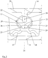
- the structure of the switching chambers 4-6 is similar and is shown on the basis of the enlarged representation of a switching chamber 15 in figure 3 explained further.
- the switching chamber 15 held by the webs 16-18 between the inner casing 19 and the outer casing 20, as well as the webs 17, 18, are formed symmetrically to a central plane 21 through the web 16.
- two opposing switching layers 22, 23 each made of an electrically conductive plastic are introduced as a coextrudate with the first and the second plastic.
- the outer switching layer 22 with respect to the enclosed closing edge is, in the cross section shown, formed like a peg with a rounded contact surface 24.
- the center plane 21 through the pin 16 is perpendicular to the contact surfaces 24,25 of the first and second switching layers 22,23.
- the contact surface 25 of the second switching layer 23 is essentially concave, so that if the switching chamber 15 is deformed, the pin-like outer switching layer 24 can be surrounded by the second switching layer. In order for such an embracing movement to be facilitated are two the peg-like switching layer 24 enclosing notches 26, 27 are introduced into the switching layer 23.
- the safety contact strip 1 is therefore a coextrudate made of two electrically non-conductive plastics, six strands of electrically conductive plastics in the three switching chambers 4-6 with six electrical conductors, which are also coextruded.
- the center planes 10 of the switching chambers 4-6 intersect in the center of the circle spanned by the inner shell 2. Different orientations of the switching chambers 4-6 are possible without any problems.
- the arc of the outer casing 3 is also smaller than that of the inner casing 2.
- the inner casing 2 is in contact with the sections 33, 34 closing the space between the inner casing 2 and the outer casing 3 with two, for example, the fastening of the safety contact strip 1 a post serving flags 35,36, which are provided for easy application of, for example, screws with grooves 37,38 running along the safety contact strip 1.
- Two intermediate walls 39 , 40 are extruded through the first plastic of the outer casing 3 and their cross section tapers towards the inner casing 2 .
- the two switching layers of the switching chambers 4-5 can be connected in series in such a way that if any switching strip 4-5 is loaded and triggered, only a single switching signal is generated. However, it is then not possible to identify the direction from which a load is applied.
- the switching chamber 4 responds, it will detect a load that occurs essentially from the left, the switching chamber 5 will detect a load from the front or from above, and the switching chamber 6 will detect a load from the right. Furthermore, if the front switching chamber 5 and one of the other switching chambers 4.5 respond, a load is applied obliquely from the front.
- the safety contact strip 45 according to figure 2 is profiled in a U-shape in the cross section shown, but corresponds essentially to the safety contact strip 1 according to the technical structure figure 1 .
- the safety contact strip 45 is symmetrical to a central plane 46 which extends in the direction of a linear closing movement of a closing edge bordered by the safety contact strip 45 .
- the safety contact strip 45 also has three switching chambers 47-49, which are each held by three webs 50-52. Due to the roundings 53,54 of the outer shell 55 are the center planes 56 of the webs 50 of the switching chambers 47, 49 perpendicular to the inner surface 57 of the outer casing 55.
- the plastic material of the outer casing 55 also forms the sections 59, 60 which face the closing edge and close the gap between the inner and outer casing 58, 55 and are curved in an S-shape in this exemplary embodiment of a safety contact strip 45.
- Partitions 61 are also formed by the second plastic of the outer jacket 55, in this exemplary embodiment there are four in total, of which a first section 62 adjoining the outer jacket 55 is perpendicular to the inner surface 57. A second section 63 of lesser material thickness adjoins the first section 62 at an angle of incidence, starting from the inner jacket 58 .
- two buffers 65, 66 made from the first plastic of the inner casing 58 also enclose the switching chamber 48.
Landscapes
- Push-Button Switches (AREA)
- Contacts (AREA)
- Power-Operated Mechanisms For Wings (AREA)
- Mechanisms For Operating Contacts (AREA)
Description
- Die Erfindung betrifft eine Sicherheitskontaktleiste für eine Schließkante.
- Sicherheitskontaktleisten werden zum Schutz von Personen und Material regelmäßig an Quetsch- und Scherstellen eingesetzt, beispielsweise an Toren, Türen, Maschinen und Handlingseinrichtungen.
- Eine aus der
WO 2001/044611 A2 bekannte Sicherheitskontaktleiste ist auf einer Befestigungsseite in einem Trägerprofil gehalten, das auf eine Schließkante aufgesetzt werden kann. Diese bekannte Sicherheitskontaktleiste weist zwei elektrisch leitende Schalt-Schichten in einer nichtleitenden, geschlossenen Schaltkammer innerhalb eines äußeren Mantels eines Profils auf, wobei die Schaltkammer in einem Querschnitt von speichenartig ausgebildeten Stegen frei gehalten ist. - Das Profil, die Schaltkammer und die Stege aus einem ersten, nichtleitenden Kunststoff, und die Schalt-Schichten aus einem zweiten, elektrisch leitenden Kunststoff mit jeweils wenigstens einem einbetteten Metall-Leiter sind einstückig durch ein Coextrudat ausgebildet.
- Die aus der
WO 2001/044611 A2 bekannte Sicherheitskontaktleiste schaltet bei einer Berührung sehr sicher, jedoch kann konstruktionsbedingt keine Aussage darüber getroffen werden, aus welcher Richtung eine einen Schaltvorgang auslösende, auf die Sicherheitskontaktleiste einwirkende Kraft kommt. - Solches ist bei der aus der
US 7,282,879 B2 bekannten Sicherheitskontaktleiste möglich. Diese C-förmig oder U-förmig profilierte Sicherheitskontaktleiste kann bspw. die Schließkante eines um eine Achse schwingenden Tores umgreifen und kann durch die Ausbildung von zwei elektrischen Schaltelementen, jeweils in Bewegungsrichtung des Tores orientiert, festgestellt werden, aus welcher Richtung eine einen Schaltvorgang hervorrufende Belastung erfolgt. - Allerdings ist die Ausbildung Sicherheitskontaktleiste insgesamt und insbesondere die der Schaltelemente sehr vielteilig und aufwendig. Daneben ist die Bestimmung der Richtung einer einen Schaltvorgang auslösenden Belastung nur in der Bewegungsrichtung des Tores möglich.
- Vor diesem Hintergrund macht die Erfindung es sich zur Aufgabe, eine exakt schaltende Sicherheitskontaktleiste zur Verfügung zu stellen, die konstruktiv einfach und mechanisch stabil ist.
- Gelöst wird diese technische Problematik durch den Gegenstand des Anspruchs 1. Die Unteransprüche stellen vorteilhafte Weiterbildungen dar.
- Ein Vorteil der Sicherheitskontaktleiste nach der Erfindung besteht darin, dass diese ein einstückiges Coextrudat aus verschiedenen Kunststoffen, sowohl elektrisch isolierenden als auch elektrisch leitenden, und elektrischen Leitern ist.
- Der innere Mantel dient bevorzugt der Anlage und der Befestigung unmittelbar an der Schließkante, gegebenenfalls aber auch einer Befestigung mittels eines Befestigungsprofils, und ist damit weitgehend formstabil. Der von dem inneren Mantel beabstandete, äußere Mantel ist dagegen bei dem Auftreffen auf ein Hindernis deformierbar.
- Mit einer solchen Deformation des äußeren Mantels gegenüber dem im wesentlichen festgelegten inneren Mantel wird, bei ausreichender Größe der Deformation, durch eine oder mehrere Schaltkammern ein Schaltsignal ausgelöst, in dem sich die Schalt-Schichten in einer solchen Kammer gegenseitig berühren.
- In an sich bekannter Weise sind in dem elektrisch leitenden Kunststoff der beiden Schalt-Schichten einer Schaltkammer elektrische Leiter noch eingebettet.
- Bei der Sicherheitskontaktleiste nach der Erfindung sind weiter mehrere Schaltkammern vorgesehen, vorzugsweise drei. Infolge dieser Maßnahme ist es durch die Verschaltung der Schaltkammern möglich, bei Auftreffen auf ein Hindernis ein gemeinsames Signal zu generieren oder mehrere, die, entsprechend ausgewertet, auch eine Aussage über die Richtung der Belastung der Sicherheitskontaktleiste erlauben.
- Dies ist insbesondere zweckmäßig, weil erfindungsgemäß die
Sicherheitskontaktleiste ein die Schließkante umgreifendes Profil aufweist und hierzu L-förmig, C-förmig oder U-förmig profiliert ist, um bspw. auch einen Pfosten zu umgreifen. - Das Ansprechverhalten der Schaltkammern wird im wesentlichen durch deren Aufhängung an den Stegen zwischen dem inneren und dem äußeren Mantel beeinflusst. Es hat sich als zweckmäßig herausgestellt, wenn vorgesehen ist, dass zwischen dem äußeren Mantel und einer Schaltkammer ein einzelner Steg vorgesehen ist, dessen Mittelebene senkrecht auf der Innenfläche des äußeren Mantels steht.
- Vorzugsweise sind dann die Schaltschichten im Wesentlichen senkrecht zu dieser Mittelebene orientiert, so dass die äußere, dem äußeren Mantel benachbarte Schaltschicht bei einer ausreichend steifen Ausbildung dieses Steges dessen Lageänderung bei einer Deformation der Sicherheitskontaktleiste weitgehend folgen wird.
- Infolge dieser Maßnahme wird sich die Position des Anschlusses der Schaltkammer an den äußeren Mantel kaum ändern, während die für einen Schaltvorgang notwendige Deformation der Schaltkammer im wesentlichen gegenüber dem inneren Mantel dann erfolgt.
- Aus diesem Grund ist weiter vorgesehen, dass zwischen dem inneren Mantel und einer Schaltkammer wenigstens ein weiterer Steg vorgesehen ist und dass der einzelne Steg zwischen dem äußeren Mantel und der Schaltkammer gegenüber dem oder den weiteren Stegen zwischen der Schaltkammer und dem inneren Mantel steif ausgebildet ist.
- Der Anschluss der Schaltkammer an den inneren Mantel erfolgt bevorzugt über zwei Stege, die symmetrisch zu einer Mittelebene des einzelnen Steges im nicht deformierten Zustand verlaufen. Hierdurch wird eine Vorzugsrichtung für ein Schalten der Schaltkammer vermieden.
- Neben der Aufhängung der Schaltkammer an den Stegen zwischen dem äußeren und dem inneren Mantel ist die Geometrie der Schalt-Schichten für das exakte Schalten der Sicherheitskontaktleiste nach der Erfindung von Bedeutung.
- So ist vorgesehen, dass einem Querschnitt eine erste, äußere Schaltschicht zapfenartig ausgebildet ist, dass die zweite, innere Schaltschicht eine konkave Kontaktfläche aufweist, in die die erste Schaltschicht eintauchen kann, dass die zweite Schaltschicht die erste Schaltschicht einfassende Einkerbungen aufweist und dass die Mittelebene der ersten Schaltschicht, unbelastet, senkrecht auf zweiten Schaltschicht steht.
- Vorzugsweise ist dabei weiter die erste Schalt-Schicht an ihrem freien Ende abgerundet, so dass eine eher linienförmig sich erstreckende Kontaktfläche ausgebildet wird.
- Die zweite Schalt-Schicht weist eine konkave Berührungsfläche dagegen auf, durch die die zapfenartig ausgebildete erste Schalt-Schicht gleichsam bei einer Deformation der Schaltkammer eingefasst wird. Ein solches Einfassen wird durch die Einkerbungen erleichtert, die in einem gewissen Maße auch eine Deformation der zweiten Schalt-Schicht bei einer Deformation der Schaltkammer erlauben.
- Der äußere und der innere Mantel werden nicht nur durch die von Stegen gehaltenen Schaltkammern voneinander beabstandet gehalten, sondern auch durch Zwischenwände. So ist in konstruktiver Ausgestaltung vorgesehen, dass durch das Coextrudat des zweiten Kunststoffes Zwischenwände zwischen dem äußeren und dem inneren Mantel ausgebildet werden, deren Querschnitt sich hin zu dem inneren Mantel verjüngt. Auch durch diese Maßnahme wird die Deformation der Sicherheitskontaktleiste insgesamt hin zu dem inneren Mantel verlagert.
- Damit, in einem Querschnitt betrachtet, auch im Bereich der links- bzw. rechtseitigen Enden der eine Schließkante einfassenden Sicherheitskontaktleiste ein ausgewogenes Schaltverhalten sichergestellt wird, ist weiter vorgesehen, dass der der Schließkante zugewandte, den Zwischenraum zwischen innerem und äußerem Mantel schließende Abschnitt aus dem Coextrudat des zweiten Kunststoffes S-förmig geschwungen verläuft.
- Eine derartige Ausbildung der Endabschnitte der Sicherheitskontaktleiste nach der Erfindung erlaubt es in einfacher Weise weiter, dass der innere Mantel dem den Zwischenraum zwischen innerem und äußerem Mantel schließende Abschnitt mit einer Fahne vorsteht. Eine solche Fahne dient insbesondere auch dem Festlegen des inneren Mantels an der Schließkante, beispielsweise auch durch Schrauben. Solches ist sehrt einfach, wenn die Fahne mit einer Nut in Längserstreckung der Sicherheitskontaktleiste versehen ist, in der solche Schrauben angesetzt werden können.
- In weiterer konstruktiver Ausgestaltung der
Sicherheitskontaktleiste ist vorgesehen, dass durch das Coextrudat des ersten Kunststoffes zwei dem inneren Mantel vorstehende, eine Schaltkammer einfassende Puffer ausgebildet werden. Dabei ist insbesondere daran gedacht, dass bei einer linearen Schließbewegung der Schließkante eine Schaltkammer zentral vor der Schließkante in Richtung der Schließbewegung angeordnet wird, die von derartigen Puffern eingefasst ist. Bei einem Auftreffen der Sicherheitskontaktleiste bei einem Schließen der Schließkante mit großer Geschwindigkeit auf ein Objekt wird so diese frontseitige Schaltkammer vor einer Beschädigung weitgehend geschützt. - Beispielhaft kann dabei vorgesehen sein, dass der erste Kunststoff eine geringere Shore-Härte aufweist als der zweite Kunststoff, wobei insbesondere daran gedacht ist, dass der erste Kunststoff eine Shore-D-Härte zwischen 30 und 50 aufweist und dass der zweite Kunststoff eine Shore-A-Härte zwischen 35 und 55 aufweist.
- Die Erfindung wird anhand der Zeichnung näher erläutert, in der lediglich zwei bevorzugte Ausführungsbeispiele dargestellt sind. In der Zeichnung zeigt:
- Fig. 1:
- in einem Querschnitt eine C-förmig profilierte Sicherheitskontaktleiste,
- Fig. 2:
- eine U-förmig profilierte Kontaktleiste und
- Fig. 3:
- eine vergrößerte Darstellung einer Schaltkammer.
- Die C-förmig profilierte Sicherheitskontaktleiste 1 gemäß
Figur 1 ist für ein Umgreifen beispielsweise eines runden Endpfostens eines Tores mit runden Querschnitt gedacht. Die Elastizität der verwendeten Kunststoffe erlaubt hierfür eine ausreichende Aufweitung der Öffnung eines inneren Mantels 2. Nach Aufbringen der Sicherheitskontaktleiste 1 auf eine solche Schließkante sollte der innere Mantel 2 jedoch möglichst exakt an der Schließkante anliegen. - Der innere Mantel 2 aus einem ersten elektrisch isolierenden Kunststoff wird von einem äußeren Mantel 3 aus einem zweiten, ebenfalls elektrisch isolierenden Kunststoff in einer koaxialen Anordnung eingefasst. Der innere und der äußere Mantel 2,3 sind ein Coextrudat.
- Zwischen dem inneren und dem äußeren Mantel 2,3 sind bei dem Ausführungsbeispiel drei Schaltkammern 4-6 vorgesehen.
- Jede der Schaltkammern 4-6 ist hier an drei Stegen 7-9 in dem Zwischenraum zwischen dem inneren und dem äußeren Mantel 2,3 gehalten. Der einzelne Steg 7 zwischen dem äußeren Mantel 3 und der Schaltkammer 4 ist vergleichsweise massiv und steif gegenüber den beiden anderen Stegen 8,9 zwischen der Schaltkammer 4 und dem inneren Mantel 2 ausgebildet.
- Die beiden Stege 8,9 zwischen der Schaltkammer 4 und dem inneren Mantel 2 sind symmetrisch zu einer Mittelebene 10 durch den Steg 7 ausgebildet.
- Ausgebildet werden der äußere Mantel 3, die Schaltkammern 4-6 und die Stege 7-9 durch ein Coextrudat eines zweiten elektrisch nichtleitenden Kunststoffes.
- Der Aufbau der Schaltkammern 4-6 ist gleichartig und wird anhand der vergrößerten Darstellung einer Schaltkammer 15 in
Figur 3 weiter erläutert. - Die von den Stegen 16-18 zwischen dem inneren Mantel 19 und dem äußeren Mantel 20 gehaltene Schaltkammer 15 wie auch die Stege 17,18 sind zu einer Mittelebene 21 durch den Steg 16 symmetrisch ausgebildet.
- In der Schaltkammer 15 sind zwei sich gegenüberliegende Schalt-Schichten 22,23 aus jeweils einem elektrisch leitenden Kunststoff als Coextrudat mit dem ersten und dem zweiten Kunststoff eingebracht. Die mit Bezug auf die umgriffene Schließkante äußere Schalt-Schicht 22 ist, in dem wiedergegebenen Querschnitt, zapfenartig ausgebildet mit einer abgerundeten Kontaktfläche 24.
- Die Mittelebene 21 durch den Zapfen 16 steht senkrecht auf den Kontaktflächen 24,25 der ersten und zweiten Schalt-Schicht 22,23. Die Kontaktfläche 25 der zweiten Schalt-Schicht 23 ist im wesentlichen konkav ausgebildet, so dass bei einer Deformation der Schaltkammer 15 die zapfenartig ausgebildete äußere Schalt-Schicht 24 gleichsam von der zweiten Schaltschicht eingefasst werden kann. Damit eine solche einfassende Bewegung erleichtert wird, sind zwei die zapfenartige Schalt-Schicht 24 einfassende Einkerbungen 26,27 in die Schalt-Schicht 23 noch eingebracht.
- In die beiden Schalt-Schichten 22,23 sind noch zwei elektrische Leiter 28,29 eingebracht.
- Die Sicherheitskontaktleiste 1 stellt sich demnach als ein Coextrudat aus zwei elektrisch nichtleitenden Kunststoffen, sechs Strängen elektrisch leitender Kunststoffe in den drei Schaltkammern 4-6 mit ebenfalls coextrudierten, sechs elektrischen Leitern dar.
- Bei dem Ausführungsbeispiel der Sicherheitskontaktleiste 1 gemäß
Figur 1 schneiden sich die Mittelebenen 10 der Schaltkammern 4-6 im Mittelpunkt des von dem inneren Mantel 2 aufgespannten Kreises. Hiervon abweichende Orientierungen der Schaltkammern 4-6 sind problemlos möglich. - Bei dem Ausführungsbeispiel der Sicherheitskontaktleiste 1 nach
Figur 1 ist weiter der Bogen des äußeren Mantels 3 geringer bemessen als der des inneren Mantels 2. Infolgedessen steht der innere Mantel 2 den den Zwischenraum zwischen dem inneren Mantel 2 und dem äußeren Mantel 3 schließenden Abschnitten 33,34 mit zwei beispielsweise der Befestigung der Sicherheitskontaktleiste 1 an einem Pfosten dienende Fahnen 35,36 vor, die für ein leichtes Ansetzen von bspw. Schrauben mit längs der Sicherheitskontaktleiste 1 verlaufenden Nuten 37,38 versehen sind. - Durch den ersten Kunststoff des äußeren Mantels 3 werden zwei Zwischenwände 39,40 noch extrudiert, die sich hin zu dem inneren Mantel 2 in einem Querschnitt verjüngen.
- Durch den ersten Kunststoff des inneren Mantels 2 werden ferner zwei Puffer 41,42 ausgebildet, die bei einer größeren
- Deformation der Sicherheitskontaktleiste bei einer linearen Bewegung entlang der Symmetrieebene der Sicherheitskontaktleiste 1 und Mittelebene 43 der Schaltkammer 5 diese einfassen und schützen.
- Die zwei Schaltschichten der Schaltkammern 4-5 können derart in Reihe geschaltete werden, dass bei einer Belastung und Auslösung einer beliebigen Schaltleiste 4-5 nur ein einziges Schaltsignal generiert wird. Ein Erkennen der Richtung, aus der eine Belastung erfolgt, ist dann jedoch nicht möglich.
- Alternativ ist jedoch auch eine Bestimmung der Richtung möglich, aus der eine Belastung der Sicherheitskontaktleiste 1 erfolgt. Mit Bezug auf
Fig. 1 wird das Ansprechen der Schaltkammer 4 eine im Wesentlichen von links erfolgende Belastung detektieren, die Schaltkammer 5 eine von vorn bzw. von oben und die Schaltkammer 6 eine von rechts. Sprechen ferner die vordere Schaltkammer 5 und eine der weiteren Schaltkammer 4,5 an, so erfolgt eine Belastung von schräg vorne. - Die Sicherheitskontaktleiste 45 gemäß
Figur 2 ist in dem wiedergegebenen Querschnitt U-förmig profiliert, entspricht aber in dem technischen Aufbau im wesentlichen der Sicherheitskontaktleiste 1 gemäßFigur 1 . So ist die Sicherheitskontaktleiste 45 wie die Sicherheitskontaktleiste 1 symmetrisch zu einer Mittelebene 46, die sich in Richtung einer linearen Schließbewegung eines von der Sicherheitskontaktleiste 45 einfassten Schließkante erstreckt. - Auch die Sicherheitskontaktleiste 45 weist drei Schaltkammern 47-49 auf, die jeweils von drei Stegen 50-52 gehalten sind. Aufgrund der Abrundungen 53,54 des äußeren Mantels 55 stehen die Mittelebenen 56 der Stege 50 der Schaltkammern 47,49 senkrecht auf der Innenfläche 57 des äußeren Mantels 55.
- Durch das Kunststoffmaterial des äußeren Mantels 55 werden auch die der Schließkante zugewandten, den Zwischenraum zwischen innerem und äußerem Mantel 58,55 schließenden Abschnitte 59,60 ausgebildet, die bei diesem Ausführungsbeispiel einer Sicherheitskontaktleiste 45 S-förmig geschwungen sind.
- Ebenfalls durch den zweiten Kunststoff des äußeren Mantels 55 werden Zwischenwände 61 ausgebildet, bei diesem Ausführungsbeispiel insgesamt vier Stück, von denen ein erster, an den äußeren Mantel 55 anschließender Abschnitt 62 auf der Innenfläche 57 senkrecht steht. Ein zweiter Abschnitt 63 geringerer Materialstärke schließt ausgehend von dem inneren Mantel 58 unter einem Anstellwinkel an den ersten Abschnitt 62 an.
- Entsprechend dem ersten Ausführungsbeispiel einer Sicherheitskontaktleiste 1 fassen weiter zwei Puffer 65,66 aus dem ersten Kunststoff des inneren Mantels 58 die Schaltkammer 48 ein.
- Für eine Befestigung an einer Schließkante weisen die den Abschnitten 59,60 vorstehenden Fahnen 67,68 des inneren Mantels 58 wie das erste Ausführungsbeispiel noch längs der Sicherheitskontaktleiste 45 verlaufende Nuten 69,70 noch auf.
Claims (13)
- In einem Querschnitt L-, C- oder U-förmig profilierte Sicherheitskontaktleiste für zumindest ein teilweises Umgreifen einer Schließkante, wobei durch ein Coextrudat eines ersten elektrisch isolierenden Kunststoffes ein der Schließkante zugewandter, innerer Mantel (2) ausgebildet wird, wobei beabstandet von dem inneren Mantel (2) durch ein Coextrudat eines zweiten elektrisch isolierenden Kunststoffes ein äußerer Mantel (3) ausgebildet wird, wobei mit dem äußeren Mantel (3) mehrere von jeweils wenigstens einem Steg (7-9) zwischen dem inneren und äußeren Mantel (2,3) gehaltene Schaltkammern (4-6) ausgebildet werden, wobei durch ein Coextrudat eines dritten elektrisch leitenden Kunststoffes in jeder Schaltkammer (15) zwei voneinander beabstandete Schaltschichten (22,23) ausgebildet werden und wobei als weitere Coextrudate in den Schaltschichten (22,23) jeweils ein elektrischer Leiter (28,29) eingebettet ist.
- Sicherheitskontaktleiste nach Anspruch 1, dadurch gekennzeichnet, dass durch die Verschaltung der Schaltkammern (4-6) bei Auftreffen auf ein Hindernis ein gemeinsames Signal generiert wird oder dass eine Auswertung der einzelnen Signale der Schaltkammern (4-6) bei Auftreffen auf ein Hindernis eine Aussage über die Richtung der Belastung der Sicherheitskontaktleiste (1,45) erlaubt.
- Sicherheitskontaktleiste nach einem oder mehreren der vorangehenden Ansprüche, dadurch gekennzeichnet, dass die Sicherheitskontaktleiste (1,45) ein die Schließkante umgreifendes Profil aufweist.
- Sicherheitskontaktleiste nach einem oder mehreren der vorangehenden Ansprüche, dadurch gekennzeichnet, dass zwischen dem äußeren Mantel (20) und einer Schaltkammer (15) ein einzelner Steg (16) vorgesehen ist, dessen Mittelebene (21) senkrecht auf der Innenfläche des äußeren Mantels (20) steht.
- Sicherheitskontaktleiste nach einem oder mehreren der vorangehenden Ansprüche, dadurch gekennzeichnet, dass zwischen dem inneren Mantel (19) und einer Schaltkammer (15) wenigstens ein weiterer Steg (17,18) vorgesehen ist und dass der einzelne Steg (16) zwischen dem äußeren Mantel (20) und der Schaltkammer (15) gegenüber dem oder den weiteren Stegen (17,18) zwischen der Schaltkammer (15) und dem inneren Mantel (19) steif ausgebildet ist.
- Sicherheitskontaktleiste nach einem oder mehreren der vorangehenden Ansprüche, dadurch gekennzeichnet, dass in einem Querschnitt eine erste, äußere Schaltschicht (22) zapfenartig ausgebildet ist, dass die zweite, innere Schaltschicht (23) eine konkave Kontaktfläche (25) aufweist, in die die erste Schaltschicht (22) eintauchen kann, dass die zweite Schaltschicht (23) die erste Schaltschicht (22) einfassende Einkerbungen (26,27) aufweist und dass die Mittelebene (21) der ersten Schaltschicht (22), unbelastet, senkrecht auf der zweiten Schaltschicht (23) steht.
- Sicherheitskontaktleiste nach einem oder mehreren der vorangehenden Ansprüche, dadurch gekennzeichnet, dass durch das Coextrudat des zweiten Kunststoffes Zwischenwände (39,40) zwischen dem äußeren und dem inneren Mantel (3,2) ausgebildet werden, die sich in einem Querschnitt hin zu dem inneren Mantel (2) verjüngen.
- Sicherheitskontaktleiste nach einem oder mehreren der vorangehenden Ansprüche, dadurch gekennzeichnet, dass der der Schließkante zugewandte, den Zwischenraum zwischen innerem und äußerem Mantel (58,55) schließende Abschnitt (59,60) aus dem Coextrudat des zweiten Kunststoffes S-förmig geschwungen verläuft.
- Sicherheitskontaktleiste nach einem oder mehreren der vorangehenden Ansprüche, dadurch gekennzeichnet, dass der innere Mantel (2) dem den Zwischenraum zwischen innerem und äußerem Mantel (2,3) schließende Abschnitt (33,34) mit einer Fahne (35,36) vorsteht.
- Sicherheitskontaktleiste nach Anspruch 9, dadurch gekennzeichnet, dass die Fahne (35,36) mit einer Nut (37,38) in Längserstreckung der Sicherheitskontaktleiste (1) versehen ist.
- Sicherheitskontaktleiste nach einem oder mehreren der vorangehenden Ansprüche, dadurch gekennzeichnet, dass durch das Coextrudat des ersten Kunststoffes zwei dem inneren Mantel (2) vorstehende, eine Schaltkammer (5) einfassende Puffer (41,42) ausgebildet werden.
- Sicherheitskontaktleiste nach einem oder mehreren der vorangehenden Ansprüche, dadurch gekennzeichnet, dass der erste Kunststoff eine geringere Shore-Härte aufweist als der zweite Kunststoff.
- Sicherheitskontaktleiste nach einem oder mehreren der vorangehenden Ansprüche, dadurch gekennzeichnet, dass der erste Kunststoff eine Shore-D-Härte zwischen 30 und 50 aufweist und dass der zweite Kunststoff eine Shore-A-Härte zwischen 35 und 55 aufweist.
Applications Claiming Priority (2)
| Application Number | Priority Date | Filing Date | Title |
|---|---|---|---|
| DE102017005514.9A DE102017005514A1 (de) | 2017-06-12 | 2017-06-12 | Sicherheitskontaktleiste |
| PCT/DE2018/000110 WO2018228620A1 (de) | 2017-06-12 | 2018-04-23 | Sicherheitskontaktleiste |
Publications (2)
| Publication Number | Publication Date |
|---|---|
| EP3638868A1 EP3638868A1 (de) | 2020-04-22 |
| EP3638868B1 true EP3638868B1 (de) | 2022-06-08 |
Family
ID=62455280
Family Applications (1)
| Application Number | Title | Priority Date | Filing Date |
|---|---|---|---|
| EP18728010.2A Active EP3638868B1 (de) | 2017-06-12 | 2018-04-23 | Sicherheitskontaktleiste |
Country Status (9)
| Country | Link |
|---|---|
| US (1) | US11078707B2 (de) |
| EP (1) | EP3638868B1 (de) |
| JP (1) | JP2020524368A (de) |
| CN (1) | CN110621842A (de) |
| CA (1) | CA3066183A1 (de) |
| DE (1) | DE102017005514A1 (de) |
| ES (1) | ES2925325T3 (de) |
| PL (1) | PL3638868T3 (de) |
| WO (1) | WO2018228620A1 (de) |
Families Citing this family (2)
| Publication number | Priority date | Publication date | Assignee | Title |
|---|---|---|---|---|
| ES3010119T3 (en) * | 2017-09-19 | 2025-04-01 | Knorr Bremse Gmbh | Device for protection against entrapment for a door for a vehicle, door system for a vehicle and method for producing a device for protection against entrapment for a door for a vehicle |
| JP6516052B1 (ja) * | 2018-06-25 | 2019-05-22 | 日立金属株式会社 | 挟み込み検知センサ |
Family Cites Families (14)
| Publication number | Priority date | Publication date | Assignee | Title |
|---|---|---|---|---|
| US3118984A (en) * | 1961-04-12 | 1964-01-21 | Tapeswitch Corp Of America | Door edge switch means |
| DE3232365C2 (de) * | 1982-08-31 | 1986-07-10 | Erwin Sick Gmbh Optik-Elektronik, 7808 Waldkirch | Elastisches Profil an der Schließkante einer Abdeckung |
| EP0104414B1 (de) | 1982-08-31 | 1987-05-06 | Erwin Sick GmbH Optik-Elektronik | Längliches, elastisches Türkantenprofil |
| DE8713426U1 (de) * | 1987-10-06 | 1987-11-26 | Huber & Suhner AG, Pfäffikon | Klemmschutzleistenprofil |
| DE29808292U1 (de) * | 1998-05-07 | 1998-07-23 | Schieffer Tor- und Schutzsysteme GmbH, 59557 Lippstadt | Abschlußprofil für ein Torblatt |
| DE29921958U1 (de) | 1999-12-16 | 2001-04-26 | ASO GmbH Antriebs- und Steuerungstechnik, 33154 Salzkotten | Sicherheitskontaktleiste |
| DE10155466A1 (de) * | 2001-11-12 | 2003-05-22 | Karlheinz Beckhausen | Schließkantensicherheitsprofil |
| EP1861838A4 (de) | 2005-02-16 | 2013-05-15 | Miller Edge Inc | Bidirektionale messkante für ein gate |
| JP5158038B2 (ja) * | 2009-08-31 | 2013-03-06 | 豊田合成株式会社 | 長尺センサ |
| US9234979B2 (en) * | 2009-12-08 | 2016-01-12 | Magna Closures Inc. | Wide activation angle pinch sensor section |
| US8493081B2 (en) * | 2009-12-08 | 2013-07-23 | Magna Closures Inc. | Wide activation angle pinch sensor section and sensor hook-on attachment principle |
| JP6317144B2 (ja) * | 2014-03-18 | 2018-04-25 | 西川ゴム工業株式会社 | センサー付きプロテクター |
| JP6424074B2 (ja) * | 2014-11-21 | 2018-11-14 | 西川ゴム工業株式会社 | センサー付きプロテクター |
| JP6516052B1 (ja) * | 2018-06-25 | 2019-05-22 | 日立金属株式会社 | 挟み込み検知センサ |
-
2017
- 2017-06-12 DE DE102017005514.9A patent/DE102017005514A1/de not_active Withdrawn
-
2018
- 2018-04-23 JP JP2019569723A patent/JP2020524368A/ja not_active Ceased
- 2018-04-23 CA CA3066183A patent/CA3066183A1/en active Pending
- 2018-04-23 CN CN201880031691.8A patent/CN110621842A/zh active Pending
- 2018-04-23 EP EP18728010.2A patent/EP3638868B1/de active Active
- 2018-04-23 US US16/621,984 patent/US11078707B2/en active Active
- 2018-04-23 ES ES18728010T patent/ES2925325T3/es active Active
- 2018-04-23 PL PL18728010.2T patent/PL3638868T3/pl unknown
- 2018-04-23 WO PCT/DE2018/000110 patent/WO2018228620A1/de not_active Ceased
Also Published As
| Publication number | Publication date |
|---|---|
| CA3066183A1 (en) | 2018-12-20 |
| EP3638868A1 (de) | 2020-04-22 |
| ES2925325T3 (es) | 2022-10-17 |
| CN110621842A (zh) | 2019-12-27 |
| PL3638868T3 (pl) | 2022-09-26 |
| US11078707B2 (en) | 2021-08-03 |
| US20200149337A1 (en) | 2020-05-14 |
| DE102017005514A1 (de) | 2018-12-13 |
| JP2020524368A (ja) | 2020-08-13 |
| WO2018228620A1 (de) | 2018-12-20 |
Similar Documents
| Publication | Publication Date | Title |
|---|---|---|
| EP3348979B1 (de) | Taktiler sensor mit gehäuse | |
| EP2371062B1 (de) | Kapazitiver annäherungssensor mit einer schirmelektrode und einer diagnoseelektrode | |
| DE102008028278A1 (de) | Vorrichtung zum Hindurchführen und Halten von Kabeln oder sonstigen Strängen | |
| DE102017208957A1 (de) | Türhebel und Antenneneinheit | |
| EP3348980A1 (de) | Mehrschichtiger, taktiler sensor mit befestigungsmittel | |
| EP3847332B1 (de) | Schutzvorrichtung für einen türflügel für ein fahrzeug und türvorrichtung für ein fahrzeug | |
| DE3232365C2 (de) | Elastisches Profil an der Schließkante einer Abdeckung | |
| WO2018228620A1 (de) | Sicherheitskontaktleiste | |
| EP2859658B1 (de) | Kapazitive sensoranordnung zur schaltung einer türöffnung an einem kraftfahrzeug | |
| EP2009292B1 (de) | Pneumatikzylinder mit einem Zylindergehäuse aus stranggepresstem Metall | |
| EP1310624B1 (de) | Schliesskantensicherheitsprofil | |
| EP1568833A2 (de) | Schliessblech für ein Fenster oder eine Tür | |
| DE102006053572B3 (de) | Kapazitiver Sensor, insbesondere für eine Einrichtung zum Einklemmschutz an einem Kraftfahrzeug | |
| DE2458652C3 (de) | Elektrische Alarmvorrichtung für eine schließzylinderbetätigte Verriegelungsvorrichtung | |
| DE102008026598A1 (de) | Schalter zum Unterbrechen eines mit Strom beaufschlagbaren Kabels | |
| WO1988004129A1 (fr) | Boitier blinde | |
| DE10300866A1 (de) | Schaltelement | |
| DE9215377U1 (de) | Sensor zur Detektierung von Fahrzeugunfällen | |
| EP3482407B1 (de) | Schliesskanten-sicherung mit vorkammer | |
| EP2553190B1 (de) | Schutzeinrichtung für ein schloss gegen manipulation des schlosses | |
| EP2143865B1 (de) | Objektschutztür | |
| EP1020608B2 (de) | Verbundprofil für Rahmen von Wandelementen, Türen und Fenstern | |
| DE9115266U1 (de) | Öffnungsmelder | |
| EP2774796B1 (de) | Elastisches Hohlprofil | |
| EP1396600A2 (de) | Schaltelement |
Legal Events
| Date | Code | Title | Description |
|---|---|---|---|
| STAA | Information on the status of an ep patent application or granted ep patent |
Free format text: STATUS: UNKNOWN |
|
| STAA | Information on the status of an ep patent application or granted ep patent |
Free format text: STATUS: THE INTERNATIONAL PUBLICATION HAS BEEN MADE |
|
| PUAI | Public reference made under article 153(3) epc to a published international application that has entered the european phase |
Free format text: ORIGINAL CODE: 0009012 |
|
| STAA | Information on the status of an ep patent application or granted ep patent |
Free format text: STATUS: REQUEST FOR EXAMINATION WAS MADE |
|
| 17P | Request for examination filed |
Effective date: 20191119 |
|
| AK | Designated contracting states |
Kind code of ref document: A1 Designated state(s): AL AT BE BG CH CY CZ DE DK EE ES FI FR GB GR HR HU IE IS IT LI LT LU LV MC MK MT NL NO PL PT RO RS SE SI SK SM TR |
|
| AX | Request for extension of the european patent |
Extension state: BA ME |
|
| DAV | Request for validation of the european patent (deleted) | ||
| DAX | Request for extension of the european patent (deleted) | ||
| GRAP | Despatch of communication of intention to grant a patent |
Free format text: ORIGINAL CODE: EPIDOSNIGR1 |
|
| STAA | Information on the status of an ep patent application or granted ep patent |
Free format text: STATUS: GRANT OF PATENT IS INTENDED |
|
| INTG | Intention to grant announced |
Effective date: 20211004 |
|
| GRAS | Grant fee paid |
Free format text: ORIGINAL CODE: EPIDOSNIGR3 |
|
| GRAJ | Information related to disapproval of communication of intention to grant by the applicant or resumption of examination proceedings by the epo deleted |
Free format text: ORIGINAL CODE: EPIDOSDIGR1 |
|
| GRAL | Information related to payment of fee for publishing/printing deleted |
Free format text: ORIGINAL CODE: EPIDOSDIGR3 |
|
| STAA | Information on the status of an ep patent application or granted ep patent |
Free format text: STATUS: REQUEST FOR EXAMINATION WAS MADE |
|
| INTC | Intention to grant announced (deleted) | ||
| GRAP | Despatch of communication of intention to grant a patent |
Free format text: ORIGINAL CODE: EPIDOSNIGR1 |
|
| STAA | Information on the status of an ep patent application or granted ep patent |
Free format text: STATUS: GRANT OF PATENT IS INTENDED |
|
| INTG | Intention to grant announced |
Effective date: 20220324 |
|
| RIN1 | Information on inventor provided before grant (corrected) |
Inventor name: STROOP, HUBERT Inventor name: KLAUSE, NICK Inventor name: FRIEDRICH, HELMUT |
|
| GRAA | (expected) grant |
Free format text: ORIGINAL CODE: 0009210 |
|
| STAA | Information on the status of an ep patent application or granted ep patent |
Free format text: STATUS: THE PATENT HAS BEEN GRANTED |
|
| AK | Designated contracting states |
Kind code of ref document: B1 Designated state(s): AL AT BE BG CH CY CZ DE DK EE ES FI FR GB GR HR HU IE IS IT LI LT LU LV MC MK MT NL NO PL PT RO RS SE SI SK SM TR |
|
| REG | Reference to a national code |
Ref country code: AT Ref legal event code: REF Ref document number: 1497040 Country of ref document: AT Kind code of ref document: T Effective date: 20220615 Ref country code: CH Ref legal event code: EP |
|
| REG | Reference to a national code |
Ref country code: DE Ref legal event code: R096 Ref document number: 502018009881 Country of ref document: DE |
|
| REG | Reference to a national code |
Ref country code: IE Ref legal event code: FG4D Free format text: LANGUAGE OF EP DOCUMENT: GERMAN |
|
| REG | Reference to a national code |
Ref country code: LT Ref legal event code: MG9D |
|
| REG | Reference to a national code |
Ref country code: NL Ref legal event code: MP Effective date: 20220608 |
|
| REG | Reference to a national code |
Ref country code: ES Ref legal event code: FG2A Ref document number: 2925325 Country of ref document: ES Kind code of ref document: T3 Effective date: 20221017 |
|
| PG25 | Lapsed in a contracting state [announced via postgrant information from national office to epo] |
Ref country code: SE Free format text: LAPSE BECAUSE OF FAILURE TO SUBMIT A TRANSLATION OF THE DESCRIPTION OR TO PAY THE FEE WITHIN THE PRESCRIBED TIME-LIMIT Effective date: 20220608 Ref country code: NO Free format text: LAPSE BECAUSE OF FAILURE TO SUBMIT A TRANSLATION OF THE DESCRIPTION OR TO PAY THE FEE WITHIN THE PRESCRIBED TIME-LIMIT Effective date: 20220908 Ref country code: LT Free format text: LAPSE BECAUSE OF FAILURE TO SUBMIT A TRANSLATION OF THE DESCRIPTION OR TO PAY THE FEE WITHIN THE PRESCRIBED TIME-LIMIT Effective date: 20220608 Ref country code: HR Free format text: LAPSE BECAUSE OF FAILURE TO SUBMIT A TRANSLATION OF THE DESCRIPTION OR TO PAY THE FEE WITHIN THE PRESCRIBED TIME-LIMIT Effective date: 20220608 Ref country code: GR Free format text: LAPSE BECAUSE OF FAILURE TO SUBMIT A TRANSLATION OF THE DESCRIPTION OR TO PAY THE FEE WITHIN THE PRESCRIBED TIME-LIMIT Effective date: 20220909 Ref country code: FI Free format text: LAPSE BECAUSE OF FAILURE TO SUBMIT A TRANSLATION OF THE DESCRIPTION OR TO PAY THE FEE WITHIN THE PRESCRIBED TIME-LIMIT Effective date: 20220608 Ref country code: BG Free format text: LAPSE BECAUSE OF FAILURE TO SUBMIT A TRANSLATION OF THE DESCRIPTION OR TO PAY THE FEE WITHIN THE PRESCRIBED TIME-LIMIT Effective date: 20220908 |
|
| PG25 | Lapsed in a contracting state [announced via postgrant information from national office to epo] |
Ref country code: RS Free format text: LAPSE BECAUSE OF FAILURE TO SUBMIT A TRANSLATION OF THE DESCRIPTION OR TO PAY THE FEE WITHIN THE PRESCRIBED TIME-LIMIT Effective date: 20220608 Ref country code: LV Free format text: LAPSE BECAUSE OF FAILURE TO SUBMIT A TRANSLATION OF THE DESCRIPTION OR TO PAY THE FEE WITHIN THE PRESCRIBED TIME-LIMIT Effective date: 20220608 |
|
| PG25 | Lapsed in a contracting state [announced via postgrant information from national office to epo] |
Ref country code: NL Free format text: LAPSE BECAUSE OF FAILURE TO SUBMIT A TRANSLATION OF THE DESCRIPTION OR TO PAY THE FEE WITHIN THE PRESCRIBED TIME-LIMIT Effective date: 20220608 |
|
| PG25 | Lapsed in a contracting state [announced via postgrant information from national office to epo] |
Ref country code: SM Free format text: LAPSE BECAUSE OF FAILURE TO SUBMIT A TRANSLATION OF THE DESCRIPTION OR TO PAY THE FEE WITHIN THE PRESCRIBED TIME-LIMIT Effective date: 20220608 Ref country code: SK Free format text: LAPSE BECAUSE OF FAILURE TO SUBMIT A TRANSLATION OF THE DESCRIPTION OR TO PAY THE FEE WITHIN THE PRESCRIBED TIME-LIMIT Effective date: 20220608 Ref country code: RO Free format text: LAPSE BECAUSE OF FAILURE TO SUBMIT A TRANSLATION OF THE DESCRIPTION OR TO PAY THE FEE WITHIN THE PRESCRIBED TIME-LIMIT Effective date: 20220608 Ref country code: PT Free format text: LAPSE BECAUSE OF FAILURE TO SUBMIT A TRANSLATION OF THE DESCRIPTION OR TO PAY THE FEE WITHIN THE PRESCRIBED TIME-LIMIT Effective date: 20221010 Ref country code: EE Free format text: LAPSE BECAUSE OF FAILURE TO SUBMIT A TRANSLATION OF THE DESCRIPTION OR TO PAY THE FEE WITHIN THE PRESCRIBED TIME-LIMIT Effective date: 20220608 Ref country code: CZ Free format text: LAPSE BECAUSE OF FAILURE TO SUBMIT A TRANSLATION OF THE DESCRIPTION OR TO PAY THE FEE WITHIN THE PRESCRIBED TIME-LIMIT Effective date: 20220608 |
|
| PG25 | Lapsed in a contracting state [announced via postgrant information from national office to epo] |
Ref country code: IS Free format text: LAPSE BECAUSE OF FAILURE TO SUBMIT A TRANSLATION OF THE DESCRIPTION OR TO PAY THE FEE WITHIN THE PRESCRIBED TIME-LIMIT Effective date: 20221008 |
|
| REG | Reference to a national code |
Ref country code: DE Ref legal event code: R097 Ref document number: 502018009881 Country of ref document: DE |
|
| PG25 | Lapsed in a contracting state [announced via postgrant information from national office to epo] |
Ref country code: AL Free format text: LAPSE BECAUSE OF FAILURE TO SUBMIT A TRANSLATION OF THE DESCRIPTION OR TO PAY THE FEE WITHIN THE PRESCRIBED TIME-LIMIT Effective date: 20220608 |
|
| PLBE | No opposition filed within time limit |
Free format text: ORIGINAL CODE: 0009261 |
|
| STAA | Information on the status of an ep patent application or granted ep patent |
Free format text: STATUS: NO OPPOSITION FILED WITHIN TIME LIMIT |
|
| PG25 | Lapsed in a contracting state [announced via postgrant information from national office to epo] |
Ref country code: DK Free format text: LAPSE BECAUSE OF FAILURE TO SUBMIT A TRANSLATION OF THE DESCRIPTION OR TO PAY THE FEE WITHIN THE PRESCRIBED TIME-LIMIT Effective date: 20220608 |
|
| 26N | No opposition filed |
Effective date: 20230310 |
|
| PG25 | Lapsed in a contracting state [announced via postgrant information from national office to epo] |
Ref country code: SI Free format text: LAPSE BECAUSE OF FAILURE TO SUBMIT A TRANSLATION OF THE DESCRIPTION OR TO PAY THE FEE WITHIN THE PRESCRIBED TIME-LIMIT Effective date: 20220608 |
|
| PG25 | Lapsed in a contracting state [announced via postgrant information from national office to epo] |
Ref country code: LU Free format text: LAPSE BECAUSE OF NON-PAYMENT OF DUE FEES Effective date: 20230423 |
|
| REG | Reference to a national code |
Ref country code: BE Ref legal event code: MM Effective date: 20230430 |
|
| PG25 | Lapsed in a contracting state [announced via postgrant information from national office to epo] |
Ref country code: MC Free format text: LAPSE BECAUSE OF FAILURE TO SUBMIT A TRANSLATION OF THE DESCRIPTION OR TO PAY THE FEE WITHIN THE PRESCRIBED TIME-LIMIT Effective date: 20220608 |
|
| PG25 | Lapsed in a contracting state [announced via postgrant information from national office to epo] |
Ref country code: MC Free format text: LAPSE BECAUSE OF FAILURE TO SUBMIT A TRANSLATION OF THE DESCRIPTION OR TO PAY THE FEE WITHIN THE PRESCRIBED TIME-LIMIT Effective date: 20220608 |
|
| REG | Reference to a national code |
Ref country code: IE Ref legal event code: MM4A |
|
| PG25 | Lapsed in a contracting state [announced via postgrant information from national office to epo] |
Ref country code: BE Free format text: LAPSE BECAUSE OF NON-PAYMENT OF DUE FEES Effective date: 20230430 |
|
| PG25 | Lapsed in a contracting state [announced via postgrant information from national office to epo] |
Ref country code: IE Free format text: LAPSE BECAUSE OF NON-PAYMENT OF DUE FEES Effective date: 20230423 |
|
| PG25 | Lapsed in a contracting state [announced via postgrant information from national office to epo] |
Ref country code: IE Free format text: LAPSE BECAUSE OF NON-PAYMENT OF DUE FEES Effective date: 20230423 |
|
| PGFP | Annual fee paid to national office [announced via postgrant information from national office to epo] |
Ref country code: GB Payment date: 20240409 Year of fee payment: 7 |
|
| PGFP | Annual fee paid to national office [announced via postgrant information from national office to epo] |
Ref country code: DE Payment date: 20240410 Year of fee payment: 7 |
|
| PGFP | Annual fee paid to national office [announced via postgrant information from national office to epo] |
Ref country code: CH Payment date: 20240501 Year of fee payment: 7 |
|
| PGFP | Annual fee paid to national office [announced via postgrant information from national office to epo] |
Ref country code: ES Payment date: 20240508 Year of fee payment: 7 |
|
| PGFP | Annual fee paid to national office [announced via postgrant information from national office to epo] |
Ref country code: AT Payment date: 20240409 Year of fee payment: 7 |
|
| PGFP | Annual fee paid to national office [announced via postgrant information from national office to epo] |
Ref country code: IT Payment date: 20240424 Year of fee payment: 7 Ref country code: FR Payment date: 20240425 Year of fee payment: 7 |
|
| PGFP | Annual fee paid to national office [announced via postgrant information from national office to epo] |
Ref country code: PL Payment date: 20240409 Year of fee payment: 7 |
|
| PG25 | Lapsed in a contracting state [announced via postgrant information from national office to epo] |
Ref country code: BG Free format text: LAPSE BECAUSE OF FAILURE TO SUBMIT A TRANSLATION OF THE DESCRIPTION OR TO PAY THE FEE WITHIN THE PRESCRIBED TIME-LIMIT Effective date: 20220608 |
|
| PG25 | Lapsed in a contracting state [announced via postgrant information from national office to epo] |
Ref country code: BG Free format text: LAPSE BECAUSE OF FAILURE TO SUBMIT A TRANSLATION OF THE DESCRIPTION OR TO PAY THE FEE WITHIN THE PRESCRIBED TIME-LIMIT Effective date: 20220608 |
|
| PG25 | Lapsed in a contracting state [announced via postgrant information from national office to epo] |
Ref country code: CY Free format text: LAPSE BECAUSE OF FAILURE TO SUBMIT A TRANSLATION OF THE DESCRIPTION OR TO PAY THE FEE WITHIN THE PRESCRIBED TIME-LIMIT; INVALID AB INITIO Effective date: 20180423 |
|
| PG25 | Lapsed in a contracting state [announced via postgrant information from national office to epo] |
Ref country code: HU Free format text: LAPSE BECAUSE OF FAILURE TO SUBMIT A TRANSLATION OF THE DESCRIPTION OR TO PAY THE FEE WITHIN THE PRESCRIBED TIME-LIMIT; INVALID AB INITIO Effective date: 20180423 |
|
| REG | Reference to a national code |
Ref country code: DE Ref legal event code: R119 Ref document number: 502018009881 Country of ref document: DE |
|
| REG | Reference to a national code |
Ref country code: CH Ref legal event code: H13 Free format text: ST27 STATUS EVENT CODE: U-0-0-H10-H13 (AS PROVIDED BY THE NATIONAL OFFICE) Effective date: 20251125 |
|
| PG25 | Lapsed in a contracting state [announced via postgrant information from national office to epo] |
Ref country code: TR Free format text: LAPSE BECAUSE OF FAILURE TO SUBMIT A TRANSLATION OF THE DESCRIPTION OR TO PAY THE FEE WITHIN THE PRESCRIBED TIME-LIMIT Effective date: 20220608 |
|
| REG | Reference to a national code |
Ref country code: AT Ref legal event code: MM01 Ref document number: 1497040 Country of ref document: AT Kind code of ref document: T Effective date: 20250423 |
|
| GBPC | Gb: european patent ceased through non-payment of renewal fee |
Effective date: 20250423 |
|
| PG25 | Lapsed in a contracting state [announced via postgrant information from national office to epo] |
Ref country code: DE Free format text: LAPSE BECAUSE OF NON-PAYMENT OF DUE FEES Effective date: 20251104 |
|
| PG25 | Lapsed in a contracting state [announced via postgrant information from national office to epo] |
Ref country code: GB Free format text: LAPSE BECAUSE OF NON-PAYMENT OF DUE FEES Effective date: 20250423 |
|
| PG25 | Lapsed in a contracting state [announced via postgrant information from national office to epo] |
Ref country code: AT Free format text: LAPSE BECAUSE OF NON-PAYMENT OF DUE FEES Effective date: 20250423 |
|
| PG25 | Lapsed in a contracting state [announced via postgrant information from national office to epo] |
Ref country code: FR Free format text: LAPSE BECAUSE OF NON-PAYMENT OF DUE FEES Effective date: 20250430 |
|
| PG25 | Lapsed in a contracting state [announced via postgrant information from national office to epo] |
Ref country code: CH Free format text: LAPSE BECAUSE OF NON-PAYMENT OF DUE FEES Effective date: 20250430 |
|
| PG25 | Lapsed in a contracting state [announced via postgrant information from national office to epo] |
Ref country code: IT Free format text: LAPSE BECAUSE OF NON-PAYMENT OF DUE FEES Effective date: 20250423 |
|
| PG25 | Lapsed in a contracting state [announced via postgrant information from national office to epo] |
Ref country code: PL Free format text: LAPSE BECAUSE OF NON-PAYMENT OF DUE FEES Effective date: 20250423 |