EP3638458B1 - Schlagschrauber mit einstellbarer trigger position - Google Patents
Schlagschrauber mit einstellbarer trigger position Download PDFInfo
- Publication number
- EP3638458B1 EP3638458B1 EP18728876.6A EP18728876A EP3638458B1 EP 3638458 B1 EP3638458 B1 EP 3638458B1 EP 18728876 A EP18728876 A EP 18728876A EP 3638458 B1 EP3638458 B1 EP 3638458B1
- Authority
- EP
- European Patent Office
- Prior art keywords
- housing
- trigger
- angle head
- power wrench
- handheld power
- Prior art date
- Legal status (The legal status is an assumption and is not a legal conclusion. Google has not performed a legal analysis and makes no representation as to the accuracy of the status listed.)
- Active
Links
Images

Classifications
-
- B—PERFORMING OPERATIONS; TRANSPORTING
- B25—HAND TOOLS; PORTABLE POWER-DRIVEN TOOLS; MANIPULATORS
- B25F—COMBINATION OR MULTI-PURPOSE TOOLS NOT OTHERWISE PROVIDED FOR; DETAILS OR COMPONENTS OF PORTABLE POWER-DRIVEN TOOLS NOT PARTICULARLY RELATED TO THE OPERATIONS PERFORMED AND NOT OTHERWISE PROVIDED FOR
- B25F5/00—Details or components of portable power-driven tools not particularly related to the operations performed and not otherwise provided for
- B25F5/02—Construction of casings, bodies or handles
- B25F5/021—Construction of casings, bodies or handles with guiding devices
-
- B—PERFORMING OPERATIONS; TRANSPORTING
- B25—HAND TOOLS; PORTABLE POWER-DRIVEN TOOLS; MANIPULATORS
- B25B—TOOLS OR BENCH DEVICES NOT OTHERWISE PROVIDED FOR, FOR FASTENING, CONNECTING, DISENGAGING OR HOLDING
- B25B21/00—Portable power-driven screw or nut setting or loosening tools; Attachments for drilling apparatus serving the same purpose
- B25B21/002—Portable power-driven screw or nut setting or loosening tools; Attachments for drilling apparatus serving the same purpose for special purposes
-
- B—PERFORMING OPERATIONS; TRANSPORTING
- B25—HAND TOOLS; PORTABLE POWER-DRIVEN TOOLS; MANIPULATORS
- B25B—TOOLS OR BENCH DEVICES NOT OTHERWISE PROVIDED FOR, FOR FASTENING, CONNECTING, DISENGAGING OR HOLDING
- B25B23/00—Details of, or accessories for, spanners, wrenches, screwdrivers
- B25B23/0007—Connections or joints between tool parts
- B25B23/0028—Angular adjustment means between tool head and handle
-
- B—PERFORMING OPERATIONS; TRANSPORTING
- B25—HAND TOOLS; PORTABLE POWER-DRIVEN TOOLS; MANIPULATORS
- B25F—COMBINATION OR MULTI-PURPOSE TOOLS NOT OTHERWISE PROVIDED FOR; DETAILS OR COMPONENTS OF PORTABLE POWER-DRIVEN TOOLS NOT PARTICULARLY RELATED TO THE OPERATIONS PERFORMED AND NOT OTHERWISE PROVIDED FOR
- B25F5/00—Details or components of portable power-driven tools not particularly related to the operations performed and not otherwise provided for
- B25F5/02—Construction of casings, bodies or handles
Definitions
- the invention relates to a handheld power wrench comprising a cylindrical housing, a motor, and an angle head supported on the housing and including a laterally extending output shaft.
- the housing is understood to be cylindrical in its entirety or cylindrical in those areas where needed to facilitate the use and function of the adjustable trigger.
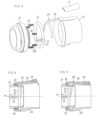
- the handheld power wrench illustrated in Fig. 1 comprises a cylindrical housing 10 formed with a tubular handle 11 and supporting a non-illustrated electric motor. At its rear end the housing 10 provided with a connection socket 13 for connection of a power and signal transferring cable communicating with a separate programmable operation control unit 14.
- the properties and operation order of the control unit is of a well known type and does form any part of the present invention. Therefore, it is not illustrated in further detail.
- the housing 10 At its forward end the housing 10 carries an angle head 16 with a square ended output shaft 18 adapted to carry a nut socket.
- the output shaft 18 extends in a lateral direction perpendicularly to the cylindrical housing 10 and is connected to the motor via an angle drive.
- the angle head 16 is connected to the housing 10 via a swivel coupling 20 for enabling setting of the angle head 16 in a number of alternative angular positions relative to the housing 10 such that the output shaft 18 may be directed in alternative angular dispositions relative to the housing 10.
- a trigger 24 is provided on the housing 10 for manual control of the power supply to the motor.
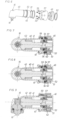
- the trigger 24 is carried by an annular sleeve element 26 which is freely rotatable relative to the housing 10.
- the trigger 24 is mounted on an arm 28 of a fork 29 which is pivotally supported on the sleeve element 26.
- the fork 29 is arranged to cooperate with an activation ring 31 coaxial with the housing 10 and formed with an axially protruding finger 32.
- the activation ring 31 is supported on and axially displaceable relative to a support sleeve 33 secured in the housing 10, and springs 30 are provided to bias the activation ring 31 towards a rear inactivated position.
- the support sleeve 33 carries a Hall element 34 acting as an activation means for accomplishing shifting of a non-illustrated power switching device, wherein activation of the Hall element 34 is accomplished by a magnet 35 carried on the finger 32 of the activation ring 31.
- Fig. 4 the trigger 24 as well as the activation ring 31 are illustrated in their rest positions retracted by the springs 30. In this position of the activation ring 31 the magnet 35 is out of cooperation with the Hall element 34 and no signal is emitted to activate the power switch.
- Fig. 5 the trigger 24 has been pressed down to an activated position thereby making the fork 29 displace the activation ring 31 forwards to a position where the Hall element 34 is activated by the magnet 35. This results in a signal being emitted by the Hall element 34 to activate the power switching device and start the wrench for operation.
- the activation ring 31 is not rotatable relative to the housing 10 but has a fixed annular position with the finger 32 in constant position for cooperation with the Hall element 34.
- the annular sleeve element 26 on which the trigger 24 is supported is freely rotatable relative to the housing 10, but due to the arrangement with the trigger 24 mounted on the fork 29 the activation ring 31 may be displaced into its active position independently of the actual angular position of the trigger 24.
- the angle head 16 carried at the forward end of the housing 10 comprises a casing 40 wherein a drive pinion 41 and the output shaft 18 are journalled.
- the drive pinion 41 is supported in a forward bearing 42 and a rear bearing 43, whereof the rear bearing 43 is a ball bearing with an outer race 45 is supported in a tubular neck portion 46 of the angle head casing 40.
- FIG. 2 there is illustrated a battery powered handheld power wrench wherein the rather bulky battery package 50, although it makes the wrench freely movable without cable connection, still causes occasional problems at getting access to difficult to reach screw joint locations.
- this type of wrenches there is a particular need for having the angle head 16 adjustable to get a favourable direction of the output shaft 18. In a less favourable direction of the output shaft 18 there is a risk that the battery package will get into contact with the structure adjacent the screw joint to be tightened and obstruct a proper wrench position.
- the angle head 16 rotatable and possible to be set in alternative angular positions relative to the housing 10.
- the neck portion 46 of the angle head casing 40 is freely rotatable relative to a mounting sleeve 51 which is rigidly connected to the wrench housing 10 via an inner thread 52.
- the neck portion 46 is provided with a row of indentations 53 distributed around its periphery, and a couple of balls 54 are provided to engage those indentations 53.
- This ball/indentation arrangement forms a locking device 55 by which the angle head 16 is lockable in alternative angular positions relative to the housing 10.
- the balls 54 are radially movable within apertures 56 in the mounting sleeve 51, and a surrounding manoeuver sleeve 57 is axially displaceable between a rear lock position in which the balls 54 are blocked from leaving the indentations 53 and a release position wherein the balls 54 are free to move out of the indentations 53 and unlock the angle head 16 for rotation relative to the mounting sleeve 51 and the housing 10.
- a number of springs 59 are provided to exert a bias force on the manoeuver sleeve 57 towards the lock position.
- the axial movability of the manoeuver sleeve 57 is limited by two lock rings 61, 62 mounted on the neck portion 46 of the angle head casing 40.
- the manoeuver sleeve 51 When it becomes necessary to change the angular position of the angle head 16 relative to the housing 10 to thereby facilitate accessibility to difficult to reach screw joint locations the manoeuver sleeve 51 is pulled forwardly against the bias force of the springs 59 wherein the balls 54 are free to leave their locking engagement with the indentations 53. Now the angle head 16 is unlocked relative to the housing 10 and could be rotated to a desired angular position. When that is done the manoeuver sleeve 51 is allowed to return to its lock position by the force of the springs 59, wherein the balls 54 reengage the indentations 53 and lock the angle head 10 against rotation.
Landscapes
- Engineering & Computer Science (AREA)
- Mechanical Engineering (AREA)
- Details Of Spanners, Wrenches, And Screw Drivers And Accessories (AREA)
- Portable Power Tools In General (AREA)
- Mechanisms For Operating Contacts (AREA)
Claims (7)
- Handgeführter Kraftschrauber, umfassend ein zylindrisches Gehäuse (10), einen Elektromotor, eine Ausgangswelle (18), die mit dem Motor verbunden ist, eine Leistungsschaltvorrichtung, die durch einen Auslöser (24) aktiviert wird, der sich an dem Gehäuse (10) befindet, und umfassend einen Winkelkopf (16), der an dem Gehäuse (10) gestützt ist und die Ausgangswelle (18) in einer sich lateral erstreckenden Position stützt,
dadurch gekennzeichnet, dass der Auslöser (24) auf einem ringförmigen Hülsenelement (26) gestützt ist und das Hülsenelement (26) in einer koaxialen Anordnung gestützt und relativ zu dem Gehäuse (10) drehbar ist, zum Freigeben einer Einstellung der Winkelposition des Auslösers (24) relativ zu dem Gehäuse (10). - Handgeführter Kraftschrauber nach Anspruch 1, wobei der Auslöser (24) eingerichtet ist, um die Schaltvorrichtung über einen axial verschiebbaren Aktivierungsring (31) zu aktivieren.
- Handgeführter Kraftschrauber nach Anspruch 2, wobei die Kraftschaltvorrichtung ein Hall-Element (34) einschließt, das eingerichtet ist, um durch einen Magneten (35) aktiviert zu werden, der durch den Aktivierungsring (31) gestützt wird.
- Handgeführter Kraftschrauber nach einem der Ansprüche 2 bis 3, wobei der Auslöser (24) eingerichtet ist, um die Verschiebung des Aktivierungsrings (31) über eine Gabel (29) zu bewirken.
- Handgeführter Kraftschrauber nach einem der Ansprüche 1 bis 4, wobei der Winkelkopf (16) an dem Gehäuse (10) befestigt ist und wobei der Winkelkopf (16) über eine Schwenkkopplung (20) mit dem Gehäuse (10) verbunden ist, um eine Drehung des Winkelkopfes (16) und eine Einstellung der Winkelposition der Ausgangswelle (18) relativ zu dem Gehäuse (10) freizugeben.
- Handgeführter Kraftschrauber nach Anspruch 5, wobei zwischen dem Winkelkopf (16) und dem Gehäuse (10) eine Verriegelungsvorrichtung (55) zum Arretieren des Winkelkopfes (16) in alternativen Winkelpositionen relativ zu dem Gehäuse (10) eingerichtet ist.
- Handgeführter Kraftschrauber nach Anspruch 6, wobei die Verriegelungsvorrichtung (55) eine Betätigungshülse (51), die zwischen einer Verriegelungsposition und einer Löseposition manuell umstellbar ist, und eine oder mehrere Federn (59) umfasst, die eingerichtet sind, um die Betätigungshülse (51) in Richtung der Verriegelungsposition vorzuspannen.
Applications Claiming Priority (2)
| Application Number | Priority Date | Filing Date | Title |
|---|---|---|---|
| SE1730158 | 2017-06-12 | ||
| PCT/EP2018/064403 WO2018228824A1 (en) | 2017-06-12 | 2018-06-01 | Power wrench with adjustable trigger position |
Publications (3)
| Publication Number | Publication Date |
|---|---|
| EP3638458A1 EP3638458A1 (de) | 2020-04-22 |
| EP3638458B1 true EP3638458B1 (de) | 2024-08-07 |
| EP3638458C0 EP3638458C0 (de) | 2024-08-07 |
Family
ID=62495803
Family Applications (1)
| Application Number | Title | Priority Date | Filing Date |
|---|---|---|---|
| EP18728876.6A Active EP3638458B1 (de) | 2017-06-12 | 2018-06-01 | Schlagschrauber mit einstellbarer trigger position |
Country Status (6)
| Country | Link |
|---|---|
| US (1) | US11607794B2 (de) |
| EP (1) | EP3638458B1 (de) |
| JP (1) | JP7222926B2 (de) |
| KR (1) | KR102528696B1 (de) |
| CN (1) | CN110769983B (de) |
| WO (1) | WO2018228824A1 (de) |
Families Citing this family (3)
| Publication number | Priority date | Publication date | Assignee | Title |
|---|---|---|---|---|
| DE112018003406T5 (de) | 2017-08-03 | 2020-03-19 | Makita Corporation | Ratschenschlüssel |
| TWD198698S (zh) * | 2018-09-12 | 2019-07-21 | 優鋼機械股份有限公司 | 扭力扳手 |
| US12576487B2 (en) | 2022-03-08 | 2026-03-17 | Black & Decker Inc. | Power tool |
Family Cites Families (18)
| Publication number | Priority date | Publication date | Assignee | Title |
|---|---|---|---|---|
| US3328184A (en) | 1963-07-02 | 1967-06-27 | Kimberly Clark Co | Printing paper having opaque cellular coating and method and composition for forming the same |
| DE1478828A1 (de) * | 1964-10-24 | 1969-03-06 | Bosch Gmbh Robert | Motorisch angetriebenes Schraubgeraet |
| SE503326C2 (sv) | 1994-07-08 | 1996-05-28 | Atlas Copco Tools Ab | Vinkelmutterdragare |
| JP4721535B2 (ja) * | 2001-02-28 | 2011-07-13 | 勝行 戸津 | 電動回転工具 |
| US6928902B1 (en) * | 2003-03-20 | 2005-08-16 | Luis P. Eyssallenne | Air powered wrench device with pivotable head and method of using |
| US20070084310A1 (en) * | 2005-10-14 | 2007-04-19 | Sp Air Kabushiki Kaisha | Air ratchet tool with rotatable head |
| SE529928C2 (sv) | 2006-05-09 | 2008-01-08 | Atlas Copco Tools Ab | Låsanordning för portabelt verktyg |
| SE531646C2 (sv) | 2007-10-17 | 2009-06-16 | Atlas Copco Tools Ab | Skruvdragare med organ för övervakning av en reaktionsarm |
| SE532720C2 (sv) | 2008-12-22 | 2010-03-23 | Atlas Copco Tools Ab | Handhållen mutterdragare med manuellt styrt effektstyrorgan |
| JP4961418B2 (ja) | 2008-12-26 | 2012-06-27 | オムロン株式会社 | 電動工具 |
| JP5546829B2 (ja) * | 2009-10-27 | 2014-07-09 | 株式会社マキタ | 電動工具 |
| DE102011084432A1 (de) * | 2011-10-13 | 2013-04-18 | Robert Bosch Gmbh | Handwerkzeugmaschine mit mechanisch gesteuerter automatischer Ein- und Ausschaltfunktion |
| US9186788B2 (en) * | 2012-11-15 | 2015-11-17 | Techtronic Power Tools Technology Limited | Lockout mechanism |
| DE102013213806A1 (de) | 2012-11-15 | 2014-05-15 | Robert Bosch Gmbh | Werkzeugvorsatz für eine Handwerkzeugmaschine |
| DE102013218190A1 (de) | 2013-09-11 | 2015-03-12 | Wagner Vermögensverwaltungs-GmbH & Co. KG | Drehschrauber sowie Verfahren zum Durchführen eines Schraubvorgangs mit einem Drehschrauber |
| DE102014214982A1 (de) * | 2014-07-30 | 2016-02-04 | Robert Bosch Gmbh | Elektrowerkzeugmaschine |
| US20160288304A1 (en) | 2015-04-02 | 2016-10-06 | Hsuan-Sen Shiao | Electronic Torque Wrench |
| TWI548497B (zh) * | 2015-08-25 | 2016-09-11 | Pneumatic tools with trigger |
-
2018
- 2018-06-01 WO PCT/EP2018/064403 patent/WO2018228824A1/en not_active Ceased
- 2018-06-01 EP EP18728876.6A patent/EP3638458B1/de active Active
- 2018-06-01 CN CN201880038407.XA patent/CN110769983B/zh active Active
- 2018-06-01 US US16/621,658 patent/US11607794B2/en active Active
- 2018-06-01 JP JP2019568321A patent/JP7222926B2/ja active Active
- 2018-06-01 KR KR1020197038724A patent/KR102528696B1/ko active Active
Also Published As
| Publication number | Publication date |
|---|---|
| JP2020523207A (ja) | 2020-08-06 |
| US11607794B2 (en) | 2023-03-21 |
| WO2018228824A1 (en) | 2018-12-20 |
| JP7222926B2 (ja) | 2023-02-15 |
| CN110769983B (zh) | 2023-03-14 |
| CN110769983A (zh) | 2020-02-07 |
| KR102528696B1 (ko) | 2023-05-08 |
| EP3638458A1 (de) | 2020-04-22 |
| KR20200016898A (ko) | 2020-02-17 |
| US20210187723A1 (en) | 2021-06-24 |
| BR112019025054A2 (pt) | 2020-06-16 |
| EP3638458C0 (de) | 2024-08-07 |
Similar Documents
| Publication | Publication Date | Title |
|---|---|---|
| US11273540B2 (en) | Power wrench with angle drive | |
| EP3638458B1 (de) | Schlagschrauber mit einstellbarer trigger position | |
| EP2200783B1 (de) | Kraftschrauber mit drehmomentstützensteuerung | |
| USRE35617E (en) | Torque limiting device for air impact tool | |
| JP5059230B2 (ja) | タング無し螺旋状コイルインサート挿入工具 | |
| KR102028010B1 (ko) | 간접 활선 작업용 회전 기능 그립 올 클램프 스틱 및 이를 이용한 간접활선용 공구 회전 조작 방법 | |
| US7044036B1 (en) | Preset torque wrench with multiple setting torque selector mechanism | |
| SE1050788A1 (sv) | Låsmutter för en reaktionsarm | |
| US3867855A (en) | Lever actuated ratchet wrench | |
| EP1996373B1 (de) | Elektrisch angetriebenes werkzeug mit schwenkbarer kabelverbindung | |
| JPH05212687A (ja) | アングルヘッド用係止装置 | |
| WO2016198115A1 (en) | Nut socket unit for power wrenches | |
| US3650165A (en) | Ratchet tool | |
| EP2990163B1 (de) | Elektrowerkzeug | |
| US12384001B2 (en) | Electric tool | |
| JP2013132704A (ja) | トルクレンチ装置及びこれを用いたトルクレンチ付きナットランナー | |
| BR112019025054B1 (pt) | Chave de força com posição de gatilho ajustável | |
| EP3441189B1 (de) | Drehmomenteinstellvorrichtung | |
| CN107322057B (zh) | 一种手紧钻夹头 | |
| US20190329328A1 (en) | Power tool with working implement attachment | |
| US20190047126A1 (en) | Torque-adjusting apparatus | |
| SE532753C2 (sv) | Portabelt kraftverktyg med ett handtag uppvisande en effektstyrningstangent |
Legal Events
| Date | Code | Title | Description |
|---|---|---|---|
| STAA | Information on the status of an ep patent application or granted ep patent |
Free format text: STATUS: UNKNOWN |
|
| STAA | Information on the status of an ep patent application or granted ep patent |
Free format text: STATUS: THE INTERNATIONAL PUBLICATION HAS BEEN MADE |
|
| PUAI | Public reference made under article 153(3) epc to a published international application that has entered the european phase |
Free format text: ORIGINAL CODE: 0009012 |
|
| STAA | Information on the status of an ep patent application or granted ep patent |
Free format text: STATUS: REQUEST FOR EXAMINATION WAS MADE |
|
| 17P | Request for examination filed |
Effective date: 20191122 |
|
| AK | Designated contracting states |
Kind code of ref document: A1 Designated state(s): AL AT BE BG CH CY CZ DE DK EE ES FI FR GB GR HR HU IE IS IT LI LT LU LV MC MK MT NL NO PL PT RO RS SE SI SK SM TR |
|
| AX | Request for extension of the european patent |
Extension state: BA ME |
|
| DAV | Request for validation of the european patent (deleted) | ||
| DAX | Request for extension of the european patent (deleted) | ||
| STAA | Information on the status of an ep patent application or granted ep patent |
Free format text: STATUS: EXAMINATION IS IN PROGRESS |
|
| 17Q | First examination report despatched |
Effective date: 20210429 |
|
| GRAP | Despatch of communication of intention to grant a patent |
Free format text: ORIGINAL CODE: EPIDOSNIGR1 |
|
| STAA | Information on the status of an ep patent application or granted ep patent |
Free format text: STATUS: GRANT OF PATENT IS INTENDED |
|
| INTG | Intention to grant announced |
Effective date: 20240411 |
|
| RIN1 | Information on inventor provided before grant (corrected) |
Inventor name: ANDERSSON, PATRIK LEANDER |
|
| GRAS | Grant fee paid |
Free format text: ORIGINAL CODE: EPIDOSNIGR3 |
|
| GRAA | (expected) grant |
Free format text: ORIGINAL CODE: 0009210 |
|
| STAA | Information on the status of an ep patent application or granted ep patent |
Free format text: STATUS: THE PATENT HAS BEEN GRANTED |
|
| AK | Designated contracting states |
Kind code of ref document: B1 Designated state(s): AL AT BE BG CH CY CZ DE DK EE ES FI FR GB GR HR HU IE IS IT LI LT LU LV MC MK MT NL NO PL PT RO RS SE SI SK SM TR |
|
| REG | Reference to a national code |
Ref country code: GB Ref legal event code: FG4D |
|
| REG | Reference to a national code |
Ref country code: CH Ref legal event code: EP |
|
| REG | Reference to a national code |
Ref country code: IE Ref legal event code: FG4D |
|
| REG | Reference to a national code |
Ref country code: DE Ref legal event code: R096 Ref document number: 602018072729 Country of ref document: DE |
|
| U01 | Request for unitary effect filed |
Effective date: 20240902 |
|
| U07 | Unitary effect registered |
Designated state(s): AT BE BG DE DK EE FI FR IT LT LU LV MT NL PT RO SE SI Effective date: 20240912 |
|
| PG25 | Lapsed in a contracting state [announced via postgrant information from national office to epo] |
Ref country code: NO Free format text: LAPSE BECAUSE OF FAILURE TO SUBMIT A TRANSLATION OF THE DESCRIPTION OR TO PAY THE FEE WITHIN THE PRESCRIBED TIME-LIMIT Effective date: 20241107 |
|
| PG25 | Lapsed in a contracting state [announced via postgrant information from national office to epo] |
Ref country code: PL Free format text: LAPSE BECAUSE OF FAILURE TO SUBMIT A TRANSLATION OF THE DESCRIPTION OR TO PAY THE FEE WITHIN THE PRESCRIBED TIME-LIMIT Effective date: 20240807 Ref country code: GR Free format text: LAPSE BECAUSE OF FAILURE TO SUBMIT A TRANSLATION OF THE DESCRIPTION OR TO PAY THE FEE WITHIN THE PRESCRIBED TIME-LIMIT Effective date: 20241108 |
|
| PG25 | Lapsed in a contracting state [announced via postgrant information from national office to epo] |
Ref country code: IS Free format text: LAPSE BECAUSE OF FAILURE TO SUBMIT A TRANSLATION OF THE DESCRIPTION OR TO PAY THE FEE WITHIN THE PRESCRIBED TIME-LIMIT Effective date: 20241207 |
|
| PG25 | Lapsed in a contracting state [announced via postgrant information from national office to epo] |
Ref country code: HR Free format text: LAPSE BECAUSE OF FAILURE TO SUBMIT A TRANSLATION OF THE DESCRIPTION OR TO PAY THE FEE WITHIN THE PRESCRIBED TIME-LIMIT Effective date: 20240807 |
|
| PG25 | Lapsed in a contracting state [announced via postgrant information from national office to epo] |
Ref country code: ES Free format text: LAPSE BECAUSE OF FAILURE TO SUBMIT A TRANSLATION OF THE DESCRIPTION OR TO PAY THE FEE WITHIN THE PRESCRIBED TIME-LIMIT Effective date: 20240807 Ref country code: RS Free format text: LAPSE BECAUSE OF FAILURE TO SUBMIT A TRANSLATION OF THE DESCRIPTION OR TO PAY THE FEE WITHIN THE PRESCRIBED TIME-LIMIT Effective date: 20241107 |
|
| PG25 | Lapsed in a contracting state [announced via postgrant information from national office to epo] |
Ref country code: RS Free format text: LAPSE BECAUSE OF FAILURE TO SUBMIT A TRANSLATION OF THE DESCRIPTION OR TO PAY THE FEE WITHIN THE PRESCRIBED TIME-LIMIT Effective date: 20241107 Ref country code: PL Free format text: LAPSE BECAUSE OF FAILURE TO SUBMIT A TRANSLATION OF THE DESCRIPTION OR TO PAY THE FEE WITHIN THE PRESCRIBED TIME-LIMIT Effective date: 20240807 Ref country code: NO Free format text: LAPSE BECAUSE OF FAILURE TO SUBMIT A TRANSLATION OF THE DESCRIPTION OR TO PAY THE FEE WITHIN THE PRESCRIBED TIME-LIMIT Effective date: 20241107 Ref country code: IS Free format text: LAPSE BECAUSE OF FAILURE TO SUBMIT A TRANSLATION OF THE DESCRIPTION OR TO PAY THE FEE WITHIN THE PRESCRIBED TIME-LIMIT Effective date: 20241207 Ref country code: HR Free format text: LAPSE BECAUSE OF FAILURE TO SUBMIT A TRANSLATION OF THE DESCRIPTION OR TO PAY THE FEE WITHIN THE PRESCRIBED TIME-LIMIT Effective date: 20240807 Ref country code: GR Free format text: LAPSE BECAUSE OF FAILURE TO SUBMIT A TRANSLATION OF THE DESCRIPTION OR TO PAY THE FEE WITHIN THE PRESCRIBED TIME-LIMIT Effective date: 20241108 Ref country code: ES Free format text: LAPSE BECAUSE OF FAILURE TO SUBMIT A TRANSLATION OF THE DESCRIPTION OR TO PAY THE FEE WITHIN THE PRESCRIBED TIME-LIMIT Effective date: 20240807 |
|
| PG25 | Lapsed in a contracting state [announced via postgrant information from national office to epo] |
Ref country code: SM Free format text: LAPSE BECAUSE OF FAILURE TO SUBMIT A TRANSLATION OF THE DESCRIPTION OR TO PAY THE FEE WITHIN THE PRESCRIBED TIME-LIMIT Effective date: 20240807 |
|
| PG25 | Lapsed in a contracting state [announced via postgrant information from national office to epo] |
Ref country code: CZ Free format text: LAPSE BECAUSE OF FAILURE TO SUBMIT A TRANSLATION OF THE DESCRIPTION OR TO PAY THE FEE WITHIN THE PRESCRIBED TIME-LIMIT Effective date: 20240807 |
|
| PG25 | Lapsed in a contracting state [announced via postgrant information from national office to epo] |
Ref country code: SK Free format text: LAPSE BECAUSE OF FAILURE TO SUBMIT A TRANSLATION OF THE DESCRIPTION OR TO PAY THE FEE WITHIN THE PRESCRIBED TIME-LIMIT Effective date: 20240807 |
|
| PLBE | No opposition filed within time limit |
Free format text: ORIGINAL CODE: 0009261 |
|
| STAA | Information on the status of an ep patent application or granted ep patent |
Free format text: STATUS: NO OPPOSITION FILED WITHIN TIME LIMIT |
|
| 26N | No opposition filed |
Effective date: 20250508 |
|
| U20 | Renewal fee for the european patent with unitary effect paid |
Year of fee payment: 8 Effective date: 20250628 |
|
| REG | Reference to a national code |
Ref country code: CH Ref legal event code: H13 Free format text: ST27 STATUS EVENT CODE: U-0-0-H10-H13 (AS PROVIDED BY THE NATIONAL OFFICE) Effective date: 20260127 |
|
| PG25 | Lapsed in a contracting state [announced via postgrant information from national office to epo] |
Ref country code: MC Free format text: LAPSE BECAUSE OF FAILURE TO SUBMIT A TRANSLATION OF THE DESCRIPTION OR TO PAY THE FEE WITHIN THE PRESCRIBED TIME-LIMIT Effective date: 20240807 |
|
| GBPC | Gb: european patent ceased through non-payment of renewal fee |
Effective date: 20250601 |
|
| PG25 | Lapsed in a contracting state [announced via postgrant information from national office to epo] |
Ref country code: GB Free format text: LAPSE BECAUSE OF NON-PAYMENT OF DUE FEES Effective date: 20250601 |
|
| PG25 | Lapsed in a contracting state [announced via postgrant information from national office to epo] |
Ref country code: IE Free format text: LAPSE BECAUSE OF NON-PAYMENT OF DUE FEES Effective date: 20250601 |