EP2200783B1 - Kraftschrauber mit drehmomentstützensteuerung - Google Patents
Kraftschrauber mit drehmomentstützensteuerung Download PDFInfo
- Publication number
- EP2200783B1 EP2200783B1 EP08839303.8A EP08839303A EP2200783B1 EP 2200783 B1 EP2200783 B1 EP 2200783B1 EP 08839303 A EP08839303 A EP 08839303A EP 2200783 B1 EP2200783 B1 EP 2200783B1
- Authority
- EP
- European Patent Office
- Prior art keywords
- housing
- activation unit
- power wrench
- power
- motor
- Prior art date
- Legal status (The legal status is an assumption and is not a legal conclusion. Google has not performed a legal analysis and makes no representation as to the accuracy of the status listed.)
- Not-in-force
Links
Images

Classifications
-
- B—PERFORMING OPERATIONS; TRANSPORTING
- B25—HAND TOOLS; PORTABLE POWER-DRIVEN TOOLS; MANIPULATORS
- B25B—TOOLS OR BENCH DEVICES NOT OTHERWISE PROVIDED FOR, FOR FASTENING, CONNECTING, DISENGAGING OR HOLDING
- B25B21/00—Portable power-driven screw or nut setting or loosening tools; Attachments for drilling apparatus serving the same purpose
- B25B21/008—Portable power-driven screw or nut setting or loosening tools; Attachments for drilling apparatus serving the same purpose with automatic change-over from high speed-low torque mode to low speed-high torque mode
-
- B—PERFORMING OPERATIONS; TRANSPORTING
- B25—HAND TOOLS; PORTABLE POWER-DRIVEN TOOLS; MANIPULATORS
- B25B—TOOLS OR BENCH DEVICES NOT OTHERWISE PROVIDED FOR, FOR FASTENING, CONNECTING, DISENGAGING OR HOLDING
- B25B23/00—Details of, or accessories for, spanners, wrenches, screwdrivers
- B25B23/0007—Connections or joints between tool parts
- B25B23/0014—Screwdriver- or wrench-heads provided with cardan joints or the like
-
- B—PERFORMING OPERATIONS; TRANSPORTING
- B25—HAND TOOLS; PORTABLE POWER-DRIVEN TOOLS; MANIPULATORS
- B25B—TOOLS OR BENCH DEVICES NOT OTHERWISE PROVIDED FOR, FOR FASTENING, CONNECTING, DISENGAGING OR HOLDING
- B25B23/00—Details of, or accessories for, spanners, wrenches, screwdrivers
- B25B23/0078—Reaction arms
-
- B—PERFORMING OPERATIONS; TRANSPORTING
- B25—HAND TOOLS; PORTABLE POWER-DRIVEN TOOLS; MANIPULATORS
- B25F—COMBINATION OR MULTI-PURPOSE TOOLS NOT OTHERWISE PROVIDED FOR; DETAILS OR COMPONENTS OF PORTABLE POWER-DRIVEN TOOLS NOT PARTICULARLY RELATED TO THE OPERATIONS PERFORMED AND NOT OTHERWISE PROVIDED FOR
- B25F5/00—Details or components of portable power-driven tools not particularly related to the operations performed and not otherwise provided for
- B25F5/02—Construction of casings, bodies or handles
- B25F5/025—Construction of casings, bodies or handles with torque reaction bars for rotary tools
- B25F5/026—Construction of casings, bodies or handles with torque reaction bars for rotary tools in the form of an auxiliary handle
-
- B—PERFORMING OPERATIONS; TRANSPORTING
- B25—HAND TOOLS; PORTABLE POWER-DRIVEN TOOLS; MANIPULATORS
- B25F—COMBINATION OR MULTI-PURPOSE TOOLS NOT OTHERWISE PROVIDED FOR; DETAILS OR COMPONENTS OF PORTABLE POWER-DRIVEN TOOLS NOT PARTICULARLY RELATED TO THE OPERATIONS PERFORMED AND NOT OTHERWISE PROVIDED FOR
- B25F5/00—Details or components of portable power-driven tools not particularly related to the operations performed and not otherwise provided for
- B25F5/02—Construction of casings, bodies or handles
- B25F5/025—Construction of casings, bodies or handles with torque reaction bars for rotary tools
- B25F5/028—Construction of casings, bodies or handles with torque reaction bars for rotary tools to be supported by a fixed object
Definitions
- the invention relates to a portable power wrench with a housing consisting of two parts which are swivelled relative to each other, wherein a first part comprises a handle and a rotation motor, and a second part comprises a reduction gearing and a laterally extending reaction bar for transferring a reaction torque from the second housing part to a stationary reaction torque supporting object.
- the housing is divided into a rear part with the drive motor and a handle for the operator, and a forward part with a reduction gearing and a laterally extending reaction bar for transferring reaction torque from the forward housing part to a stationary object forming a reaction torque support.
- the swivel connection between the housing parts and the reaction bar prevents the operator from being exposed to heavy reaction torque loads transferred to the forward housing part via the reduction gearing and enables at the same time the handle to be freely positioned for a comfortable handling of the power wrench notwithstanding the direction of the reaction bar.
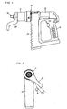
- the power wrench illustrated in the drawing figures comprises a housing 10 divided into two parts, namely a forward part 11 and a rear part 12.
- the rear part 12 includes a transverse section 13 enclosing a rotation motor and a mechanical power transmission (not illustrated), a handle 14 for manual support of the wrench and an electronic control unit for controlling the power supply to the motor.
- a swivel connection 16 including a ball bearing 17. This means that the forward part 11 is rotatable relative to the rear part 12.
- the forward housing part 11 comprises a reduction gearing in two or more stages for multiplying the torque delivered by the motor to an output shaft 18.
- the latter is adapted to carry a nut socket.
- the forward housing part 11 also carries a rigidly attached reaction bar 20 which extends laterally from the housing and is intended to take support against a suitable stationary object A for transferring the reaction torque induced in the forward part 11 of the housing 10 during torque deliverance via the output shaft 18. See Fig. 2 .
- the swivel connection 16 between the two housing parts 11 and 12 in combination with the reaction bar 20 aims to prevent reaction torque from reaching the rear part 12 of the housing 10 and the operator via the handle 14.
- the swivel connection 16 between the two housing parts 11,12 also means that the handle 14 could be maintained in a position suitable for comfortable handling of the power wrench, notwithstanding the angular position of the reaction bar 20.
- the rear housing part 12 includes a rigidly attached bearing ring 21 with an external ball race 22 for supporting a number of bearing balls 23.
- the forward housing part 11 comprises a corresponding internal ball race 24 and forms together with the balls 23 and the ball race 22 the ball bearing 17.
- a rotation sensing means in the form of an activation unit 25-27 and a sensor 30.
- the activation unit 25-27 comprises an activation element 25 with a magnet 26 movably supported on the bearing ring 21, and a ball 27.
- the activation element 25 and the ball 27 are biased by a spring 28 to make the ball 27 engage either one of a peripheral row of indentations 29 in the forward housing part 11.
- the activation unit 25-27 is caused to move radially as the forward housing part 11 is rotated relative to the rear housing part 12 in that the ball 27 is forced to "jump" from one indentation 29 to the next.
- the indentations 29 act as a cam means to accomplish these radial movements of the activation unit 25-27.
- the magnet 26 of the activation element 25 co-operates with a Hall-type sensor 30 located on a printed circuit board 31, whereby the sensor 30 is arranged to accomplish electric signals at radial movement of the activation element 25 corresponding to a relative rotation between the two housing parts 11,12.
- the rear housing part 12 is also provided with two more spring biased position retaining balls 34,35 arranged to co-operate with the row of indentations 29 equally distributed along the periphery of the forward housing part 11.
- the purpose of these two balls 34,35 is to restrain free rotation of the housing parts 11,12 relative to each other and to retain the housing parts in desired relative positions at handling of the wrench.
- the non-illustrated electronic control unit in the rear housing part 12 communicates with the sensor 30 and is programmed to shut off or at least substantially reduce the motor power in case the sensor 30 indicates more than a predetermined relative rotation between the housing parts 11,12 after the motor has started rotating.
- the relative rotation limit could be fifteen, thirty, forty-five etc. degrees, i.e. a multiple of fifteen degrees, because the number of indentations in the forward housing part 11 is twenty-four. This means that the number of alternative relative positions of the housing parts 11,12 is also twenty-four, and that the angular distance between these positions is fifteen degrees. This is the shortest angular displacement ⁇ of the reaction bar 20 before a motor power reduction can be obtained in case the reaction bar 20 is out of contact with a stationary support object.
- the angle ⁇ to be covered by the reaction bar 20 before it gets into contact with a stationary support object is fifteen degrees before the activation unit 25-27 initiates a motor power reduction or shut-off. In most cases this is acceptable and not considered hazardous to the operator. In some applications thirty or even forty-five degrees are acceptable.
- the described device provides a safety means for the operator to prevent injuries when starting a tightening operation of a screw joint, because the reaction bar may not be accurately positioned as the motor is started and a sudden rotation movement of the reaction bar might be the result.
- Fig. 2 there is illustrated that the reaction bar 20 has to be moved an angle ⁇ before it takes support against the stationary support object A.
- the illustrated angle ⁇ is quite small and the control unit could be set not to reduce the motor power at such a small angle at the start of tightening operation.
- the invention also aims to prevent damages and injuries to the operator should the power wrench unintentionally be set to rotate in the loosening direction of the screw joint. That would result in a total lack of stationary support for the reaction bar 20 and a substantial swinging movement of the reaction bar 20. This could be very hazardous to the operator and is effectively prevented by the device according to the invention.
- reaction bar may have different designs since it has to be individually designed to adapt to the actual application.
- rotation sensing means including the indentations and the radially movable activation unit but may as well comprise other types of movement detecting devices, for instance a magnetised ring fitted to one of the housing parts and a sensor carried by the other housing part.
- a magnetised ring fitted to one of the housing parts and a sensor carried by the other housing part.
- Such a ring could be magnetised in a great number of transverse bands such that very small rotation increments could be indicated. That would increase the possibility to more freely choose the acceptable rotation angle of the reaction bar 20 at the start of the power wrench motor.
- some sort of braking device to prevent free relative rotation between the housing parts at handling of the power wrench before and after each screw tightening operation.
Landscapes
- Engineering & Computer Science (AREA)
- Mechanical Engineering (AREA)
- Details Of Spanners, Wrenches, And Screw Drivers And Accessories (AREA)
Claims (5)
- Kraftschrauber, umfassend ein Gehäuse mit einem ersten Teil (12), der einen Drehmotor und einen Griff (14) zum Halten des Schraubers mit der Hand enthält, einem zweiten Teil (11), der ein Untersetzungsgetriebe enthält, und einer Ausgangswelle (18), eine Schwenkverbindung (16) zwischen dem ersten Teil (12) und dem zweiten Teil (11), und eine sich seitlich erstreckende Drehmomentstütze (20), die starr an dem zweiten Teil (11) befestigt ist und dafür vorgesehen ist, sich an einem unbeweglichen Gegenstand (A) abzustützen,
dadurch gekennzeichnet, dass ein Winkelmessmittel (25 bis 30) an der Schwenkverbindung (16) vorgesehen und so angeordnet ist, dass es als Reaktion auf Winkelbewegungen zwischen dem ersten Teil (12) und dem zweiten Teil (11) Signale abgibt, und dass eine Leistungssteuerungseinheit mit dem Motor und dem Winkelmessmittel (25 bis 30) verbunden ist, wobei die Leistungssteuerungseinheit so angeordnet ist, dass sie zumindest im Wesentlichen die Stromzufuhr zum Motor herabsetzt, wenn eine voreingestellte maximale Winkelbewegung (α) zwischen dem ersten und zweiten Gehäuseteil (12, 11) überschritten wird, wenn der Motor gestartet wird. - Kraftschrauber nach Anspruch 1, wobei das Winkelmessmittel (25 bis 30) eine Aktivierungseinheit (25, 26), ein Kurvenmittel (27, 29), das sich zwischen den Teilen (11, 12) befindet und so angeordnet ist, dass es die Aktivierungseinheit (25, 26) bei der relativen Drehung der Teile (11, 12) bewegt, und einen Sensor (30) umfasst, der von der Aktivierungseinheit (25, 26) aktiviert wird und als Reaktion auf die Bewegung der Aktivierungseinheit (25, 26) Signale erzeugt.
- Kraftschrauber nach Anspruch 1 oder 2, wobei die Aktivierungseinheit (25, 26) einen Magneten (26) umfasst, und der Sensor (30) einen Hall-Sensor umfasst, der von dem Magneten (26) bei der Bewegung der Aktivierungseinheit (25, 26) aktiviert wird.
- Kraftschrauber nach Anspruch 2 oder 3, wobei das Kurvenmittel (27, 29) eine am Rand befindliche Reihe von Vertiefungen (29) in einem der Gehäuseteile (11) und eine Kugel umfasst, die an dem anderen Gehäuseteil (12) gehalten ist, um in die Vertiefungen einzugreifen und einen Teil der Aktivierungseinheit (25, 26) bildet.
- Kraftschrauber nach Anspruch 4, wobei mindestens eine federbelastete Kugel (34, 35) an einem Gehäuseteil angeordnet ist, um mit der Reihe von Vertiefungen (29) an dem anderen Gehäuseteil zusammenzuwirken, um ein Drehbremsmittel zwischen den Gehäuseteilen (11, 12) zu bilden.
Applications Claiming Priority (2)
| Application Number | Priority Date | Filing Date | Title |
|---|---|---|---|
| SE0702315A SE531646C2 (sv) | 2007-10-17 | 2007-10-17 | Skruvdragare med organ för övervakning av en reaktionsarm |
| PCT/SE2008/000598 WO2009051543A1 (en) | 2007-10-17 | 2008-10-15 | Power wrench with reaction bar controlling means |
Publications (3)
| Publication Number | Publication Date |
|---|---|
| EP2200783A1 EP2200783A1 (de) | 2010-06-30 |
| EP2200783A4 EP2200783A4 (de) | 2013-03-20 |
| EP2200783B1 true EP2200783B1 (de) | 2014-06-25 |
Family
ID=40567629
Family Applications (1)
| Application Number | Title | Priority Date | Filing Date |
|---|---|---|---|
| EP08839303.8A Not-in-force EP2200783B1 (de) | 2007-10-17 | 2008-10-15 | Kraftschrauber mit drehmomentstützensteuerung |
Country Status (6)
| Country | Link |
|---|---|
| US (1) | US8261642B2 (de) |
| EP (1) | EP2200783B1 (de) |
| JP (1) | JP5325226B2 (de) |
| CN (1) | CN101861232B (de) |
| SE (1) | SE531646C2 (de) |
| WO (1) | WO2009051543A1 (de) |
Cited By (1)
| Publication number | Priority date | Publication date | Assignee | Title |
|---|---|---|---|---|
| EP4582219A1 (de) | 2024-01-08 | 2025-07-09 | M-PT Matjeschk-PowerTools GmbH & Co. KG | Schraubwerkzeug-drehmomentstütze, set mit einer schraubwerkzeug-drehmomentstütze, werkzeugbaugruppe und verfahren zum anpassen einer schraubwerkzeug-drehmomentstütze |
Families Citing this family (25)
| Publication number | Priority date | Publication date | Assignee | Title |
|---|---|---|---|---|
| SE533215C2 (sv) * | 2008-05-08 | 2010-07-20 | Atlas Copco Tools Ab | Metod och anordning för åtdragning av förband |
| DE102009001132B4 (de) | 2009-02-25 | 2022-04-28 | Robert Bosch Gmbh | Elektrowerkzeug |
| SE533830C2 (sv) * | 2009-06-11 | 2011-02-01 | Atlas Copco Tools Ab | Mutterdragare med växelhus och parametergivare |
| DE102009046789A1 (de) * | 2009-11-17 | 2011-05-19 | Robert Bosch Gmbh | Handwerkzeugmaschinenvorrichtung |
| US8418778B2 (en) | 2010-01-07 | 2013-04-16 | Black & Decker Inc. | Power screwdriver having rotary input control |
| EP2521832B1 (de) | 2010-01-07 | 2020-03-25 | Black & Decker, Inc. | Elektrischer schraubenzieher mit drehungseingabesteuerung |
| US9475180B2 (en) | 2010-01-07 | 2016-10-25 | Black & Decker Inc. | Power tool having rotary input control |
| US9266178B2 (en) | 2010-01-07 | 2016-02-23 | Black & Decker Inc. | Power tool having rotary input control |
| EP2631035B1 (de) | 2012-02-24 | 2019-10-16 | Black & Decker Inc. | Elektrisches Werkzeug |
| CN103522261B (zh) * | 2012-07-04 | 2016-03-16 | 青岛天力建筑加固工程有限公司 | 自供反扭矩电动工具 |
| US9108307B2 (en) | 2012-08-31 | 2015-08-18 | Honda Motor Co., Ltd. | Apparatus including powered tool configured to fasten fastener to assembly |
| FR2996483B1 (fr) * | 2012-10-05 | 2015-04-17 | Renault Georges Ets | Dispositif de vissage sans reaction dans la poignee |
| US9616557B2 (en) | 2013-03-14 | 2017-04-11 | Black & Decker Inc. | Nosepiece and magazine for power screwdriver |
| DE102015111570A1 (de) * | 2015-07-16 | 2017-01-19 | Jörg Hohmann | Drehschrauber |
| DE102017105025A1 (de) * | 2017-03-09 | 2018-09-13 | Frank Hohmann | Anordnung aus einem Reaktionsmomente ableitenden Stützarm und einem Drehschrauber |
| GB2563067B (en) * | 2017-06-02 | 2022-08-10 | Enerpac Uk Ltd | Torque wrench and reaction arm assembly with safety tether |
| WO2018228824A1 (en) | 2017-06-12 | 2018-12-20 | Atlas Copco Industrial Technique Ab | Power wrench with adjustable trigger position |
| US11273540B2 (en) | 2017-06-12 | 2022-03-15 | Atlas Copco Industrial Technique Ab | Power wrench with angle drive |
| US11897110B2 (en) | 2017-11-07 | 2024-02-13 | Milwaukee Electric Tool Corporation | Non-contact speed selector switch in rotary power tool |
| TWI659807B (zh) * | 2018-08-16 | 2019-05-21 | 佳銘精密工業有限公司 | 扭力接頭結構 |
| CN114096382B (zh) | 2019-05-13 | 2024-07-23 | 米沃奇电动工具公司 | 用于电动工具的具有旋转磁传感器的非接触式触发器 |
| CN114868513A (zh) | 2021-02-05 | 2022-08-09 | 米沃奇电动工具公司 | 用于割草机的非接触开关 |
| CN116460784A (zh) * | 2022-12-29 | 2023-07-21 | 陕西东方航空仪表有限责任公司 | 带角度功能的电动定扭扳手 |
| CN117648031B (zh) * | 2023-11-21 | 2025-07-15 | 张家港华捷电子有限公司 | 一种电钻防扭手参数自适应用户的方法及系统 |
| GB2643869A (en) * | 2024-08-28 | 2026-03-11 | Norbar Torque Tools | A torque tool and methods of operating a torque tool |
Family Cites Families (18)
| Publication number | Priority date | Publication date | Assignee | Title |
|---|---|---|---|---|
| US4155278A (en) * | 1977-09-06 | 1979-05-22 | Cooper Industries, Inc. | Swivel head reaction bar nut runner |
| JPS5820757B2 (ja) * | 1978-09-26 | 1983-04-25 | ザ ロ−タ− トウ−ル カンパニ− | スウイベルヘツド反動棒付きナツトランナ− |
| SE427811B (sv) * | 1981-11-23 | 1983-05-09 | Atlas Copco Ab | Skruvdragare med reaktionsmomentupptagande organ |
| US4462282A (en) | 1982-11-15 | 1984-07-31 | Dresser Industries, Inc. | Power tool with torque reaction bar |
| DE3422522A1 (de) * | 1984-06-16 | 1985-12-19 | Deutsche Gardner-Denver GmbH, 7084 Westhausen | Streckgrenzgesteuertes anziehverfahren fuer verschraubungen |
| JP2506758Y2 (ja) * | 1990-03-07 | 1996-08-14 | 株式会社明電舎 | 回転工具装置 |
| DE19646382A1 (de) * | 1996-11-11 | 1998-05-14 | Hilti Ag | Handgerät |
| DE19647813C2 (de) * | 1996-11-19 | 2003-07-03 | Joerg Hohmann | Kraftschrauber |
| DE19900882A1 (de) * | 1999-01-12 | 2000-07-13 | Bosch Gmbh Robert | Handwerkzeugmaschine |
| US6152243A (en) * | 1999-08-05 | 2000-11-28 | Junkers; John K. | Universal torque power tool |
| US6289770B1 (en) * | 2000-06-20 | 2001-09-18 | Bobby Collins | Power wrench safety switch |
| US7021179B2 (en) * | 2001-07-07 | 2006-04-04 | Paul -Heinz Wagner | Pressure-operated power screwdriver having a measuring section |
| US7191494B2 (en) | 2003-08-11 | 2007-03-20 | Badiali John A | Stabilizer for rotary tools |
| SE527067C2 (sv) * | 2003-12-01 | 2005-12-13 | Atlas Copco Tools Ab | Impulsmutterdragare med vinkelavkännande organ |
| DE102004003202B4 (de) * | 2004-01-22 | 2022-05-25 | Robert Bosch Gmbh | Handgriff mit Erfassungseinrichtung |
| JP2006000993A (ja) * | 2004-06-21 | 2006-01-05 | Maeda Metal Industries Ltd | 反力受け付き締付機 |
| US7225707B2 (en) * | 2005-09-14 | 2007-06-05 | Brian Knopp | Torque wrench with quick-release gear set |
| JP4974643B2 (ja) * | 2006-10-30 | 2012-07-11 | 前田金属工業株式会社 | ボルト・ナット締付装置 |
-
2007
- 2007-10-17 SE SE0702315A patent/SE531646C2/sv unknown
-
2008
- 2008-10-15 EP EP08839303.8A patent/EP2200783B1/de not_active Not-in-force
- 2008-10-15 US US12/738,184 patent/US8261642B2/en not_active Expired - Fee Related
- 2008-10-15 WO PCT/SE2008/000598 patent/WO2009051543A1/en not_active Ceased
- 2008-10-15 CN CN2008801115950A patent/CN101861232B/zh not_active Expired - Fee Related
- 2008-10-15 JP JP2010529898A patent/JP5325226B2/ja not_active Expired - Fee Related
Cited By (1)
| Publication number | Priority date | Publication date | Assignee | Title |
|---|---|---|---|---|
| EP4582219A1 (de) | 2024-01-08 | 2025-07-09 | M-PT Matjeschk-PowerTools GmbH & Co. KG | Schraubwerkzeug-drehmomentstütze, set mit einer schraubwerkzeug-drehmomentstütze, werkzeugbaugruppe und verfahren zum anpassen einer schraubwerkzeug-drehmomentstütze |
Also Published As
| Publication number | Publication date |
|---|---|
| EP2200783A4 (de) | 2013-03-20 |
| JP2011500344A (ja) | 2011-01-06 |
| JP5325226B2 (ja) | 2013-10-23 |
| SE531646C2 (sv) | 2009-06-16 |
| EP2200783A1 (de) | 2010-06-30 |
| SE0702315L (sv) | 2009-04-18 |
| CN101861232B (zh) | 2012-07-25 |
| US8261642B2 (en) | 2012-09-11 |
| US20100229691A1 (en) | 2010-09-16 |
| CN101861232A (zh) | 2010-10-13 |
| WO2009051543A1 (en) | 2009-04-23 |
Similar Documents
| Publication | Publication Date | Title |
|---|---|---|
| EP2200783B1 (de) | Kraftschrauber mit drehmomentstützensteuerung | |
| US7757587B2 (en) | Bolt or nut tightening device | |
| US11351663B2 (en) | Latching hammer impact wrench | |
| US20240416495A1 (en) | Power tool | |
| EP2607028B1 (de) | Elektrisches Werkzeug | |
| US20070114049A1 (en) | Power tool with improved start actuator | |
| JPH10156609A (ja) | ボールねじクランプ装置 | |
| EP2851159A1 (de) | Elektrisches Werkzeug | |
| WO1997033721A1 (en) | Power nutrunner | |
| EP1112819B1 (de) | Angetriebener schraubenschlüssel mit drehmoment-abhängiger energiezufuhr-abschaltung | |
| KR102549089B1 (ko) | 앵글 드라이브를 가진 파워 렌치 | |
| KR102528696B1 (ko) | 조정가능한 트리거 위치를 가진 파워 렌치 | |
| WO2016198115A1 (en) | Nut socket unit for power wrenches | |
| JP2013132704A (ja) | トルクレンチ装置及びこれを用いたトルクレンチ付きナットランナー | |
| US20110290083A1 (en) | Geared clickless socket wrench |
Legal Events
| Date | Code | Title | Description |
|---|---|---|---|
| PUAI | Public reference made under article 153(3) epc to a published international application that has entered the european phase |
Free format text: ORIGINAL CODE: 0009012 |
|
| 17P | Request for examination filed |
Effective date: 20100403 |
|
| AK | Designated contracting states |
Kind code of ref document: A1 Designated state(s): AT BE BG CH CY CZ DE DK EE ES FI FR GB GR HR HU IE IS IT LI LT LU LV MC MT NL NO PL PT RO SE SI SK TR |
|
| AX | Request for extension of the european patent |
Extension state: AL BA MK RS |
|
| DAX | Request for extension of the european patent (deleted) | ||
| RAP1 | Party data changed (applicant data changed or rights of an application transferred) |
Owner name: ATLAS COPCO INDUSTRIAL TECHNIQUE AB |
|
| A4 | Supplementary search report drawn up and despatched |
Effective date: 20130214 |
|
| RIC1 | Information provided on ipc code assigned before grant |
Ipc: B25B 21/00 20060101AFI20130208BHEP Ipc: B25F 5/02 20060101ALI20130208BHEP Ipc: B25B 23/00 20060101ALI20130208BHEP Ipc: B25F 5/00 20060101ALI20130208BHEP |
|
| GRAP | Despatch of communication of intention to grant a patent |
Free format text: ORIGINAL CODE: EPIDOSNIGR1 |
|
| INTG | Intention to grant announced |
Effective date: 20130917 |
|
| GRAP | Despatch of communication of intention to grant a patent |
Free format text: ORIGINAL CODE: EPIDOSNIGR1 |
|
| GRAS | Grant fee paid |
Free format text: ORIGINAL CODE: EPIDOSNIGR3 |
|
| INTG | Intention to grant announced |
Effective date: 20140425 |
|
| GRAA | (expected) grant |
Free format text: ORIGINAL CODE: 0009210 |
|
| AK | Designated contracting states |
Kind code of ref document: B1 Designated state(s): AT BE BG CH CY CZ DE DK EE ES FI FR GB GR HR HU IE IS IT LI LT LU LV MC MT NL NO PL PT RO SE SI SK TR |
|
| REG | Reference to a national code |
Ref country code: GB Ref legal event code: FG4D |
|
| REG | Reference to a national code |
Ref country code: CH Ref legal event code: EP |
|
| REG | Reference to a national code |
Ref country code: AT Ref legal event code: REF Ref document number: 674326 Country of ref document: AT Kind code of ref document: T Effective date: 20140715 |
|
| REG | Reference to a national code |
Ref country code: IE Ref legal event code: FG4D |
|
| REG | Reference to a national code |
Ref country code: DE Ref legal event code: R096 Ref document number: 602008033028 Country of ref document: DE Effective date: 20140807 |
|
| PG25 | Lapsed in a contracting state [announced via postgrant information from national office to epo] |
Ref country code: GR Free format text: LAPSE BECAUSE OF FAILURE TO SUBMIT A TRANSLATION OF THE DESCRIPTION OR TO PAY THE FEE WITHIN THE PRESCRIBED TIME-LIMIT Effective date: 20140926 Ref country code: CY Free format text: LAPSE BECAUSE OF FAILURE TO SUBMIT A TRANSLATION OF THE DESCRIPTION OR TO PAY THE FEE WITHIN THE PRESCRIBED TIME-LIMIT Effective date: 20140625 Ref country code: FI Free format text: LAPSE BECAUSE OF FAILURE TO SUBMIT A TRANSLATION OF THE DESCRIPTION OR TO PAY THE FEE WITHIN THE PRESCRIBED TIME-LIMIT Effective date: 20140625 Ref country code: NO Free format text: LAPSE BECAUSE OF FAILURE TO SUBMIT A TRANSLATION OF THE DESCRIPTION OR TO PAY THE FEE WITHIN THE PRESCRIBED TIME-LIMIT Effective date: 20140925 Ref country code: LT Free format text: LAPSE BECAUSE OF FAILURE TO SUBMIT A TRANSLATION OF THE DESCRIPTION OR TO PAY THE FEE WITHIN THE PRESCRIBED TIME-LIMIT Effective date: 20140625 |
|
| REG | Reference to a national code |
Ref country code: AT Ref legal event code: MK05 Ref document number: 674326 Country of ref document: AT Kind code of ref document: T Effective date: 20140625 |
|
| REG | Reference to a national code |
Ref country code: NL Ref legal event code: VDEP Effective date: 20140625 |
|
| REG | Reference to a national code |
Ref country code: LT Ref legal event code: MG4D |
|
| PG25 | Lapsed in a contracting state [announced via postgrant information from national office to epo] |
Ref country code: HR Free format text: LAPSE BECAUSE OF FAILURE TO SUBMIT A TRANSLATION OF THE DESCRIPTION OR TO PAY THE FEE WITHIN THE PRESCRIBED TIME-LIMIT Effective date: 20140625 Ref country code: SE Free format text: LAPSE BECAUSE OF FAILURE TO SUBMIT A TRANSLATION OF THE DESCRIPTION OR TO PAY THE FEE WITHIN THE PRESCRIBED TIME-LIMIT Effective date: 20140625 Ref country code: LV Free format text: LAPSE BECAUSE OF FAILURE TO SUBMIT A TRANSLATION OF THE DESCRIPTION OR TO PAY THE FEE WITHIN THE PRESCRIBED TIME-LIMIT Effective date: 20140625 |
|
| PG25 | Lapsed in a contracting state [announced via postgrant information from national office to epo] |
Ref country code: CZ Free format text: LAPSE BECAUSE OF FAILURE TO SUBMIT A TRANSLATION OF THE DESCRIPTION OR TO PAY THE FEE WITHIN THE PRESCRIBED TIME-LIMIT Effective date: 20140625 Ref country code: RO Free format text: LAPSE BECAUSE OF FAILURE TO SUBMIT A TRANSLATION OF THE DESCRIPTION OR TO PAY THE FEE WITHIN THE PRESCRIBED TIME-LIMIT Effective date: 20140625 Ref country code: EE Free format text: LAPSE BECAUSE OF FAILURE TO SUBMIT A TRANSLATION OF THE DESCRIPTION OR TO PAY THE FEE WITHIN THE PRESCRIBED TIME-LIMIT Effective date: 20140625 Ref country code: PT Free format text: LAPSE BECAUSE OF FAILURE TO SUBMIT A TRANSLATION OF THE DESCRIPTION OR TO PAY THE FEE WITHIN THE PRESCRIBED TIME-LIMIT Effective date: 20141027 Ref country code: ES Free format text: LAPSE BECAUSE OF FAILURE TO SUBMIT A TRANSLATION OF THE DESCRIPTION OR TO PAY THE FEE WITHIN THE PRESCRIBED TIME-LIMIT Effective date: 20140625 Ref country code: SK Free format text: LAPSE BECAUSE OF FAILURE TO SUBMIT A TRANSLATION OF THE DESCRIPTION OR TO PAY THE FEE WITHIN THE PRESCRIBED TIME-LIMIT Effective date: 20140625 |
|
| PG25 | Lapsed in a contracting state [announced via postgrant information from national office to epo] |
Ref country code: PL Free format text: LAPSE BECAUSE OF FAILURE TO SUBMIT A TRANSLATION OF THE DESCRIPTION OR TO PAY THE FEE WITHIN THE PRESCRIBED TIME-LIMIT Effective date: 20140625 Ref country code: AT Free format text: LAPSE BECAUSE OF FAILURE TO SUBMIT A TRANSLATION OF THE DESCRIPTION OR TO PAY THE FEE WITHIN THE PRESCRIBED TIME-LIMIT Effective date: 20140625 Ref country code: NL Free format text: LAPSE BECAUSE OF FAILURE TO SUBMIT A TRANSLATION OF THE DESCRIPTION OR TO PAY THE FEE WITHIN THE PRESCRIBED TIME-LIMIT Effective date: 20140625 Ref country code: IS Free format text: LAPSE BECAUSE OF FAILURE TO SUBMIT A TRANSLATION OF THE DESCRIPTION OR TO PAY THE FEE WITHIN THE PRESCRIBED TIME-LIMIT Effective date: 20141025 |
|
| REG | Reference to a national code |
Ref country code: DE Ref legal event code: R097 Ref document number: 602008033028 Country of ref document: DE |
|
| PG25 | Lapsed in a contracting state [announced via postgrant information from national office to epo] |
Ref country code: DK Free format text: LAPSE BECAUSE OF FAILURE TO SUBMIT A TRANSLATION OF THE DESCRIPTION OR TO PAY THE FEE WITHIN THE PRESCRIBED TIME-LIMIT Effective date: 20140625 |
|
| PLBE | No opposition filed within time limit |
Free format text: ORIGINAL CODE: 0009261 |
|
| STAA | Information on the status of an ep patent application or granted ep patent |
Free format text: STATUS: NO OPPOSITION FILED WITHIN TIME LIMIT |
|
| PG25 | Lapsed in a contracting state [announced via postgrant information from national office to epo] |
Ref country code: LU Free format text: LAPSE BECAUSE OF FAILURE TO SUBMIT A TRANSLATION OF THE DESCRIPTION OR TO PAY THE FEE WITHIN THE PRESCRIBED TIME-LIMIT Effective date: 20141015 Ref country code: MC Free format text: LAPSE BECAUSE OF FAILURE TO SUBMIT A TRANSLATION OF THE DESCRIPTION OR TO PAY THE FEE WITHIN THE PRESCRIBED TIME-LIMIT Effective date: 20140625 |
|
| REG | Reference to a national code |
Ref country code: CH Ref legal event code: PL |
|
| 26N | No opposition filed |
Effective date: 20150326 |
|
| REG | Reference to a national code |
Ref country code: IE Ref legal event code: MM4A |
|
| PG25 | Lapsed in a contracting state [announced via postgrant information from national office to epo] |
Ref country code: LI Free format text: LAPSE BECAUSE OF NON-PAYMENT OF DUE FEES Effective date: 20141031 Ref country code: CH Free format text: LAPSE BECAUSE OF NON-PAYMENT OF DUE FEES Effective date: 20141031 |
|
| REG | Reference to a national code |
Ref country code: FR Ref legal event code: PLFP Year of fee payment: 8 |
|
| PG25 | Lapsed in a contracting state [announced via postgrant information from national office to epo] |
Ref country code: IE Free format text: LAPSE BECAUSE OF NON-PAYMENT OF DUE FEES Effective date: 20141015 |
|
| PG25 | Lapsed in a contracting state [announced via postgrant information from national office to epo] |
Ref country code: SI Free format text: LAPSE BECAUSE OF FAILURE TO SUBMIT A TRANSLATION OF THE DESCRIPTION OR TO PAY THE FEE WITHIN THE PRESCRIBED TIME-LIMIT Effective date: 20140625 |
|
| PG25 | Lapsed in a contracting state [announced via postgrant information from national office to epo] |
Ref country code: BG Free format text: LAPSE BECAUSE OF FAILURE TO SUBMIT A TRANSLATION OF THE DESCRIPTION OR TO PAY THE FEE WITHIN THE PRESCRIBED TIME-LIMIT Effective date: 20140625 |
|
| PG25 | Lapsed in a contracting state [announced via postgrant information from national office to epo] |
Ref country code: TR Free format text: LAPSE BECAUSE OF FAILURE TO SUBMIT A TRANSLATION OF THE DESCRIPTION OR TO PAY THE FEE WITHIN THE PRESCRIBED TIME-LIMIT Effective date: 20140625 Ref country code: HU Free format text: LAPSE BECAUSE OF FAILURE TO SUBMIT A TRANSLATION OF THE DESCRIPTION OR TO PAY THE FEE WITHIN THE PRESCRIBED TIME-LIMIT; INVALID AB INITIO Effective date: 20081015 Ref country code: BE Free format text: LAPSE BECAUSE OF FAILURE TO SUBMIT A TRANSLATION OF THE DESCRIPTION OR TO PAY THE FEE WITHIN THE PRESCRIBED TIME-LIMIT Effective date: 20140625 Ref country code: MT Free format text: LAPSE BECAUSE OF FAILURE TO SUBMIT A TRANSLATION OF THE DESCRIPTION OR TO PAY THE FEE WITHIN THE PRESCRIBED TIME-LIMIT Effective date: 20140625 |
|
| REG | Reference to a national code |
Ref country code: FR Ref legal event code: PLFP Year of fee payment: 9 |
|
| REG | Reference to a national code |
Ref country code: FR Ref legal event code: PLFP Year of fee payment: 10 |
|
| REG | Reference to a national code |
Ref country code: FR Ref legal event code: PLFP Year of fee payment: 11 |
|
| PGFP | Annual fee paid to national office [announced via postgrant information from national office to epo] |
Ref country code: GB Payment date: 20181025 Year of fee payment: 12 |
|
| GBPC | Gb: european patent ceased through non-payment of renewal fee |
Effective date: 20191015 |
|
| PG25 | Lapsed in a contracting state [announced via postgrant information from national office to epo] |
Ref country code: GB Free format text: LAPSE BECAUSE OF NON-PAYMENT OF DUE FEES Effective date: 20191015 Ref country code: IT Free format text: LAPSE BECAUSE OF NON-PAYMENT OF DUE FEES Effective date: 20191015 |
|
| P01 | Opt-out of the competence of the unified patent court (upc) registered |
Effective date: 20230524 |
|
| PGFP | Annual fee paid to national office [announced via postgrant information from national office to epo] |
Ref country code: FR Payment date: 20231025 Year of fee payment: 16 Ref country code: DE Payment date: 20231027 Year of fee payment: 16 |
|
| REG | Reference to a national code |
Ref country code: DE Ref legal event code: R119 Ref document number: 602008033028 Country of ref document: DE |
|
| PG25 | Lapsed in a contracting state [announced via postgrant information from national office to epo] |
Ref country code: DE Free format text: LAPSE BECAUSE OF NON-PAYMENT OF DUE FEES Effective date: 20250501 |
|
| PG25 | Lapsed in a contracting state [announced via postgrant information from national office to epo] |
Ref country code: FR Free format text: LAPSE BECAUSE OF NON-PAYMENT OF DUE FEES Effective date: 20241031 |