EP3637586B1 - Rotor, motor, verstärkungsringwerkzeug und montageverfahren dafür - Google Patents
Rotor, motor, verstärkungsringwerkzeug und montageverfahren dafür Download PDFInfo
- Publication number
- EP3637586B1 EP3637586B1 EP19744171.0A EP19744171A EP3637586B1 EP 3637586 B1 EP3637586 B1 EP 3637586B1 EP 19744171 A EP19744171 A EP 19744171A EP 3637586 B1 EP3637586 B1 EP 3637586B1
- Authority
- EP
- European Patent Office
- Prior art keywords
- rotor
- members
- reinforcement ring
- separate members
- connection end
- Prior art date
- Legal status (The legal status is an assumption and is not a legal conclusion. Google has not performed a legal analysis and makes no representation as to the accuracy of the status listed.)
- Active
Links
Images


Classifications
-
- H—ELECTRICITY
- H02—GENERATION; CONVERSION OR DISTRIBUTION OF ELECTRIC POWER
- H02K—DYNAMO-ELECTRIC MACHINES
- H02K1/00—Details of the magnetic circuit
- H02K1/06—Details of the magnetic circuit characterised by the shape, form or construction
- H02K1/22—Rotating parts of the magnetic circuit
- H02K1/28—Means for mounting or fastening rotating magnetic parts on to, or to, the rotor structures
-
- H—ELECTRICITY
- H02—GENERATION; CONVERSION OR DISTRIBUTION OF ELECTRIC POWER
- H02K—DYNAMO-ELECTRIC MACHINES
- H02K1/00—Details of the magnetic circuit
- H02K1/06—Details of the magnetic circuit characterised by the shape, form or construction
- H02K1/22—Rotating parts of the magnetic circuit
-
- H—ELECTRICITY
- H02—GENERATION; CONVERSION OR DISTRIBUTION OF ELECTRIC POWER
- H02K—DYNAMO-ELECTRIC MACHINES
- H02K1/00—Details of the magnetic circuit
- H02K1/06—Details of the magnetic circuit characterised by the shape, form or construction
- H02K1/22—Rotating parts of the magnetic circuit
- H02K1/24—Rotor cores with salient poles ; Variable reluctance rotors
-
- H—ELECTRICITY
- H02—GENERATION; CONVERSION OR DISTRIBUTION OF ELECTRIC POWER
- H02K—DYNAMO-ELECTRIC MACHINES
- H02K15/00—Processes or apparatus specially adapted for manufacturing, assembling, maintaining or repairing of dynamo-electric machines
- H02K15/02—Processes or apparatus specially adapted for manufacturing, assembling, maintaining or repairing of dynamo-electric machines of stator or rotor bodies
-
- Y—GENERAL TAGGING OF NEW TECHNOLOGICAL DEVELOPMENTS; GENERAL TAGGING OF CROSS-SECTIONAL TECHNOLOGIES SPANNING OVER SEVERAL SECTIONS OF THE IPC; TECHNICAL SUBJECTS COVERED BY FORMER USPC CROSS-REFERENCE ART COLLECTIONS [XRACs] AND DIGESTS
- Y02—TECHNOLOGIES OR APPLICATIONS FOR MITIGATION OR ADAPTATION AGAINST CLIMATE CHANGE
- Y02E—REDUCTION OF GREENHOUSE GAS [GHG] EMISSIONS, RELATED TO ENERGY GENERATION, TRANSMISSION OR DISTRIBUTION
- Y02E10/00—Energy generation through renewable energy sources
- Y02E10/70—Wind energy
- Y02E10/72—Wind turbines with rotation axis in wind direction
Definitions
- the present application relates to the technical field of electric machineries, and in particular to a rotor, an electric machinery, a reinforcement ring tooling and a method for mounting the reinforcement ring tooling.
- an electric machinery with low-speed and large-diameter has many advantages, and thus has been widely used.
- a direct-drive wind turbine is widely used due to its advantages of high efficiency, low noise, high life, and low operation and maintenance costs.
- the volume and the weight of the electric machinery in the direct-drive wind turbine also increase.
- a permanent magnet synchronous electric machinery is mainly composed of a stator and a rotor.
- the stator is fixed at the center of the electric machinery, and the rotor is mounted around the outer circumference of the stator, so that the rotor can rotate around the central axis of the stator.
- the rotor yoke is a thin-walled member and has a large diameter, the rotor is easily deformed during machining, transporting and mounting process of the electric machinery.
- one of the conventional technology methods is to use a permanent reinforcement ring welded on the outer wall of the rotor yoke, which not only causes the outer dimension of the electric machinery to increase but also causes the material cost of the electric machinery to increase.
- Another method is to use a temporary reinforcement ring welded on the outer wall of the rotor yoke.
- US 2012/227536 A1 discloses a sectioned tuning ring for a rotating body.
- a solution is provided for tuning the frequency of a rotating body.
- a sectioned tuning ring is mounted to a flange coupling that couples a first part and a second part of a rotating body together.
- the sectioned tuning ring adjusts the frequency of the rotating body.
- the sectioned tuning ring can be bolted on to the rotating body as it is in an operating position within the machine, thus eliminating the need to remove the rotating body from the machine.
- a rotor, an electric machinery, a reinforcement ring tooling, and a method for mounting the reinforcement ring tooling are provided, which can achieve one or more purposes among avoiding deformation of a rotor during transporting and mounting an electric machinery, reducing a manufacturing cost of the electric machinery, and reducing the operational difficulty of transporting and mounting the electric machinery.
- a reinforcement ring tooling which is configured to mount on an outer circumference of a rotor of an electric machinery.
- the reinforcement ring tooling includes more than two separate members and more than two connection member, and the more than two connection members are in correspondence with the more than two separate members, and the more than two separate members are connected to each other to form an annular body through the more than two connection members, where at least two of the more than two connection members are movable connection members, and the corresponding separate members are movably connected to each other by the movable connection members, so that the reinforcement ring tooling is detachably mounted at the outer circumference of the rotor.
- the reinforcement ring tooling Since the reinforcement ring tooling is detachably attached to the rotor, the reinforcement ring tooling has strong flexibility, that is, the reinforcement ring tooling can be selectively mounted to the outer circumference of the rotor according to requirement of the operation process. Therefore, while the structural strength of the rotor is improved and deformation of the rotor is prevented, the manufacturing cost of the electric machinery can be reduced, and the assembly efficiency of the electric machinery can be improved.
- a rotor is further provided, which includes a yoke and a magnetic pole provided on an inner circumference of the yoke.
- the rotor further includes the above reinforcement ring tooling, which is mounted on an outer circumference of the yoke.
- the reinforcement ring tooling By the reinforcement ring tooling, the structural strength of the rotor can be improved, the rotor can be prevented from being deformed, and the reinforcement ring tooling can be selectively mounted or removed on the outer circumference of the rotor according to actual requirements, thereby the cost of the rotor is reduced and the radial space occupied by the rotor is reduced in a process that does not require an increase in the strength of the rotor structure.
- an electric machinery which include the above rotor.
- the reinforcement ring tooling By the reinforcement ring tooling, the structural strength of the rotor can be improved, the rotor can be prevented from being deformed, and the reinforcement ring tooling can be selectively mounted or removed on the outer circumference of the rotor according to actual requirements, thereby the cost of the rotor is reduced and the radial space occupied by the rotor is reduced in a process that does not require an increase in the strength of the rotor structure.
- a method for mounting the reinforcement ring tooling includes: a step of providing separate members: providing more than two separate members and more than two connection members corresponding to the more than two separate members; a step of connecting the separate members: connecting the more than two separate members to each other by the more than two connection members to form an annular body, and at least two of the more than two connection members are configured as movable connection members, so that the corresponding separate members are movably connected to each other by the movable connection members; and a step of engaging the annular body with the rotor: mounting the annular body to the outer circumference of the rotor.
- the reinforcement ring tooling Since the reinforcement ring tooling is detachably engaged with the rotor, the reinforcement ring tooling has strong flexibility, that is, the reinforcement ring tooling can be selectively mounted to the outer circumference of the rotor according to requirement of the operation process. Therefore, while the structural strength of the rotor is improved and deformation of the rotor is prevented, the manufacturing cost of the electric machinery can be reduced, and the assembly efficiency of the electric machinery can be improved.
- the reinforcement ring tooling according to the embodiment of the present application can be conveniently mounted on the outer circumference of the rotor of the electric machinery.
- the rotor in the embodiment of the present application is an outer rotor, that is, the rotor is mounted outside the stator of the electric machinery. Through the relative rotation between the stator and the rotor, the rotor cuts the magnetic lines of force, thereby a current is generated in the winding and the current can be output outward.
- the reinforcement ring tooling according to the embodiment of the present application can improve the rigidity of the rotor and avoid deformation of the rotor in the circumferential direction, and the deformation may affect the subsequent mounting operation of the rotor and the stator, or affect the structure of the electric machinery itself, causing problems such as uneven radial gap in the electric machinery.
- the reinforcement ring tooling can be easily removed from the outer circumference of the rotor, so that it has strong flexibility and it is easily operated.
- Figure 1 is a schematic view showing the structure of a reinforcement ring tooling 20 in a using state according to an embodiment of the present application
- Figure 2 is a cross-sectional view showing a portion of the structure of the reinforcement ring tooling 20 in the using state in Figure 1 .
- Figure 2 only a part of the structure of the rotor 10 and the reinforcement ring tooling 20 is shown. It can be understood that the rotor 10 as a whole has an annular shape.
- the rotor 10 includes a yoke 11, a rotor end cover 12 and an oblique support 13, all of which have an annular shape, and the rotor end cover 12 and the oblique support 13 are respectively provided at two ends of the yoke 11 in an axial direction and extend radially toward an inside of the rotor 10, in which the oblique support 13 is configured to connect to the rotating shaft of the rotor 10.
- the reinforcement ring tooling 20 includes more than two separate members and more than two connection members, and the more than two connection members are in correspondence with the more than two separate members, and the more than two separate members are connected to each other to form an annular body 20a through the more than two connection members, and at least two of the more than two connection members are movable connection members, and the corresponding separate members are movably connected to each other by the movable connection members, so that the reinforcement ring tooling 20 is detachably engaged at the outer circumference of the rotor 10.
- the reinforcement ring tooling 20 is engaged with the rotor 10 in a detachable manner to improve the structural strength of the rotor 10.
- the reinforcement ring tooling 20 can be selectively mounted to the outer circumference of the rotor 10 in a special operation step as required, thereby reducing the cost of the electric machinery and simplifying the operations of the electric machinery.
- Figure 3 is a schematic view showing the structure of a separate member 21 of the reinforcement ring tooling 20 in Figure 1 ; and Figure 4 is a cross-sectional view showing the structure of the separate member 21 taken along line A-A in Figure 3 .
- the reinforcement ring tooling 20 includes three separate members and three connection members, that is, the reinforcement ring tooling 20 includes the separate member 21, the separate member 22, and the separate member 23.
- the separate member 21, the separate member 22, and the separate member 23 are connected end to end by three connection members to constitute the annular body 20a.
- the bodies of the separate member 21, the separate member 22, and the separate member 23 all employ box beam structures, that is, the separate member 21, the separate member 22, and the separate member 23 are all bodies of hollow structures.
- the body of the separate member 21 includes a first curved plate body 211 and a second curved plate body 212, and the second curved plate body 212 is located radially outside the first curved plate body 211 (in accordance with the reference direction of the entire annular body 20a), and a supporting member supported between the first curved plate body 211 and the second curved plate body 212 to retain a predetermined distance between the first curved plate body 211 and the second curved plate body 212 by the supporting member.
- the support member may include a ring body 213 and a ring body 214, and the ring body 213 and the ring body 214 are all plate-shaped and are supported in a circumferential direction between the first curved plate body 211 and the second curved plate body 212 in parallel and spaced apart from each other.
- the predetermined distance may be selected according to actual conditions, for example, it may be selected according to the actual diameter size of the rotor 10 to prevent deformation of the rotor 10 while avoiding excessive radial space occupied by the reinforcement ring tooling 20.
- connection to each other is not limited to the connection method between the first curved plate body 211, the second curved plate body 212, the ring body 213 and the ring body 214, for example, the connection to each other can be achieved by welding or bolting.
- the annular body 20a composed of the separate member 21, the separate member 22, and the separate member 23 can provide a strong retaining force for the rotor 10 in the radial direction, so that the rotor 10 can be effectively prevented from being deformed.
- the separate member 21, the separate member 22, and the separate member 23 may also be of an I-beam structure, that is, in the present embodiment, one of the ring body 213 and the ring body 214 may be removed on the basis of the above separate member 21 in Figure 4 , so that only one ring body 214 is left between the first curved plate body 211 and the second curved plate body 212, at this time, the predetermined distance is retained between the first curved plate body 211 and the second curved plate body 212 by the ring body 214.
- the supporting member between the first curved plate body 211 and the second curved plate body 212 may be replaced by an annular bracket or a block structure; of course, the supporting member may be enclosed in a continuous annular shape or may be enclosed in an intermittent annular shape as long as it can provide a retaining force to the rotor 10 in the circumferential direction.
- the separate member 21, the separate member 22, and the separate member 23 are all substantially arc-shaped members, but the embodiment of the present application is not limited thereto, and in other modified embodiments, the contours of the outer circumferential surfaces of the separate member 21, the separate member 22, and the separate member 23 may not be curved, that is, the outer contour of the annular body 20a formed by the above three connections may not be circular, for example, the outer contour of the annular body 20a may also be square.
- each of the separate members of the reinforcement ring tooling 20 is further provided with a lifting lug 27, the lifting lug 27 has a lifting hole, which can be welded to the respective separate members.
- the lifting mechanism can lift the annular body 20a composed of the separate member 21, the separate member 22, and the separate member 23 through the lifting lug 27.
- the three connection members of the reinforcement ring tooling 20 are all movable connection members, that is, the separate member 21, the separate member 22 and the separate member 23 are connected to each other by a movable connection.
- the movable connection member may be a rotation adjusting member 24 or a distance adjusting member 25, that is, the two separate members may be rotatably connected to each other by the rotation adjustment member 24; or the two separate members may be connected to each other close to each other or away from each other by the distance adjusting member 25.
- the lengths of the three separate members of the reinforcement ring tooling 20 in the above embodiment may be the same or different, and the embodiment of the present application is not limited herein as long as the three separate members can be detachably mounted on the outer circumference of the rotor 10 and there is no mounting interference with the rotor 10 when the three separate members are mounted to the outer circumference of the rotor 10.
- the separate member 21 and the separate member 22 are connected by the rotation adjusting member 24, and the separate member 22 and the separate member 23 are also connected by the rotation adjusting member 24, while the separate member 21 and the separate member 23 are connected by the distance adjusting member 25.
- the separate member 21 and the separate member 23 have the same general structure, except that the separate member 21 and the separate member 23 are symmetrically arranged along the radial center plane of the reinforcement ring tooling 20. Since the connection method of the separate member 21 and the separate member 22 is the same as that of the separate member 23 and the separate member 22, only the connection between the separate member 21 and the separate member 22 will be described as an example.
- Figure 5 is a schematic view showing the structure of another separate member 22 of the reinforcement ring tooling 20 in Figure 1 ;
- Figure 6 is a partial cross-sectional view of the separate member 22 in Figure 5 as viewed in B direction; and
- Figure 7 is a partial cross-sectional view showing the structure of the connection portion of the separate member 21 and the separate member 22 in Figure 1 .
- the rotation adjusting member 24 includes: a convex lug 241, a convex lug 242, a retaining sleeve 243, a pin shaft 244, and pin holes that are correspondingly provided on the separate member 21 and the separate member 22 through which the pin shaft 244 can be inserted, so that the separate member 21 and the separate member 22 are rotatably connected by the pin shaft 244.
- the body of the separate member 22 includes a first curved plate body 221 and a second curved plate body 222 located radially outside (in accordance with the reference direction of the entire annular body 20a), and a supporting member supported between the first curved plate body 221 and the second curved plate body 222, that is, the ring body 223 and the ring body 224, to retain a predetermined distance between the first curved plate body 221 and the second curved plate body 222 by the ring body 223 and the ring body 224.
- the convex lug 241 is provided on the separate member 21.
- a connection end of the separate member 21 is further provided with a fixing plate 215 which is mounted to the connection end of the separate member 21 in a manner perpendicular to the ring body 213 and the ring body 214 of the separate member 21.
- the convex lug 241 includes an upper lug plate 241a and a lower lug plate 241b.
- the upper lug plate 241a and the lower lug plate 241b are mounted on the fixing plate 215 in parallel with each other while extending away from the separating member 21 to form a receiving space between the upper lug plate 241a and the lower lug plate 241b.
- the pin holes 241c are respectively formed in the upper lug plate 241a and the lower lug plate 241b.
- the convex lug 242 is provided on the separate member 22.
- the convex lug 242 includes an upper lug plate 242a and a lower lug plate 242b, and the upper lug plate 242a is formed by the ring body 223 of the separate member 22 extending away from the separate member 22, and the lower lug plate 242b is formed by the ring body 224 of the separate member 22 extending away from the separate member 22.
- the upper lug plate 242a and the lower lug plate 242b are respectively provided with pin holes 242c.
- the retaining sleeve 243 is further provided in the pin hole 242c of the convex lug 242 to be in contact with the pin shaft 244 by the retaining sleeve 243.
- the convex lug 242 is inserted into the receiving space formed by the convex lug 241, so as to ensure that the hollow portion of the retaining sleeve 243 is simultaneously aligned with the pin holes 241c of the upper lug plate 241a and the lower lug plate 241b and the two axial end surfaces of the retaining sleeve 243 are respectively in top contact with the upper lug plate 241a and the lower lug plate 241b.
- the pin shaft 244 can be inserted into the retaining sleeve 243 from the pin holes 241c of the upper lug plate 241a or the lower lug plate 241b.
- the separate member 21 and the separate member 22 can be connected to each other in a relatively rotatable manner. Therefore, the retaining sleeve 243 is provided, which is not only more conveniently to cooperate with the pin shaft 244, but also can provide the supporting force to the convex lug 241.
- the deformation of the rotation adjusting member 24 which can cause a problem that the rotational connection failure occurs between the separate member 21 and the separate member 22 can be prevented, so that the reliability of the use of the reinforcement ring tooling 20 can be improved.
- the embodiment of the present application is not limited. Based on the above embodiments, it can be understood that, in other alternative embodiments, other structures may be used for making the separate member 21 and the separate member 22 be rotatably connected.
- the rotation adjusting member 24 is further provided with a locking member for axially limiting the pin shaft 244 by the cooperation of the locking member and the pin shaft 244.
- the pin shaft 244 is limited by locking at both ends.
- the locking member includes two stopping members 245, and correspondingly, the pin shaft 244 is provided with two clamping slots that can be engaged with the stopping member 245.
- the stopping member 245 is a baffle.
- the two clamping slots of the pin shaft 244 are located outside the upper lug plate 241a and the lower lug plate 241b, respectively.
- the term "outside” herein denotes a side of the upper lug plate 241a or the lower lug plate 241b in which the upper lug plate 241a and the lower lug plate 241b face away from each other.
- the two baffles can be respectively inserted into the two clamping slots and respectively abut against the corresponding upper or lower lug plates 241a and 241b.
- the rotation adjusting member 24 further includes a bolt 246, and the upper lug plate 241a is correspondingly provided with a screw connection hole, thereby the baffle is fixed to the upper lug plate 241a by the cooperation of the screw connection holes with the bolt 246, thereby improving the connection reliability of the rotation adjusting member 24.
- the specific structure of the locking member is not limited.
- the locking member may also be a separate pin, a clamping member or other structure that can cooperate with the pin shaft 244 and the lug to achieve axially limiting of the pin shaft 244.
- the stopping member 245 can also be a cylindrical body.
- the pin shaft 244 can be axially limited by locking at one end.
- the locking structure provided at one end of the axial direction of the pin shaft 244 itself can abut against and cooperate with the upper lug plate 241a, and the other end of the pin shaft 244 can be provided with a clamping slot, then, the pin shaft 244 can be limited from moving by the cooperation of the stopping member 245 in the above embodiment with the clamping slot and the lower lug plate 241b.
- the convex lug 241 is provided at the connection end of the separate member 21, and the convex lug 242 is provided at the connection end of the separate member 22, and the convex lug 241 and the convex lug 242 are rotatably connected by the pin shaft 244 to achieve a rotatable connection between the separate member 21 and the separate member 22.
- the embodiment of the present application is not limited thereto.
- the rotation adjusting member 24 may also be configured as an integral member, that is, the convex lug 241 and the convex lug 242 are rotatably connected by the pin shaft 244.
- the separate member 21, the separate member 22, and the separate member 23 can be made into standard members, so that multiple separate members having the same size and structure can be produced in accordance with the standard size.
- the convex lug 241 and the convex lug 242 in the rotation adjusting member 24 can be respectively connected to the connection end of the separate member 21 and the connection end of the separate member 22, thereby achieving a quick and rotatable connection of the separate member 21 and the separate member 22, and at the same time, simplifying the processing of the entire reinforcement ring tooling 20.
- Figure 8 is a partial cross-sectional view of the separate member 21 in Figure 3 as viewed in the C direction;
- Figure 9 is a schematic view of the connection portion of the separate member 21 and the separate member 23 in Figure 1 ;
- Figure 10 is a schematic view of the connection portion of Figure 9 in another state.
- the distance adjusting member 25 includes: a connection end plate 251, a connection end plate 252 and an adjusting member.
- connection end plate 251 is connected to the connection end of the separate member 21, and the connection end plate 252 is connected to the connection end of the separate member 23, and the adjusting member is respectively engaged with the connection end plate 251 and the connection end plate 252 to adjust the distance between the connection end plate 251 and the connection end plate 252.
- connection end plate 251 and the connection end plate 252 have the same structure and connection method, only the connection end plate 251 connected to the separate member 21 will be described as an example.
- the connection end plate 251 may be a plate body with a shape of a rectangle, a square and a circle.
- An inserting slot 251a is formed on one side of the connection end plate 251, and the inserting slot 251a is located at a substantially intermediate position of the connection end plate 251.
- Multiple through holes 251b are respectively provided on both sides of the inserting slot 251a.
- connection end plate 251 When the connection end plate 251 is mounted to the separate member 21, the side on which the connection end plate 251 is provided with the inserting slot 251a faces away from the separate member 21, and the multiple through holes 251b on both sides of the inserting slot 251a of the connection end plates 251 are respectively exposed beyond the outer sides of the ring body 213 and the ring body 214 of the separate member 21 to perform subsequent connection operations. That is, the connection end plate 251 and the connection end plate 252 are opposed to each other by the side faces each provided with the inserting slots, so that a mounting opening can be formed by the cooperation of the inserting slots 251a of the connection end plates 251 with the inserting slots of the connection end plates 252, and the mounting opening extends in the radial direction of the annular body 20a.
- the adjusting member includes a first fastener 253 and a retaining block 254 to secure the retaining block 254 between the connection end plate 251 and the connection end plate 252 by the first fastener 253; or the first fastener 253 is removed, and the retaining block 254 is removed from between the connection end plate 251 and the connection end plate 252, thereby achieving the purpose of changing the distance between the connection end plate 251 and the connection end plate 252 and ensuring the connection end plate 251 and the connection end plate 252 to be always firmly connected to each other.
- the retaining block 254 is a block structure with a strip shape.
- the thickness of the retaining block 254 (that is, the thickness of the retaining block 254 in the axial direction of the annular body 20a) is the same as the width of the inserting slot 251a on the connection end plate 251 (that is, the width of the inserting slot 251a along the axial direction of the annular body 20a), in order to insert the retaining block 254 in the mounting opening formed between the connection end plate 251 and the connection end plate 252.
- a holding opening 254a for an operator to perform a holding operation is further provided at one end of the retaining block 254.
- the first fastener 253 may be, for example, a bolt and a nut.
- the retaining block 254 is clamped and fixed between the connection end plate 251 and the connection end plate 252 by the bolt passing through the through holes provided in the connection end plate 251 and the connection end plate 252 and lockingly cooperating with the nut, so that the separate member 21 and the separate member 23 are spaced apart by a predetermined distance T2 (as shown in Figure 10 ).
- an angle ⁇ is formed between the connection end plate 251 and the connection end plate 252, and the angle between the two sides of the retaining block 254 in the width direction is preferably configured as an angle ⁇ , so that the connection end plate 251 and the connection end plate 252 can be respectively attached to the two sides of the retaining block 254 in the width direction, so the predetermined distance T2 is a radian value (that, the radian between the two sides of the retaining block 254 in the width direction).
- the inner diameter of the annular body 20a enclosed by the separate member 21, the separate member 22, and the separate member 23 is larger than the outer diameter of the yoke 11 of the rotor 10, and a predetermined gap is retained between the annular body 20a and the outer diameter of the yoke 11.
- the predetermined distance T2 is determined based on the predetermined gap to be retained between the annular body 20a and the outer diameter of the yoke 11.
- the predetermined gap may have a range, for example, from 5mm to 20mm, so that the annular body 20a can be sleeved on the outside of the yoke 11.
- the first fastener 253 can be loosened first, that is, the clamping action of the connection end plate 251 and the connection end plate 252 on the retaining block 254 can be released, thereby the retaining block 254 can be removed from between the connection end plate 251 and the connection end plate 252.
- the connection end plate 251 and the connection end plate 252 can then be fixed to each other by a connection member (when the length of the first fastener 253 does not interfere with the position of the separate member 21 and the separate member 23, the first fastener 253 can also be used as a connector).
- connection end plate 251 and the connection end plate 252 being close to each other, the inner surface of the annular body 20a can be finally attached to the outer circumferential surface of the yoke 11, and at this time, it is preferable to retain the separation member 21 and the separate member 23 at a predetermined distance T1 (as shown in Figure 9 ).
- the annular body 20a can be closely attached to the outer circumferential surface of the yoke 11 by a manner of leaving a margin, so that the structural strength of the rotor 10 can be effectively enhanced by the reinforcement ring tooling 20.
- the predetermined distance T1 maybe has a range from, for example, 2mm to 5mm.
- the reinforcement ring tooling 20 can be quickly mounted on the outer circumference of the rotor 10 or detached from the outer circumference of the rotor 10.
- the reinforcement ring tooling 20 can be selectively mounted in the rotor 10 according to the actual requirement in any part of processing, transporting and assembling the electric machinery, so as to enhance the structural strength of the rotor 10 by the reinforcement ring tooling 20 in a necessary process.
- the reinforcement ring tooling 20 can be detached from the rotor 10 in time, thereby reducing the radial occupation space and operation process of the rotor 10 or the electric machinery in the corresponding part, simplifying the manufacturing process of the electric machinery, saving material and reducing manufacturing costs.
- the structural strength of the rotor 10 can be ensured by the reinforcement ring tooling 20. Therefore, the stator and the rotor 10 can be prevented from being attracted together, thereby improving the mounting reliability of the electric machinery assembly operation, preventing the rotor 10 from being attracted to the stator and further causing structural damage, improving work efficiency, ensuring smooth assembly of the electric machinery, and ensuring personal safety of the operator.
- the adjusting member may include only the first fastener 253, that is, the first fastener 253 is connected to the connection end plate 251 and the connection end plate 252, so that the connection end plate 251 and the connection end plate 252 are close to each other to retain the predetermined distance T1; or the connection end plates 251 and the connection end plates 252 are spaced apart from each other to retain the predetermined distance T2.
- the adjusting member may be another clamping member capable of clamping the connection end plate 251 and the connection end plate 252, respectively, and capable of providing a locking function for the connection end plate 251 and the connection end plate 252, respectively.
- the distance adjusting member 25 includes the connection end plate 251, the connection end plate 252, and the adjusting member, but the embodiment of the present application is not limited thereto.
- the distance adjusting member 25 may be other structures capable of adjusting the distance between the separate member 21 and the separate member 23.
- the distance adjusting member 25 may include a guiding rail and a slider.
- One of the connection end plate 251 and the connection end plate 252 is provided with a guiding rail
- the other one of the connection end plate 251 and the connection end plate 252 is provided with a slider that cooperates with the guide rail and is movable along the guiding rail.
- the purpose of adjusting the distance between the separate member 21 and the separate member 23 can be achieved by the slider moving along the guiding rail.
- the separate member 21 and the separate member 22 are rotatably connected by the rotation adjusting member 24, the separate member 23 and the separate member 22 are rotatably connected by the rotation adjusting member 24, and the separate member 21 and the separate member 22 may be connected to each other close to each other or away from each other by the distance adjusting member 25, thereby achieving the purpose of detachably mounting the annular body 20a on the outer circumference of the yoke 11.
- the separate member 21, the separate member 22 and the separate member 23 can be connected to each other by the rotation adjusting member 24 or by the distance adjusting member 25, at the same time achieving the purpose of detachably mounting the annular body 20a on the outer circumference of the yoke 11.
- the reinforcement ring tooling 20 includes three separate members, but the embodiment of the present application is not limited thereto, and in other alternative embodiments, the reinforcement ring tooling 20 may include two separate members or more than four separate members. It can be understood that when the reinforcement ring tooling 20 includes two separate members, the two separate members are required to be connected to each other by the two connection members to form the annular body 20a, and at this time, the two connection members are all movable connection members, so as to ensure the two separate members to be detachably mounted on the outer circumference of the rotor 10.
- the four separate members are required to be connected to each other by the four connection members to form the annular body 20a, and at least two of the four connection members are movable connection members, so as to ensure the four separate members to be detachably mounted on the outer circumference of the rotor 10.
- connection members that are movable connection members may include the rotation adjusting member 24 and/or the distance adjusting member 25, that is, the at least two connection members that are movable connection members may both be the rotation adjusting members 24; or the distance adjusting members 25; one part may be the rotation adjusting member 24, and the other part may be the distance adjusting member 25.
- Figure 11 is an enlarged partial view showing the reinforcement ring tooling 20 in the using state in Figure 2 .
- the reinforcement ring tooling 20 in order to axially limit the annular body 20a on the outer circumference of the yoke 11, the reinforcement ring tooling 20 further includes a limiting member 26.
- the limiting member 26 is provided on the outer circumferential surface of the yoke 11 and extends outward in the radial direction of the rotor 10 to form a stopper structure, which can limit the annular body 20a moving in the axial direction of the rotor 10.
- the reinforcement ring tooling 20 includes two sets of limiting members 26, and the two sets of limiting members 26 respectively limit the annular body 20a from both axial sides.
- each set of limiting members 26 includes more than two stoppers 261 and third fasteners 262, and the number of the third fasteners 262 is corresponding to the number of more than two stoppers 261, and the third fasteners 262 can be, for example, bolts.
- the third fasteners 262 include two bolts.
- the stopper 261 is provided with two through holes through which the bolts can pass, and the outer circumferential surface of the yoke 11 is correspondingly provided with screw connection holes.
- the more than two stoppers 261 of each of the limiting members 26 are respectively fixed to the outer circumference of the yoke 11 by the corresponding third fasteners 262, and extend outward in the radial direction of the yoke 11.
- the more than two stoppers 261 are arranged at equal distances in the circumferential direction of the yoke 11, so that a stable annular structure can be substantially enclosed on the outer circumferential surface of the yoke 11 by the more than two stoppers 261.
- the two sets of the limiting members 26 When the two sets of the limiting members 26 are respectively mounted to the outer circumferential surface of the yoke 11, the two sets of the limiting members 26 retain a predetermined distance in the axial direction of the yoke 11, so that the annular body 20a can be mounted between the two sets of the limiting members 26, the axially opposite end surfaces of the first curved plate body of each of the separate member 21, the separate member 22 and the separate member 23 are respectively in contact with and abutting engaged with the two sets of the limiting members 26.
- the two sets of the limiting members 26 can provide an axial support force to the annular body 20a, and the attaching force between the annular body 20a and the yoke 11 can be prevented from being insufficient, which may otherwise cause a slip phenomenon, thus the use reliability of the reinforcement ring tooling 20 can be improved, and the reinforcement ring tooling 20 can stably attach to the rotor 10 at all times, and the structural strength of the rotor 10 can be improved.
- the more than two stoppers 261 of each set of limiting members 26 may be replaced with stopping rings.
- the reinforcement ring tooling 20 further includes a second fastener, for example, the second fastener may also be a bolt, so that the stopping rings can be fixed to the outer circumferential surface of the yoke 11 by bolts, and at this time, the stopping rings are continuously arranged along the outer circumference of the yoke 11, which can also provide an axial limiting to the annular body 20a through the stopping ring.
- the structure of the limiting member 26 is not limited in the embodiment of the present application.
- the annular body 20a may be axially limited by other structures that can provide an axial stopping action.
- Figure 12 is a schematic view showing the structure of a reinforcement ring tooling 20 in a first mounting state according to an embodiment of the present application
- Figure 13 is a schematic view showing the structure of a reinforcement ring tooling 20 in a second mounting state according to the embodiment of the present application
- Figure 14 is a schematic view showing the structure of a reinforcement ring tooling 20 in a third mounting state according to the embodiment of the present application
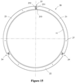
- Figure 15 is a schematic view showing the structure of a reinforcement ring tooling 20 in a fourth mounting state according to the embodiment of the present application
- Figure 16 is a schematic view showing the structure of a reinforcement ring tooling 20 in a fifth mounting state according to the embodiment of the present application.
- a method for mounting the reinforcement ring tooling 20 in the above embodiment includes: a step of providing a separate member, a step of connecting the separate member, and a step of engaging the annular body with the rotor.
- the limiting members 26 are mounted, that is, one set of the two sets of the limiting members 26 is mounted on the outer circumferential surface of the yoke 11, as shown in Figure 12 .
- the axis of the rotor 10 can be placed in a vertical state, and the rotor end cover 12 can be located at the bottom or on the top. In this embodiment, the rotor end cover 12 is located at the bottom.
- the more than two stoppers 261 are circumferentially fixed to the outer circumferential surface of the yoke 11 by the third fastener 262, and more than two stoppers 261 are located on a side close to the rotor end cover 12, so as to mount the reinforcement ring tooling 20 on the side of the rotor 10 close to the rotor end cover 12, thereby better enhancing the structural strength of the rotor 10.
- connection members in the reinforcement ring tooling 20 are all movable connection members, and two of the connection members are the rotation adjusting members 24 and the other connection member is the distance adjusting member 25. Therefore, it is necessary to perform the step of providing the separate members first, and then perform the step of connecting the separate members, as shown in Figure 13 .
- the separate member 21, the separate member 22, and the separate member 23 are provided, the separate member 21 and the separate member 22 are rotatably connected by a set of the rotation adjustment members 24, the separate member 22 and the separate member 23 are rotatably connected by the other set of rotation adjustment members 24.
- the separate member 21 and the separate member 22 are placed oppositely so that the pin holes 241c of the lugs 241 mounted on the separate member 21 and the pin holes 242c of the lugs 242 mounted on the separate member 22 are aligned with each other, the pin shaft 244 is inserted into the pin hole 241c of the convex lug 241 and the pin hole 242c of the convex lug 242.
- one side of the stopping member 245 is inserted into the clamping slot of the pin shaft 244 while abutting against the upper lug plate 241a, and the other side of the stopping member 245 is inserted into the other clamping slot of the pin shaft 244 while abutting against the lower lug plate 241b, and the two stopping member 245 are respectively fixed to the corresponding upper lug plate 241a and lower lug plate 241b by bolts 246, thereby completing the connection of the separate member 21 and the separate member 22, the separate member 23 and the separate member 22 are connected in the same manner.
- the corresponding separate members are connected by a predetermined distance via the distance adjusting member 25, that is, the separate member 21and the separate member 23 are spaced apart by a predetermined distance T2 via the distance adjusting member 25, as shown in Figure 13 .
- a retaining block 254 is provided between the connection end plate 251 mounted to the separate member 21 and the connection end plate 252 mounted to the separate member 22, that is, the retaining block 254 is inserted into the mounting opening between the separate member 21 and the separate member 23, thereby retaining the predetermined distance T2 between the separate member 21 and the separate member 23.
- the connection end plate 251 and the connection end plate 252 are fixedly connected by the first fastener 253, so that the retaining block 254 is clamped between the connection end plate 251 and the connection end plate 252.
- the separate member 21, the separate member 22, and the separate member 23 enclose to form the annular body 20a.
- the annular body 20a composed of the separate member 21, the separate member 22 and the separate member 23 is lifted so that the axis thereof is in a vertical state, coincides with the axis of the rotor 10, and is mounted around the outside of the rotor 10 from top to bottom, and finally the respective one end surfaces in the axial direction of the first curved plate bodies of the separate member 21, the separate member 22, and the separate member 23 are simultaneously in contact with the upper surfaces of the more than two stoppers 261 as shown in Figure 14 .
- the distance between the respective separate members is retained by a predetermined distance T1 by the distance adjusting member 25, so that the annular body 20a is attached to the outer circumferential surface of the yoke 11, as shown in Figure 15 .
- the first fastener 253 is loosened, the retaining block 254 is pulled out from between the connection end plate 251 and the connection end plate 252, and the connection end plate 251 and the connection end plate 252 are gradually brought closer by the first fastener 253 until the annular body 20a is in close contact with the outer circumferential surface of the yoke 11.
- the limiting member 26 is then mounted, that is, the other set of the two sets of the limiting members 26 is mounted to the outer circumferential surface of the yoke 11, as shown in Figure 16 . That is, through the cooperation of the third fastener 262 with the screw holes on the outer circumferential surface of the yoke 11, more than two stoppers 261 of the other set of the limiting members 26 are fixed to the outer circumferential surface of the yoke 11, and the set of the limiting members 26 are located on the other axial side of the annular body 20a.
- the above steps are the process of mounting the reinforcement ring tooling 20 to the rotor 10, and the reinforcement ring tooling 20 can be detached from the rotor 10 in the order from the back to the front and in a reverse operation of the respective steps.
- the steps in the method for mounting the reinforcement ring tooling 20 according to the above embodiment are not specifically defined.
- the three separate members of the reinforcement ring tooling 20 are rotatably connected by the rotation adjusting member 24, since the distance adjustment between the three divided members is impossible, it is required to perform the step of providing the separate member first, and then perform the step of attaching the annular body with the rotor, that is, it is required to retain the three separate members on the outer circumference of the rotor 10 and respectively attached to the outer circumferential circumferential surface of the yoke 11 to form the annular body 20a, and then the three separate members can then be connected two by two by means of three connection members, that is, the three rotation adjusting members 24, thereby completing the final step of connecting the separate members.
- a rotor 10 which includes: a yoke 11, a magnetic pole provided on an inner circumference of the yoke 11, and a reinforcement ring tooling 20 according to any one of the above embodiments, which is mounted on the outer circumference of the yoke 11. Since the rotor 10 according to the present embodiment includes the reinforcement ring tooling 20 of the above embodiment, the rotor 10 has the same advantages as the reinforcement ring tooling 20, which will not be described again.
- an electric machinery which includes: a stator and the rotor 10 of the above embodiment, the rotor 10 is sleeved on the outside of the stator. Since the electric machinery in this embodiment includes the reinforcement ring tooling 20 of the above embodiment, the electric machinery has the same advantages as the reinforcement ring tooling 20, which will not be described again.
Landscapes
- Engineering & Computer Science (AREA)
- Power Engineering (AREA)
- Manufacturing & Machinery (AREA)
- Manufacture Of Motors, Generators (AREA)
- Structures Of Non-Positive Displacement Pumps (AREA)
Claims (18)
- Verstärkungsring (20) zur Befestigung an einem Außenumfang eines Rotors (10) einer elektrischen Maschine, wobei der Verstärkungsring (20) mehr als zwei separate Elemente (21, 22, 23) und mehr als zwei Verbindungselemente umfasst, wobei die mehr als zwei Verbindungselemente den mehr als zwei separaten Elementen (21, 22, 23) zugeordnet sind und die mehr als zwei separaten Elemente (21, 22, 23) einen Ringkörper (20a) bildend über die mehr als zwei Verbindungselemente miteinander verbunden sind,wobei mindestens zwei der mehr als zwei Verbindungselemente bewegliche Verbindungselemente sind, und wobei die entsprechenden separaten Elemente (21, 22, 23) durch die beweglichen Verbindungselemente beweglich miteinander verbunden sind, wodurch es möglich ist, den Verstärkungsring (20) lösbar an den Außenumfang des Rotors (10) anzubringen; unddadurch gekennzeichnet, dassdie beweglichen Verbindungselemente Folgendes umfassen:
ein Dreheinstellelement (24), wobei die entsprechenden separaten Elemente (21, 22, 23) derart verbunden sind, dass die entsprechenden separaten Elemente durch das Dreheinstellelement (24) relativ zueinander drehbar sind; und/oder ein Abstandseinstellelement (25), wobei die entsprechenden separaten Elemente (21, 22, 23) derart verbunden sind, dass es möglich ist, dass die entsprechenden separaten Elemente durch die Abstandseinstellelemente (25) nahe beieinander sind oder entfernt voneinander sind. - Verstärkungsring (20) nach Anspruch 1, wobei die beweglichen Verbindungselemente das Dreheinstellelement (24) umfassen, wobei das Dreheinstellelement (24) einen Stiftschaft (244) und Stiftlöcher (241c, 242c), die jeweils an den entsprechenden separaten Elementen (21, 22, 23) vorgesehen sind, umfasst, und wobei die entsprechenden separaten Elemente (21, 22, 23) durch den durch die Stiftlöcher (241c, 242c) hindurch geführten Stiftschaft (244) drehbar verbunden sind.
- Verstärkungsring (20) nach Anspruch 2, wobei die entsprechenden separaten Elemente (21, 22, 23) jeweils mit einer konvexen Lasche versehen sind und die Stiftlöcher (241c, 242c) an der konvexen Lasche vorgesehen sind.
- Verstärkungsring (20) nach Anspruch 3, wobei das Dreheinstellelement (24) des Weiteren ein Verriegelungselement umfasst, das zum Begrenzen einer axialen Bewegung des Stiftschafts (244) in den Stiftlöchern (241c, 242c) mit dem Stiftschaft (244) in Eingriff steht.
- Verstärkungsring (20) nach Anspruch 4, wobei das Verriegelungselement ein Anschlagelement (245) umfasst, wobei der Stiftschaft (244) entlang einer Außenumfangsfläche mit einem dem Anschlagelement (245) entsprechenden Spannschlitz versehen ist, und wobei der Spannschlitz außerhalb der konvexen Lasche angeordnet ist, wodurch es möglich ist, dass das Anschlagelement (245) in den Spannschlitz eingeführt wird, während es gleichzeitig an der konvexen Lasche anliegt.
- Verstärkungsring (20) nach Anspruch 3, wobei die konvexe Lasche eine obere Laschenplatte (241a, 242a) und eine untere Laschenplatte (241b, 242b) umfasst, wobei die Stiftlöcher (241c, 242c) jeweils in der oberen Laschenplatte (241a, 242a) und der unteren Laschenplatte (241b, 242b) vorgesehen sind, und wobei des Weiteren in mindestens einem der Sitftlöcher der konvexen Lasche eine Haltehülse (243) zur Anlage an und Zusammenwirkung mit dem Stiftschaft (244) über die Haltehülse (243) vorgesehen ist.
- Verstärkungsring (20) nach Anspruch 1, wobei die beweglichen Verbindungselemente das Abstandseinstellelement (25) umfassen, wobei das Abstandseinstellelement (25) zwei Verbindungsendplatten (251, 252) und ein Einstellelement umfasst, wobei die zwei Verbindungsendplatten (251, 252) jeweils an einander gegenüberliegenden Verbindungsenden der entsprechenden separaten Elemente (21, 22, 23) vorgesehen sind, und wobei das Einstellelement zum Einstellen des Abstands zwischen den zwei Verbindungsendplatten (251, 252) jeweils mit den zwei Verbindungsendplatten (251, 252) verbunden ist.
- Verstärkungsring (20) nach Anspruch 7, wobei das Einstellelement einen Halteblock (254) und ein erstes Befestigungselement (253) umfasst und wobei der Halteblock (254) lösbar zwischen den zwei Verbindungsendplatten (251, 252) befestigt ist und durch das durch die zwei Verbindungsendplatten (251, 252) hindurchgeführte erste Befestigungselement (253) zwischen die zwei Verbindungsendplatten (251, 252) geklemmt ist.
- Verstärkungsring (20) nach Anspruch 8, wobei eine Seite jeder der zwei Verbindungsendplatten (251, 252) mit einem Einführschlitz (251a) versehen ist, wobei jede der zwei Verbindungsendplatten (251, 252) mit dem eine Oberfläche aufweisenden Einführschlitz (251a) versehen ist, wobei zwei Oberflächen der zwei Verbindungsendplatten (251, 252) einander gegenüberliegen und derart miteinander zusammenwirken, dass sie eine Befestigungsöffnung ausbilden, und wobei sich die Befestigungsöffnung in einer radialen Richtung des Ringkörpers (20a) erstreckt; und
wobei eine Dicke des Halteblocks (254) gleich einer Breite des Einführschlitzes (251a) an jeder der Verbindungsendplatten (251, 252) ist, wodurch der Halteblock (254) in die Befestigungsöffnung einführbar ist. - Verstärkungsring (20) nach Anspruch 1, wobei die beweglichen Verbindungselemente das Abstandseinstellelement (25) umfassen, wobei das Abstandseinstellelement (25) zwei Verbindungsendplatten (251, 252), eine Führungsschiene und einen Schieber umfasst, wobei die zwei Verbindungsendplatten (251, 252) jeweils an den einander gegenüberliegenden Verbindungsenden der entsprechenden separaten Elemente (21, 22, 23) vorgesehen sind, und wobei eine der zwei Verbindungsendplatten (251, 252) mit der Führungsschiene versehen ist und die andere Verbindungsendplatte mit dem mit der Führungsschiene zusammenwirkenden und entlang der Führungsschiene beweglichen Schieber versehen ist.
- Verstärkungsring (20) nach einem der Ansprüche 1 bis 10, des Weiteren ein Begrenzungselement (26) umfassend, wobei das Begrenzungselement (26) an einer Außenumfangsfläche des Rotors (10) vorgesehen ist und sich in einer radialen Richtung des Rotors (10) derart nach außen erstreckt, dass es mit dem Ringkörper (20a) zusammenwirkt und die Bewegung des Ringkörpers (20a) in der axialen Richtung des Rotors (10) begrenzt.
- Verstärkungsring (20) nach Anspruch 11, wobei der Verstärkungsring (20) zwei Sätze der Begrenzungselemente (26) umfasst, wobei die zwei Sätze der Begrenzungselemente (26) jeweils an zwei Seiten in einer axialen Richtung des Ringkörpers (20a) angeordnet sind.
- Verstärkungsring (20) nach Anspruch 11, wobei das Begrenzungselement (26) Anschlagringe und ein zweites Befestigungselement umfasst, wobei die Anschlagringe durch das zweite Befestigungselement in der Umfangsrichtung kontinuierlich an dem Außenumfang des Rotors (10) angeordnet sind;
oder
wobei das Begrenzungselement (26) mehr als zwei Anschläge (261) und ein den mehr als zwei Anschlägen (261) entsprechendes drittes Befestigungselement (262) umfasst, wobei die mehr als zwei Anschläge (261) jeweils durch die entsprechenden dritten Befestigungselemente (262) an dem Außenumfang des Rotors (10) in der Umfangsrichtung voneinander beabstandet angeordnet sind. - Verstärkungsring (20) nach einem der Ansprüche 1 bis 10, 12 und 13, wobei die separaten Elemente (21, 22, 23) einen ersten gekrümmten Plattenkörper (211, 221), einen zweiten gekrümmten Plattenkörper (212, 222) und ein zwischen dem ersten gekrümmten Plattenkörper (211, 221) und dem zweiten gekrümmten Plattenkörper (212, 222) verbindend angeordnetes Stützelement umfassen, wobei der erste gekrümmte Plattenkörper (211, 221) und der zweite gekrümmte Plattenkörper (212, 222) durch das Stützelement in einem vorbestimmten Abstand voneinander gehalten sind, und wobei die mehr als zwei separaten Elemente (21, 22, 23) durch den jeweiligen ersten gekrümmten Plattenkörper (211, 221) einen Aufnahmeraum umschließen und bilden.
- Rotor (10), ein Joch (11) und einen an einem Innenumfang des Jochs (11) vorgesehenen Magnetpol umfassend, wobei der Rotor (10) des Weiteren den an einem Außenumfang des Jochs (11) befestigten Verstärkungsring (20) nach einem der Ansprüche 1 bis 14 umfasst.
- Elektrische Maschine, den Rotor (10) nach Anspruch 15 umfassend.
- Verfahren zur Befestigung eines Verstärkungsrings an einem Außenumfang eines Rotors (10) einer elektrischen Maschine, folgende Schritte umfassend:Schritt des Bereitstellens separater Elemente: Bereitstellen von mehr als zwei separaten Elementen (21, 22, 23) und von den mehr als zwei separaten Elementen (21, 22, 23) zugeordneten mehr als zwei Verbindungselementen;Schritt des Verbindens der separaten Elemente: Verbinden der mehr als zwei separaten Elemente (21, 22, 23) miteinander durch die mehr als zwei Verbindungselemente derart, dass sie einen Ringkörper (20a) bilden, wobei mindestens zwei der mehr als zwei Verbindungselemente als bewegliche Verbindungselemente ausgebildet sind, wodurch es möglich ist, die entsprechenden separaten Elemente (21, 22, 23) durch die beweglichen Verbindungselemente beweglich miteinander zu verbinden; undSchritt des Anbringens des Ringkörpers an dem Rotor: Befestigen des Ringkörpers (20a) an dem Außenumfang des Rotors (10);dadurch gekennzeichnet, dassdas bewegliche Verbindungselement Folgendes umfasst:ein Dreheinstellelement (24), wobei die entsprechenden separaten Elemente (21, 22, 23) derart verbunden sind, dass die entsprechenden separaten Elemente (21, 22, 23) durch das Dreheinstellelement (24) relativ zueinander drehbar sind; undein Abstandseinstellelement (25), wobei die entsprechenden separaten Elemente (21, 22, 23) derart verbunden sind, dass es möglich ist, dass die entsprechenden separaten Elemente (21, 22, 23) durch die Abstandseinstellelemente (25) nahe beieinander sind oder entfernt voneinander sind.
- Verfahren zur Befestigung eines Verstärkungsrings nach Anspruch 17, wobei der Schritt des Verbindens des Weiteren Folgendes umfasst: Verbinden der entsprechenden separaten Elemente (21, 22, 23) mit einem vorbestimmten Abstand durch das Abstandseinstellelement (25), und
wobei der Schritt des Anbringens des Ringkörpers an dem Rotor des Weiteren Folgendes umfasst: Befestigen des Ringkörpers (20a) an dem Außenumfang des Rotors (10) und Anbringen der entsprechenden separaten Elemente (21, 22, 23) aneinander durch das Abstandseinstellelement (25), wodurch die Außenumfangsfläche des Ringkörpers (20a) an der Außenumfangsfläche des Rotors (10) angebracht wird.
Applications Claiming Priority (2)
| Application Number | Priority Date | Filing Date | Title |
|---|---|---|---|
| CN201810079503.0A CN108336839B (zh) | 2018-01-26 | 2018-01-26 | 转子、电机、加强环工装及其安装方法 |
| PCT/CN2019/072309 WO2019144844A1 (zh) | 2018-01-26 | 2019-01-18 | 转子、电机、加强环工装及其安装方法 |
Publications (3)
| Publication Number | Publication Date |
|---|---|
| EP3637586A1 EP3637586A1 (de) | 2020-04-15 |
| EP3637586A4 EP3637586A4 (de) | 2020-07-29 |
| EP3637586B1 true EP3637586B1 (de) | 2022-02-09 |
Family
ID=62926780
Family Applications (1)
| Application Number | Title | Priority Date | Filing Date |
|---|---|---|---|
| EP19744171.0A Active EP3637586B1 (de) | 2018-01-26 | 2019-01-18 | Rotor, motor, verstärkungsringwerkzeug und montageverfahren dafür |
Country Status (6)
| Country | Link |
|---|---|
| US (1) | US11502565B2 (de) |
| EP (1) | EP3637586B1 (de) |
| CN (1) | CN108336839B (de) |
| AU (1) | AU2019212558B2 (de) |
| ES (1) | ES2907209T3 (de) |
| WO (1) | WO2019144844A1 (de) |
Families Citing this family (3)
| Publication number | Priority date | Publication date | Assignee | Title |
|---|---|---|---|---|
| CN108336839B (zh) * | 2018-01-26 | 2019-08-02 | 北京金风科创风电设备有限公司 | 转子、电机、加强环工装及其安装方法 |
| CN112953053B (zh) * | 2019-12-11 | 2022-11-11 | 新疆金风科技股份有限公司 | 转子的加强装置及转子的套装方法 |
| CN115765265A (zh) * | 2022-11-02 | 2023-03-07 | 浙江联昌电气科技有限公司 | 电机加强环 |
Family Cites Families (11)
| Publication number | Priority date | Publication date | Assignee | Title |
|---|---|---|---|---|
| JPH0777504B2 (ja) * | 1987-11-17 | 1995-08-16 | ファナック株式会社 | 高速インダクション型モータのロータ構造 |
| DE20121078U1 (de) * | 2001-12-21 | 2002-08-22 | Rother, Peter, 71034 Böblingen | Integration einer Positionierungs- und Klebe-Vorrichtung in die Konstruktion von Aussenläufer-Elektromotoren |
| US7661185B2 (en) * | 2006-10-10 | 2010-02-16 | Canopy Technologies, Llc | Method for assembling rotor of permanent magnet motor |
| EP2045464B2 (de) | 2007-10-01 | 2016-08-24 | Siemens Aktiengesellschaft | Windturbinenblattverstelllager |
| CN201771901U (zh) * | 2010-07-01 | 2011-03-23 | 中山大洋电机制造有限公司 | 一种锁紧装置 |
| US20120227536A1 (en) * | 2011-03-10 | 2012-09-13 | General Electric Company | Sectioned tuning ring for rotating body |
| CN202309459U (zh) | 2011-10-27 | 2012-07-04 | 北京万源工业有限公司 | 一种外转子直驱永磁同步风力发电机 |
| JP6087427B2 (ja) * | 2014-10-02 | 2017-03-01 | 三菱電機株式会社 | 回転電機の回転子及び回転電機の回転子の製造方法 |
| TWI554007B (zh) * | 2015-12-31 | 2016-10-11 | With inside and outside of the hollow rotor of motor delineated DC sub-structure | |
| CN108336839B (zh) | 2018-01-26 | 2019-08-02 | 北京金风科创风电设备有限公司 | 转子、电机、加强环工装及其安装方法 |
| CN208142948U (zh) * | 2018-05-03 | 2018-11-23 | 北京金风科创风电设备有限公司 | 转子及风力发电机组 |
-
2018
- 2018-01-26 CN CN201810079503.0A patent/CN108336839B/zh active Active
-
2019
- 2019-01-18 AU AU2019212558A patent/AU2019212558B2/en active Active
- 2019-01-18 EP EP19744171.0A patent/EP3637586B1/de active Active
- 2019-01-18 WO PCT/CN2019/072309 patent/WO2019144844A1/zh not_active Ceased
- 2019-01-18 US US16/630,849 patent/US11502565B2/en active Active
- 2019-01-18 ES ES19744171T patent/ES2907209T3/es active Active
Also Published As
| Publication number | Publication date |
|---|---|
| EP3637586A4 (de) | 2020-07-29 |
| US20200144881A1 (en) | 2020-05-07 |
| ES2907209T3 (es) | 2022-04-22 |
| CN108336839A (zh) | 2018-07-27 |
| AU2019212558A1 (en) | 2020-02-20 |
| CN108336839B (zh) | 2019-08-02 |
| WO2019144844A1 (zh) | 2019-08-01 |
| US11502565B2 (en) | 2022-11-15 |
| EP3637586A1 (de) | 2020-04-15 |
| AU2019212558B2 (en) | 2020-10-22 |
Similar Documents
| Publication | Publication Date | Title |
|---|---|---|
| EP3637586B1 (de) | Rotor, motor, verstärkungsringwerkzeug und montageverfahren dafür | |
| CN109625558B (zh) | 发电机辅助工装、发电机运输方法和装配方法 | |
| EP3754184B1 (de) | Turmsegment, turm, segmentierungsverfahren und windturbine | |
| CN109617274B (zh) | 一种永磁同步电机转子 | |
| AU2018431391B2 (en) | Permanent magnet motor and modular rotor structure thereof | |
| WO2019109588A1 (zh) | 发电机的装配工装以及装配方法 | |
| GB2597615A (en) | Iron core lamination welding assistance apparatus | |
| CN101752917A (zh) | 水轮发电机支架式实心磁轭 | |
| US20070096584A1 (en) | Structure and method of rotor assembly without the hub | |
| CN114465436B (zh) | 斜极可调的电机 | |
| CN111590103B (zh) | 一种专用于车加工电机定子机壳止口的工装夹具 | |
| CN114157060B (zh) | 定子支架、电机定子以及电机 | |
| CA3163072C (en) | DEVICE FOR SEPARATION OR ASSEMBLY OF ELECTRICAL MACHINERY, METHOD FOR SEPARATION OF ELECTRICAL MACHINERY AND METHOD FOR ASSEMBLY OF ELECTRICAL MACHINERY | |
| EP3958440B1 (de) | Statortragwerk und stator | |
| CN211438435U (zh) | 汽车变速箱传动齿轮拉床底座结构 | |
| CN115940534A (zh) | 定子铁芯制造工装及定子铁芯制造方法 | |
| CN221850028U (zh) | 一种直驱式螺旋压力机的转子安装工装 | |
| AU2020413260A1 (en) | Transportation tooling structure, split electric motor module with transportation tooling structure, and transportation method | |
| CN219394618U (zh) | 一种运行高效的吊扇用外转子电机 | |
| CN222433960U (zh) | 一种半直驱风力发电机定子铁心防变形工装 | |
| CN219124073U (zh) | 定子铁芯制造工装 | |
| CA3161942C (en) | Transportation tooling structure, split electric motor module with transportation tooling structure, and transportation method | |
| CN223130952U (zh) | 一种整体式金刚石预铣刀 | |
| CN102332789B (zh) | 一种电动机生产工艺 | |
| CN216372864U (zh) | 一种适用于蜂窝陶瓷载体封孔设备的多工位夹具 |
Legal Events
| Date | Code | Title | Description |
|---|---|---|---|
| STAA | Information on the status of an ep patent application or granted ep patent |
Free format text: STATUS: THE INTERNATIONAL PUBLICATION HAS BEEN MADE |
|
| PUAI | Public reference made under article 153(3) epc to a published international application that has entered the european phase |
Free format text: ORIGINAL CODE: 0009012 |
|
| STAA | Information on the status of an ep patent application or granted ep patent |
Free format text: STATUS: REQUEST FOR EXAMINATION WAS MADE |
|
| 17P | Request for examination filed |
Effective date: 20200109 |
|
| AK | Designated contracting states |
Kind code of ref document: A1 Designated state(s): AL AT BE BG CH CY CZ DE DK EE ES FI FR GB GR HR HU IE IS IT LI LT LU LV MC MK MT NL NO PL PT RO RS SE SI SK SM TR |
|
| AX | Request for extension of the european patent |
Extension state: BA ME |
|
| A4 | Supplementary search report drawn up and despatched |
Effective date: 20200701 |
|
| RIC1 | Information provided on ipc code assigned before grant |
Ipc: H02K 15/02 20060101ALI20200625BHEP Ipc: H02K 1/22 20060101AFI20200625BHEP |
|
| GRAP | Despatch of communication of intention to grant a patent |
Free format text: ORIGINAL CODE: EPIDOSNIGR1 |
|
| STAA | Information on the status of an ep patent application or granted ep patent |
Free format text: STATUS: GRANT OF PATENT IS INTENDED |
|
| DAV | Request for validation of the european patent (deleted) | ||
| DAX | Request for extension of the european patent (deleted) | ||
| INTG | Intention to grant announced |
Effective date: 20210219 |
|
| GRAJ | Information related to disapproval of communication of intention to grant by the applicant or resumption of examination proceedings by the epo deleted |
Free format text: ORIGINAL CODE: EPIDOSDIGR1 |
|
| STAA | Information on the status of an ep patent application or granted ep patent |
Free format text: STATUS: REQUEST FOR EXAMINATION WAS MADE |
|
| INTC | Intention to grant announced (deleted) | ||
| GRAP | Despatch of communication of intention to grant a patent |
Free format text: ORIGINAL CODE: EPIDOSNIGR1 |
|
| STAA | Information on the status of an ep patent application or granted ep patent |
Free format text: STATUS: GRANT OF PATENT IS INTENDED |
|
| INTG | Intention to grant announced |
Effective date: 20210906 |
|
| GRAS | Grant fee paid |
Free format text: ORIGINAL CODE: EPIDOSNIGR3 |
|
| GRAA | (expected) grant |
Free format text: ORIGINAL CODE: 0009210 |
|
| STAA | Information on the status of an ep patent application or granted ep patent |
Free format text: STATUS: THE PATENT HAS BEEN GRANTED |
|
| AK | Designated contracting states |
Kind code of ref document: B1 Designated state(s): AL AT BE BG CH CY CZ DE DK EE ES FI FR GB GR HR HU IE IS IT LI LT LU LV MC MK MT NL NO PL PT RO RS SE SI SK SM TR |
|
| REG | Reference to a national code |
Ref country code: GB Ref legal event code: FG4D |
|
| REG | Reference to a national code |
Ref country code: CH Ref legal event code: EP Ref country code: AT Ref legal event code: REF Ref document number: 1468106 Country of ref document: AT Kind code of ref document: T Effective date: 20220215 |
|
| REG | Reference to a national code |
Ref country code: IE Ref legal event code: FG4D |
|
| REG | Reference to a national code |
Ref country code: DE Ref legal event code: R096 Ref document number: 602019011532 Country of ref document: DE |
|
| REG | Reference to a national code |
Ref country code: ES Ref legal event code: FG2A Ref document number: 2907209 Country of ref document: ES Kind code of ref document: T3 Effective date: 20220422 |
|
| REG | Reference to a national code |
Ref country code: LT Ref legal event code: MG9D |
|
| REG | Reference to a national code |
Ref country code: NL Ref legal event code: MP Effective date: 20220209 |
|
| REG | Reference to a national code |
Ref country code: GR Ref legal event code: EP Ref document number: 20220400930 Country of ref document: GR Effective date: 20220608 |
|
| REG | Reference to a national code |
Ref country code: AT Ref legal event code: MK05 Ref document number: 1468106 Country of ref document: AT Kind code of ref document: T Effective date: 20220209 |
|
| PG25 | Lapsed in a contracting state [announced via postgrant information from national office to epo] |
Ref country code: SE Free format text: LAPSE BECAUSE OF FAILURE TO SUBMIT A TRANSLATION OF THE DESCRIPTION OR TO PAY THE FEE WITHIN THE PRESCRIBED TIME-LIMIT Effective date: 20220209 Ref country code: RS Free format text: LAPSE BECAUSE OF FAILURE TO SUBMIT A TRANSLATION OF THE DESCRIPTION OR TO PAY THE FEE WITHIN THE PRESCRIBED TIME-LIMIT Effective date: 20220209 Ref country code: PT Free format text: LAPSE BECAUSE OF FAILURE TO SUBMIT A TRANSLATION OF THE DESCRIPTION OR TO PAY THE FEE WITHIN THE PRESCRIBED TIME-LIMIT Effective date: 20220609 Ref country code: NO Free format text: LAPSE BECAUSE OF FAILURE TO SUBMIT A TRANSLATION OF THE DESCRIPTION OR TO PAY THE FEE WITHIN THE PRESCRIBED TIME-LIMIT Effective date: 20220509 Ref country code: NL Free format text: LAPSE BECAUSE OF FAILURE TO SUBMIT A TRANSLATION OF THE DESCRIPTION OR TO PAY THE FEE WITHIN THE PRESCRIBED TIME-LIMIT Effective date: 20220209 Ref country code: LT Free format text: LAPSE BECAUSE OF FAILURE TO SUBMIT A TRANSLATION OF THE DESCRIPTION OR TO PAY THE FEE WITHIN THE PRESCRIBED TIME-LIMIT Effective date: 20220209 Ref country code: HR Free format text: LAPSE BECAUSE OF FAILURE TO SUBMIT A TRANSLATION OF THE DESCRIPTION OR TO PAY THE FEE WITHIN THE PRESCRIBED TIME-LIMIT Effective date: 20220209 Ref country code: BG Free format text: LAPSE BECAUSE OF FAILURE TO SUBMIT A TRANSLATION OF THE DESCRIPTION OR TO PAY THE FEE WITHIN THE PRESCRIBED TIME-LIMIT Effective date: 20220509 |
|
| PG25 | Lapsed in a contracting state [announced via postgrant information from national office to epo] |
Ref country code: PL Free format text: LAPSE BECAUSE OF FAILURE TO SUBMIT A TRANSLATION OF THE DESCRIPTION OR TO PAY THE FEE WITHIN THE PRESCRIBED TIME-LIMIT Effective date: 20220209 Ref country code: LV Free format text: LAPSE BECAUSE OF FAILURE TO SUBMIT A TRANSLATION OF THE DESCRIPTION OR TO PAY THE FEE WITHIN THE PRESCRIBED TIME-LIMIT Effective date: 20220209 Ref country code: FI Free format text: LAPSE BECAUSE OF FAILURE TO SUBMIT A TRANSLATION OF THE DESCRIPTION OR TO PAY THE FEE WITHIN THE PRESCRIBED TIME-LIMIT Effective date: 20220209 Ref country code: AT Free format text: LAPSE BECAUSE OF FAILURE TO SUBMIT A TRANSLATION OF THE DESCRIPTION OR TO PAY THE FEE WITHIN THE PRESCRIBED TIME-LIMIT Effective date: 20220209 |
|
| PG25 | Lapsed in a contracting state [announced via postgrant information from national office to epo] |
Ref country code: IS Free format text: LAPSE BECAUSE OF FAILURE TO SUBMIT A TRANSLATION OF THE DESCRIPTION OR TO PAY THE FEE WITHIN THE PRESCRIBED TIME-LIMIT Effective date: 20220609 |
|
| PG25 | Lapsed in a contracting state [announced via postgrant information from national office to epo] |
Ref country code: SM Free format text: LAPSE BECAUSE OF FAILURE TO SUBMIT A TRANSLATION OF THE DESCRIPTION OR TO PAY THE FEE WITHIN THE PRESCRIBED TIME-LIMIT Effective date: 20220209 Ref country code: SK Free format text: LAPSE BECAUSE OF FAILURE TO SUBMIT A TRANSLATION OF THE DESCRIPTION OR TO PAY THE FEE WITHIN THE PRESCRIBED TIME-LIMIT Effective date: 20220209 Ref country code: RO Free format text: LAPSE BECAUSE OF FAILURE TO SUBMIT A TRANSLATION OF THE DESCRIPTION OR TO PAY THE FEE WITHIN THE PRESCRIBED TIME-LIMIT Effective date: 20220209 Ref country code: EE Free format text: LAPSE BECAUSE OF FAILURE TO SUBMIT A TRANSLATION OF THE DESCRIPTION OR TO PAY THE FEE WITHIN THE PRESCRIBED TIME-LIMIT Effective date: 20220209 Ref country code: DK Free format text: LAPSE BECAUSE OF FAILURE TO SUBMIT A TRANSLATION OF THE DESCRIPTION OR TO PAY THE FEE WITHIN THE PRESCRIBED TIME-LIMIT Effective date: 20220209 Ref country code: CZ Free format text: LAPSE BECAUSE OF FAILURE TO SUBMIT A TRANSLATION OF THE DESCRIPTION OR TO PAY THE FEE WITHIN THE PRESCRIBED TIME-LIMIT Effective date: 20220209 |
|
| REG | Reference to a national code |
Ref country code: DE Ref legal event code: R097 Ref document number: 602019011532 Country of ref document: DE |
|
| PG25 | Lapsed in a contracting state [announced via postgrant information from national office to epo] |
Ref country code: AL Free format text: LAPSE BECAUSE OF FAILURE TO SUBMIT A TRANSLATION OF THE DESCRIPTION OR TO PAY THE FEE WITHIN THE PRESCRIBED TIME-LIMIT Effective date: 20220209 |
|
| PLBE | No opposition filed within time limit |
Free format text: ORIGINAL CODE: 0009261 |
|
| STAA | Information on the status of an ep patent application or granted ep patent |
Free format text: STATUS: NO OPPOSITION FILED WITHIN TIME LIMIT |
|
| 26N | No opposition filed |
Effective date: 20221110 |
|
| PG25 | Lapsed in a contracting state [announced via postgrant information from national office to epo] |
Ref country code: SI Free format text: LAPSE BECAUSE OF FAILURE TO SUBMIT A TRANSLATION OF THE DESCRIPTION OR TO PAY THE FEE WITHIN THE PRESCRIBED TIME-LIMIT Effective date: 20220209 |
|
| REG | Reference to a national code |
Ref country code: DE Ref legal event code: R119 Ref document number: 602019011532 Country of ref document: DE |
|
| REG | Reference to a national code |
Ref country code: CH Ref legal event code: PL |
|
| GBPC | Gb: european patent ceased through non-payment of renewal fee |
Effective date: 20230118 |
|
| PG25 | Lapsed in a contracting state [announced via postgrant information from national office to epo] |
Ref country code: LU Free format text: LAPSE BECAUSE OF NON-PAYMENT OF DUE FEES Effective date: 20230118 |
|
| REG | Reference to a national code |
Ref country code: BE Ref legal event code: MM Effective date: 20230131 |
|
| PG25 | Lapsed in a contracting state [announced via postgrant information from national office to epo] |
Ref country code: LI Free format text: LAPSE BECAUSE OF NON-PAYMENT OF DUE FEES Effective date: 20230131 Ref country code: GB Free format text: LAPSE BECAUSE OF NON-PAYMENT OF DUE FEES Effective date: 20230118 Ref country code: DE Free format text: LAPSE BECAUSE OF NON-PAYMENT OF DUE FEES Effective date: 20230801 Ref country code: CH Free format text: LAPSE BECAUSE OF NON-PAYMENT OF DUE FEES Effective date: 20230131 |
|
| PG25 | Lapsed in a contracting state [announced via postgrant information from national office to epo] |
Ref country code: FR Free format text: LAPSE BECAUSE OF NON-PAYMENT OF DUE FEES Effective date: 20230131 Ref country code: BE Free format text: LAPSE BECAUSE OF NON-PAYMENT OF DUE FEES Effective date: 20230131 |
|
| PG25 | Lapsed in a contracting state [announced via postgrant information from national office to epo] |
Ref country code: IE Free format text: LAPSE BECAUSE OF NON-PAYMENT OF DUE FEES Effective date: 20230118 |
|
| PG25 | Lapsed in a contracting state [announced via postgrant information from national office to epo] |
Ref country code: MC Free format text: LAPSE BECAUSE OF FAILURE TO SUBMIT A TRANSLATION OF THE DESCRIPTION OR TO PAY THE FEE WITHIN THE PRESCRIBED TIME-LIMIT Effective date: 20220209 |
|
| PG25 | Lapsed in a contracting state [announced via postgrant information from national office to epo] |
Ref country code: MC Free format text: LAPSE BECAUSE OF FAILURE TO SUBMIT A TRANSLATION OF THE DESCRIPTION OR TO PAY THE FEE WITHIN THE PRESCRIBED TIME-LIMIT Effective date: 20220209 |
|
| PGFP | Annual fee paid to national office [announced via postgrant information from national office to epo] |
Ref country code: ES Payment date: 20250211 Year of fee payment: 7 |
|
| PGFP | Annual fee paid to national office [announced via postgrant information from national office to epo] |
Ref country code: IT Payment date: 20241210 Year of fee payment: 7 |
|
| PGFP | Annual fee paid to national office [announced via postgrant information from national office to epo] |
Ref country code: TR Payment date: 20250109 Year of fee payment: 7 |
|
| PG25 | Lapsed in a contracting state [announced via postgrant information from national office to epo] |
Ref country code: CY Free format text: LAPSE BECAUSE OF FAILURE TO SUBMIT A TRANSLATION OF THE DESCRIPTION OR TO PAY THE FEE WITHIN THE PRESCRIBED TIME-LIMIT; INVALID AB INITIO Effective date: 20190118 |
|
| PG25 | Lapsed in a contracting state [announced via postgrant information from national office to epo] |
Ref country code: HU Free format text: LAPSE BECAUSE OF FAILURE TO SUBMIT A TRANSLATION OF THE DESCRIPTION OR TO PAY THE FEE WITHIN THE PRESCRIBED TIME-LIMIT; INVALID AB INITIO Effective date: 20190118 |
|
| PGFP | Annual fee paid to national office [announced via postgrant information from national office to epo] |
Ref country code: GR Payment date: 20251210 Year of fee payment: 8 |