EP3636469B1 - Lufteinlassvorrichtung für klimatisierungseinheit eines fahrzeugs - Google Patents
Lufteinlassvorrichtung für klimatisierungseinheit eines fahrzeugs Download PDFInfo
- Publication number
- EP3636469B1 EP3636469B1 EP19201378.7A EP19201378A EP3636469B1 EP 3636469 B1 EP3636469 B1 EP 3636469B1 EP 19201378 A EP19201378 A EP 19201378A EP 3636469 B1 EP3636469 B1 EP 3636469B1
- Authority
- EP
- European Patent Office
- Prior art keywords
- air inlet
- recirculation
- flap
- drum
- flaps
- Prior art date
- Legal status (The legal status is an assumption and is not a legal conclusion. Google has not performed a legal analysis and makes no representation as to the accuracy of the status listed.)
- Active
Links
Images


Classifications
-
- B—PERFORMING OPERATIONS; TRANSPORTING
- B60—VEHICLES IN GENERAL
- B60H—ARRANGEMENTS OF HEATING, COOLING, VENTILATING OR OTHER AIR-TREATING DEVICES SPECIALLY ADAPTED FOR PASSENGER OR GOODS SPACES OF VEHICLES
- B60H1/00—Heating, cooling or ventilating devices
- B60H1/00642—Control systems or circuits; Control members or indication devices for heating, cooling or ventilating devices
- B60H1/00814—Control systems or circuits characterised by their output, for controlling particular components of the heating, cooling or ventilating installation
- B60H1/00821—Control systems or circuits characterised by their output, for controlling particular components of the heating, cooling or ventilating installation the components being ventilating, air admitting or air distributing devices
- B60H1/00864—Ventilators and damper doors
-
- B—PERFORMING OPERATIONS; TRANSPORTING
- B60—VEHICLES IN GENERAL
- B60H—ARRANGEMENTS OF HEATING, COOLING, VENTILATING OR OTHER AIR-TREATING DEVICES SPECIALLY ADAPTED FOR PASSENGER OR GOODS SPACES OF VEHICLES
- B60H1/00—Heating, cooling or ventilating devices
- B60H1/00642—Control systems or circuits; Control members or indication devices for heating, cooling or ventilating devices
- B60H1/00664—Construction or arrangement of damper doors
- B60H1/00671—Damper doors moved by rotation; Grilles
- B60H1/00685—Damper doors moved by rotation; Grilles the door being a rotating disc or cylinder or part thereof
-
- B—PERFORMING OPERATIONS; TRANSPORTING
- B60—VEHICLES IN GENERAL
- B60H—ARRANGEMENTS OF HEATING, COOLING, VENTILATING OR OTHER AIR-TREATING DEVICES SPECIALLY ADAPTED FOR PASSENGER OR GOODS SPACES OF VEHICLES
- B60H1/00—Heating, cooling or ventilating devices
- B60H1/00485—Valves for air-conditioning devices, e.g. thermostatic valves
-
- B—PERFORMING OPERATIONS; TRANSPORTING
- B60—VEHICLES IN GENERAL
- B60H—ARRANGEMENTS OF HEATING, COOLING, VENTILATING OR OTHER AIR-TREATING DEVICES SPECIALLY ADAPTED FOR PASSENGER OR GOODS SPACES OF VEHICLES
- B60H1/00—Heating, cooling or ventilating devices
- B60H1/00642—Control systems or circuits; Control members or indication devices for heating, cooling or ventilating devices
- B60H1/00814—Control systems or circuits characterised by their output, for controlling particular components of the heating, cooling or ventilating installation
- B60H1/00821—Control systems or circuits characterised by their output, for controlling particular components of the heating, cooling or ventilating installation the components being ventilating, air admitting or air distributing devices
- B60H1/00835—Damper doors, e.g. position control
- B60H1/00849—Damper doors, e.g. position control for selectively commanding the induction of outside or inside air
-
- B—PERFORMING OPERATIONS; TRANSPORTING
- B60—VEHICLES IN GENERAL
- B60H—ARRANGEMENTS OF HEATING, COOLING, VENTILATING OR OTHER AIR-TREATING DEVICES SPECIALLY ADAPTED FOR PASSENGER OR GOODS SPACES OF VEHICLES
- B60H1/00—Heating, cooling or ventilating devices
- B60H1/24—Ventilating devices where the heating or cooling is irrelevant
- B60H1/248—Air-extractors, air-evacuation from the vehicle interior
-
- B—PERFORMING OPERATIONS; TRANSPORTING
- B60—VEHICLES IN GENERAL
- B60H—ARRANGEMENTS OF HEATING, COOLING, VENTILATING OR OTHER AIR-TREATING DEVICES SPECIALLY ADAPTED FOR PASSENGER OR GOODS SPACES OF VEHICLES
- B60H1/00—Heating, cooling or ventilating devices
- B60H1/24—Ventilating devices where the heating or cooling is irrelevant
- B60H1/26—Ventilating openings in vehicle exterior; Ducts for conveying ventilating air
-
- B—PERFORMING OPERATIONS; TRANSPORTING
- B60—VEHICLES IN GENERAL
- B60H—ARRANGEMENTS OF HEATING, COOLING, VENTILATING OR OTHER AIR-TREATING DEVICES SPECIALLY ADAPTED FOR PASSENGER OR GOODS SPACES OF VEHICLES
- B60H1/00—Heating, cooling or ventilating devices
- B60H1/00507—Details, e.g. mounting arrangements, desaeration devices
- B60H2001/006—Noise reduction
-
- B—PERFORMING OPERATIONS; TRANSPORTING
- B60—VEHICLES IN GENERAL
- B60H—ARRANGEMENTS OF HEATING, COOLING, VENTILATING OR OTHER AIR-TREATING DEVICES SPECIALLY ADAPTED FOR PASSENGER OR GOODS SPACES OF VEHICLES
- B60H1/00—Heating, cooling or ventilating devices
- B60H1/00642—Control systems or circuits; Control members or indication devices for heating, cooling or ventilating devices
- B60H1/00664—Construction or arrangement of damper doors
- B60H2001/00707—Details of pivots of damper doors
Definitions
- the present invention relates to an air intake device for an air conditioning unit of a vehicle.
- Devices of this type are coupled to the air inlet of the air conditioning unit fan, and are connected to the external air intakes of the vehicle and to the air recirculation pipe in the passenger compartment of the vehicle to selectively allow the entry of fresh air or recirculation air to the fan.
- the recirculation air inlet Since in a vehicle the fresh air inlet must face forward to allow an easy transfer of the outside air from the external sockets towards the air conditioning unit, the recirculation air inlet is generally turned backwards towards the passenger compartment, and therefore can be an important means of spreading the noise generated by the fan and by the operation of the air conditioning unit.
- An object of the present invention is to propose solutions for increasing the efficiency of the air-conditioning unit and reducing the noise perceived inside the passenger compartment of the vehicle and generated by the operation of this unit.
- an air intake device for an air conditioning unit of a vehicle comprising
- the angular span of the recirculation air inlet can be increased. This means that with the same air flow rate the speed of the incoming air flow can be reduced. Furthermore, it is possible to modulate the transition from the extreme fresh air position to the extreme recirculation position.
- a noise damping grille mounted to the casing.
- This noise damping grille has a plurality of openings, each opening having walls parallel to each other and parallel to the walls of the other openings. This expedient allows to further reduce the noise, thanks to the reflection and the reciprocal interference of the sound waves achieved due to the walls of the openings of the damping grille.
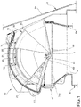
- FIG. 1 an air intake device is indicated as a whole with reference numeral 10.
- the device 10 is shown installed on a vehicle.
- FIG. 2 show a firewall 2, which separates the engine compartment of the vehicle (in the figures, to the left of the wall 2) from the passenger compartment of the vehicle (to the right in the figures).
- an aperture 2a is obtained, through which fresh air coming from external air intakes (not shown) arranged at the engine compartment can reach the air intake device 10.
- the air intake device is coupled to an air conditioning unit 4 of the vehicle, a part of the wall whereof is shown in figures 1-3.
- Figures 1-3 also show an air inlet 4a of the air-conditioning unit, downstream of which an electric fan (not shown) is arranged for air circulation.
- the air intake device 10 comprises a casing 11 which encloses a chamber, which is in communication with the outside of the casing 11 through a fresh air inlet 12, a recirculation air inlet 13 and an air outlet 14.
- the fresh air inlet 12 is in fluid communication with the external air intakes, through the aperture 2a formed in the firewall 2.
- the recirculation air inlet 13 is in fluid communication with a pipe (not shown) for the air recirculation inside the vehicle passenger compartment.
- the air outlet 14 is coupled to the air inlet 4a of the air conditioning unit 4.
- an air filter 14a is arranged, drawn with a dashed line in figure 1 and for clarity omitted in the subsequent figures.
- the air intake device 10 comprises a pair of drum flaps, indicated with reference numerals 20 and 30 in the figures.
- the drum flaps 20, 30 are mounted to the casing 11 rotatably around a same axis of rotation y orthogonal to the plane of the drawing in figures 1-3 .
- the one indicated with 20 will be designated hereinafter as the driving flap and is arranged radially more inward
- that indicated with 30 will be designated as a driven flap and is arranged radially more outward.
- each of the flaps 20, 30 consists of a monolithic body of plastic material, comprising a pair of lateral arms through which the flap is hingedly connected to the casing 11, and an intermediate connection portion which interconnects the side arms.
- the driving flap 20 is coupled to an actuator and/or to a movement mechanism (not shown) configured to adjust the angular position of the driving flap 20.
- the driving flap 20 is operatively connected to the driven flap 30 by elastic means 40.
- these elastic means may consist of a torsion spring having an end 42 coupled to the driving flap 20 and an end 43 coupled to the driven flap 30, and represented in a simplified manner in figures 1-3 . Through the torsion spring 40, the driving flap 20 is able to drive the driven flap 30 into rotation.
- the drum flaps 20, 30 can be moved between an extreme fresh air position (shown in figure 2 ), in which the drum flaps 20, 30 maximize the fluid communication between the fresh air inlet 12 and the air outlet 14 and prevent fluid communication between the recirculation air inlet 13 and the air outlet 14, and an extreme recirculation position (shown in figure 3 ), in which the drum flaps 20, 30 maximize the fluid communication between the recirculation air inlet 13 and air outlet 14 and prevent fluid communication between the fresh air inlet 12 and the air outlet 14.
- an extreme fresh air position shown in figure 2
- the drum flaps 20, 30 maximize the fluid communication between the fresh air inlet 12 and the air outlet 14 and prevent fluid communication between the recirculation air inlet 13 and the air outlet 14
- an extreme recirculation position shown in figure 3
- the drum flaps 20, 30 have substantially the same angular span.
- angular span of an element means the angular extension of the element under consideration, measured with respect to the axis of rotation y which defines the vertex of the angle. More generally, whenever an angle or angular direction is referred to, this angular angle or direction will refer to a vertex coincident with the rotation axis y. Similarly, a radial direction will be a direction orthogonal to the rotation axis y.
- striking means which comprise, on the driving flap 20, a pair of projections 21, 22 formed at angularly opposite ends of the driving flap 20 and extending radially from the driving flap 20 towards the driven flap 30.
- projections 21 and 22 there are respectively a first and a second abutment surface, respectively 21a and 22a.
- the abutment means comprise a projection 31 extending radially from the driven flap 30 towards the driving flap 20.
- a third and a fourth abutment surface respectively 31a and 31b. The angular distance between the third abutment surface 31a and the fourth abutment surface 31b is less than the angular distance between the first abutment surface 21a and the second abutment surface 22a.
- the driven flap 30 also has a pair of projections 32, 33 extending radially outwards from the driven flap 30 and arranged at angularly opposite ends of the driven flap 30.
- the fifth and sixth abutment surfaces 32a and 33a are adapted to engage a stop 15 formed on the casing 11 and arranged between the fresh air inlet 12 and the recirculation air inlet 13.
- the angular span of the recirculated air inlet 13 is partly covered by the driving flap 20 and partly covered by the driven flap 30.
- the flaps 20, 30 are partially overlapping one another.
- one of the projections, 21, of the driving flap 20 is in abutment against an edge of the recirculation air inlet 13 away from the stop 15.
- the second abutment surface 22a of the driving flap 20 abuts against the fourth abutment surface 31b of the driven flap 30, while the sixth abutment surface 33a of the driven flap 30 abuts against the stop 15.
- the driving flap 20 When the first abutment surface 21a of the driving flap 20 comes into abutment against the third abutment surface 31a of the driven flap 30, the driving flap 20 begins to drag the driven flap 30 with it. In this way, the recirculation air inlet 13 continues to open progressively towards the extreme recirculation position, while the fresh air inlet 12 begins to close progressively towards the extreme recirculation position.
- the driven flap 30 stops while the driving flap 20 can continue the rotation movement against the action of the spring 40 which is compressed.
- the rotating movement of the driven flap stops when the first abutment surface 21a of the driving flap 20 comes into contact with the third abutment surface 31a of the driven flap 30 and the projections 22 of the driving flap 20 abuts against the edge of the fresh air inlet 12 away from the stop 15.
- the extreme recirculation position shown in figure 3 is then reached. In this extreme position, the angular span of the fresh air inlet 12 is completely covered by the driven flap 30, and the drum flaps 20, 30 are completely superimposed on each other.
- a noise damping grille 40 mounted to the casing 11.
- This noise damping grille 40 has a plurality of apertures 41.
- Each aperture 41 is delimited by wall surfaces parallel to each other, so that each aperture has a substantially prismatic shape. Furthermore, the wall surfaces of each aperture 41 are parallel to the wall surfaces of the other apertures 41.
- the recirculation air inlet 13 may comprise a main air inlet 13a oriented in radial direction and at least one secondary air inlet 13b oriented in a direction orthogonal to the radial direction.
- At least one deflecting cap is mounted to the casing at at least one of said main air inlet 13a and secondary air inlets 13b.
- a single deflecting cap may be provided which covers the main air inlet 13a and secondary air inlets 13b.
- the deflecting cap 50 defines a duct having an inlet port 50a oriented towards the fresh air opening 12 (i.e. towards the engine compartment) and an outlet port coinciding with the respective recirculation air inlet, 13a and/or 13b, of the device 10.
Landscapes
- Physics & Mathematics (AREA)
- Thermal Sciences (AREA)
- Engineering & Computer Science (AREA)
- Mechanical Engineering (AREA)
- Air-Conditioning For Vehicles (AREA)
Claims (11)
- Luftaufnahmevorrichtung für eine Klimaanlageneinheit eines Fahrzeugs, mit
einem Gehäuse (11), auf dem ein Frischlufteinlass (12), ein Rezirkulationslufteinlass (13) und ein Luftauslass (14), der dazu angepasst ist, mit einem Lufteinlass (4a) eines Gebläses einer Klimaanlageneinheit assoziiert zu werden, ausgebildet sind, und
einem Paar Trommelklappen (20, 30), die an dem Gehäuse (11) in einer um eine gemeinsame Drehachse (y) drehbaren Weise montiert sind und zwischen einer Frischluftextremposition, in der die Trommelklappen (20, 30) eine Fluidverbindung zwischen dem Frischlufteinlass (12) und dem Luftauslass (14) maximieren und eine Fluidverbindung zwischen dem Rezirkulationslufteinlass (13) und dem Luftauslass (14) verhindern, und einer Rezirkulationsextremposition, in der die Trommelklappen (20, 30) eine Fluidverbindung zwischen dem Rezirkulationslufteinlass (13) und dem Luftauslass (14) maximieren und eine Fluidverbindung zwischen dem Frischlufteinlass (12) und dem Luftauslass (14) verhindern, bewegbar sind, bei der zwischen den Trommelklappen (20, 30) ein elastisches Mittel (40) eingefügt ist, mittels dessen eine der Trommelklappen (20) imstande ist, die andere der Trommelklappen (30) während einer Drehbewegung der Trommelklappen (20, 30) zwischen der Frischluftextremposition und der Rezirkulationsextremposition anzutreiben,
dadurch gekennzeichnet, dass in der Frischluftextremposition die Winkelspanne des Rezirkulationslufteinlasses (13) durch eine der Trommelklappen (20) teilweise bedeckt und durch die andere der Trommelklappen (30) teilweise bedeckt ist, und in der Rezirkulationsextremposition die Winkelspanne des Frischlufteinlasses (12) durch eine der Trommelklappen (30) vollständig bedeckt ist, welche Trommelklappen (20, 30) einander überlappen. - Vorrichtung nach Anspruch 1, bei der zwischen den Trommelklappen ein Anlagemittel eingefügt ist, bei der bei einer besagter Trommelklappen, nachfolgend antreibende Klappe (20), besagtes Anlagemittel erste und zweite Anlageoberflächen (21a, 22a), die auf hinsichtlich eines Winkels entgegengesetzten Enden der Trommelklappe angeordnet sind, aufweist, und bei der anderen besagter Trommelklappen, nachfolgend angetriebene Klappe (30), besagtes Anlagemittel dritte und vierte Anlageoberflächen (31a, 31b), die auf jeweiligen verschiedenen Winkelpositionen der Trommelklappe angeordnet sind, aufweist, und bei der ein Winkelabstand zwischen der dritten und der vierten Anlageoberfläche (31a, 31b) geringer als ein Abstand zwischen der ersten und der zweiten Anlageoberfläche (21a, 22a) ist.
- Vorrichtung nach Anspruch 2, bei der besagtes Anlagemittel auf Vorsprüngen (21, 22, 31), die auf jeder der Trommelklappen ausgebildet sind, und die in Richtung der anderen der Trommelklappen radial vorstehen, angeordnet ist.
- Vorrichtung nach Anspruch 2 oder 3, bei der die antreibende Klappe (20) eine Klappe ist, die radial einwärts angeordnet ist, und die angetriebene Klappe (30) eine Klappe ist, die radial auswärts angeordnet ist.
- Vorrichtung nach Anspruch 4, bei der die angetriebene Klappe (30) ferner fünfte und sechste Anlageoberflächen (32a, 33a), die sich radial nach außen erstrecken und auf hinsichtlich eines Winkels entgegengesetzten Enden der angetriebenen Klappe (30) angeordnet sind, aufweist, bei der auf dem Gehäuse (11) ein Anschlag (15), der zwischen dem Frischlufteinlass (12) und dem Rezirkulationslufteinlass (13) angeordnet ist, ausgebildet ist, der durch die fünfte Anlageoberfläche (32a) und durch die sechste Anlageoberfläche (33a) in der Rezirkulationsextremposition bzw. in der Frischluftextremposition in Eingriff bringbar ist.
- Vorrichtung nach einem der vorhergehenden Ansprüche, bei der die Trommelklappen (20, 30) im Wesentlichen dieselbe Winkelspanne aufweisen.
- Vorrichtung nach einem der vorhergehenden Ansprüche, bei der besagtes elastisches Mittel eine Torsionsfeder aufweist.
- Vorrichtung nach einem der vorhergehenden Ansprüche, bei der an dem Rezirkulationslufteinlass (13) ein Geräuschdämpfungsgrill (40), der an dem Gehäuse (11) montiert ist, angeordnet ist.
- Vorrichtung nach Anspruch 8, bei der der Geräuschdämpfungsgrill (40) eine Mehrzahl von Öffnungen (41), bei denen jede Öffnung (41) durch Wandoberflächen parallel zueinander und parallel zu den Wandoberflächen der anderen Öffnungen (41) begrenzt ist, aufweist.
- Vorrichtung nach einem der vorhergehenden Ansprüche, bei der der Rezirkulationslufteinlass (13) einen Hauptlufteinlass (13a), der in radialer Richtung orientiert ist, und mindestens einen sekundären Lufteinlass (13b), der in einer Richtung orthogonal zu der radialen Richtung orientiert ist, aufweist.
- Vorrichtung nach Anspruch 10, mit mindestens einer Ablenkungskappe (50), die an dem Gehäuse (11) an mindestens einem von besagtem Hauptlufteinlass und sekundären Lufteinlass montiert ist, die einen Kanal definiert, der eine Einlassöffnung (50a), die in Richtung des Frischlufteinlasses (12) orientiert ist, und eine Auslassöffnung, die mit mindestens einem von besagtem Hauptlufteinlass und sekundären Lufteinlass zusammenfällt, aufweist.
Applications Claiming Priority (1)
| Application Number | Priority Date | Filing Date | Title |
|---|---|---|---|
| IT102018000009234A IT201800009234A1 (it) | 2018-10-08 | 2018-10-08 | Dispositivo di presa aria per un’unità di climatizzazione di un veicolo. |
Publications (2)
| Publication Number | Publication Date |
|---|---|
| EP3636469A1 EP3636469A1 (de) | 2020-04-15 |
| EP3636469B1 true EP3636469B1 (de) | 2021-07-21 |
Family
ID=64902236
Family Applications (1)
| Application Number | Title | Priority Date | Filing Date |
|---|---|---|---|
| EP19201378.7A Active EP3636469B1 (de) | 2018-10-08 | 2019-10-04 | Lufteinlassvorrichtung für klimatisierungseinheit eines fahrzeugs |
Country Status (4)
| Country | Link |
|---|---|
| US (1) | US11186140B2 (de) |
| EP (1) | EP3636469B1 (de) |
| ES (1) | ES2884129T3 (de) |
| IT (1) | IT201800009234A1 (de) |
Families Citing this family (3)
| Publication number | Priority date | Publication date | Assignee | Title |
|---|---|---|---|---|
| IT201800009130A1 (it) * | 2018-10-03 | 2020-04-03 | Denso Thermal Systems Spa | Dispositivo di distribuzione aria posteriore per un’unità di climatizzazione di un autoveicolo. |
| US20220194169A1 (en) * | 2020-12-17 | 2022-06-23 | Denso International America, Inc. | Door Assembly and HVAC System Having the Same |
| KR20230036278A (ko) * | 2021-09-07 | 2023-03-14 | 현대자동차주식회사 | 차량용 공조 장치 |
Family Cites Families (11)
| Publication number | Priority date | Publication date | Assignee | Title |
|---|---|---|---|---|
| FR2713154B1 (fr) * | 1993-12-02 | 1996-03-08 | Peugeot | Dispositif de distribution pour une installation de climatisation de véhicule automobile. |
| DE4414036A1 (de) * | 1994-04-22 | 1995-10-26 | Behr Gmbh & Co | Lufteintritt für eine Heizungs- oder Klimaanlage eines Kraftfahrzeugs |
| JP3600345B2 (ja) * | 1996-02-27 | 2004-12-15 | 三菱重工業株式会社 | 車両用空調装置 |
| DE19832337A1 (de) * | 1998-07-17 | 2000-01-20 | Behr Gmbh & Co | Vorrichtung zum Betätigen zweier Luftklappen einer Heizungs- oder Klimaanlage eines Kraftfahrzeuges |
| DE10352533A1 (de) * | 2003-11-07 | 2005-06-02 | Behr Gmbh & Co. Kg | Trommelklappe |
| FR2878469B1 (fr) * | 2004-11-29 | 2009-09-25 | Valeo Climatisation Sa | Dispositif de repartition de flux d'air, notamment pour un appareil de chauffage, ventilation et/ou climatisation d'un habitacle de vehicule automobile |
| FR2920044B1 (fr) * | 2007-08-16 | 2015-07-17 | Valeo Systemes Thermiques | Boitier constitutif d'une installation de ventilation, de chauffage et/ou de climatisation pourvu de moyens d'attenuation acoustique d'ondes sonores et installation comprenant un tel boitier |
| FR2975344B1 (fr) * | 2011-05-20 | 2016-04-29 | Valeo Systemes Thermiques | Appareil de chauffage, ventillation et/ou climatisation comprenant un canal de circulation d'air contournant un echangeur de chaleur |
| DE102014102146B4 (de) * | 2014-02-19 | 2024-11-07 | Hanon Systems | Luftansaugvorrichtung eines Kraftfahrzeugklimagerätes |
| US10214075B2 (en) * | 2014-12-17 | 2019-02-26 | Hanon Systems | Air conditioner for vehicle |
| US20190054799A1 (en) * | 2017-08-18 | 2019-02-21 | Air International (Us) Inc. | Two-Door HVAC Air Intake Design Strategy For Vehicle Air Conditioning System |
-
2018
- 2018-10-08 IT IT102018000009234A patent/IT201800009234A1/it unknown
-
2019
- 2019-10-04 EP EP19201378.7A patent/EP3636469B1/de active Active
- 2019-10-04 ES ES19201378T patent/ES2884129T3/es active Active
- 2019-10-07 US US16/595,222 patent/US11186140B2/en active Active
Non-Patent Citations (1)
| Title |
|---|
| None * |
Also Published As
| Publication number | Publication date |
|---|---|
| ES2884129T3 (es) | 2021-12-10 |
| IT201800009234A1 (it) | 2020-04-08 |
| US20200108695A1 (en) | 2020-04-09 |
| US11186140B2 (en) | 2021-11-30 |
| EP3636469A1 (de) | 2020-04-15 |
Similar Documents
| Publication | Publication Date | Title |
|---|---|---|
| EP3636469B1 (de) | Lufteinlassvorrichtung für klimatisierungseinheit eines fahrzeugs | |
| US9254742B2 (en) | Grille shutter | |
| KR20230090744A (ko) | 차량용 액티브 에어 플랩 장치 | |
| JP5994200B2 (ja) | 車両用egrバルブ | |
| US11938787B2 (en) | Vehicular air conditioning system | |
| EP2604845B1 (de) | Ansaugvorrichtung für einen Verbrennungsmotor | |
| US12570365B2 (en) | Active air flap apparatus for a vehicle | |
| CN108626177A (zh) | 压缩机 | |
| WO2024022143A1 (zh) | 出风装置及包括其的车辆 | |
| KR20210056795A (ko) | 휠하우스 구조 | |
| CN118654034B (zh) | 一种风机组件、空调器及控制方法 | |
| KR102869462B1 (ko) | 내연기관의 흡기 장치 | |
| CN104279736A (zh) | 壁挂式空调器 | |
| KR101816112B1 (ko) | 차량용 egr 밸브 | |
| EP3529495B1 (de) | Ein regulationsmechanismus einer wasserpumpe für ein kühlsystem des fahrzeugmotors | |
| US20140273789A1 (en) | Hvac case design for reduced valve noise | |
| KR20170079252A (ko) | 차압 조절 밸브 구조체 | |
| KR20250007796A (ko) | 차량용 공조기의 인테이크 유닛 | |
| CN204084787U (zh) | 壁挂式空调器 | |
| US12344086B2 (en) | Cooling module for a motor vehicle comprising a tangential flow turbomachine | |
| CN218750291U (zh) | 用于进气格栅的传动装置、相关的进气格栅组件和车辆 | |
| CN217402816U (zh) | 风阀结构及空调器 | |
| JPS6121547Y2 (de) | ||
| KR101238860B1 (ko) | 자동차의 엔진 룸의 배기 구조 및 이를 포함하는 자동차 | |
| CN121424951A (zh) | 主动进气格栅 |
Legal Events
| Date | Code | Title | Description |
|---|---|---|---|
| PUAI | Public reference made under article 153(3) epc to a published international application that has entered the european phase |
Free format text: ORIGINAL CODE: 0009012 |
|
| STAA | Information on the status of an ep patent application or granted ep patent |
Free format text: STATUS: THE APPLICATION HAS BEEN PUBLISHED |
|
| AK | Designated contracting states |
Kind code of ref document: A1 Designated state(s): AL AT BE BG CH CY CZ DE DK EE ES FI FR GB GR HR HU IE IS IT LI LT LU LV MC MK MT NL NO PL PT RO RS SE SI SK SM TR |
|
| AX | Request for extension of the european patent |
Extension state: BA ME |
|
| STAA | Information on the status of an ep patent application or granted ep patent |
Free format text: STATUS: REQUEST FOR EXAMINATION WAS MADE |
|
| 17P | Request for examination filed |
Effective date: 20201005 |
|
| RBV | Designated contracting states (corrected) |
Designated state(s): AL AT BE BG CH CY CZ DE DK EE ES FI FR GB GR HR HU IE IS IT LI LT LU LV MC MK MT NL NO PL PT RO RS SE SI SK SM TR |
|
| RIC1 | Information provided on ipc code assigned before grant |
Ipc: B60H 1/00 20060101AFI20201119BHEP |
|
| GRAP | Despatch of communication of intention to grant a patent |
Free format text: ORIGINAL CODE: EPIDOSNIGR1 |
|
| STAA | Information on the status of an ep patent application or granted ep patent |
Free format text: STATUS: GRANT OF PATENT IS INTENDED |
|
| INTG | Intention to grant announced |
Effective date: 20210216 |
|
| GRAS | Grant fee paid |
Free format text: ORIGINAL CODE: EPIDOSNIGR3 |
|
| GRAA | (expected) grant |
Free format text: ORIGINAL CODE: 0009210 |
|
| STAA | Information on the status of an ep patent application or granted ep patent |
Free format text: STATUS: THE PATENT HAS BEEN GRANTED |
|
| AK | Designated contracting states |
Kind code of ref document: B1 Designated state(s): AL AT BE BG CH CY CZ DE DK EE ES FI FR GB GR HR HU IE IS IT LI LT LU LV MC MK MT NL NO PL PT RO RS SE SI SK SM TR |
|
| REG | Reference to a national code |
Ref country code: GB Ref legal event code: FG4D |
|
| REG | Reference to a national code |
Ref country code: CH Ref legal event code: EP |
|
| REG | Reference to a national code |
Ref country code: DE Ref legal event code: R096 Ref document number: 602019006247 Country of ref document: DE |
|
| REG | Reference to a national code |
Ref country code: AT Ref legal event code: REF Ref document number: 1412275 Country of ref document: AT Kind code of ref document: T Effective date: 20210815 |
|
| REG | Reference to a national code |
Ref country code: IE Ref legal event code: FG4D |
|
| REG | Reference to a national code |
Ref country code: LT Ref legal event code: MG9D |
|
| REG | Reference to a national code |
Ref country code: NL Ref legal event code: MP Effective date: 20210721 |
|
| REG | Reference to a national code |
Ref country code: ES Ref legal event code: FG2A Ref document number: 2884129 Country of ref document: ES Kind code of ref document: T3 Effective date: 20211210 |
|
| REG | Reference to a national code |
Ref country code: AT Ref legal event code: MK05 Ref document number: 1412275 Country of ref document: AT Kind code of ref document: T Effective date: 20210721 |
|
| PG25 | Lapsed in a contracting state [announced via postgrant information from national office to epo] |
Ref country code: FI Free format text: LAPSE BECAUSE OF FAILURE TO SUBMIT A TRANSLATION OF THE DESCRIPTION OR TO PAY THE FEE WITHIN THE PRESCRIBED TIME-LIMIT Effective date: 20210721 Ref country code: RS Free format text: LAPSE BECAUSE OF FAILURE TO SUBMIT A TRANSLATION OF THE DESCRIPTION OR TO PAY THE FEE WITHIN THE PRESCRIBED TIME-LIMIT Effective date: 20210721 Ref country code: SE Free format text: LAPSE BECAUSE OF FAILURE TO SUBMIT A TRANSLATION OF THE DESCRIPTION OR TO PAY THE FEE WITHIN THE PRESCRIBED TIME-LIMIT Effective date: 20210721 Ref country code: LT Free format text: LAPSE BECAUSE OF FAILURE TO SUBMIT A TRANSLATION OF THE DESCRIPTION OR TO PAY THE FEE WITHIN THE PRESCRIBED TIME-LIMIT Effective date: 20210721 Ref country code: AT Free format text: LAPSE BECAUSE OF FAILURE TO SUBMIT A TRANSLATION OF THE DESCRIPTION OR TO PAY THE FEE WITHIN THE PRESCRIBED TIME-LIMIT Effective date: 20210721 Ref country code: BG Free format text: LAPSE BECAUSE OF FAILURE TO SUBMIT A TRANSLATION OF THE DESCRIPTION OR TO PAY THE FEE WITHIN THE PRESCRIBED TIME-LIMIT Effective date: 20211021 Ref country code: HR Free format text: LAPSE BECAUSE OF FAILURE TO SUBMIT A TRANSLATION OF THE DESCRIPTION OR TO PAY THE FEE WITHIN THE PRESCRIBED TIME-LIMIT Effective date: 20210721 Ref country code: NO Free format text: LAPSE BECAUSE OF FAILURE TO SUBMIT A TRANSLATION OF THE DESCRIPTION OR TO PAY THE FEE WITHIN THE PRESCRIBED TIME-LIMIT Effective date: 20211021 Ref country code: PT Free format text: LAPSE BECAUSE OF FAILURE TO SUBMIT A TRANSLATION OF THE DESCRIPTION OR TO PAY THE FEE WITHIN THE PRESCRIBED TIME-LIMIT Effective date: 20211122 Ref country code: NL Free format text: LAPSE BECAUSE OF FAILURE TO SUBMIT A TRANSLATION OF THE DESCRIPTION OR TO PAY THE FEE WITHIN THE PRESCRIBED TIME-LIMIT Effective date: 20210721 |
|
| PG25 | Lapsed in a contracting state [announced via postgrant information from national office to epo] |
Ref country code: PL Free format text: LAPSE BECAUSE OF FAILURE TO SUBMIT A TRANSLATION OF THE DESCRIPTION OR TO PAY THE FEE WITHIN THE PRESCRIBED TIME-LIMIT Effective date: 20210721 Ref country code: LV Free format text: LAPSE BECAUSE OF FAILURE TO SUBMIT A TRANSLATION OF THE DESCRIPTION OR TO PAY THE FEE WITHIN THE PRESCRIBED TIME-LIMIT Effective date: 20210721 Ref country code: GR Free format text: LAPSE BECAUSE OF FAILURE TO SUBMIT A TRANSLATION OF THE DESCRIPTION OR TO PAY THE FEE WITHIN THE PRESCRIBED TIME-LIMIT Effective date: 20211022 |
|
| REG | Reference to a national code |
Ref country code: DE Ref legal event code: R097 Ref document number: 602019006247 Country of ref document: DE |
|
| PG25 | Lapsed in a contracting state [announced via postgrant information from national office to epo] |
Ref country code: DK Free format text: LAPSE BECAUSE OF FAILURE TO SUBMIT A TRANSLATION OF THE DESCRIPTION OR TO PAY THE FEE WITHIN THE PRESCRIBED TIME-LIMIT Effective date: 20210721 |
|
| PLBE | No opposition filed within time limit |
Free format text: ORIGINAL CODE: 0009261 |
|
| STAA | Information on the status of an ep patent application or granted ep patent |
Free format text: STATUS: NO OPPOSITION FILED WITHIN TIME LIMIT |
|
| PG25 | Lapsed in a contracting state [announced via postgrant information from national office to epo] |
Ref country code: SM Free format text: LAPSE BECAUSE OF FAILURE TO SUBMIT A TRANSLATION OF THE DESCRIPTION OR TO PAY THE FEE WITHIN THE PRESCRIBED TIME-LIMIT Effective date: 20210721 Ref country code: SK Free format text: LAPSE BECAUSE OF FAILURE TO SUBMIT A TRANSLATION OF THE DESCRIPTION OR TO PAY THE FEE WITHIN THE PRESCRIBED TIME-LIMIT Effective date: 20210721 Ref country code: RO Free format text: LAPSE BECAUSE OF FAILURE TO SUBMIT A TRANSLATION OF THE DESCRIPTION OR TO PAY THE FEE WITHIN THE PRESCRIBED TIME-LIMIT Effective date: 20210721 Ref country code: EE Free format text: LAPSE BECAUSE OF FAILURE TO SUBMIT A TRANSLATION OF THE DESCRIPTION OR TO PAY THE FEE WITHIN THE PRESCRIBED TIME-LIMIT Effective date: 20210721 Ref country code: CZ Free format text: LAPSE BECAUSE OF FAILURE TO SUBMIT A TRANSLATION OF THE DESCRIPTION OR TO PAY THE FEE WITHIN THE PRESCRIBED TIME-LIMIT Effective date: 20210721 Ref country code: AL Free format text: LAPSE BECAUSE OF FAILURE TO SUBMIT A TRANSLATION OF THE DESCRIPTION OR TO PAY THE FEE WITHIN THE PRESCRIBED TIME-LIMIT Effective date: 20210721 |
|
| REG | Reference to a national code |
Ref country code: BE Ref legal event code: MM Effective date: 20211031 |
|
| 26N | No opposition filed |
Effective date: 20220422 |
|
| PG25 | Lapsed in a contracting state [announced via postgrant information from national office to epo] |
Ref country code: MC Free format text: LAPSE BECAUSE OF FAILURE TO SUBMIT A TRANSLATION OF THE DESCRIPTION OR TO PAY THE FEE WITHIN THE PRESCRIBED TIME-LIMIT Effective date: 20210721 |
|
| PG25 | Lapsed in a contracting state [announced via postgrant information from national office to epo] |
Ref country code: LU Free format text: LAPSE BECAUSE OF NON-PAYMENT OF DUE FEES Effective date: 20211004 Ref country code: IT Free format text: LAPSE BECAUSE OF FAILURE TO SUBMIT A TRANSLATION OF THE DESCRIPTION OR TO PAY THE FEE WITHIN THE PRESCRIBED TIME-LIMIT Effective date: 20210721 Ref country code: BE Free format text: LAPSE BECAUSE OF NON-PAYMENT OF DUE FEES Effective date: 20211031 |
|
| PG25 | Lapsed in a contracting state [announced via postgrant information from national office to epo] |
Ref country code: IE Free format text: LAPSE BECAUSE OF NON-PAYMENT OF DUE FEES Effective date: 20211004 |
|
| REG | Reference to a national code |
Ref country code: CH Ref legal event code: PL |
|
| PG25 | Lapsed in a contracting state [announced via postgrant information from national office to epo] |
Ref country code: CY Free format text: LAPSE BECAUSE OF FAILURE TO SUBMIT A TRANSLATION OF THE DESCRIPTION OR TO PAY THE FEE WITHIN THE PRESCRIBED TIME-LIMIT Effective date: 20210721 |
|
| PG25 | Lapsed in a contracting state [announced via postgrant information from national office to epo] |
Ref country code: LI Free format text: LAPSE BECAUSE OF NON-PAYMENT OF DUE FEES Effective date: 20221031 Ref country code: HU Free format text: LAPSE BECAUSE OF FAILURE TO SUBMIT A TRANSLATION OF THE DESCRIPTION OR TO PAY THE FEE WITHIN THE PRESCRIBED TIME-LIMIT; INVALID AB INITIO Effective date: 20191004 Ref country code: CH Free format text: LAPSE BECAUSE OF NON-PAYMENT OF DUE FEES Effective date: 20221031 |
|
| PG25 | Lapsed in a contracting state [announced via postgrant information from national office to epo] |
Ref country code: MK Free format text: LAPSE BECAUSE OF FAILURE TO SUBMIT A TRANSLATION OF THE DESCRIPTION OR TO PAY THE FEE WITHIN THE PRESCRIBED TIME-LIMIT Effective date: 20210721 |
|
| GBPC | Gb: european patent ceased through non-payment of renewal fee |
Effective date: 20231004 |
|
| PG25 | Lapsed in a contracting state [announced via postgrant information from national office to epo] |
Ref country code: GB Free format text: LAPSE BECAUSE OF NON-PAYMENT OF DUE FEES Effective date: 20231004 |
|
| PG25 | Lapsed in a contracting state [announced via postgrant information from national office to epo] |
Ref country code: GB Free format text: LAPSE BECAUSE OF NON-PAYMENT OF DUE FEES Effective date: 20231004 |
|
| PG25 | Lapsed in a contracting state [announced via postgrant information from national office to epo] |
Ref country code: MT Free format text: LAPSE BECAUSE OF FAILURE TO SUBMIT A TRANSLATION OF THE DESCRIPTION OR TO PAY THE FEE WITHIN THE PRESCRIBED TIME-LIMIT Effective date: 20210721 |
|
| PGFP | Annual fee paid to national office [announced via postgrant information from national office to epo] |
Ref country code: FR Payment date: 20250930 Year of fee payment: 7 |
|
| PG25 | Lapsed in a contracting state [announced via postgrant information from national office to epo] |
Ref country code: TR Free format text: LAPSE BECAUSE OF FAILURE TO SUBMIT A TRANSLATION OF THE DESCRIPTION OR TO PAY THE FEE WITHIN THE PRESCRIBED TIME-LIMIT Effective date: 20210721 |
|
| PGFP | Annual fee paid to national office [announced via postgrant information from national office to epo] |
Ref country code: DE Payment date: 20251027 Year of fee payment: 7 |
|
| PGFP | Annual fee paid to national office [announced via postgrant information from national office to epo] |
Ref country code: ES Payment date: 20251103 Year of fee payment: 7 |