EP3529495B1 - Ein regulationsmechanismus einer wasserpumpe für ein kühlsystem des fahrzeugmotors - Google Patents
Ein regulationsmechanismus einer wasserpumpe für ein kühlsystem des fahrzeugmotors Download PDFInfo
- Publication number
- EP3529495B1 EP3529495B1 EP17798316.0A EP17798316A EP3529495B1 EP 3529495 B1 EP3529495 B1 EP 3529495B1 EP 17798316 A EP17798316 A EP 17798316A EP 3529495 B1 EP3529495 B1 EP 3529495B1
- Authority
- EP
- European Patent Office
- Prior art keywords
- regulation
- regulation assembly
- assembly
- main axis
- outlet port
- Prior art date
- Legal status (The legal status is an assumption and is not a legal conclusion. Google has not performed a legal analysis and makes no representation as to the accuracy of the status listed.)
- Not-in-force
Links
Images










Classifications
-
- F—MECHANICAL ENGINEERING; LIGHTING; HEATING; WEAPONS; BLASTING
- F04—POSITIVE - DISPLACEMENT MACHINES FOR LIQUIDS; PUMPS FOR LIQUIDS OR ELASTIC FLUIDS
- F04D—NON-POSITIVE-DISPLACEMENT PUMPS
- F04D15/00—Control, e.g. regulation, of pumps, pumping installations or systems
- F04D15/0005—Control, e.g. regulation, of pumps, pumping installations or systems by using valves
-
- F—MECHANICAL ENGINEERING; LIGHTING; HEATING; WEAPONS; BLASTING
- F01—MACHINES OR ENGINES IN GENERAL; ENGINE PLANTS IN GENERAL; STEAM ENGINES
- F01P—COOLING OF MACHINES OR ENGINES IN GENERAL; COOLING OF INTERNAL-COMBUSTION ENGINES
- F01P3/00—Liquid cooling
- F01P3/20—Cooling circuits not specific to a single part of engine or machine
-
- F—MECHANICAL ENGINEERING; LIGHTING; HEATING; WEAPONS; BLASTING
- F01—MACHINES OR ENGINES IN GENERAL; ENGINE PLANTS IN GENERAL; STEAM ENGINES
- F01P—COOLING OF MACHINES OR ENGINES IN GENERAL; COOLING OF INTERNAL-COMBUSTION ENGINES
- F01P7/00—Controlling of coolant flow
- F01P7/14—Controlling of coolant flow the coolant being liquid
-
- F—MECHANICAL ENGINEERING; LIGHTING; HEATING; WEAPONS; BLASTING
- F16—ENGINEERING ELEMENTS AND UNITS; GENERAL MEASURES FOR PRODUCING AND MAINTAINING EFFECTIVE FUNCTIONING OF MACHINES OR INSTALLATIONS; THERMAL INSULATION IN GENERAL
- F16K—VALVES; TAPS; COCKS; ACTUATING-FLOATS; DEVICES FOR VENTING OR AERATING
- F16K11/00—Multiple-way valves, e.g. mixing valves; Pipe fittings incorporating such valves
-
- F—MECHANICAL ENGINEERING; LIGHTING; HEATING; WEAPONS; BLASTING
- F01—MACHINES OR ENGINES IN GENERAL; ENGINE PLANTS IN GENERAL; STEAM ENGINES
- F01P—COOLING OF MACHINES OR ENGINES IN GENERAL; COOLING OF INTERNAL-COMBUSTION ENGINES
- F01P7/00—Controlling of coolant flow
- F01P7/14—Controlling of coolant flow the coolant being liquid
- F01P2007/146—Controlling of coolant flow the coolant being liquid using valves
Definitions
- the present invention relates to a regulation assembly of a water pump group for a vehicle cooling system Additionally, the present invention relates to a water pump group comprising the regulation assembly and the cool ing syst em comprising the regul at ion assembly.
- one of the main problems addressed is to be able, when necessary, to achieve an effective cooling of the engine and its parts and other components served by the cooling system.
- the amount of cooling liquid circulating in the system must be regulated, for example by cooling the engine when running at full speed and not cooling it when it has just been started and is still in the warm-up stage or at the end of the vehicle's use in the post-run stage.
- the need is particularly felt to provide, for the cooling system, a regulation assembly suitable to efficiently and effectively regulate the amount of cooling liquid to one or more predefined components of the vehicle.
- the object of the present invention is to provide a regulation assembly that solves such a problem of the known art.
- the object of the present invention is to provide a regulation assembly wherein it is possible to regulate in a custom zed way, i.e. according to the requirements and as the conditions of use of the vehicle vary, the cooling mode of the engine, or a portion thereof, or of other components of the vehicle served by the cooling syst em operating optimally regardless of the regulation of one component rather than another.
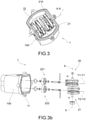
- a cooling system for a vehicle is indicated at 900.
- a water pump for a cooling system e.g. comprised in the cooling system 900, is indicated at 500.
- a regulation assembly which is the object of the present invention, in turn suitable to be comprised in the cooling system 900, is indicated at 1.
- such regulation assembly 1 is, in some preferred embodiments, comprised in the pump group 500; in other words, the regulation assembly 1 is suitable to be an integral part of the pump group 500.
- the regulation assembly 1, object of the present invention is adapted to be part of a vehicle cooling system 900, being positioned downstream of said pump group 500. As described in the embodiment below, the regulation assembly 1 is comprised in the pump group 500, and is positioned downstream of its impeller.
- the regulation assembly 1 is suitable to receive inbound cooling liquid in motion by the action of the pump group 500 and to regulate a predetermined quantity of cooling liquid toward a respective duct of the cooling system 900.
- the regulation assembly 1 comprises at least one inlet port 11 through which the inbound cooling liquid flows from the pump group 500 and at least two outlet ports 121, 122, 123 through which the outbound cooling liquid flows.
- the regulation assembly 1 is fluidically connectable, inbound, to a pump group 500 and, outbound, to at least two components through at least two outlet ducts comprised in a cooling system 900 of a vehicle.
- the regulation assembly 1 comprises two outlet ports 121, 122 and is thus suitable to regulate the amount of cooling liquid toward a first duct or a second duct of a cooling system.
- the regulation assembly 1 comprises three outlet ports 121, 122, 123 and is thus suitable to regulate the amount of cooling liquid to a first duct or a second duct or a third duct of a cooling system.
- the regulation assembly 1 Located between the at least one inlet port 11 and the outlet ports 121, 122, 123, the regulation assembly 1 comprises a regulation chamber 10 in which the cooling liquid is fluidically intercepted and the regulation is carried out.
- regulation means 20 of the regulation assembly 1 are housed.
- the regulation assembly 1 comprises an assembly body 100 defining said regulation chamber 10 and having said at least one inlet port 11 and at least two outlet ports 121, 122, 123.
- said assembly body 100 is adapted to be sealingly connected to the pump group 500, in particular to its pump body 502, so as to create a fluid link between the two.
- the assembly body 100 comprises two shells 101, 102, mutually connected to each other to delimit the regulation chamber 10; preferably, the at least one inlet port 11 is formed on a shell 101, while the at least two outlet ports 121, 122, 123 are formed on the other shell 102.
- Said regulation means 20 comprise a plurality of shutter elements 221, 222, 223 and a regulation member 21 suitable to regulate the position of said shutter elements to thereby regulate the flow of cooling liquid.
- the regulation means 20 comprise at least two shutter elements 221, 222, 223, each operating with a respective outlet port 121, 122, 123.
- the regulation assembly 1 comprises similar shutter elements 221, 222, 223.
- the regulation assembly includes an outlet port which is always open; i.e. on such outlet port no shutter element operates permitting the cooling liquid to flow unimpeded to a respective duct of the cooling system located downstream thereof.
- the regulation assembly is thus suitable to regulate the amount of cooling liquid through the other outlet ports on which the regulation means, and in particular the shutter elements, operate.
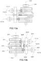
- each shutter element 221, 222, 223 is movable in an axial direction substantially orthogonal to the respective outlet port 121, 122, 123.
- each shutter element 221, 222, 223 is movable axially between a closed position, wherein the respective outlet port on which it operates is occluded (or obstructed or sealed), a plurality of intermediate distal positions from the respective outlet port and an open position corresponding to the maximum opening of the outlet port 121, 122, 123.
- each shutter element 221, 222, 223 is guidable axially from a position wherein it sealingly closes the respective outlet port 121, 122, 123 on which it operates, moving away from it and creating a gap between itself and the outlet port through which the cooling liquid flows.
- each shutter element 221, 222, 223 is movable axially along a respective axis of movement Y1-Y1, Y2-Y2, Y3-Y3.
- each axis of movement Y1-Y1, Y2-Y2, Y3-Y3 is orthogonal to the respective outlet port 121, 122, 123.
- each outlet port 121, 122, 123 there is defined a respective imaginary sectional plane on which the edges that delimit the respective port substantially lie, or median with respect to the position of such edges, and the respective axis of movement Y1-Y1, Y2-Y2, Y3-Y3 is orthogonal to the respective imaginary plane defined.
- each axis of movement Y1-Y1, Y2-Y2, Y3-Y3 is parallel to the flow direction of the cooling liquid through the respective outlet port 121, 122, 123.
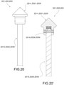
- said axes of movement Y1-Y1, Y2-Y2, Y3-Y3 are parallel to each other.
- said axes of movement Y1-Y1, Y2-Y2, Y3-Y3 are incidental to each other.
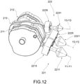
- each shutter element 221, 222, 223 comprises a head element 2211, 2221, 2231 suitable to engage the edges of the respective outlet port 121, 122, 123.
- each head element 2211, 2221, 2231 has a shape substantially complementary to the respective outlet port 121, 122, 123 with which it operates in such a way as to intercept its edges.
- each head element 2211, 2221, 2231 comprises a sealing gasket suitable to operate a sealed obstruction.
- said head element 2211, 2221, 2231 extends axially with a tapered profile, preferably conical or frusto-conical, with circumferential sealing walls suitable to engage the edges of the respective outlet port 121, 122, 123.
- the head element 2211, 2221, 2231 comprises a sealing gasket.
- each shutter element 221, 222, 223 also comprises a control stem 2212, 2222, 2232 extending from the head element 2211, 2221, 2231 to engage the regulation member 21 and then move each in a predetermined axial position from the head element 2211, 2221, 2231.
- each control stem 2212, 2222, 2232 extends orthogonally from the respective head element 2211, 2221, 2231.
- the respective control stem 2212, 2222, 2232 extends along the respective axis of movement Y1-Y1, Y2-Y2, Y3-Y3.
- each shutter element 221, 222, 223 has a substantially “mushroom” shape, with a head and stem extending substantially orthogonally therefrom.
- the engagement between the head element 2211, 2221, 2231 and the control stem 2212, 2222, 2232 is obtained by means of elastic elements 2219, 2229, 2239 suitable to allow a recuperation of play and tolerances between the two.
- a yielding element is housed elastically suitable to perform the role of a compensation element.
- the elastic elements 2219, 2229, 2239 are also suitable to facilitate the engagement of the head element 2211, 2221, 2231 with the edges defining the respective port 121, 122, 123.
- each control stem 2212, 2222, 2232 comprises a control end 2210, 2220, 2230 operatively connected to the regulation member 21.
- each control end 2210, 2220, 2230 is placed on one end of the respective control stem 2212, 2222, 2232, opposite to that of the respective control head 2211, 2221, 2231.
- each control end 2210, 2220, 2230 is positioned in such a way as to lie on the respective axis of movement Y1-Y1, Y2-Y2, Y3-Y3.
- each control end 2210, 2220, 2230 is positioned in such a way as to be transverse, preferably orthogonal, to the respective axis of movement Y1-Y1, Y2-Y2, Y3-Y3.
- each shutter element 221, 222, 223 comprises a respective centering body 2215, 2225, 2235 suitable to maintain the predefined axial position relative to the respective outlet ports 121, 122, 123.
- each centering body 2215, 2225, 2235 keeps the respective shutter element 221, 222, 223 in position to keep the respective head element 2211, 2221, 2231 centered along the respective axis of movement Y1-Y1, Y2-Y2, Y3-Y3, even in the positions wherein it is moved distally from the respective outlet port 121, 122, 123.
- the centering body 2215, 2225, 2235 is a discoidal element through which the respective control stem 2212, 2222, 2232 is housed and supported axially and in rotation.
- the centering body 2215, 2225, 2235 is held in position by the assembly body 100; preferably, the centering body 2215, 2225, 2235 is in geometric interference with the assembly body 100.
- each centering body 2215, 2225, 2235 has special openings through which the cooling liquid flows.
- the regulation member 21 is operatively connected with the shutter elements 221, 222, 223 to guide them to a predefined position corresponding with a regulation of the amount of cooling liquid to a respective duct of the cooling system.
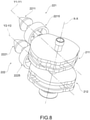
- the regulation member 21 extends along a main axis X-X and is rotatable around said main axis X-X.
- the angular position of the regulation member 21 corresponds to a predefined position of the shutter elements 221, 222, 223 and hence a predefined regulation of the amount of cooling liquid to a respective duct of the cooling system.
- the regulation member 21 is designed to be able to continuously rotate 360° around the main axis X-X.
- a given angular position of the regulation member 21 corresponds to a respective axial position of each shutter element 221, 222, 223.
- the regulation member 21 comprises at least one cont rol passage 210 extending around the main axis X-X defining portions radially distal from the main axis X-X and portions radially proximal to the main axis X-X.
- each control passage 210 is recessed inside the outer walls of the regulation member 21.
- the control member 21 comprises a track or a line or a hollow having some portions radially distal from the main axis X-X and other portions radially proximal to the main axis X-X.
- the shutter element is positioned in a closed position as it interacts with the respective distal portion of the passage, and similarly, the shutter element is positioned in a progression of intermediate positions up to the open position, as a function of the distal portion of the control passage with which it interacts.
- Each shutter element 221, 222, 223, and, in particular, the respective control end 2210, 2220, 2230, is engaged to said control passage 210.
- the respective control end 2210, 2220, 2230 is housed in the control passage 210.
- control ends and control passages are designed to have reciprocal shapes complementary to each other in order to facilitate their reciprocal engagement, while allowing their respective axial and rotational movements.
- control end has a rounded shape, or has a substantially spherical end suitable to be housed in the respective control passage.
- control end has a hinged transverse pin at the end of the control stem and is suitable to be housed in the respective control passage.
- control member 21 comprises a respective control passage 211, 212, 213.
- control passages 211, 212, 213 are respectively axially spaced apart from each other.
- each control end 2210, 2220, 2230 according to the respective preferred embodiment is engaged, housed, in a respective control passage 211, 212, 213.
- the regulation member 21 is arranged within the regulation chamber 10 in such a manner as to have the main axis X-X arranged in a direction substantially orthogonal to the axis of movement Y1-Y1, Y2-Y2, Y3-Y3.
- control member 21 is arranged in a substantially frontal position at the outlet ports 121, 122, 123.
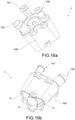
- control member 21 has a substantially cylindrical shape with respect to the main axis X-X (for example, such embodiment is shown in the embodiments of figures 2 to 14 ) .
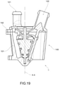
- the regulation member 21 is arranged within the regulation chamber 10 in such a way as to have the main axis X-X arranged in a direction substantially parallel to the axes of movement Y1-Y1, Y2-Y2, Y3-Y3.
- the regulation member 21 is arranged within the regulation chamber 10 in such a way as to have the main axis X-X arranged in a direction with respect to the axes of movement Y1-Y1, Y2-Y2, Y3-Y3 so that said axes converge thereon.
- control member 21 is located in a region defined by the axes of movement Y1-Y1, Y2-Y2, Y3-Y3.
- control member 21 has a substantially conical shape with respect to the main axis.
- the regulation assembly 1 also comprises an electric motor device 50 operatively connected with the regulation member 21 for controlling its rotation around the main axis X-X and placing it in a predefined angular position.
- the electric motor device 50 is mountable on the assembly body 100.
- the regulation member 21 has a member end 215 extending externally from the assembly body 100 on which the electric motor device 50 is engageable to guide the regulation member 21 in rotation.
- the object of the present invention is a pump group 500 for a cooling system 900 of a vehicle comprising a pump body 502, an impeller 505 suitable to draw in cooling fluid through a suction section and to deliver said cooling liquid under pressure in a delivery duct 506 comprised in the pump body 2, preferably by extension of the circuit within which the impeller 505 operates.
- the pump group 500 also comprises a regulation assembly 1 as previously described, fluidically connected to said delivery duct 506 through its inlet port 11.
- object of the present invention is a cooling system 900 of a vehicle comprising a pump group 500 and a regulation assembly 1 according to the foregoing description.
- Said cooling system 900 comprises an engine cooling duct in which the cooling liquid flows through a first outlet port 121 and at least one secondary duct in which the cooling liquid flows passing through at least one second outlet port 122, 123.
- the engine cooling duct in which the cooling liquid flows after its passage from the first outlet port 121 extends into a first main portion of the engine, while the at least one secondary duct, into which the cooling liquid flows after its passage into at least one second outlet port 122, 123, extends into other secondary portions of the engine.
- the regulation assembly object of the present invention fully satisfies the predefined object, i.e. to provide a regulation assembly wherein it is possible to regulate in a customized way, i.e. according to the requirements and as the conditions of use of the vehicle vary, the cooling mode of the engine or a portion of it or other components of the vehicle served by the cooling system, without having any drawbacks due to the cooling of one component rather than another.
- the pump group which comprises the regulation assembly and the cooling system which comprises such regulation assembly are also suitable to fully satisfy such needs and requirements.
- the regulation assembly is suitable to perform the regulation operations in an optimal way, regardless of the modes of opening or closing one duct rather than another.
- the regulation assembly allows for a simple and discreet regulation of the amount of cooling liquid passing through a predefined duct of a cooling system.
- the regulation assembly is suitable to define for each shutter element a precise axial position to which a predetermined amount of cooling liquid corresponds.
- the regulation means are configurable by means of an electric motor in the proper precise regulation configurations.
- the shutter elements are mechanically adjustable to move axially in a plurality of precise, discreet positions.
- the regulation assembly is continuously adjustable while the vehicle is in motion, providing constant regulations of the respective shutter elements during the use of the vehicle, and while being subjected to different ambient conditions, such as a climb or a descent.
- the shutter element is adjustable in a desired axial (intermediate) position.
- a further advantage lies in the fact that the shutter elements are substantially moved in the direction of motion of the flow and consequently are suitable not to generate excessive load losses, such as solutions wherein the shutters are moved orthogonally in the direction of the fluid's motion.
- the described invention is integrable on a plurality of variants of embodiment for the purpose of regulating and controlling the passage of cooling liquid in a plurality of outlet ducts.
- the adjustment assembly is compact in size and therefore particularly suitable to be integrated in the automotive sector, as it is located in the engine compartment of a vehicle.
- the regulation assembly and in particular the regulation means, are designed and arranged in the regulation chamber to minimize the load losses of the cooling liquid.
- the regulation means are adapted to facilitate as far as possible the flow of the cooling liquid; in other words, advantageously, the various components housed in the regulation chamber have fluid-dynamically optimized shapes in order to minimize load losses.
- the regulation assembly is integrable into the pump group itself by providing its positioning in the delivery duct.
Landscapes
- Engineering & Computer Science (AREA)
- General Engineering & Computer Science (AREA)
- Mechanical Engineering (AREA)
- Chemical & Material Sciences (AREA)
- Combustion & Propulsion (AREA)
- Structures Of Non-Positive Displacement Pumps (AREA)
Claims (16)
- Regulierungsanordnung (1) einer Wasserpumpengruppe (500) für ein Kühlungssystem (900) eines Fahrzeugs, beispielsweise seines Motors, welche stromabwärts der Pumpengruppe (500) positionierbar ist, wobei die Regulierungsanordnung (1) umfasst:- wenigstens eine Einlassöffnung (11), durch welche die Kühlungsflüssigkeit von der Pumpengruppe (500) einströmt;- wenigstens zwei Auslassöffnungen (121, 122, 123), durch welche die ausgehende Kühlungsflüssigkeit strömt;- eine Regulierungskammer (10), welche zwischen der Einlassöffnung (11) und den Auslassöffnungen (121, 122, 123) positioniert ist;- ein Regulierungsmittel (20), welches in der Regulierungskammer (10) aufgenommen ist, umfassend:wobei die Regulierungsanordnung (1) durch die Tatsache gekennzeichnet ist, dass das Regulierungselement (21) wenigstens einen Steuerungsdurchgang (210) umfasst, welcher sich um die Hauptachse (X-X) erstreckt, wobei von der Hauptachse (X-X) radial distale Abschnitte und zu der Hauptachse (X-X) radial proximale Abschnitte definiert sind, wobei jedes Verschlusselement (221, 222, 223) ein Steuerungsende (2210, 2220, 2230) umfasst, welches mit dem Steuerungsdurchgang (210) in Eingriff steht.i) wenigstens zwei Verschlusselemente (221, 222, 223), welche mit der jeweiligen Auslassöffnung (121, 122, 123) wirken, wobei jedes Verschlusselement (221, 222, 223) in einer axialen Richtung im Wesentlichen orthogonal zu der jeweiligen Auslassöffnung (121, 122, 123) zwischen einer geschlossenen Position, in welcher die Auslassöffnung verdeckt ist, einer Mehrzahl von der Auslassöffnung distaler Zwischenpositionen und einer offenen Position bewegbar ist, welche der maximalen Öffnung der Auslassöffnung (121, 122, 123) entspricht;ii) ein Regulierungselement (21), welches betriebsmäßig mit den Verschlusselementen (221, 222, 223) verbunden ist und welches sich entlang einer Hauptachse (X-X) erstreckt und um die Hauptachse (X-X) rotierbar ist, derart, dass eine seiner jeweiligen Winkelpositionen einer vordefinierten Position der Verschlusselemente (221, 222, 223) und damit einer Regulierung der Menge von Kühlungsflüssigkeit in Richtung einer jeweiligen Leitung des Kühlungssystems entspricht;
- Regulierungsanordnung (1) nach Anspruch 1, wobei das Regulierungselement (21) für jedes Verschlusselement (221, 222, 223) axial beabstandet jeweilige Steuerungsdurchgänge (211, 212, 213) umfasst, welche durch ein jeweiliges Steuerungsende (2210, 2220, 2230) in Eingriff genommen ist.
- Regulierungsanordnung (1) nach Anspruch 2, wobei jeder Steuerungsdurchgang (210) innerhalb der Außenwände des Regulierungselements (21) vertieft ist.
- Regulierungsanordnung (1) nach einem der vorhergehenden Ansprüche, wobei jedes Verschlusselement (221, 222, 223) entlang einer jeweiligen Bewegungsachse (Y1-Y1, Y2-Y2, Y3-Y3) axial bewegbar ist, wobei die Hauptachse (X-X) eine zu den Bewegungsachsen (Y1-Y1, Y2-Y2, Y3-Y3) im Wesentlichen orthogonale Richtung aufweist.
- Regulierungsanordnung (1) nach Anspruch 4, wobei das Steuerungselement (21) in einer zu den Auslassöffnungen (121, 122, 123) im Wesentlichen frontalen Position angeordnet ist.
- Regulierungsanordnung (1) nach einem der Ansprüche 4 oder 5, wobei das Steuerungselement (21) eine in Bezug auf die Hauptachse (X-X) im Wesentlichen zylindrische Form aufweist.
- Regulierungsanordnung (1) nach einem der Ansprüche 1 bis 3, wobei jedes Verschlusselement (221, 222, 223) entlang einer jeweiligen Bewegungsachse (Y1-Y1, Y2-Y2, Y3-Y3) axial bewegbar ist, wobei die Hauptachse (X-X) eine zu den Bewegungsachsen (Y1-Y1, Y2-Y2, Y3-Y3) im Wesentlichen parallele Richtung aufweist oder die Hauptachse (X-X) eine derartige Richtung aufweist, dass die Bewegungsachsen (Y1-Y1, Y2-Y2, Y3-Y3) an dieser konvergieren.
- Regulierungsanordnung (1) nach Anspruch 7, wobei das Steuerungselement (21) in einem Bereich angeordnet ist, welcher durch die Bewegungsachsen (Y1-Y1, Y2-Y2, Y3-Y3) definiert ist.
- Regulierungsanordnung (1) nach einem der Ansprüche 7 oder 8, wobei das Steuerungselement (21) eine in Bezug auf die Hauptachse im Wesentlichen konische Form aufweist.
- Regulierungsanordnung (1) nach einem der vorhergehenden Ansprüche, wobei jedes Verschlusselement (221, 222, 223) ein Kopfelement (2211, 2221, 2231), welches dazu geeignet ist, mit den Rändern der jeweiligen Auslassöffnung (121, 122, 123) einzugreifen, und einen Steuerschaft (2212, 2222, 2232) umfasst, welcher sich von dem Kopfelement (2211, 2221, 2231) erstreckt, um mit dem Regulierungselement (21) einzugreifen, welches das Steuerungsende (2210, 2220, 2230) umfasst.
- Regulierungsanordnung (1) nach Anspruch 10, wobei sich das Kopfelement (221, 222, 223) axial mit einem verjüngten, vorzugsweise konischen oder kegelstumpfförmigen, Profil erstreckt, wobei es in Umfangsrichtung Dichtungswände aufweist, welche dazu geeignet sind, mit den Rändern der jeweiligen Auslassöffnung (121, 122, 123) einzugreifen.
- Regulierungsanordnung (1) nach einem der vorhergehenden Ansprüche, wobei jedes Steuerungsende (2210, 2220, 2230) in dem Steuerungsdurchgang (210) aufgenommen ist.
- Regulierungsanordnung (1) nach einem der vorhergehenden Ansprüche, wobei jedes Verschlusselement (221, 222, 223) einen Zentrierkörper (2215, 2225, 2235) umfasst, welcher dazu geeignet ist, die vordefinierte axiale Position relativ zu den Auslassöffnungen (121, 122, 123) aufrechtzuerhalten.
- Regulierungsanordnung (1) nach einem der vorhergehenden Ansprüche, umfassend eine elektrische Motorvorrichtung (50), welche betriebsmäßig mit dem Regulierungselement (21) verbunden ist, um seine Rotation um die Hauptachse (X-X) zu steuern und es in einer vordefinierten Winkelposition zu platzieren.
- Pumpengruppe (500) für ein Kühlungssystem (900) eines Fahrzeugs, umfassend:- einen Pumpenkörper (502);- einen Impeller (505), welcher dazu geeignet ist, Kühlungsflüssigkeit durch einen Ansaugabschnitt anzusaugen und die Kühlungsflüssigkeit unter Druck zu einer Zuführleitung (506) zu senden, welche in dem Pumpenkörper (2) umfasst ist;- eine Regulierungsanordnung (1) gemäß einem der vorhergehenden Ansprüche, welche durch ihre Einlassöffnungen (11) fluidisch mit der Zuführleitung (506) verbunden ist.
- Kühlungssystem (900) eines Fahrzeugs, umfassend eine Pumpengruppe (500) und eine Regulierungsanordnung (1) gemäß einem der vorhergehenden Ansprüche, wobei das Kühlungssystem (900) eine Motorkühlleitung, in welcher die Kühlungsflüssigkeit durch eine erste Auslassöffnung (121) strömt, und wenigstens eine sekundäre Leitung umfasst, in welcher die Kühlungsflüssigkeit durch wenigstens eine zweite Auslassöffnung (122, 123) strömt.
Applications Claiming Priority (2)
| Application Number | Priority Date | Filing Date | Title |
|---|---|---|---|
| IT102016000104206A IT201600104206A1 (it) | 2016-10-18 | 2016-10-18 | Assieme di regolazione di un gruppo pompa acqua per un impianto di raffreddamento di un veicolo |
| PCT/IB2017/056314 WO2018073704A1 (en) | 2016-10-18 | 2017-10-12 | A regulation assembly of a water pump group for a cooling system of a vehicle |
Publications (2)
| Publication Number | Publication Date |
|---|---|
| EP3529495A1 EP3529495A1 (de) | 2019-08-28 |
| EP3529495B1 true EP3529495B1 (de) | 2022-03-23 |
Family
ID=58159375
Family Applications (1)
| Application Number | Title | Priority Date | Filing Date |
|---|---|---|---|
| EP17798316.0A Not-in-force EP3529495B1 (de) | 2016-10-18 | 2017-10-12 | Ein regulationsmechanismus einer wasserpumpe für ein kühlsystem des fahrzeugmotors |
Country Status (3)
| Country | Link |
|---|---|
| EP (1) | EP3529495B1 (de) |
| IT (1) | IT201600104206A1 (de) |
| WO (1) | WO2018073704A1 (de) |
Cited By (1)
| Publication number | Priority date | Publication date | Assignee | Title |
|---|---|---|---|---|
| EP4555222A4 (de) * | 2022-08-24 | 2025-10-29 | Cooper Standard Automotive Inc | Mehrport-fluidpumpe mit reservekapazitätslaufrad |
Family Cites Families (3)
| Publication number | Priority date | Publication date | Assignee | Title |
|---|---|---|---|---|
| GB802154A (en) * | 1955-02-02 | 1958-10-01 | Gen Electric | Liquid flow delivery system |
| FR1466329A (fr) * | 1965-09-17 | 1967-01-20 | Chausson Usines Sa | Procédé pour la régulation de la circulation du liquide de refroidissement des moteurs thermiques de véhicules et dispositif pour sa mise en oeuvre |
| US5503118A (en) * | 1995-05-23 | 1996-04-02 | Hollis; Thomas J. | Integral water pump/engine block bypass cooling system |
-
2016
- 2016-10-18 IT IT102016000104206A patent/IT201600104206A1/it unknown
-
2017
- 2017-10-12 WO PCT/IB2017/056314 patent/WO2018073704A1/en not_active Ceased
- 2017-10-12 EP EP17798316.0A patent/EP3529495B1/de not_active Not-in-force
Cited By (1)
| Publication number | Priority date | Publication date | Assignee | Title |
|---|---|---|---|---|
| EP4555222A4 (de) * | 2022-08-24 | 2025-10-29 | Cooper Standard Automotive Inc | Mehrport-fluidpumpe mit reservekapazitätslaufrad |
Also Published As
| Publication number | Publication date |
|---|---|
| EP3529495A1 (de) | 2019-08-28 |
| IT201600104206A1 (it) | 2018-04-18 |
| WO2018073704A1 (en) | 2018-04-26 |
Similar Documents
| Publication | Publication Date | Title |
|---|---|---|
| US20180023459A1 (en) | Exhaust gas turbocharger | |
| EP2880746B1 (de) | Aktive kühlung eines motors | |
| CN107269400A (zh) | 用于调整燃气涡轮发动机中气流畸变的平移入口 | |
| JPH09503567A (ja) | 能動型ベーン付き通路ケーシング処理 | |
| CN107269395A (zh) | 用于调整燃气涡轮发动机中气流畸变的辅助气流通道 | |
| DE102014203498A1 (de) | Verstellbare Düseneinheit und Turbolader mit verstellbarer Geometrie | |
| US20160186623A1 (en) | Variable displacement vane pump with integrated fail safe function | |
| JP2016173051A (ja) | 遠心圧縮機のインペラトリム比可変機構 | |
| CN112400051B (zh) | 一种飞机涡轮机和控制该涡轮机可变旁通阀运动的方法 | |
| US11458806B2 (en) | HVAC inlet with ram air and partial recirculation function | |
| US9316146B2 (en) | Supercharger air flow diverter | |
| EP3529495B1 (de) | Ein regulationsmechanismus einer wasserpumpe für ein kühlsystem des fahrzeugmotors | |
| JP7001438B2 (ja) | 圧縮機 | |
| US20130011250A1 (en) | Mechanical coolant pump | |
| HU220017B (hu) | Szabályozható golyóscsap | |
| EP2815092A1 (de) | Mechanische kühlmittelpumpe | |
| WO2016046682A1 (en) | Valve group with axially movable shutter | |
| EP3990751B1 (de) | Turbine | |
| US11186140B2 (en) | Air intake device for an air conditioning unit of a vehicle | |
| RU2706100C2 (ru) | Перепускное устройство (варианты) и система двигателя | |
| EP3368772B1 (de) | Herausziehbare ventilgruppe mit obturatorgruppe mit mehreren aktiven teilen | |
| US12013192B2 (en) | Valve device having outer circumferential surface having communication hole and groove | |
| JP6059236B2 (ja) | エンジン、例えば自動車エンジンの排気ガス循環バルブ | |
| US20140003913A1 (en) | Infinitely adjustable coolant pump | |
| US11608990B2 (en) | Cooking device |
Legal Events
| Date | Code | Title | Description |
|---|---|---|---|
| STAA | Information on the status of an ep patent application or granted ep patent |
Free format text: STATUS: UNKNOWN |
|
| STAA | Information on the status of an ep patent application or granted ep patent |
Free format text: STATUS: THE INTERNATIONAL PUBLICATION HAS BEEN MADE |
|
| PUAI | Public reference made under article 153(3) epc to a published international application that has entered the european phase |
Free format text: ORIGINAL CODE: 0009012 |
|
| STAA | Information on the status of an ep patent application or granted ep patent |
Free format text: STATUS: REQUEST FOR EXAMINATION WAS MADE |
|
| 17P | Request for examination filed |
Effective date: 20190318 |
|
| AK | Designated contracting states |
Kind code of ref document: A1 Designated state(s): AL AT BE BG CH CY CZ DE DK EE ES FI FR GB GR HR HU IE IS IT LI LT LU LV MC MK MT NL NO PL PT RO RS SE SI SK SM TR |
|
| AX | Request for extension of the european patent |
Extension state: BA ME |
|
| DAV | Request for validation of the european patent (deleted) | ||
| DAX | Request for extension of the european patent (deleted) | ||
| GRAP | Despatch of communication of intention to grant a patent |
Free format text: ORIGINAL CODE: EPIDOSNIGR1 |
|
| STAA | Information on the status of an ep patent application or granted ep patent |
Free format text: STATUS: GRANT OF PATENT IS INTENDED |
|
| INTG | Intention to grant announced |
Effective date: 20211022 |
|
| GRAS | Grant fee paid |
Free format text: ORIGINAL CODE: EPIDOSNIGR3 |
|
| GRAA | (expected) grant |
Free format text: ORIGINAL CODE: 0009210 |
|
| STAA | Information on the status of an ep patent application or granted ep patent |
Free format text: STATUS: THE PATENT HAS BEEN GRANTED |
|
| AK | Designated contracting states |
Kind code of ref document: B1 Designated state(s): AL AT BE BG CH CY CZ DE DK EE ES FI FR GB GR HR HU IE IS IT LI LT LU LV MC MK MT NL NO PL PT RO RS SE SI SK SM TR |
|
| REG | Reference to a national code |
Ref country code: GB Ref legal event code: FG4D |
|
| REG | Reference to a national code |
Ref country code: CH Ref legal event code: EP |
|
| REG | Reference to a national code |
Ref country code: DE Ref legal event code: R096 Ref document number: 602017054978 Country of ref document: DE |
|
| REG | Reference to a national code |
Ref country code: IE Ref legal event code: FG4D |
|
| REG | Reference to a national code |
Ref country code: AT Ref legal event code: REF Ref document number: 1477610 Country of ref document: AT Kind code of ref document: T Effective date: 20220415 |
|
| REG | Reference to a national code |
Ref country code: LT Ref legal event code: MG9D |
|
| REG | Reference to a national code |
Ref country code: NL Ref legal event code: MP Effective date: 20220323 |
|
| PG25 | Lapsed in a contracting state [announced via postgrant information from national office to epo] |
Ref country code: SE Free format text: LAPSE BECAUSE OF FAILURE TO SUBMIT A TRANSLATION OF THE DESCRIPTION OR TO PAY THE FEE WITHIN THE PRESCRIBED TIME-LIMIT Effective date: 20220323 Ref country code: RS Free format text: LAPSE BECAUSE OF FAILURE TO SUBMIT A TRANSLATION OF THE DESCRIPTION OR TO PAY THE FEE WITHIN THE PRESCRIBED TIME-LIMIT Effective date: 20220323 Ref country code: NO Free format text: LAPSE BECAUSE OF FAILURE TO SUBMIT A TRANSLATION OF THE DESCRIPTION OR TO PAY THE FEE WITHIN THE PRESCRIBED TIME-LIMIT Effective date: 20220623 Ref country code: LT Free format text: LAPSE BECAUSE OF FAILURE TO SUBMIT A TRANSLATION OF THE DESCRIPTION OR TO PAY THE FEE WITHIN THE PRESCRIBED TIME-LIMIT Effective date: 20220323 Ref country code: HR Free format text: LAPSE BECAUSE OF FAILURE TO SUBMIT A TRANSLATION OF THE DESCRIPTION OR TO PAY THE FEE WITHIN THE PRESCRIBED TIME-LIMIT Effective date: 20220323 Ref country code: BG Free format text: LAPSE BECAUSE OF FAILURE TO SUBMIT A TRANSLATION OF THE DESCRIPTION OR TO PAY THE FEE WITHIN THE PRESCRIBED TIME-LIMIT Effective date: 20220623 |
|
| REG | Reference to a national code |
Ref country code: AT Ref legal event code: MK05 Ref document number: 1477610 Country of ref document: AT Kind code of ref document: T Effective date: 20220323 |
|
| PG25 | Lapsed in a contracting state [announced via postgrant information from national office to epo] |
Ref country code: LV Free format text: LAPSE BECAUSE OF FAILURE TO SUBMIT A TRANSLATION OF THE DESCRIPTION OR TO PAY THE FEE WITHIN THE PRESCRIBED TIME-LIMIT Effective date: 20220323 Ref country code: GR Free format text: LAPSE BECAUSE OF FAILURE TO SUBMIT A TRANSLATION OF THE DESCRIPTION OR TO PAY THE FEE WITHIN THE PRESCRIBED TIME-LIMIT Effective date: 20220624 Ref country code: FI Free format text: LAPSE BECAUSE OF FAILURE TO SUBMIT A TRANSLATION OF THE DESCRIPTION OR TO PAY THE FEE WITHIN THE PRESCRIBED TIME-LIMIT Effective date: 20220323 |
|
| PG25 | Lapsed in a contracting state [announced via postgrant information from national office to epo] |
Ref country code: NL Free format text: LAPSE BECAUSE OF FAILURE TO SUBMIT A TRANSLATION OF THE DESCRIPTION OR TO PAY THE FEE WITHIN THE PRESCRIBED TIME-LIMIT Effective date: 20220323 |
|
| PG25 | Lapsed in a contracting state [announced via postgrant information from national office to epo] |
Ref country code: SM Free format text: LAPSE BECAUSE OF FAILURE TO SUBMIT A TRANSLATION OF THE DESCRIPTION OR TO PAY THE FEE WITHIN THE PRESCRIBED TIME-LIMIT Effective date: 20220323 Ref country code: SK Free format text: LAPSE BECAUSE OF FAILURE TO SUBMIT A TRANSLATION OF THE DESCRIPTION OR TO PAY THE FEE WITHIN THE PRESCRIBED TIME-LIMIT Effective date: 20220323 Ref country code: RO Free format text: LAPSE BECAUSE OF FAILURE TO SUBMIT A TRANSLATION OF THE DESCRIPTION OR TO PAY THE FEE WITHIN THE PRESCRIBED TIME-LIMIT Effective date: 20220323 Ref country code: PT Free format text: LAPSE BECAUSE OF FAILURE TO SUBMIT A TRANSLATION OF THE DESCRIPTION OR TO PAY THE FEE WITHIN THE PRESCRIBED TIME-LIMIT Effective date: 20220725 Ref country code: ES Free format text: LAPSE BECAUSE OF FAILURE TO SUBMIT A TRANSLATION OF THE DESCRIPTION OR TO PAY THE FEE WITHIN THE PRESCRIBED TIME-LIMIT Effective date: 20220323 Ref country code: EE Free format text: LAPSE BECAUSE OF FAILURE TO SUBMIT A TRANSLATION OF THE DESCRIPTION OR TO PAY THE FEE WITHIN THE PRESCRIBED TIME-LIMIT Effective date: 20220323 Ref country code: CZ Free format text: LAPSE BECAUSE OF FAILURE TO SUBMIT A TRANSLATION OF THE DESCRIPTION OR TO PAY THE FEE WITHIN THE PRESCRIBED TIME-LIMIT Effective date: 20220323 Ref country code: AT Free format text: LAPSE BECAUSE OF FAILURE TO SUBMIT A TRANSLATION OF THE DESCRIPTION OR TO PAY THE FEE WITHIN THE PRESCRIBED TIME-LIMIT Effective date: 20220323 |
|
| PG25 | Lapsed in a contracting state [announced via postgrant information from national office to epo] |
Ref country code: PL Free format text: LAPSE BECAUSE OF FAILURE TO SUBMIT A TRANSLATION OF THE DESCRIPTION OR TO PAY THE FEE WITHIN THE PRESCRIBED TIME-LIMIT Effective date: 20220323 Ref country code: IS Free format text: LAPSE BECAUSE OF FAILURE TO SUBMIT A TRANSLATION OF THE DESCRIPTION OR TO PAY THE FEE WITHIN THE PRESCRIBED TIME-LIMIT Effective date: 20220723 Ref country code: AL Free format text: LAPSE BECAUSE OF FAILURE TO SUBMIT A TRANSLATION OF THE DESCRIPTION OR TO PAY THE FEE WITHIN THE PRESCRIBED TIME-LIMIT Effective date: 20220323 |
|
| REG | Reference to a national code |
Ref country code: DE Ref legal event code: R097 Ref document number: 602017054978 Country of ref document: DE |
|
| PLBE | No opposition filed within time limit |
Free format text: ORIGINAL CODE: 0009261 |
|
| STAA | Information on the status of an ep patent application or granted ep patent |
Free format text: STATUS: NO OPPOSITION FILED WITHIN TIME LIMIT |
|
| PG25 | Lapsed in a contracting state [announced via postgrant information from national office to epo] |
Ref country code: DK Free format text: LAPSE BECAUSE OF FAILURE TO SUBMIT A TRANSLATION OF THE DESCRIPTION OR TO PAY THE FEE WITHIN THE PRESCRIBED TIME-LIMIT Effective date: 20220323 |
|
| 26N | No opposition filed |
Effective date: 20230102 |
|
| PG25 | Lapsed in a contracting state [announced via postgrant information from national office to epo] |
Ref country code: SI Free format text: LAPSE BECAUSE OF FAILURE TO SUBMIT A TRANSLATION OF THE DESCRIPTION OR TO PAY THE FEE WITHIN THE PRESCRIBED TIME-LIMIT Effective date: 20220323 Ref country code: MC Free format text: LAPSE BECAUSE OF FAILURE TO SUBMIT A TRANSLATION OF THE DESCRIPTION OR TO PAY THE FEE WITHIN THE PRESCRIBED TIME-LIMIT Effective date: 20220323 |
|
| REG | Reference to a national code |
Ref country code: CH Ref legal event code: PL |
|
| REG | Reference to a national code |
Ref country code: BE Ref legal event code: MM Effective date: 20221031 |
|
| GBPC | Gb: european patent ceased through non-payment of renewal fee |
Effective date: 20221012 |
|
| P01 | Opt-out of the competence of the unified patent court (upc) registered |
Effective date: 20230523 |
|
| PG25 | Lapsed in a contracting state [announced via postgrant information from national office to epo] |
Ref country code: LU Free format text: LAPSE BECAUSE OF NON-PAYMENT OF DUE FEES Effective date: 20221012 |
|
| PG25 | Lapsed in a contracting state [announced via postgrant information from national office to epo] |
Ref country code: LI Free format text: LAPSE BECAUSE OF NON-PAYMENT OF DUE FEES Effective date: 20221031 Ref country code: FR Free format text: LAPSE BECAUSE OF NON-PAYMENT OF DUE FEES Effective date: 20221031 Ref country code: CH Free format text: LAPSE BECAUSE OF NON-PAYMENT OF DUE FEES Effective date: 20221031 |
|
| PG25 | Lapsed in a contracting state [announced via postgrant information from national office to epo] |
Ref country code: BE Free format text: LAPSE BECAUSE OF NON-PAYMENT OF DUE FEES Effective date: 20221031 |
|
| PG25 | Lapsed in a contracting state [announced via postgrant information from national office to epo] |
Ref country code: IE Free format text: LAPSE BECAUSE OF NON-PAYMENT OF DUE FEES Effective date: 20221012 Ref country code: GB Free format text: LAPSE BECAUSE OF NON-PAYMENT OF DUE FEES Effective date: 20221012 |
|
| PGFP | Annual fee paid to national office [announced via postgrant information from national office to epo] |
Ref country code: IT Payment date: 20230807 Year of fee payment: 7 |
|
| PGFP | Annual fee paid to national office [announced via postgrant information from national office to epo] |
Ref country code: DE Payment date: 20231020 Year of fee payment: 7 |
|
| PG25 | Lapsed in a contracting state [announced via postgrant information from national office to epo] |
Ref country code: HU Free format text: LAPSE BECAUSE OF FAILURE TO SUBMIT A TRANSLATION OF THE DESCRIPTION OR TO PAY THE FEE WITHIN THE PRESCRIBED TIME-LIMIT; INVALID AB INITIO Effective date: 20171012 |
|
| PG25 | Lapsed in a contracting state [announced via postgrant information from national office to epo] |
Ref country code: CY Free format text: LAPSE BECAUSE OF FAILURE TO SUBMIT A TRANSLATION OF THE DESCRIPTION OR TO PAY THE FEE WITHIN THE PRESCRIBED TIME-LIMIT Effective date: 20220323 |
|
| PG25 | Lapsed in a contracting state [announced via postgrant information from national office to epo] |
Ref country code: MK Free format text: LAPSE BECAUSE OF FAILURE TO SUBMIT A TRANSLATION OF THE DESCRIPTION OR TO PAY THE FEE WITHIN THE PRESCRIBED TIME-LIMIT Effective date: 20220323 |
|
| PG25 | Lapsed in a contracting state [announced via postgrant information from national office to epo] |
Ref country code: TR Free format text: LAPSE BECAUSE OF FAILURE TO SUBMIT A TRANSLATION OF THE DESCRIPTION OR TO PAY THE FEE WITHIN THE PRESCRIBED TIME-LIMIT Effective date: 20220323 |
|
| PG25 | Lapsed in a contracting state [announced via postgrant information from national office to epo] |
Ref country code: MT Free format text: LAPSE BECAUSE OF FAILURE TO SUBMIT A TRANSLATION OF THE DESCRIPTION OR TO PAY THE FEE WITHIN THE PRESCRIBED TIME-LIMIT Effective date: 20220323 |
|
| REG | Reference to a national code |
Ref country code: DE Ref legal event code: R119 Ref document number: 602017054978 Country of ref document: DE |
|
| PG25 | Lapsed in a contracting state [announced via postgrant information from national office to epo] |
Ref country code: DE Free format text: LAPSE BECAUSE OF NON-PAYMENT OF DUE FEES Effective date: 20250501 |
|
| PG25 | Lapsed in a contracting state [announced via postgrant information from national office to epo] |
Ref country code: IT Free format text: LAPSE BECAUSE OF NON-PAYMENT OF DUE FEES Effective date: 20241012 |