EP3636423A1 - Procédé de fabrication d'un élément optique avec un film fonctionnel - Google Patents
Procédé de fabrication d'un élément optique avec un film fonctionnel Download PDFInfo
- Publication number
- EP3636423A1 EP3636423A1 EP18306330.4A EP18306330A EP3636423A1 EP 3636423 A1 EP3636423 A1 EP 3636423A1 EP 18306330 A EP18306330 A EP 18306330A EP 3636423 A1 EP3636423 A1 EP 3636423A1
- Authority
- EP
- European Patent Office
- Prior art keywords
- film
- optical lens
- assembly
- cutting element
- cutting
- Prior art date
- Legal status (The legal status is an assumption and is not a legal conclusion. Google has not performed a legal analysis and makes no representation as to the accuracy of the status listed.)
- Withdrawn
Links
Images


Classifications
-
- B—PERFORMING OPERATIONS; TRANSPORTING
- B29—WORKING OF PLASTICS; WORKING OF SUBSTANCES IN A PLASTIC STATE IN GENERAL
- B29D—PRODUCING PARTICULAR ARTICLES FROM PLASTICS OR FROM SUBSTANCES IN A PLASTIC STATE
- B29D11/00—Producing optical elements, e.g. lenses or prisms
- B29D11/00009—Production of simple or compound lenses
- B29D11/00317—Production of lenses with markings or patterns
-
- B—PERFORMING OPERATIONS; TRANSPORTING
- B29—WORKING OF PLASTICS; WORKING OF SUBSTANCES IN A PLASTIC STATE IN GENERAL
- B29D—PRODUCING PARTICULAR ARTICLES FROM PLASTICS OR FROM SUBSTANCES IN A PLASTIC STATE
- B29D11/00—Producing optical elements, e.g. lenses or prisms
- B29D11/0073—Optical laminates
-
- B—PERFORMING OPERATIONS; TRANSPORTING
- B24—GRINDING; POLISHING
- B24B—MACHINES, DEVICES, OR PROCESSES FOR GRINDING OR POLISHING; DRESSING OR CONDITIONING OF ABRADING SURFACES; FEEDING OF GRINDING, POLISHING, OR LAPPING AGENTS
- B24B13/00—Machines or devices designed for grinding or polishing optical surfaces on lenses or surfaces of similar shape on other work; Accessories therefor
- B24B13/005—Blocking means, chucks or the like; Alignment devices
- B24B13/0057—Deblocking of lenses
-
- B—PERFORMING OPERATIONS; TRANSPORTING
- B29—WORKING OF PLASTICS; WORKING OF SUBSTANCES IN A PLASTIC STATE IN GENERAL
- B29D—PRODUCING PARTICULAR ARTICLES FROM PLASTICS OR FROM SUBSTANCES IN A PLASTIC STATE
- B29D11/00—Producing optical elements, e.g. lenses or prisms
- B29D11/00009—Production of simple or compound lenses
- B29D11/00432—Auxiliary operations, e.g. machines for filling the moulds
-
- B—PERFORMING OPERATIONS; TRANSPORTING
- B29—WORKING OF PLASTICS; WORKING OF SUBSTANCES IN A PLASTIC STATE IN GENERAL
- B29C—SHAPING OR JOINING OF PLASTICS; SHAPING OF MATERIAL IN A PLASTIC STATE, NOT OTHERWISE PROVIDED FOR; AFTER-TREATMENT OF THE SHAPED PRODUCTS, e.g. REPAIRING
- B29C2793/00—Shaping techniques involving a cutting or machining operation
- B29C2793/009—Shaping techniques involving a cutting or machining operation after shaping
-
- B—PERFORMING OPERATIONS; TRANSPORTING
- B29—WORKING OF PLASTICS; WORKING OF SUBSTANCES IN A PLASTIC STATE IN GENERAL
- B29C—SHAPING OR JOINING OF PLASTICS; SHAPING OF MATERIAL IN A PLASTIC STATE, NOT OTHERWISE PROVIDED FOR; AFTER-TREATMENT OF THE SHAPED PRODUCTS, e.g. REPAIRING
- B29C63/00—Lining or sheathing, i.e. applying preformed layers or sheathings of plastics; Apparatus therefor
- B29C63/02—Lining or sheathing, i.e. applying preformed layers or sheathings of plastics; Apparatus therefor using sheet or web-like material
-
- B—PERFORMING OPERATIONS; TRANSPORTING
- B29—WORKING OF PLASTICS; WORKING OF SUBSTANCES IN A PLASTIC STATE IN GENERAL
- B29L—INDEXING SCHEME ASSOCIATED WITH SUBCLASS B29C, RELATING TO PARTICULAR ARTICLES
- B29L2011/00—Optical elements, e.g. lenses, prisms
- B29L2011/0016—Lenses
Definitions
- the invention relates to a method for manufacturing an optical element with a functional film.
- such an optical element is manufactured by a lamination technique consisting in thermoforming a functional film before depositing it under pressure on an optical element surface which is already attached to a blocking piece.
- the functional film may be an anti-reflective coating.
- a method pursuant to the invention allows the optical element with the film to be satisfactory manufactured by eliminating the risk of a film delamination during the step of separating the optical element with the film from the blocking piece.
- the inventors have observed the laminated optical elements before and after the step of separating the optical element with the film from the blocking piece.
- One object of the invention is a method for manufacturing an optical lens and comprising the following steps:
- the originality of a method pursuant to the invention consists in including a step of reducing the film shape prior to the deblocking step, in order to prevent any delamination phenomenon of the film adhering to the optical element.
- the deblocking step is generally achieved by means of a pressurized fluid jet, and if the film protrudes from the lens in some radial directions, said fluid jet may dissociate the functional film from the optical element before the end of the deblocking step.
- the deblocking step will not have any negative influence on the functional film or adhesion layer and its position on the optical element, and the resulting piece comprising the optical element and said film will have the required quality.
- the functional film aims to improve the optical properties of the optical element in particular by providing it with added features such as a hard coat, an anti-reflective coating or a polarizing film, anti-shock properties, a tint, a mirror or a filter for specific wavelength, anti-smudge, anti-fog or antistatic properties, self-healing or self-cleaning properties, etc.
- the optical lens may have a curved profile including a concave surface, a convex surface or may have a planar profile.
- the blocking piece acts as a support for the optical element in order to maintain said optical lens in a fixed position during the laminating step.
- the step of cutting the film may be achieved with any means capable of reducing the film size, for example a laser beam or a blade.
- the film shape reduction may be achieved homogeneously, for example in a symmetric manner, or only in particular directions where some parts of the film extend from the optical lens edge.
- the step of cutting the film excess allows that the entire film surface is completely adhered on the lens surface, without any part of the film which overhangs the edge of the lens and that could create a drag for a pressurized fluid jet during the deblocking step.
- the aim of cutting the film is to maintain the dimensions of the film less or equal to the surface of the optical lens against which said film will be applied.
- the step of cutting the excess film is determined so as to obtain a minimum radial distance in a plan view between the film edge and the laminated lens surface edge which is between 0.05mm and 10mm, preferably between 0.5mm and 5mm, for example between 1mm and 3 mm. Said otherwise, the step of cutting the excess film may be such that the film is cut smaller than the edges of the laminated lens surface. It is important to not reduce too much the film size, because said functional film must be approximately applied on the whole surface of the optical element after a future edging step used to machine the optical element to a contour adapted to fit in a predetermined frame of spectacles.
- the step of cutting the excess film is carried out with one cutting element to be chosen among a sharp edge, a laser cutter, and a blade.
- one cutting element to be chosen among a sharp edge, a laser cutter, and a blade.
- These examples are illustrative and are not limitative.
- These three cutting elements are particularly suitable for cutting a film which has been beforehand deposited on the optical element by a lamination technique.
- the method further comprises the following steps:
- the cutting step may be carried out indifferently with a fixed cutting means and a rotary assembly support, or with a fixed assembly support and moving cutting means. What is very important in the framework of a method pursuant to the invention, is that there is a relative movement between the cutting element and the assembly support, so that this cutting element move around the film at a predetermined distance from the center of the assembly support.
- the functional laminated film comprises a main film made of Cellulose Triacetate (TAC), polyethylene terephthalate (PET), polycarbonate (PC), Polyvinyl Alcohol (PVA), or Cyclic Olefin Copolymer (COC). Films with such compositions can be easily and accurately cut, to have the suitable form and size with respect to the optical lens on which the film is deposited.
- TAC Cellulose Triacetate
- PET polyethylene terephthalate
- PC polycarbonate
- PVA Polyvinyl Alcohol
- COC Cyclic Olefin Copolymer
- the functional laminated film provides at least one feature to the lens to be chosen among a hard coat, an anti-reflective coating or a polarizing film, anti-shock properties, a tint, a mirror or a filter for specific wavelength, anti-smudge, anti-fog or antistatic properties, self-healing or self-cleaning properties, alone or in combination.
- a hard coat an anti-reflective coating or a polarizing film
- anti-shock properties a tint, a mirror or a filter for specific wavelength, anti-smudge, anti-fog or antistatic properties, self-healing or self-cleaning properties, alone or in combination.
- the optical lens with the film is fastened to the blocking piece by means of a bonding material, and wherein the deblocking step is carried out with at least a pressurized fluid jet intended to separate the lens with the film from the bonding material. If some parts of the film extend beyond the optical element and overhang the edges of said optical element, the pressurized fluid jet may separate said film from the optical element, and thus the optical lens is defective and must be replaced.
- Another object of the invention is an apparatus for achieving the cutting step of a method pursuant to the invention.
- the apparatus comprises an assembly support intended for receiving an assembly comprising the optical lens with the functional laminated film and the blocking piece, and a cutting element adapted to cut an excess film present on said assembly and having a surface that spread out of said optical lens, and thus having some parts overhanging over the optical lens.
- This apparatus schematically comprises a support intended to receive an assembly constituted by the optical lens with the laminated film and the blocking piece, and a cutting element adapted to cut an excess film present on this assembly.
- This apparatus can be used manually, or automatically with a motor intended to activate the cutting element and/or to generate a movement of said cutting element relative to the assembly support or the contrary (a movement of the assembly support relative to the cutting element).
- the cutting element is one of a sharp edge, a laser cutter, and a blade. These examples are only illustrative and are not limitative. These three cutting elements are particularly suitable for cutting a film which has been beforehand laminated on the optical element
- the apparatus further comprises an arm equipped with a cutting element, said arm being placed relatively to the assembly support so that the cutting element is placed over the film edge at a predetermined distance from the assembly support center.
- This predetermined position can be calculated or measured. Once the predetermined position is known it becomes easy to position the arm in the suitable position so as to place the cutting element close to the edge of the optical lens, where it is suitable to cut the film.
- the predetermined distance may result from measurements and/or calculations. This predetermined distance leads to position the cutting element at a precise radial distance from the optical lens edge to ensure a clean cut of the film.
- At least one element to be chosen among the assembly support and the arm equipped with the cutting element is adapted to rotate about a central axis of the assembly support.
- the assembly support is cylindrical-shaped and is designed to rotate about its revolution axis which extends in a vertical direction, and the arm extends in a horizontal direction.
- the arm is placed above the film and the cutting element acts in a vertical direction.
- the position of the arm is adjustable to adapt the cutting element position to the film sizes, so that said cutting element is placed above the film edge at a predetermined radial distance from the optical lens edge, and preferably over the surface of the optical lens.
- the position of the arm is adjustable to adapt the cutting element position to the contour of the optical lens, so that said cutting element is placed above the film edge at a predetermined radial distance from the optical lens edge, and preferably over the surface of the optical lens.
- Said position with regard to the center of the optical lens, may thus vary depending on the shape of the lens contour.
- Said position may for example be adjusted by having had a prior reading of the contour of the optical lens edge, or by having the position of the arm be adjusted with regard to the feedback of a sensor positioned so as to acquire a position of the edge of the lens near the position of the cutting element.
- a method pursuant to the invention presents the advantage to be conducted continuously, without any risk of delamination of the film during the deblocking step. Moreover, while it includes a supplemental step consisting in cutting the excess film which overhang the edge of the optical lens, said step is achieved with an apparatus which is easy and rapid to handle and which produces a clean cut of the film.
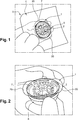
- a lamination method when a lamination method is used to deposit a functional film 1 on an optical element which is generally constituted by an optical lens 2, a final first assembly 3 comprising said optical lens 2 with said film 1, a carrier 4 and a blocking piece 5 is obtained.
- a multilayers assembly comprising the functional film 1, the carrier 4 and different layers placed therebetween, is beforehand thermoformed in order to adapt the form of the functional film 1 to the surface of the optical lens 2 intended to receive said functional film 1.
- this multilayers assembly is laminated on the surface of the optical lens 2, and once said multilayers assembly has been deposited on said optical lens 2, we obtain the first assembly 3 showed in figure 1 .
- the functional laminated film 1 provides at least one feature to the optical lens 2 to be chosen among a hard coat, an anti-reflective coating or a polarizing film, anti-shock properties, a tint, a mirror or a filter for specific wavelength, self-healing or self-cleaning properties, a surface modifier having anti-smudge, anti-fog or antistatic properties, alone or in combination.
- a functional film has a protection function in regard to the optical lens 2 on which it is deposited, or a supplemental optical function intended to improve the optical properties and/or characteristics of the optical lens 2.
- the functions of said functional film 1 are thus non-limited to the examples listed before, which are only illustrative and not limitative.
- the functional laminated film 1 comprises a main film made of Cellulose Triacetate (TAC), polyethylene terephthalate (PET), polycarbonate (PC), Polyvinyl Alcohol (PVA), or Cyclic Olefin Copolymer (COC). These are only illustrative examples which are not limitative in the framework of a method pursuant to the invention.
- TAC Cellulose Triacetate
- PET polyethylene terephthalate
- PC polycarbonate
- PVA Polyvinyl Alcohol
- COC Cyclic Olefin Copolymer
- the blocking piece 5 acts as a receptacle to receive the optical lens 2 just before the film lamination step occurs.
- a blocking piece 5 is designed to maintain the optical lens 2 in a stable manner before the film lamination step is achieved. On that subject the optical lens 2 is fixed in the blocking piece 5 by means of an adhesive material.
- the carrier 4 which is a rigid and transparent plastic film is manually removed from the first assembly 3.
- a second assembly 6 made of the optical lens 2 with the functional laminated film 1 and the blocking piece 5, said second assembly constituting an independent resulting piece which can be easily handled and/or transported to finally obtain the suitable optical lens 2 with a functional film 1 having a homogeneous adherence on said optical lens 2, and having the required size with respect to the lens 2 dimensions.
- the optical lens 2 and the blocking piece 5 have a circular contour and each have a symmetry of revolution.
- the surfacing step happens to reduce the diameter of the optical lens as compared to the initial dimension of the semi-finished lens.
- Such reduction of diameter may lead to the maximum dimension of the film being larger than the surfaced lens diameter, or more precisely having part of the film overhanging above the surface lens edge, when the film is oriented and centered with the optical center of the lens.
- the final diameter after such reduction of diameter during the surfacing step depends on the prescription desired for the optical lens, ie the optical power. Accordingly, a multiplicity of such diameters may be produced. Further such reduction of diameter may lead to lens contour that do not have symmetry of revolution anymore. Accordingly, in such cases, if one desire films that mostly cover most of the surface of the lens, at least in one dimension, but do not have any overhang, the construction of an inventory of films patches of various dimensions becomes highly complicated.
- said separating step is generally achieved by means of pressurized fluid jet and thus, it is possible and even probable, that said pressurized fluid jet generates a film delamination which can lead to a film 2 removal. Consequently, the film lamination step must be restarted, greatly increasing the optical lens manufacturing costs.
- a method of manufacturing an optical lens 2 pursuant to the invention comprises a step of cutting the film 1 excess 20, directly on the second assembly 6 obtained.
- this cutting step is to limit the film size so that the film dimensions be completely included in the optical lens dimensions.
- the film size is to be equal or less than the size of the optical lens 2.
- this cutting step allows obtaining a minimum radial distance d in a plan view between the film 1 edge and the laminated lens surface edge which is comprised between 0.05mm and 10mm, preferably comprised between 0.1mm and 5mm, for example between 0.5mm and 3 mm.
- the cutting step is carried out with an apparatus 10 comprising an arm 11 equipped with a cutting element 12, and an assembly support 13 intended to receive the second assembly 6.
- the cutting element 12 may for example be chosen among a sharp edge, a laser cutter, and a blade. In a general manner, any type of cutting means works, if it is capable of cleanly cutting the functional film 1 with a certain accuracy.
- the arm 11 extends in a horizontal direction and have a first extremity which is linked to a vertical cylindrical rod 14 and a second extremity where the cutting element 12 is placed.
- the arm distance from a center of the assembly support 13 is adjustable so as to adapt the arm position, or dimension, to a specific optical lens 2 size.
- the assembly support 13 is cylindrical-shaped and is positioned on a cylindrical platform 15 of the apparatus 10, so that its axis of revolution extends in a vertical direction perpendicularly to the platform surface 15.
- This assembly support 13 is delimited by a circular bottom and by a cylindrical lateral wall 16 and is rotatably mounted on the platform 15 about its axis of revolution.
- the assembly support 13 may be rotated, either manually, or automatically by means of a motor and a control device. When the assembly support 13 is handled manually by an operator, said operator can adjust the rotation direction in function of his need. In this configuration, it is supposed that the assembly support 13 is freely mounted in rotation in the two possible directions of rotation about its revolution axis. In a same way, when a motor makes rotated the assembly support 13, said motor is designed to allow a rotation movement of the assembly support 13 in the two possible directions of rotation about its revolution axis.
- An electrical motor is particularly suitable to perform such assembly support 13 rotary movements.
- the second assembly 6 is placed inside the assembly support 13 so that the optical lens 2 and the functional film 13 protrude above said assembly support 13, the functional film 1 corresponding to the upper part of said second assembly 6.
- the functional film 1 extend in a plan which is approximately horizontal (the term "approximately” is used because the functional film is not rigorously plan).
- the arm is then positioned with respect to the vertical rod, and its position or length is eventually adjusted so as to lead the cutting element 12 above the functional film 1 at a given radial distance "d" from the peripheral edge of the optical lens 2, inside said optical lens 2.
- the cutting element 12 is then above the lens surface so as to have a radial distance "d" which is directed toward the center of the lens, and having a part of the surface of the optical lens uncovered from the film on the whole contour of the optical lens.
- a sensor/feeler enables to automatically adapt the position of the cutting element 12 to the position of the edge of the optical lens.
- the cutting element 12 is then activated to contact the functional film 1 and to begin the cutting step.
- the assembly support 13 is rotated, manually or automatically with a motor.
- the deblocking step can begin to separate the optical lens 2 with the film 1 and the blocking piece 5 without any risk of film delamination, because the film 1 is completely included in the optical lens 2 without any part which extends beyond the optical lens edge 7.
Landscapes
- Engineering & Computer Science (AREA)
- Manufacturing & Machinery (AREA)
- Mechanical Engineering (AREA)
- Health & Medical Sciences (AREA)
- Ophthalmology & Optometry (AREA)
- Polarising Elements (AREA)
Priority Applications (5)
| Application Number | Priority Date | Filing Date | Title |
|---|---|---|---|
| EP18306330.4A EP3636423A1 (fr) | 2018-10-09 | 2018-10-09 | Procédé de fabrication d'un élément optique avec un film fonctionnel |
| CN201980066628.2A CN112805145A (zh) | 2018-10-09 | 2019-10-09 | 用于制造具有功能膜的光学元件的方法 |
| PCT/EP2019/077407 WO2020074608A1 (fr) | 2018-10-09 | 2019-10-09 | Procédé de fabrication d'un élément optique avec un film fonctionnel |
| US17/283,918 US20210347134A1 (en) | 2018-10-09 | 2019-10-09 | Method for manufacturing an optical element with a functional film |
| EP19780278.8A EP3863842A1 (fr) | 2018-10-09 | 2019-10-09 | Procédé de fabrication d'un élément optique avec un film fonctionnel |
Applications Claiming Priority (1)
| Application Number | Priority Date | Filing Date | Title |
|---|---|---|---|
| EP18306330.4A EP3636423A1 (fr) | 2018-10-09 | 2018-10-09 | Procédé de fabrication d'un élément optique avec un film fonctionnel |
Publications (1)
| Publication Number | Publication Date |
|---|---|
| EP3636423A1 true EP3636423A1 (fr) | 2020-04-15 |
Family
ID=63857850
Family Applications (2)
| Application Number | Title | Priority Date | Filing Date |
|---|---|---|---|
| EP18306330.4A Withdrawn EP3636423A1 (fr) | 2018-10-09 | 2018-10-09 | Procédé de fabrication d'un élément optique avec un film fonctionnel |
| EP19780278.8A Pending EP3863842A1 (fr) | 2018-10-09 | 2019-10-09 | Procédé de fabrication d'un élément optique avec un film fonctionnel |
Family Applications After (1)
| Application Number | Title | Priority Date | Filing Date |
|---|---|---|---|
| EP19780278.8A Pending EP3863842A1 (fr) | 2018-10-09 | 2019-10-09 | Procédé de fabrication d'un élément optique avec un film fonctionnel |
Country Status (4)
| Country | Link |
|---|---|
| US (1) | US20210347134A1 (fr) |
| EP (2) | EP3636423A1 (fr) |
| CN (1) | CN112805145A (fr) |
| WO (1) | WO2020074608A1 (fr) |
Cited By (1)
| Publication number | Priority date | Publication date | Assignee | Title |
|---|---|---|---|---|
| EP4194189A1 (fr) * | 2021-12-13 | 2023-06-14 | Essilor International | Procédé de fabrication d'un élément ophtalmique comprenant une structure de film |
Citations (4)
| Publication number | Priority date | Publication date | Assignee | Title |
|---|---|---|---|---|
| US5451281A (en) * | 1994-01-18 | 1995-09-19 | Lipman; Arnold | Process for imparting scratch resistance to ophthalmic lenses during edging |
| US20100006219A1 (en) * | 2006-08-04 | 2010-01-14 | Essilor International (Compagnie Generale D'optique) | Method of applying a coating on a face of a lens, and apparatus for implementing such a method |
| US20130095733A1 (en) * | 2010-07-13 | 2013-04-18 | Essilor International (Compagnie Generale D'optique) | Method for trimming an ophthalmic eyeglass lens comprising a coating film |
| US20140333891A1 (en) * | 2011-12-07 | 2014-11-13 | Kilworth Business & Properties Ltd | 3d prescription spectacle lens and method of manufacture |
Family Cites Families (10)
| Publication number | Priority date | Publication date | Assignee | Title |
|---|---|---|---|---|
| FR2613275B1 (fr) * | 1987-03-30 | 1989-06-09 | Essilor Int | Procede et appareil pour coller un film protecteur sur une face d'une serie de lentilles ophtalmiques |
| US5474489A (en) * | 1991-03-27 | 1995-12-12 | D.A.C., Inc. | Lens blocking and constant center thickness system |
| US5343657A (en) * | 1992-09-18 | 1994-09-06 | Venture Tape Corporation | Method and apparatus for masking removable optical lens markings during lens grinding |
| EP1079965B1 (fr) * | 1998-04-17 | 2002-09-18 | Barberini S.P.A. | Systeme et procede de collage automatique de lentilles de polarisation |
| JP2005175384A (ja) * | 2003-12-15 | 2005-06-30 | Nitto Denko Corp | 保護テープの貼付方法及び剥離方法 |
| DE102010010334B4 (de) * | 2010-03-04 | 2012-01-19 | Satisloh Ag | Vorrichtung zum Abblocken von optischen Werkstücken, insbesondere Brillengläsern |
| EA024639B1 (ru) * | 2011-05-12 | 2016-10-31 | Эссилор Энтернасьональ (Компани Женераль Д'Оптик) | Оптическое изделие, содержащее покрытие-предшественник для противозапотевающего покрытия и временный слой, придающий противозапотевающие свойства, подходящее для проведения обработки краев |
| DE102012202965B4 (de) * | 2012-02-27 | 2021-01-28 | Carl Zeiss Vision International Gmbh | Trägervorrichtung für das Handhaben einer Linse, Packungssytem mit einer Trägervorrichtung für das Handhaben einer darin aufgenommenen Linse, Verfahren zum Herstellen eines Packungssystems und Verfahren zum Bearbeiten von Linsen |
| EP2963458B1 (fr) * | 2014-07-05 | 2022-02-02 | Satisloh AG | Ébauche de lentille comportant un revêtement de préhension temporaire pour un procédé de verres de lunettes selon une prescription |
| EP3009230B1 (fr) * | 2014-10-15 | 2021-01-13 | Satisloh AG | Unité de blocage pour une pièce de blocage pour un verre de lunettes et procédé de durcissement |
-
2018
- 2018-10-09 EP EP18306330.4A patent/EP3636423A1/fr not_active Withdrawn
-
2019
- 2019-10-09 EP EP19780278.8A patent/EP3863842A1/fr active Pending
- 2019-10-09 US US17/283,918 patent/US20210347134A1/en active Pending
- 2019-10-09 CN CN201980066628.2A patent/CN112805145A/zh active Pending
- 2019-10-09 WO PCT/EP2019/077407 patent/WO2020074608A1/fr unknown
Patent Citations (4)
| Publication number | Priority date | Publication date | Assignee | Title |
|---|---|---|---|---|
| US5451281A (en) * | 1994-01-18 | 1995-09-19 | Lipman; Arnold | Process for imparting scratch resistance to ophthalmic lenses during edging |
| US20100006219A1 (en) * | 2006-08-04 | 2010-01-14 | Essilor International (Compagnie Generale D'optique) | Method of applying a coating on a face of a lens, and apparatus for implementing such a method |
| US20130095733A1 (en) * | 2010-07-13 | 2013-04-18 | Essilor International (Compagnie Generale D'optique) | Method for trimming an ophthalmic eyeglass lens comprising a coating film |
| US20140333891A1 (en) * | 2011-12-07 | 2014-11-13 | Kilworth Business & Properties Ltd | 3d prescription spectacle lens and method of manufacture |
Cited By (2)
| Publication number | Priority date | Publication date | Assignee | Title |
|---|---|---|---|---|
| EP4194189A1 (fr) * | 2021-12-13 | 2023-06-14 | Essilor International | Procédé de fabrication d'un élément ophtalmique comprenant une structure de film |
| WO2023110641A1 (fr) * | 2021-12-13 | 2023-06-22 | Essilor International | Procédé de fabrication d'un élément ophtalmique comprenant une structure de film |
Also Published As
| Publication number | Publication date |
|---|---|
| EP3863842A1 (fr) | 2021-08-18 |
| US20210347134A1 (en) | 2021-11-11 |
| CN112805145A (zh) | 2021-05-14 |
| WO2020074608A1 (fr) | 2020-04-16 |
Similar Documents
| Publication | Publication Date | Title |
|---|---|---|
| EP2259899B2 (fr) | Pièce de bloc pour maintenir une pièce de travail optique, en particulier un verre de lunette, pour traitement associé, et procédé de fabrication de verres de lunettes selon une prescription | |
| KR102028786B1 (ko) | 처방에 따른 스펙터클 렌즈 제조 방법용 임시 그립 코팅을 가지는 렌즈 블랭크 | |
| KR101752256B1 (ko) | 코팅 필름을 포함하는 안경 렌즈의 처리 방법 | |
| US8931769B2 (en) | Device and method for deblocking optical workpieces, in particular spectacle lenses | |
| EP2138271B1 (fr) | Procédé de fabrication de lentilles correctrices sur ordonnance | |
| FR2515106A1 (fr) | ||
| EP3264223B1 (fr) | Fenêtre de recouvrement et son procédé de fabrication | |
| US20090068932A1 (en) | Method and device for trimming a lens by cutting said lens | |
| EP3636423A1 (fr) | Procédé de fabrication d'un élément optique avec un film fonctionnel | |
| TWI653131B (zh) | 光學膜的製造方法及其使用的切割刀 | |
| US20210001579A1 (en) | Method for manufacturing spectacle lenses according to a prescription | |
| KR101774898B1 (ko) | 가요성 안과용 렌즈를 포함하는 제품 및 안경 렌즈에 가요성 안과용 렌즈를 장착하는 방법 | |
| US20130208239A1 (en) | Process for manufacturing a polarized optical article and polarized optical article | |
| US10836010B2 (en) | Compensating pad | |
| CN111433009A (zh) | 增材制造眼科镜片的方法和眼科镜片 | |
| US20160079109A1 (en) | Method and apparatus for manufacturing semiconductor devices | |
| EP2409181A1 (fr) | Procede de decoupe d'une pastille a appliquer sur un substrat courbe | |
| EP3224486B1 (fr) | Procédé de montage d'inserts et dispositif de montage d'inserts | |
| KR101605269B1 (ko) | 지그를 활용한 터치스크린 패널용 보호시트 제조방법 및 그에 의해 제조된 보호시트 | |
| CN112805144B (zh) | 具有改进的封阻器支撑件的层压机及方法 | |
| EP2605719B1 (fr) | Marqueur médical, et procédé et appareil destinés à la production d'un marqueur médical | |
| KR20190134446A (ko) | 광학 필름의 홀 형성 장치, 광학 필름의 홀 형성 방법 및 이에 의해 홀이 형성된 광학 필름 | |
| KR20180088702A (ko) | 렌즈 성형형의 제조 방법, 안경 렌즈의 제조 방법 및 안경 렌즈 |
Legal Events
| Date | Code | Title | Description |
|---|---|---|---|
| PUAI | Public reference made under article 153(3) epc to a published international application that has entered the european phase |
Free format text: ORIGINAL CODE: 0009012 |
|
| STAA | Information on the status of an ep patent application or granted ep patent |
Free format text: STATUS: THE APPLICATION HAS BEEN PUBLISHED |
|
| STAA | Information on the status of an ep patent application or granted ep patent |
Free format text: STATUS: THE APPLICATION HAS BEEN WITHDRAWN |
|
| AK | Designated contracting states |
Kind code of ref document: A1 Designated state(s): AL AT BE BG CH CY CZ DE DK EE ES FI FR GB GR HR HU IE IS IT LI LT LU LV MC MK MT NL NO PL PT RO RS SE SI SK SM TR |
|
| AX | Request for extension of the european patent |
Extension state: BA ME |
|
| 18W | Application withdrawn |
Effective date: 20200409 |
|
| RAP3 | Party data changed (applicant data changed or rights of an application transferred) |
Owner name: SHAMIR OPTICAL INDUSTRY LTD Owner name: ESSILOR INTERNATIONAL |